EP0346906B1 - System for displaying the present position of a moving object - Google Patents
System for displaying the present position of a moving object Download PDFInfo
- Publication number
- EP0346906B1 EP0346906B1 EP89110901A EP89110901A EP0346906B1 EP 0346906 B1 EP0346906 B1 EP 0346906B1 EP 89110901 A EP89110901 A EP 89110901A EP 89110901 A EP89110901 A EP 89110901A EP 0346906 B1 EP0346906 B1 EP 0346906B1
- Authority
- EP
- European Patent Office
- Prior art keywords
- candidate
- point
- points
- road
- promising
- Prior art date
- Legal status (The legal status is an assumption and is not a legal conclusion. Google has not performed a legal analysis and makes no representation as to the accuracy of the status listed.)
- Expired - Lifetime
Links
Images


Classifications
-
- G—PHYSICS
- G01—MEASURING; TESTING
- G01C—MEASURING DISTANCES, LEVELS OR BEARINGS; SURVEYING; NAVIGATION; GYROSCOPIC INSTRUMENTS; PHOTOGRAMMETRY OR VIDEOGRAMMETRY
- G01C21/00—Navigation; Navigational instruments not provided for in groups G01C1/00 - G01C19/00
- G01C21/26—Navigation; Navigational instruments not provided for in groups G01C1/00 - G01C19/00 specially adapted for navigation in a road network
- G01C21/28—Navigation; Navigational instruments not provided for in groups G01C1/00 - G01C19/00 specially adapted for navigation in a road network with correlation of data from several navigational instruments
- G01C21/30—Map- or contour-matching
Definitions
- the present invention relates to a system for displaying the present position of a moving object, applicable to a navigation system for a vehicle.
- a Japanese Patent Application First Publication Showa 58-223016 published on December 24, 1983 exemplifies a previously proposed system for displaying the present position of a moving object such as a vehicle on a road map image.
- a running distance of the vehicle is detected by a running distance detector
- a travel direction is detected by a direction detector
- a displayed map is sequentially updated as the present position is moved such that a displayed point indicating the present position of the vehicle is passed through the displayed map
- the displayed point is synthesized (superposed) so as to be displayed on the updated map.
- the present position (X t , Y t ) of the moving object at a certain time t in a plane of X-Y coordinates is derived from the following equation.
- X t X t-1 + ⁇ l cos ⁇ t
- Y t Y t-1 + ⁇ l sin ⁇ t
- (X t-1 , Y t-1 ) denotes a previous position of the vehicle before ⁇ T second
- ⁇ l denotes the running distance within a time ⁇ t
- ⁇ t denotes the running direction within the time ⁇ t.
- a system having the features a) to g) of appended claim 1 is known from the document EP-A-0 270 911. Further, this prior art system comprises means which are similar to the means h), i), and m) of the appended claim 1. This system computes correlation coefficients concerning the correlation between a road form pattern and a running locus form pattern. The correlation coefficient whose error is smallest with respect to an estimated location is selected, and the registered estimated location corresponding to said selected correlation coefficient is outputted as the present location.
- Fig. 1 is a schematic circuit block diagram of a system for displaying the present position of a moving object in a preferred embodiment according to the present invention.
- Fig. 2 is a schematic drawing of a V-RAM shown in Fig. 1.
- Fig. 3 is a general flowchart for explaining a series of processes executed in the preferred embodiment shown in Fig. 1.
- Fig. 4 is a detailed flowchart of a locus data store subroutine (step 150) in Fig. 3.
- Fig. 5 is an explanatory view of a circular buffer in which a locus data for each running distance per unit time is sequentially stored.
- Fig. 6 is an explanatory view of memory locations of a D-RAM shown in Fig. 1 in which the locus data for each predetermined distance run is sequentially stored.
- Fig. 7 is an explanatory view of a supplemental (update) action of the locus data stored in the memory locations.
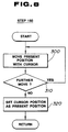
- Fig. 8 is a detailed flowchart for explaining details of a manual correction subroutine (step 180) shown in Fig. 3.
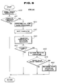
- Fig. 9 is a detailed flowchart for explaining details of a procedure of a map matching subroutine (step 240) in Fig. 4.
- Fig. 10 is an explanatory view for explaining a procedure in a case where points of candidates detected on a road are sorted in an order in which a point on a road which is nearest to the present position is first.
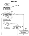
- Fig. 11 is a detailed flowchart for explaining details of a spiral search subroutine (step 400) shown in Fig. 9.
- Fig. 12 is an explanatory view for explaining an arrangement order of pixels in a set state of a block on a displayed image for the spiral search in Fig. 11.
- Fig. 13 is an explanatory view for explaining a next block position search in Fig. 11.
- Fig. 14 is an explanatory view for explaining the spiral search for the next block position in Fig. 11.
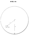
- Fig. 15 is an explanatory view for explaining an area of a searched block in Fig. 11.
- Fig. 16 is a flowchart for explaining a procedure of selecting a point of candidate through a sequential relaxation executed in a step 440 in Fig. 9.
- Fig. 17 is an explanatory view for explaining the memory locations of the D-RAM in which promising points of candidates are sequentially registered.
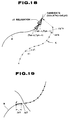
- Figs. 18 and 19 are explanatory views for explaining an action as executed in step 610 of Fig. 16 for searching points on the road by sequentially relaxing a locus form.
- Fig. 20 is a detailed flowchart for explaining another procedure for selecting points of candidate through sequential relaxation.
- Fig. 21 is an explanatory view of the locus data in a case when the locus data do not partially correspond to those on the road in Fig. 20.
- Fig. 22 is a detailed flowchart for explaining the details of a pattern match subroutine (step 460) shown in Fig. 9.
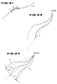
- Fig. 23 is an explanatory view for explaining an action of the pattern matching.
- Fig. 24 is an explanatory view for explaining the action of the pattern matching.
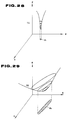
- Fig. 25 is an explanatory view for explaining an action of detecting the residual square sum of distances between locus data and each point on the road which corresponds to a locus data.
- Fig. 26 is an explanatory view for explaining an action of calculating a minimum value Emin of the residual square sum.
- Fig. 27 is a flowchart for explaining details of a match point particular subroutine in Fig. 9.
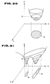
- Figs 28 to 31 are explanatory views for explaining actions in the case where the present position is corrected on the basis of the standard deviation and the correlation coefficient .
- Fig. 1 shows a hardware construction of a route guide system for a vehicle to which a system for displaying the present position of a moving object according to the present invention is applicable.
- the route guide system shown in Fig. 1 includes a microcomputer having a CPU 1 which governs the whole system operation.
- a system bus 2 is connected to I/O controllers 3 and 4, an SCSI controller 5, graphic controller 6, V (Video)-RAM 7, ROM 8, D (Drive)-RAM 9, Kanji (Chinese Character) ROM 10, and back-up RAM 11.
- a directional sensor 12 is connected to the I/O controller 3 via an amplifier AMP 14 and A/D converter 15, and a distance sensor 13 is connected to the I/O controller 3.
- the structure of the directional sensor 12 is exemplified by U.S. Patent No. 4, 442,609 issued on April 17, 1984, and the structure of the distance sensor 13 is exemplified by U.S.Patent No. 4, 699,507 issued on October 13).
- a CD-ROM 19 and a CRT 20 are connected, respectively, to the SCSI controller 5 and graphic controller 6.
- the CRT 20 which functions as a VDT (Visual Display Terminal) mainly carries out a route guide of the vehicle to a destination for a vehicle occupant including a driver, and an image information to be displayed on the CRT 20 is temporarily written into the V-RAM 7 and the map information to be displayed on the CRT 20 is previously written into the CD-ROM 19.
- VDT Visual Display Terminal
- Signal outputs of a GPS (Geographic Positioning Satellite) Rx 22 and a beacon Rx 23 can be utilized via an expanded I/O controller 21 together with those derived from the direction sensor 12 and distance sensor 13 for the confirmation and detection of the present absolute position of the vehicle.
- GPS Geographic Positioning Satellite
- the CPU 1 executes a system program (Operating System, OS) stored in a ROM 8 to perform an overall control of the system.
- OS Operating System
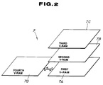
- Fig. 2 shows an explanatory view of the contents of the V-RAM 7 shown in Fig. 1.
- the V-RAM 7 includes a first V-RAM 7A for depicting a form of a road R, a second V-RAM 7B for depicting place names, etc., a third V-RAM 7C for displaying the present position or locus K of the running vehicle, and a fourth V-RAM 7D for depicting enlarged and scale-down maps.
- the V-RAM 7A for depicting the form of the road is constituted so as to provide a working area for drawing road data, as will be described later, and for performing a pattern matching of the road map data and locus data, as will be described later.
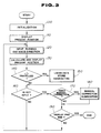
- Fig. 3 shows a general flowchart of a control program stored in the ROM 8 shown in Fig. 1 on which the system is controlled.
- a step 100 an initialization is carried out upon start of the main program.
- a step 110 an initial position of the vehicle is inputted and the present position of the vehicle and peripheral road map around the present position of the vehicle are simultaneously displayed by the CRT 20.
- the system Upon completion of the initialization and display processing of the present position, the system is in operation and in steps 120, 130, the present position detected by the direction sensor 12 and distance sensor 13 causes a sequential rewrite and a synthetic display of the displayed map on the screen of the CRT 20.
- the CPU 1 determines in a step 140 whether the vehicle has advanced over a unit distance denoted by ⁇ l1.
- step 140 the routine goes to a subroutine (step 150) for storing a locus data, as will be described later.
- a calculation processing such as to derive the present position of the vehicle utilizes the locus data which is essential to the present invention.
- the routine goes to a step 160 in which the CPU 1 determines whether a key input is present. If no key input is present (No in the step 160), the series of processings of the steps 120 through 150 is repeated. If Yes in the step 160 (the key input is present), the CPU 1 determines whether a manual correction is approved in a step 170.
- step 180 determines whether the present position display processing is ended in a step 190. If yes in the step 190, the display processing is ended.
- the subroutine shown in Fig. 8 is executed when an automatic correction for displaying the present position, as will be described later, becomes impossible.
- this routine is executed in a case where the vehicle runs for a long distance on a road whose map is not stored into the CD-ROM 19 or in a case where the vehicle is transported on a marine route when using a ferry boat.
- steps 300 through 320 the setting of the vehicle present position is carried out by displaying a map on the screen of the CRT 20 and moving a cursor (not shown) through an operation of the key 16.
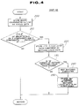
- Fig. 4 shows the subroutine (step 150) for storing the locus data.
- the essential portion of the system in the preferred embodiment will be described in accordance with the subroutine shown in Fig. 4.
- movement components ( ⁇ x i , ⁇ y i ) in x- and y-axis directions for each unit distance ⁇ l1 are stored as the locus data in a step 200.
- the locus data is stored into a circular buffer 30 installed in the D-RAM 9 as shown in Fig. 5.
- the circular buffer 30 is constructed so as to store a required number of locus data in such an order as ( ⁇ x1, ⁇ y1), ( ⁇ x2, ⁇ y2), --- ( ⁇ x M , ⁇ y M ) by a past M number of the locus data.
- the CPU 1 determines whether a minor total of movement components in the x-axis (horizontal) direction or y-axis (vertical) direction from among the locus data stored in the step 200 exceeds a predetermined valve ⁇ l2.
- the CPU 1 determines whether one of the minor totals of the movement components in the x-axis direction and y-axis direction from among the locus data stored in the step 200 exceeds ⁇ l2.
- step 210 i.e., whenever one of the minor sums of the movement components in the x-axis and y-axis directions has exceeded ⁇ l2, in order to further coarsely providing a discrete processing for the movement components stored in the step 200 for later processing conveniences, the routine goes to a step 220.
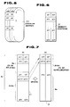
- Fig. 6 shows a memory configuration of memory locations 31 within the D-RAM 9 in which the above-described pattern matching locus data ( ⁇ x', ⁇ y') are stored.
- the CPU 1 determines whether N number of the locus data for pattern matching are stored (N ⁇ M).
- step 250 the routine goes to a step 250 in which No number of locus data from the N number of the collected pattern matching locus data ( ⁇ x', ⁇ y') are deleted in the older order (provided that No ⁇ N).
- Fig. 7 shows a processing method executed in the step 250.
- (N - No) number of the data are left therein.
- the map matching processing is executed in the step 240 whenever the No number of the pattern matching locus data ( ⁇ x', ⁇ y') are newly supplemented into the corresponding memory locations 31.
- Fig. 9 shows a detailed flowchart of the above-described map matching subroutine (step 240).
- a point of candidate which is determined as the present position of the vehicle on any one of roads surrounding the present position is spirally searched (refer to Fig. 10).
- the routine goes to a step 420 in which an approximate point vanish processing, as will be described below, is executed.
- any two points of candidate whose mutual interval distance is too approximate (too short) is deleted.
- the step of 420 can, thus, reduce a number of times complicated calculations are carried out at the subsequent steps of calculating the present position on the basis of the points of candidate for the present position of the vehicle.
- the points of candidates derived in the preceding processing are rearranged in an order of the candidate points which are nearer to the present position (, i.e., the nearest point of candidate is first).
- the points of candidates are searched spirally in an arrow-marked direction denoted by S with the present position of the vehicle P as the center, the points of candidates are derived in such an order as 1 ⁇ 2 ⁇ 3 ⁇ 4 ⁇ 5 in accordance with the order of searching on the road R.
- a point of candidate nearest to the present position is 3.
- the searched point 3 of the candidate is later in the order than 1 and 2, as appreciated from Fig. 10.
- the processing of step 430 causes an order rearrangement of the points of candidate in such an order that each point of candidate nearer to the present position P becomes earlier.
- a step 440 an overlapping of the running locus and road for each point of candidate derived heretofore is carried out, a selection of the point of candidate is carried out in such a way that a point at which the overlapping can be made through a "relaxation" (explained below) within a range defined by a certain allowance limit is determined as a promising point of candidate.
- a step 450 the CPU 1 determines whether the promising point of candidate is left as the result of such a selection. If Yes in the step 450 (the promising point of candidate is left), the routine advances to a pattern matching subroutine in a step 460.
- the CPU 1 carries out the rotation of the running locus trajectory or form, with the promising point of candidate as a center, as will be described later, and derives an error value in relation with corresponding points on the road with respect to the promising point of candidate.
- a step 470 the CPU 1 determines whether at least one promising point of candidate such that the error value is below a threshold value is present.
- the routine goes to a step 480 in which a matched point specifying subroutine is executed.
- step 480 the present position of the vehicle is corrected to the most suitable position from among the plurality of promising points of candidate on the basis of the result of calculations of a standard deviation and correlation coefficient associated to each promising point of candidate, as will be described later.
- Fig. 11 shows a detailed spiral search subroutine in the step 400.
- a width of an area to be searched is calculated in a step 500.
- the width of the area is denoted by a circle having a radius of R with the present position as a center, as shown in Fig. 15.
- an output error of the direction sensor 12 drawing error of the map, and accuracy value when the position was previously corrected are used as base values.
- the value of R may be rough.
- R R ⁇ 1 + a x (b - E) + c x L
- R ⁇ 1 denotes the value of R at the previous time of correction
- E denotes the probability density associated to previously corrected position
- L denotes the running distance from a previously corrected position
- a, b, and c denote constants.
- the probability density E can be derived from the following equation.
- y denotes a value of the y coordinate of the previously position corrected point
- x denotes the average value of the x-axis coordinates of the previous promising points of candidate
- y denotes the average value of the y-axis coordinates of the previous promising points of candidate
- ⁇ x denotes the deviation of the x coordinates of the previous promising candidate points
- ⁇ y denotes the deviation of the y coordinates of the previous promising points of candidate.
- the positional error is independent in the x axis and y axis directions and accords with a normal distribution.
- the CPU 1 searches in a step 510 whether a point on the road is present in the circle having the radius of R.
- Such a searching as described above in the step 510 is carried out to check whether a point on the road is present within the square-formed block 32 having each side of three parallel pixels drawn on the V-RAM 7A (for drawing the form of road), as shown in Fig. 12.
- the CPU 1 determines whether the block 32 constituted by pixels of 1 through 9 is set spirally in the clockwise direction, the pixel placed on the center being 1. If the pixels 1 through 9 which are spirally set as described above are present, the CPU 1 determines that the point on the road is present within the corresponding block (Yes in the step 510) and determines the point of the road within the block thus found present as one point of candidate in a step 550.
- the calculation of the subsequent block position is executed in such a way as in a spiral form as denoted by the arrow-marked direction S with the present position P as a center so as not to overlap with the block which was previously searched, as shown in Fig. 13.
- Fig. 14 is an explanatory view of the result of calculation of the subsequent block position.
- the CPU 1 calculates the subsequent block positions to be spirally searched in the arrow-marked direction S in such an order as 1, 2, 3,---, 10, --, as shown in Fig. 14.
- a step 530 the CPU 1 determines whether the next block position thus calculated falls in a radius of R with the present position P as a center.
- the CPU 1 determines that r ⁇ R and it falls in the area (Yes) and the routine goes to a step 540 in which the set state of each pixel in the block 32 is determined.
- the CPU 1 determines that a point is present on the road within the block and the point on the block is detected as the point of candidate in a step 550.
- the new subsequent block search is executed in the order shown in Fig. 14.
- Such a processing as described above is executed for all blocks which fall in the radius R of the circle with the present position P as a center.
- Fig. 16 is a detailed flowchart of the above-described step 440 shown in Fig. 9.
- any one point on the road detected in the processing of step 550 is selected in a step 600.
- a step 610 the CPU 1 carries out such processings that the locus form is sequentially relaxed on the basis of the selected point of candidate, searching corresponding points on the road.
- the CPU 1 subtracts the N order data ( ⁇ x N' , ⁇ y N' ) which is the last data of the locus data stored in the memory locations 31 from the selected point of candidate (xd, yd).
- Kx n-1 xd - ⁇ x N'
- Ky n-1 yd - ⁇ y N' .
- the CPU 1 searches whether the point on the road is present within a range of ⁇ ⁇ °, with the point of candidate (Kxn, Kyn) shown in Fig.
- this point is set as the corresponding point (Tx n-1 , Ty n-1 ) on the road, corresponding to (Kx n-1 , Ky n-1 ).
- a step 620 the CPU 1 determines whether N number of locus data ( ⁇ xl', ⁇ yl') --- ( ⁇ x N ', ⁇ y N ') correspond to points on the road R.
- the actually investigated point of candidate (xdi, ydi) is registered in a step 630 into the memory location 34 within the D-RAM 9 as the promising point of candidate for the present position of the vehicle as shown in Fig. 17.
- the feature of procedure shown in Fig. 20 is that even if the CPU 1 determines that not all N locus data correspond to points on the road (No in a step 620'), the CPU 1 determines in a step 650' whether the number of the points of the locus trajectory which do not have corresponding points of the road fall in the range of a constant ⁇ N. If the number is within the constant ⁇ N (Yes in a step 650'), such points of candidate are also registered as promising points of candidate in a step 630'
- Fig. 21 shows an example of the result of such a procedure as described above in the case of Fig. 20.
- the locus data a and b are not placed on the road R.
- the pattern matching processing is carried out in the step 460 utilizing the promising points of candidate.
- Fig. 22 shows the detailed flowchart of processing the step 460.
- the CPU 1 picks up one of the promising points of candidate derived in the step 440.
- steps 710 and 720 supposing that the present position of the vehicle is placed on the picked up promising point of candidate, the CPU 1 carries out a parallel translation of a whole locus form K with the present position substituted for the promising point of candidate (xdi, ydi) shown in Fig. 23.
- a step 730 the CPU 1 carries out a rotation of the whole locus form K within a range of ⁇ ⁇ 2° for each unit angle with the promising point of candidate (xdi, ydi) as a center, as shown in Fig. 24.
- a step 740 the CPU 1 derives a minimum value E min of a square sum E of a distance between each point on the locus form K and the corresponding point on the road form R, both points constituting one of set of point on the road and locus forms.
- Kx ⁇ (i) denotes the x coordinate in the order i when the whole locus form is rotated through ⁇ °
- Ky ⁇ (i) denotes the y coordinate in the order i when the whole locus form is rotated through ⁇ °
- Tx(i) denotes the x coordinate of the point on the road corresponding to Kx ⁇ (i)
- Ty(i) denotes the y coordinate of the point on the road corresponding to Ky ⁇ (i).
- Fig. 25 shows the distances between the locus form points and the corresponding points on the road, denoted by L1, L2,---, Li, ---, L N .
- Fig. 26 shows a graph for explaining the calculation of the minimum value E min .
- the minimum value E min is derived at the rotational angle of ⁇ min .
- the CPU 1 determines the derived E min as an error value at the promising point of candidate (xdi, ydi).
- the routine returns to the step 470 in which the CPU 1 determines whether at least one of the promising points of candidate whose error value is below a threshold value Tl is present. If such a maintained point as described above is present in the step 470, a processing of a matched point specification in the step 480 is carried out.
- Fig. 27 shows a detailed flowchart of the processing in the step 480.
- the routine starts a step 800 in which the standard deviation for the coordinate rows of the maintained promising points of candidates is calculated by the following equation.
- Np denotes the number of coordinate rows of the maintained promising points of candidate
- xi denotes the x coordinate of the maintained promising point of candidate in the i order
- yi denotes the y coordinate of the maintained promising point of candidate in the i order
- x denotes the average value of the x coordinates of the maintained promising points of candidate
- y denotes the average value of the y coordinates of the maintained promising points of candidate.
- x and y are mutually independent.
- the CPU 1 derives the correlation coefficient ⁇ for the maintained promising points of candidate using the following equation. As described above, when the standard deviation ⁇ and correlation coefficient ⁇ are derived for the coordinate rows of the maintained promising points of candidate, a maintained promising point of candidate which is most suitable for the positional correction is derived from among the maintained promising points of candidate.
- the locus data for each unit distance run is stored and points of candidate for the present position are spirally searched on any road peripheral to the present position, a locus form based on each unit distance run on the basis of the locus data stored as described above with the searched point of candidate being as a start point, is specified from the stored locus data, and road map pattern matching is provided, the present position can accurately be detected without failure even when the moving object has run for a long duration of time.
Description
- The present invention relates to a system for displaying the present position of a moving object, applicable to a navigation system for a vehicle.
- A Japanese Patent Application First Publication (non-examined) Showa 58-223016 published on December 24, 1983 exemplifies a previously proposed system for displaying the present position of a moving object such as a vehicle on a road map image.
- In the previously proposed system, a running distance of the vehicle is detected by a running distance detector, a travel direction is detected by a direction detector, a displayed map is sequentially updated as the present position is moved such that a displayed point indicating the present position of the vehicle is passed through the displayed map, and the displayed point is synthesized (superposed) so as to be displayed on the updated map.
- In more details, the present position (Xt, Yt) of the moving object at a certain time t in a plane of X-Y coordinates is derived from the following equation.


In the above two equations, (Xt-1, Yt-1) denotes a previous position of the vehicle before ΔT second, Δℓ denotes the running distance within a time Δt, and ϑt denotes the running direction within the time Δt. - However, since the previously proposed system calculates the present position by accumulating the running distances per unit time in the X-axis direction and in the Y-axis direction, respectively, detection errors of the running distance detector and also of the direction detector are accumulated. Thus, as the vehicle runs for a long period of time, large positional errors for the present position will eventually occur.
- A system having the features a) to g) of appended
claim 1 is known from the document EP-A-0 270 911. Further, this prior art system comprises means which are similar to the means h), i), and m) of the appendedclaim 1. This system computes correlation coefficients concerning the correlation between a road form pattern and a running locus form pattern. The correlation coefficient whose error is smallest with respect to an estimated location is selected, and the registered estimated location corresponding to said selected correlation coefficient is outputted as the present location. - A similar system is known from the document EP-
A-0 110 171. This document however merely describes that pattern recognition is provided between prestored road form patterns and a running locus form pattern; no details are given concerning the pattern recognition. - It is the object of the present invention to provide a system for very accurately detecting and displaying the position of a moving object.
- This object is solved by a system according to the teaching of appended
claim 1. - Fig. 1 is a schematic circuit block diagram of a system for displaying the present position of a moving object in a preferred embodiment according to the present invention.
- Fig. 2 is a schematic drawing of a V-RAM shown in Fig. 1.
- Fig. 3 is a general flowchart for explaining a series of processes executed in the preferred embodiment shown in Fig. 1.
- Fig. 4 is a detailed flowchart of a locus data store subroutine (step 150) in Fig. 3.
- Fig. 5 is an explanatory view of a circular buffer in which a locus data for each running distance per unit time is sequentially stored.
- Fig. 6 is an explanatory view of memory locations of a D-RAM shown in Fig. 1 in which the locus data for each predetermined distance run is sequentially stored.
- Fig. 7 is an explanatory view of a supplemental (update) action of the locus data stored in the memory locations.
- Fig. 8 is a detailed flowchart for explaining details of a manual correction subroutine (step 180) shown in Fig. 3.
- Fig. 9 is a detailed flowchart for explaining details of a procedure of a map matching subroutine (step 240) in Fig. 4.
- Fig. 10 is an explanatory view for explaining a procedure in a case where points of candidates detected on a road are sorted in an order in which a point on a road which is nearest to the present position is first.
- Fig. 11 is a detailed flowchart for explaining details of a spiral search subroutine (step 400) shown in Fig. 9.
- Fig. 12 is an explanatory view for explaining an arrangement order of pixels in a set state of a block on a displayed image for the spiral search in Fig. 11.
- Fig. 13 is an explanatory view for explaining a next block position search in Fig. 11.
- Fig. 14 is an explanatory view for explaining the spiral search for the next block position in Fig. 11.
- Fig. 15 is an explanatory view for explaining an area of a searched block in Fig. 11.
- Fig. 16 is a flowchart for explaining a procedure of selecting a point of candidate through a sequential relaxation executed in a
step 440 in Fig. 9. - Fig. 17 is an explanatory view for explaining the memory locations of the D-RAM in which promising points of candidates are sequentially registered.
- Figs. 18 and 19 are explanatory views for explaining an action as executed in
step 610 of Fig. 16 for searching points on the road by sequentially relaxing a locus form. - Fig. 20 is a detailed flowchart for explaining another procedure for selecting points of candidate through sequential relaxation.
- Fig. 21 is an explanatory view of the locus data in a case when the locus data do not partially correspond to those on the road in Fig. 20.
- Fig. 22 is a detailed flowchart for explaining the details of a pattern match subroutine (step 460) shown in Fig. 9.
- Fig. 23 is an explanatory view for explaining an action of the pattern matching.
- Fig. 24 is an explanatory view for explaining the action of the pattern matching.
- Fig. 25 is an explanatory view for explaining an action of detecting the residual square sum of distances between locus data and each point on the road which corresponds to a locus data.
- Fig. 26 is an explanatory view for explaining an action of calculating a minimum value Emin of the residual square sum.
- Fig. 27 is a flowchart for explaining details of a match point particular subroutine in Fig. 9.
- Figs 28 to 31 are explanatory views for explaining actions in the case where the present position is corrected on the basis of the standard deviation and the correlation coefficient .
- Reference will hereinafter be made to the drawings in order to facilitate a better understanding of the present invention.
- Fig. 1 shows a hardware construction of a route guide system for a vehicle to which a system for displaying the present position of a moving object according to the present invention is applicable.
- The route guide system shown in Fig. 1 includes a microcomputer having a
CPU 1 which governs the whole system operation. - A
system bus 2 is connected to I/O controllers SCSI controller 5,graphic controller 6, V (Video)-RAM 7,ROM 8, D (Drive)-RAM 9, Kanji (Chinese Character)ROM 10, and back-up RAM 11. - A
directional sensor 12 is connected to the I/O controller 3 via anamplifier AMP 14 and A/D converter 15, and adistance sensor 13 is connected to the I/O controller 3. (The structure of thedirectional sensor 12 is exemplified by U.S. Patent No. 4, 442,609 issued on April 17, 1984, and the structure of thedistance sensor 13 is exemplified by U.S.Patent No. 4, 699,507 issued on October 13). - A
key 16 provided on a key board for operating various inputs for the system, e.g., an initially set position of the vehicle, is connected to the I/O controller 4 and aspeaker 17 is connected to asound generator 18. - On the other hand, a CD-
ROM 19 and aCRT 20 are connected, respectively, to theSCSI controller 5 andgraphic controller 6. - The CRT 20 which functions as a VDT (Visual Display Terminal) mainly carries out a route guide of the vehicle to a destination for a vehicle occupant including a driver, and an image information to be displayed on the
CRT 20 is temporarily written into the V-RAM 7 and the map information to be displayed on theCRT 20 is previously written into the CD-ROM 19. - Signal outputs of a GPS (Geographic Positioning Satellite)
Rx 22 and abeacon Rx 23 can be utilized via an expanded I/O controller 21 together with those derived from thedirection sensor 12 anddistance sensor 13 for the confirmation and detection of the present absolute position of the vehicle. - The
CPU 1 executes a system program (Operating System, OS) stored in aROM 8 to perform an overall control of the system. - Fig. 2 shows an explanatory view of the contents of the V-
RAM 7 shown in Fig. 1. - In Fig. 2, the V-
RAM 7 includes a first V-RAM 7A for depicting a form of a road R, a second V-RAM 7B for depicting place names, etc., a third V-RAM 7C for displaying the present position or locus K of the running vehicle, and a fourth V-RAM 7D for depicting enlarged and scale-down maps. The V-RAM 7A for depicting the form of the road is constituted so as to provide a working area for drawing road data, as will be described later, and for performing a pattern matching of the road map data and locus data, as will be described later. - It is noted that in a case where various kinds of information are displayed on the
CRT 20, some pages of each V-RAM 7A through 7D are arbitrarily retrieved, superposed, and displayed through theCRT 20. - Fig. 3 shows a general flowchart of a control program stored in the
ROM 8 shown in Fig. 1 on which the system is controlled. - The whole construction of the control program will hereinbelow be described with reference to Fig. 3.
- In a step 100, an initialization is carried out upon start of the main program.
- In a
step 110, an initial position of the vehicle is inputted and the present position of the vehicle and peripheral road map around the present position of the vehicle are simultaneously displayed by theCRT 20. - Upon completion of the initialization and display processing of the present position, the system is in operation and in
steps direction sensor 12 anddistance sensor 13 causes a sequential rewrite and a synthetic display of the displayed map on the screen of theCRT 20. - When such synthetic (superimpose) display processings on the present position and its peripheral road map are repeated, the
CPU 1 determines in astep 140 whether the vehicle has advanced over a unit distance denoted by Δℓ₁. - If yes in the step 140 (the vehicle has advanced over Δℓ₁), the routine goes to a subroutine (step 150) for storing a locus data, as will be described later. Thus, a calculation processing such as to derive the present position of the vehicle utilizes the locus data which is essential to the present invention.
- On the other hand, in a case where the vehicle has not advanced over Δℓ₁ (No in the step 140), the routine goes to a
step 160 in which theCPU 1 determines whether a key input is present. If no key input is present (No in the step 160), the series of processings of thesteps 120 through 150 is repeated. If Yes in the step 160 (the key input is present), theCPU 1 determines whether a manual correction is approved in astep 170. - If Yes in the step 170 (manual correction is needed), the routine advances to a manual correction subroutine (step 180). If no manual correction is needed in the step 170 (No), the
CPU 1 determines whether the present position display processing is ended in astep 190. If yes in thestep 190, the display processing is ended. - Next, the subroutine of manual correction processing will be described with reference to Fig. 8.
- The subroutine shown in Fig. 8 is executed when an automatic correction for displaying the present position, as will be described later, becomes impossible. For example, this routine is executed in a case where the vehicle runs for a long distance on a road whose map is not stored into the CD-
ROM 19 or in a case where the vehicle is transported on a marine route when using a ferry boat. - In
steps 300 through 320, the setting of the vehicle present position is carried out by displaying a map on the screen of theCRT 20 and moving a cursor (not shown) through an operation of the key 16. - Fig. 4 shows the subroutine (step 150) for storing the locus data. The essential portion of the system in the preferred embodiment will be described in accordance with the subroutine shown in Fig. 4.
- Upon start of the program, movement components (Δxi, Δyi) in x- and y-axis directions for each unit distance Δℓ₁ are stored as the locus data in a
step 200. - The locus data is stored into a
circular buffer 30 installed in the D-RAM 9 as shown in Fig. 5. - The
circular buffer 30 is constructed so as to store a required number of locus data in such an order as (Δx₁, Δy₁), (Δx₂, Δy₂), --- (ΔxM, ΔyM) by a past M number of the locus data. - In the
next step 210, theCPU 1 determines whether a minor total of movement components in the x-axis (horizontal) direction or y-axis (vertical) direction from among the locus data stored in thestep 200 exceeds a predetermined valve Δℓ₂. - This is because the movement components stored in the
step 200 are subjected to more precise discrete processing. In astep 210, theCPU 1 determines whether one of the minor totals of the movement components in the x-axis direction and y-axis direction from among the locus data stored in thestep 200 exceeds Δℓ₂. - If Yes in the
step 210, i.e., whenever one of the minor sums of the movement components in the x-axis and y-axis directions has exceeded Δℓ₂, in order to further coarsely providing a discrete processing for the movement components stored in thestep 200 for later processing conveniences, the routine goes to astep 220. - For example, supporting that


and the minor total in the x-axis direction, i.e., Δxt is expressed as Δxt ≧ Δℓ₂, the present data (Δxt, Δyt) are stored instep 200 as the locus data (Δxi', Δyi') to be subjected to a pattern matching. - Fig. 6 shows a memory configuration of
memory locations 31 within the D-RAM 9 in which the above-described pattern matching locus data (Δx', Δy') are stored. - Then, in a
step 230, theCPU 1 determines whether N number of the locus data for pattern matching are stored (N < M). - If Yes, i.e., the N number of the locus data are collected as shown in Fig. 6, the routine goes to a
step 240 in which a map matching subroutine is executed as will be described later. - Upon completion of the processing of
step 240, the routine goes to astep 250 in which No number of locus data from the N number of the collected pattern matching locus data (Δx', Δy') are deleted in the older order (provided that No < N). - Fig. 7 shows a processing method executed in the
step 250. In thememory locations 31, (N - No) number of the data are left therein. - Then, as shown in (b) of Fig. 7, the map matching processing is executed in the
step 240 whenever the No number of the pattern matching locus data (Δx', Δy') are newly supplemented into thecorresponding memory locations 31. - Fig. 9 shows a detailed flowchart of the above-described map matching subroutine (step 240).
- In a
step 400, a point of candidate which is determined as the present position of the vehicle on any one of roads surrounding the present position is spirally searched (refer to Fig. 10). - If the point of candidate to automatically correct the present position is present on any one of the peripheral roads as the result of the above-described spiral search in the
step 410, the routine goes to astep 420 in which an approximate point vanish processing, as will be described below, is executed. - That is to say, in the processing of the
step 420, any two points of candidate whose mutual interval distance is too approximate (too short) is deleted. - For example, if in any two points of candidate, the mutual distances are shorter than ℓ₃ which corresponds to three adjacent pixels on the V-
RAM 7A, one of the two points of candidate is deleted (vanished). - The step of 420 can, thus, reduce a number of times complicated calculations are carried out at the subsequent steps of calculating the present position on the basis of the points of candidate for the present position of the vehicle.
- In a sorting processing of the candidate points of a
step 430, the points of candidates derived in the preceding processing (steps - As shown in Fig. 10, in a case where the points of candidates are searched spirally in an arrow-marked direction denoted by S with the present position of the vehicle P as the center, the points of candidates are derived in such an order as ① → ② → ③ → ④ → ⑤ in accordance with the order of searching on the road R.
- In Fig. 10, a point of candidate nearest to the present position is ③. However, the searched
point ③ of the candidate is later in the order than ① and ②, as appreciated from Fig. 10. Then, the processing ofstep 430 causes an order rearrangement of the points of candidate in such an order that each point of candidate nearer to the present position P becomes earlier. - Hence, in the example of Fig. 10, the order is rearranged as ③ → ② → ① → ④ → ⑤.
- In a
step 440, an overlapping of the running locus and road for each point of candidate derived heretofore is carried out, a selection of the point of candidate is carried out in such a way that a point at which the overlapping can be made through a "relaxation" (explained below) within a range defined by a certain allowance limit is determined as a promising point of candidate. - In a
step 450, theCPU 1 determines whether the promising point of candidate is left as the result of such a selection. If Yes in the step 450 (the promising point of candidate is left), the routine advances to a pattern matching subroutine in astep 460. - In the
step 460, theCPU 1 carries out the rotation of the running locus trajectory or form, with the promising point of candidate as a center, as will be described later, and derives an error value in relation with corresponding points on the road with respect to the promising point of candidate. - In a
step 470, theCPU 1 determines whether at least one promising point of candidate such that the error value is below a threshold value is present. - If there is a promising point of candidate whose associated error value is below the threshold value in the step of 470, the routine goes to a
step 480 in which a matched point specifying subroutine is executed. - In
step 480, the present position of the vehicle is corrected to the most suitable position from among the plurality of promising points of candidate on the basis of the result of calculations of a standard deviation and correlation coefficient associated to each promising point of candidate, as will be described later. - Hereinafter, the procedure of
steps 400 through 480 will be described in detail. - Fig. 11 shows a detailed spiral search subroutine in the
step 400. - In the processing shown in Fig. 11, a width of an area to be searched is calculated in a
step 500. - The width of the area is denoted by a circle having a radius of R with the present position as a center, as shown in Fig. 15. To calculate the radius of R, an output error of the
direction sensor 12, drawing error of the map, and accuracy value when the position was previously corrected are used as base values. The value of R may be rough. - For example, hence, the value of R can be derived in accordance with the following equation:

In the equation described above, R₋₁ denotes the value of R at the previous time of correction, E denotes the probability density associated to previously corrected position, L denotes the running distance from a previously corrected position, and a, b, and c denote constants. - It is noted that the probability density E can be derived from the following equation.

In the equation described above,denotes a value of x coordinate of the previously position corrected point, y denotes a value of the y coordinate of the previously position corrected point,
x denotes the average value of the x-axis coordinates of the previous promising points of candidate,y denotes the average value of the y-axis coordinates of the previous promising points of candidate, σx denotes the deviation of the x coordinates of the previous promising candidate points, σy denotes the deviation of the y coordinates of the previous promising points of candidate. - It is noted that the positional error is independent in the x axis and y axis directions and accords with a normal distribution.
- When the radius R of the area to be searched is derived through the processing of the
step 500, theCPU 1 searches in astep 510 whether a point on the road is present in the circle having the radius of R. - Such a searching as described above in the
step 510 is carried out to check whether a point on the road is present within the square-formedblock 32 having each side of three parallel pixels drawn on the V-RAM 7A (for drawing the form of road), as shown in Fig. 12. - That is to say, the
CPU 1 determines whether theblock 32 constituted by pixels of 1 through 9 is set spirally in the clockwise direction, the pixel placed on the center being 1. If thepixels 1 through 9 which are spirally set as described above are present, theCPU 1 determines that the point on the road is present within the corresponding block (Yes in the step 510) and determines the point of the road within the block thus found present as one point of candidate in astep 550. - On the other hand, if the pixels within the searched block are not set in a state shown in Fig. 12, the calculation of the block position next to be searched is executed in a
step 520. - The calculation of the subsequent block position is executed in such a way as in a spiral form as denoted by the arrow-marked direction S with the present position P as a center so as not to overlap with the block which was previously searched, as shown in Fig. 13.
- Fig. 14 is an explanatory view of the result of calculation of the subsequent block position.
- After the pixels set state of the
first block 32a are searched at the first place, theCPU 1 calculates the subsequent block positions to be spirally searched in the arrow-marked direction S in such an order as 1, 2, 3,---, 10, --, as shown in Fig. 14. - In a
step 530, theCPU 1 determines whether the next block position thus calculated falls in a radius of R with the present position P as a center. - As shown in Fig. 15, the
CPU 1 determines that r < R and it falls in the area (Yes) and the routine goes to astep 540 in which the set state of each pixel in theblock 32 is determined. - If the pixels are spirally set in the step 540 (Yes), the
CPU 1 determines that a point is present on the road within the block and the point on the block is detected as the point of candidate in astep 550. - On the other hand, if the pixels within the block to be searched are not in the spirally set state and the corresponding point on the road is not detected (No in the step 540), the new subsequent block search is executed in the order shown in Fig. 14.
- Such a processing as described above (
steps 520 through 550) is executed for all blocks which fall in the radius R of the circle with the present position P as a center. - In this way, when the point of the road is derived as the point of candidate in the circle of radius R with the present position P as the center, the processings of the
steps 410 through 430 are carried out. Then, such a processing as the selection of the point of candidate through a sequential relaxation is carried out. - Fig. 16 is a detailed flowchart of the above-described
step 440 shown in Fig. 9. - In the above-described processing, any one point on the road detected in the processing of
step 550 is selected in astep 600. - In a
step 610, theCPU 1 carries out such processings that the locus form is sequentially relaxed on the basis of the selected point of candidate, searching corresponding points on the road. - As shown in Fig. 18, suppose that the selected point of candidate is (xd, yd). The
CPU 1 subtracts the N order data (ΔxN', ΔyN') which is the last data of the locus data stored in thememory locations 31 from the selected point of candidate (xd, yd). - This derives the coordinates (Kxn-1, Kyn-1) before one unit distance from the present position when the locus K itself is parallel transformed onto the road.
- That is to say,


(Provided that Kxn = xd and Xyn = yd)
To pick up a point on the road corresponding to (Kxn-1, Kyn-1), theCPU 1 searches whether the point on the road is present within a range of ± ϑ°, with the point of candidate (Kxn, Kyn) shown in Fig. 18 as a center, with the running direction at the point of candidate (Kxn, Kyn) as a reference, and on a circumference of a circle having a radius expressed as follows : √(ΔxN')² + (ΔyN')². - Then, if such a point as defined as above is present, this point is set as the corresponding point (Txn-1, Tyn-1) on the road, corresponding to (Kxn-1, Kyn-1).
- On the other hand, if the above-described point is not present, the
CPU 1 determines it as the not corresponding point and sets (Txn-1, Tyn-1) in the following:


Furthermore,


In the same technique, theCPU 1 derives (Txn-2, Tyn-2) by relaxing (Kxn-2, Kyn-2) with (Kxn-1, Kyn-1) as a center. - Thereafter, the relaxation is repeated for each locus data (Δxi', Δyi') stored in the
memory location 31, as shown in Fig. 19. - In a
step 620, theCPU 1 determines whether N number of locus data (Δxl', Δyl') --- (ΔxN', ΔyN') correspond to points on the road R. - When all N locus data correspond to the points on the road (Yes in the step 620), the actually investigated point of candidate (xdi, ydi) is registered in a
step 630 into thememory location 34 within the D-RAM 9 as the promising point of candidate for the present position of the vehicle as shown in Fig. 17. - The above-described processing is carried out for all points of candidate in a
step 640. - Thus, the effective selection of the points of candidate and drawing out of the road form can simultaneously be executed.
- In the series of processings shown in Fig. 16, which shows the details of the
step 440, when all N locus data stored in thememory location 31 correspond to the points on the road, the points of candidate are registered as the promising points of candidate. However, if not all N locus data correspond to the points on the road, points of candidates are registered as the promising points of candidate as shown in a flowchart of Fig. 20. - The feature of procedure shown in Fig. 20 is that even if the
CPU 1 determines that not all N locus data correspond to points on the road (No in a step 620'), theCPU 1 determines in a step 650' whether the number of the points of the locus trajectory which do not have corresponding points of the road fall in the range of a constant ΔN. If the number is within the constant ΔN (Yes in a step 650'), such points of candidate are also registered as promising points of candidate in a step 630' - Fig. 21 shows an example of the result of such a procedure as described above in the case of Fig. 20. In Fig. 21, the locus data a and b are not placed on the road R.
- However, in the example shown in Fig. 20, in the case where the number locus data not placed on the road R is below the constant, the picked-up points of candidate are registered as the promising points of candidate.
- Therefore, even if the road form stored in the CD-
ROM 19 is more or less different from the actual form of the road, there is no problem. Then, even if a recirculation due to road construction and generation of local error of the sensor(s) occur, there is no problem. - After the processing in the
step 440 is carried out, the pattern matching processing is carried out in thestep 460 utilizing the promising points of candidate. - Fig. 22 shows the detailed flowchart of processing the
step 460. - In a
step 700 of Fig. 22, theCPU 1 picks up one of the promising points of candidate derived in thestep 440. - In
steps CPU 1 carries out a parallel translation of a whole locus form K with the present position substituted for the promising point of candidate (xdi, ydi) shown in Fig. 23. - In a
step 730, theCPU 1 carries out a rotation of the whole locus form K within a range of ± ϑ₂° for each unit angle with the promising point of candidate (xdi, ydi) as a center, as shown in Fig. 24. - In a
step 740, theCPU 1 derives a minimum value Emin of a square sum E of a distance between each point on the locus form K and the corresponding point on the road form R, both points constituting one of set of point on the road and locus forms.
In the above equation, Kxϑ(i) denotes the x coordinate in the order i when the whole locus form is rotated through ϑ°, Kyϑ(i) denotes the y coordinate in the order i when the whole locus form is rotated through ϑ°, Tx(i) denotes the x coordinate of the point on the road corresponding to Kxϑ(i), and Ty(i) denotes the y coordinate of the point on the road corresponding to Kyϑ(i). - Fig. 25 shows the distances between the locus form points and the corresponding points on the road, denoted by L₁, L₂,---, Li, ---, LN.
- Fig. 26 shows a graph for explaining the calculation of the minimum value Emin.
- As shown in Fig. 26, the minimum value Emin is derived at the rotational angle of ϑmin.
- In a
step 750, theCPU 1 determines the derived Emin as an error value at the promising point of candidate (xdi, ydi). - The series of processings at the
steps 700 through 750 are repeated until all points of promising candidate are dealt with, as judged in astep 760. - After the pattern matching processing is carried out in the
step 460, the routine returns to thestep 470 in which theCPU 1 determines whether at least one of the promising points of candidate whose error value is below a threshold value Tℓ is present. If such a maintained point as described above is present in thestep 470, a processing of a matched point specification in thestep 480 is carried out. - Fig. 27 shows a detailed flowchart of the processing in the
step 480. - Upon start of the program shown in Fig. 27, the routine starts a
step 800 in which the standard deviation for the coordinate rows of the maintained promising points of candidates is calculated by the following equation.
It is noted that Np denotes the number of coordinate rows of the maintained promising points of candidate, xi denotes the x coordinate of the maintained promising point of candidate in the i order, yi denotes the y coordinate of the maintained promising point of candidate in the i order,x denotes the average value of the x coordinates of the maintained promising points of candidate, andy denotes the average value of the y coordinates of the maintained promising points of candidate. - In addition, x and y are mutually independent.
- In a
step 810, theCPU 1 derives the correlation coefficient γ for the maintained promising points of candidate using the following equation.
As described above, when the standard deviation σ and correlation coefficient γ are derived for the coordinate rows of the maintained promising points of candidate, a maintained promising point of candidate which is most suitable for the positional correction is derived from among the maintained promising points of candidate. - The calculation methods for deriving the maintained promising point of candidate which is most suitable for the positional correction will be described below.
- (a)
If the standard deviation σ is less than a constant value σc due to small deviations of the maintained promising points of candidate (Yes in a step 820), the present position of the vehicle is corrected so so to make the error value Emin become minimum in astep 830.
This indicates that the point rows of the maintained promising points of candidate are squeezed in a pinhole configuration, as shown in oblique lines in Fig. 28. - (b)
On the other hand, if the standard deviation σ is above the constant value σc and the correlation coefficient γ is below a constant value γc (No in thestep 820 and Yes in the step 840), the present position is corrected to one maintained promising point of candidate such that the absolute difference of the distance ℓm1 between the previously position corrected point and the present position and the distance ℓm2 between the previously position corrected point and the point of maintained promising candidate, i.e., |ℓm1 - ℓm2| becomes mimimum in astep 850.
This corresponds to a case where the point rows of the maintained promising points of the candidate are arranged as the oblique lines of P₂ in Fig. 29 in which the point rows of the maintained promising candidate points are arranged in a substantially straight line, i.e., arranged on a single road. In this case, the present position cannot be specified in the form matching.
Therefore, the present position is corrected with reference to the previously position corrected point.
The above-described cases will occur when the vehicle runs on a straight road, e.g., on a freeway road. - (c)
If both standard deviation σ and correlation coefficient γ are below the constant values, respectively (No in thestep 820 and in the step 840), the specification of the present position is impossible and the position correction is not carried out.
This corresponds to cases where the point rows of the remaining promising candidates are widely deviated as denoted by oblique lines of P₃ of Fig. 30 and where they are arranged on two straight lines as denoted by oblique lines of P₄ and P₅ of Fig. 31. In both cases, the present position cannot be specified and the correction of the present position is not carried out. - As described hereinabove, since in the system according to the present invention for displaying the present position of the moving object the locus data for each unit distance run is stored and points of candidate for the present position are spirally searched on any road peripheral to the present position, a locus form based on each unit distance run on the basis of the locus data stored as described above with the searched point of candidate being as a start point, is specified from the stored locus data, and road map pattern matching is provided, the present position can accurately be detected without failure even when the moving object has run for a long duration of time.
- It will fully be appreciated by those skilled in the art that the foregoing description is made in terms of the preferred embodiment and various changes and modifications may be made without departing from the scope of the present invention which is to be defined by the appended claims.
Claims (5)
- A system for displaying the present position of a moving object on a road, comprising:a) a road map storing means (7A) adapted for storing information on road maps;b) a display means (20) adapted for displaying a selected road map and a mark which indicates the present position of said moving object within said displayed road map;c) an initial position fixing means (1; 16) adapted for fixing an initial position of the moving object;d) a distance detecting means (13) adapted for detecting the running distance of the moving object;e) a direction detecting means (12) adapted for detecting the running direction of the moving object;f) a means (1) adapted for deriving movement components from measured distance and direction data;g) a position determining means (1) adapted for determining the present position (Δx', Δy') based on accumulated movement components and the initial position always when the vehicle has travelled by a unit run distance (Δ12) since the last present position;h) a pattern matching locus data storing means (31) adapted for storing pattern matching locus data derived from the said movement components, said pattern matching locus data defining a locus form;i) a point of candidate search means (1) adapted for searching, when a predetermined number of pattern matching locus data is stored in said pattern matching locus data storing means, points on roads in a predetermined area around the present position, and adapted for storing all retrieved such road points as points of candidate;j) a corresponding road point determining means (1) adapted for:jA) shifting the present position to one of the said points of candidate as a first corresponding road point;jB) then drawing a part of the circumference of a circle around the thus received corresponding road point, said part of the circumference of a circle having predetermined ±angles related to the direction defined by the pattern matching locus data allocated to the said corresponding road point and the pattern matching locus data preceding said allocated data in the stored sequence of pattern matching locus data, and having a diameter defined by said pair of pattern matching locus data;jC) then detecting whether said circumference intersects a road and taking, if this is the case, the intersection point as a next corresponding road point, but taking, when this is not the case, a point derived from the previous corresponding road point and the said pair of pattern matching locus data as a next corresponding road point;jD) then repeating steps jB) and jC) as long as pattern matching locus data remain; andjE) finally repeating the steps jA) to jD) for the other points of candidate;k) a promising point of candidate determining means (1) adapted for selecting such points of candidate as promising points of candidate for which at least a predetermined number ΔN of intersections was determined by said corresponding road point determining means;l) a pattern matching means adapted forlA) selecting one of the promising points of candidate and determining the sum (E) of the square of the distances between said corresponding road points associated to said selected promising point of candidate and points resulting from a translation of the locus form to the selected promising point of candidate as end point;lB) repeating step lA) by turning the locus form around said selected promising point of candidate for a predetermined plurality of turning angles within a predetermined range of angles around the non-turned locus form;lC) storing the selected promising point of candidate as a maintained promising point of candidate in case that at least one of said sums is below a predetermined value (Tl); andlD) repeating the steps lA) to lC) fox all promising points of candidate;m) a statistical values determining means (1) adapted for calculating the standard deviation (σ) and the correlation coefficient (γ) for the maintained promising points of candidate; andn) a correcting means (1) adapted for correcting the present position to a road position as the corrected present position, this correction means being adapted for distinguishing the following cases:nA) if σ is lower than a predetermined value σc, the present position is corrected to that maintained promising point of candidate which has the smallest value of the sums as determined by said pattern matching means;nB) if σ ≧ σc and if γ is lower than a predetermined value γc, the present position is corrected to the position of that maintained promising point of candidate for which the value
 nC) performing no correction when σ ≧ σc and γ ≧ γc are valid.
 - A system according to claim 1, wherein said position determining means (1) is arranged to use the following condition as said mentioned condition: movement components (Δxi, Δyi) are stored always when a first predetermined unit distance (Δl₁) is travelled since storing the last movement components; the sums of the components in x- and y-directions are calculated for all movement components stored since the last position data (Δxi', Δyi') were stored, and new position data are stored as soon as one of said sums exceeds a second predetermined unit distance (Δl₂).
- A system according to claim 1 or claim 2, wherein said point of candidate search means (1) is arranged to perform a spiral search within the display map around the actual position within a circle having a predetermined radius.
- A system according to claim 3, wherein said point of candidate search means (1) is arranged to delete one of two selected road points whose mutual distance is below a third predetermined unit distance (l₃) to keep only one of these two road points as a point of candidate.
- A system according to claim 4, wherein said point of candidate search means (1) is arranged to sort the points of candidate in an order such that a point of candidate which is nearest to the present position is the first and the farest is the last.
Applications Claiming Priority (2)
| Application Number | Priority Date | Filing Date | Title |
|---|---|---|---|
| JP63149007A JPH023900A (en) | 1988-06-16 | 1988-06-16 | Present place displaying device for moving body |
| JP149007/88 | 1988-06-16 |
Publications (3)
| Publication Number | Publication Date |
|---|---|
| EP0346906A2 EP0346906A2 (en) | 1989-12-20 |
| EP0346906A3 EP0346906A3 (en) | 1991-05-29 |
| EP0346906B1 true EP0346906B1 (en) | 1994-11-30 |
Family
ID=15465631
Family Applications (1)
| Application Number | Title | Priority Date | Filing Date |
|---|---|---|---|
| EP89110901A Expired - Lifetime EP0346906B1 (en) | 1988-06-16 | 1989-06-15 | System for displaying the present position of a moving object |
Country Status (4)
| Country | Link |
|---|---|
| US (1) | US4970652A (en) |
| EP (1) | EP0346906B1 (en) |
| JP (1) | JPH023900A (en) |
| DE (1) | DE68919542T2 (en) |
Families Citing this family (57)
| Publication number | Priority date | Publication date | Assignee | Title |
|---|---|---|---|---|
| JPH0278907A (en) * | 1988-09-16 | 1990-03-19 | Hitachi Ltd | Navigation system using map data and location system for moving body |
| JPH0792388B2 (en) * | 1989-04-17 | 1995-10-09 | 住友電気工業株式会社 | Position detector |
| JPH0412144A (en) * | 1990-04-28 | 1992-01-16 | Aisin Seiki Co Ltd | Vehicle speed control device |
| JP3511561B2 (en) * | 1996-09-11 | 2004-03-29 | パイオニア株式会社 | Map information display device, navigation device, and recording medium recording navigation program |
| WO1991018345A1 (en) * | 1990-05-22 | 1991-11-28 | Optical Media International | Voice message decoding and buffering system |
| NL9001810A (en) * | 1990-08-13 | 1992-03-02 | Philips Nv | METHOD FOR DETERMINING THE POSITION OF A VEHICLE, DEVICE FOR DETERMINING THE POSITION OF A VEHICLE AND VEHICLE PROVIDED WITH THE DEVICE. |
| DE69219006T2 (en) * | 1991-05-21 | 1997-11-13 | Matsushita Electric Ind Co Ltd | Vehicle position determining device |
| US10361802B1 (en) | 1999-02-01 | 2019-07-23 | Blanding Hovenweep, Llc | Adaptive pattern recognition based control system and method |
| US8352400B2 (en) | 1991-12-23 | 2013-01-08 | Hoffberg Steven M | Adaptive pattern recognition based controller apparatus and method and human-factored interface therefore |
| US5359529A (en) * | 1992-05-15 | 1994-10-25 | Zexel Corporation | Route guidance on/off-route state filter |
| JP2798557B2 (en) * | 1992-06-19 | 1998-09-17 | シャープ株式会社 | Track display device for navigation system |
| US5648763A (en) * | 1992-10-05 | 1997-07-15 | Trimble Navigation, Ltd. | Method and apparatus for global position responsive security system |
| US5428546A (en) * | 1992-10-16 | 1995-06-27 | Mobile Information Systems | Method and apparatus for tracking vehicle location |
| US5758313A (en) * | 1992-10-16 | 1998-05-26 | Mobile Information Systems, Inc. | Method and apparatus for tracking vehicle location |
| US5374933A (en) * | 1993-01-05 | 1994-12-20 | Zexel Corporation | Position correction method for vehicle navigation system |
| US5342054A (en) * | 1993-03-25 | 1994-08-30 | Timecap, Inc. | Gold practice apparatus |
| JPH08512420A (en) * | 1994-05-06 | 1996-12-24 | フィリップス エレクトロニクス ネムローゼ フェンノートシャップ | Method and apparatus for locating a vehicle based on internal changes in state |
| US5515283A (en) * | 1994-06-20 | 1996-05-07 | Zexel Corporation | Method for identifying highway access ramps for route calculation in a vehicle navigation system |
| US5712788A (en) * | 1995-02-09 | 1998-01-27 | Zexel Corporation | Incremental route calculation |
| US5938720A (en) * | 1995-02-09 | 1999-08-17 | Visteon Technologies, Llc | Route generation in a vehicle navigation system |
| US5904727A (en) * | 1995-05-17 | 1999-05-18 | Mobile Information Systems, Inc. | Graphical fleet management methods |
| US5922040A (en) * | 1995-05-17 | 1999-07-13 | Mobile Information System, Inc. | Method and apparatus for fleet management |
| US5731978A (en) * | 1995-06-07 | 1998-03-24 | Zexel Corporation | Method and apparatus for enhancing vehicle navigation through recognition of geographical region types |
| US5680312A (en) * | 1995-06-07 | 1997-10-21 | Zexel Corporation | Method and apparatus for selecting a destination in a vehicle navigation system |
| US5902351A (en) * | 1995-08-24 | 1999-05-11 | The Penn State Research Foundation | Apparatus and method for tracking a vehicle |
| US5774824A (en) * | 1995-08-24 | 1998-06-30 | The Penn State Research Foundation | Map-matching navigation system |
| US5898390A (en) * | 1995-09-14 | 1999-04-27 | Zexel Corporation | Method and apparatus for calibration of a distance sensor in a vehicle navigation system |
| US5987375A (en) * | 1996-02-14 | 1999-11-16 | Visteon Technologies, Llc | Method and apparatus for selecting a destination in a vehicle navigation system |
| US5819200A (en) * | 1996-02-14 | 1998-10-06 | Zexel Corporation | Method and apparatus for selecting a destination in a vehicle navigation system |
| US6029110A (en) * | 1996-09-30 | 2000-02-22 | Visteon Technologies, Llc | Method and apparatus for providing passenger access to a vehicle navigation system |
| US5904728A (en) * | 1996-10-11 | 1999-05-18 | Visteon Technologies, Llc | Voice guidance timing in a vehicle navigation system |
| US5968109A (en) | 1996-10-25 | 1999-10-19 | Navigation Technologies Corporation | System and method for use and storage of geographic data on physical media |
| US7197500B1 (en) * | 1996-10-25 | 2007-03-27 | Navteq North America, Llc | System and method for use and storage of geographic data on physical media |
| US6047280A (en) * | 1996-10-25 | 2000-04-04 | Navigation Technologies Corporation | Interface layer for navigation system |
| US5902350A (en) * | 1996-10-30 | 1999-05-11 | Visteon Technologies, Llc | Generating a maneuver at the intersection through a turn lane |
| US6253154B1 (en) | 1996-11-22 | 2001-06-26 | Visteon Technologies, Llc | Method and apparatus for navigating with correction of angular speed using azimuth detection sensor |
| US5910177A (en) * | 1996-12-09 | 1999-06-08 | Visteon Technologies, Llc | Navigating close proximity routes with a vehicle navigation system |
| US5928307A (en) * | 1997-01-15 | 1999-07-27 | Visteon Technologies, Llc | Method and apparatus for determining an alternate route in a vehicle navigation system |
| US6889139B2 (en) | 1997-03-07 | 2005-05-03 | Sidewinder Holdings Ltd. | System and method for mobile data processing and transmission |
| US6212472B1 (en) | 1997-09-04 | 2001-04-03 | Visteon Technologies, Llc | Method and apparatus for displaying current vehicle position |
| US7268700B1 (en) | 1998-01-27 | 2007-09-11 | Hoffberg Steven M | Mobile communication device |
| US6144919A (en) | 1998-03-27 | 2000-11-07 | Visteon Technologies, Llc | Method and apparatus for using non-digitized cities for route calculation |
| US6097316A (en) * | 1998-04-20 | 2000-08-01 | Visteon Technologies, Llc | Communication protocol for a vehicle navigation system |
| US6298305B1 (en) | 1998-07-15 | 2001-10-02 | Visteon Technologies, Llc | Methods and apparatus for providing voice guidance in a vehicle navigation system |
| US6088649A (en) * | 1998-08-05 | 2000-07-11 | Visteon Technologies, Llc | Methods and apparatus for selecting a destination in a vehicle navigation system |
| US7904187B2 (en) | 1999-02-01 | 2011-03-08 | Hoffberg Steven M | Internet appliance system and method |
| US6360165B1 (en) | 1999-10-21 | 2002-03-19 | Visteon Technologies, Llc | Method and apparatus for improving dead reckoning distance calculation in vehicle navigation system |
| US6282496B1 (en) | 1999-10-29 | 2001-08-28 | Visteon Technologies, Llc | Method and apparatus for inertial guidance for an automobile navigation system |
| US7195250B2 (en) * | 2000-03-27 | 2007-03-27 | Bose Corporation | Surface vehicle vertical trajectory planning |
| US6456935B1 (en) | 2000-03-28 | 2002-09-24 | Horizon Navigation, Inc. | Voice guidance intonation in a vehicle navigation system |
| US6735516B1 (en) | 2000-09-06 | 2004-05-11 | Horizon Navigation, Inc. | Methods and apparatus for telephoning a destination in vehicle navigation |
| US20020147717A1 (en) * | 2001-01-26 | 2002-10-10 | Barros Mark Alexander | Communication device, system, method, and computer program product for sorting data based on proximity |
| EP1267261A3 (en) * | 2001-05-08 | 2006-09-06 | Pioneer Corporation | Upgrade method for navigation data and apparatus for saving user data |
| US6560531B1 (en) | 2001-05-22 | 2003-05-06 | Navigation Technologies Corporation | Multi-resolution trend metric for shape comparison and applications thereof |
| US9818136B1 (en) | 2003-02-05 | 2017-11-14 | Steven M. Hoffberg | System and method for determining contingent relevance |
| CN107941229B (en) * | 2016-10-13 | 2021-08-03 | 斑马智行网络(香港)有限公司 | Vehicle positioning method and vehicle positioning system |
| CN110651309B (en) * | 2017-05-05 | 2022-08-02 | 豪倍照明公司 | Apparatus and method for controlling bluetooth occupancy sensor |
Family Cites Families (13)
| Publication number | Priority date | Publication date | Assignee | Title |
|---|---|---|---|---|
| US3789198A (en) * | 1972-04-10 | 1974-01-29 | Boeing Co | Vehicle location monitoring system |
| JPS5757208A (en) * | 1980-09-25 | 1982-04-06 | Nissan Motor Co Ltd | Course finder for vehicle |
| JPS5939800B2 (en) * | 1980-10-27 | 1984-09-26 | 本田技研工業株式会社 | Fixed distance display method in driving route display device |
| JPS58223016A (en) * | 1982-06-19 | 1983-12-24 | Mitsubishi Electric Corp | Running locus display device |
| DE3242904A1 (en) * | 1982-11-20 | 1984-05-24 | Teldix Gmbh, 6900 Heidelberg | DEVICE FOR DETERMINING THE LOCATION OF A VEHICLE |
| JPS60201276A (en) * | 1984-03-27 | 1985-10-11 | Nissan Motor Co Ltd | Distance measuring device |
| JPS60239791A (en) * | 1984-05-15 | 1985-11-28 | 三菱電機株式会社 | On-board navigator |
| JPH0644184B2 (en) * | 1985-03-11 | 1994-06-08 | 日産自動車株式会社 | Vehicle route guidance device |
| JPS61243482A (en) * | 1985-04-19 | 1986-10-29 | 本田技研工業株式会社 | Running course display unit |
| US4807127A (en) * | 1986-12-10 | 1989-02-21 | Sumitomo Electric Industries, Ltd. | Vehicle location detecting system |
| US4879658A (en) * | 1987-02-10 | 1989-11-07 | Yazaki Corporation | Navigation system using angular rate sensor |
| US4878170A (en) * | 1987-03-17 | 1989-10-31 | Zeevi Eliahu I | Vehicle navigation system |
| CA1326273C (en) * | 1987-08-07 | 1994-01-18 | Akira Iihoshi | Apparatus for displaying travel path |
-
1988
- 1988-06-16 JP JP63149007A patent/JPH023900A/en active Pending
-
1989
- 1989-06-15 DE DE68919542T patent/DE68919542T2/en not_active Expired - Fee Related
- 1989-06-15 EP EP89110901A patent/EP0346906B1/en not_active Expired - Lifetime
- 1989-06-16 US US07/366,995 patent/US4970652A/en not_active Expired - Fee Related
Also Published As
| Publication number | Publication date |
|---|---|
| EP0346906A2 (en) | 1989-12-20 |
| US4970652A (en) | 1990-11-13 |
| EP0346906A3 (en) | 1991-05-29 |
| JPH023900A (en) | 1990-01-09 |
| DE68919542D1 (en) | 1995-01-12 |
| DE68919542T2 (en) | 1995-06-29 |
Similar Documents
| Publication | Publication Date | Title |
|---|---|---|
| EP0346906B1 (en) | System for displaying the present position of a moving object | |
| US4891762A (en) | Method and apparatus for tracking, mapping and recognition of spatial patterns | |
| EP0166547B1 (en) | Vehicle navigational apparatus | |
| EP1143396B1 (en) | Lane detection sensor and navigation system employing the same | |
| EP0488828B1 (en) | Control device of an autonomously moving body and evaluation method for data thereof | |
| CA1338882C (en) | Navigation system and method using map data | |
| US5119301A (en) | Vehicle location detecting system | |
| Joshi | A new approach to map matching for in-vehicle navigation systems: the rotational variation metric | |
| JP2778374B2 (en) | Vehicle navigation system | |
| US4819175A (en) | Navigation equipment for a moving vehicle | |
| CN102208013A (en) | Scene matching reference data generation system and position measurement system | |
| EP0724135A2 (en) | On-vehicle navigation system having route searching function | |
| JPH0567034B2 (en) | ||
| EP0550399A2 (en) | Navigation aid with point of interest visualisation | |
| CN109325390B (en) | Positioning method and system based on combination of map and multi-sensor detection | |
| JPH0727541A (en) | Measuring device for road shape and vehicle position | |
| JPH0688732A (en) | Navigation apparatus for vehicle | |
| EP0346483B1 (en) | Navigation unit | |
| JP3333223B2 (en) | Roadway recognition device for mobile vehicles | |
| EP0564140B1 (en) | Vehicle location detecting apparatus | |
| JP2859954B2 (en) | Vehicle running position display method and device | |
| US20220091274A1 (en) | Gps error correction method through comparison of three-dimensional hd-maps in duplicate area | |
| CN113762030A (en) | Data processing method and device, computer equipment and storage medium | |
| Aufrere et al. | Road sides recognition in non-structured environments by vision | |
| JPS6366479A (en) | Gps position measuring apparatus |
Legal Events
| Date | Code | Title | Description |
|---|---|---|---|
| PUAI | Public reference made under article 153(3) epc to a published international application that has entered the european phase |
Free format text: ORIGINAL CODE: 0009012 |
|
| 17P | Request for examination filed |
Effective date: 19890615 |
|
| AK | Designated contracting states |
Kind code of ref document: A2 Designated state(s): DE GB |
|
| PUAL | Search report despatched |
Free format text: ORIGINAL CODE: 0009013 |
|
| AK | Designated contracting states |
Kind code of ref document: A3 Designated state(s): DE GB |
|
| 17Q | First examination report despatched |
Effective date: 19920914 |
|
| GRAA | (expected) grant |
Free format text: ORIGINAL CODE: 0009210 |
|
| AK | Designated contracting states |
Kind code of ref document: B1 Designated state(s): DE GB |
|
| REF | Corresponds to: |
Ref document number: 68919542 Country of ref document: DE Date of ref document: 19950112 |
|
| PGFP | Annual fee paid to national office [announced via postgrant information from national office to epo] |
Ref country code: GB Payment date: 19950605 Year of fee payment: 7 |
|
| PGFP | Annual fee paid to national office [announced via postgrant information from national office to epo] |
Ref country code: DE Payment date: 19950607 Year of fee payment: 7 |
|
| PLBE | No opposition filed within time limit |
Free format text: ORIGINAL CODE: 0009261 |
|
| STAA | Information on the status of an ep patent application or granted ep patent |
Free format text: STATUS: NO OPPOSITION FILED WITHIN TIME LIMIT |
|
| 26N | No opposition filed | ||
| PG25 | Lapsed in a contracting state [announced via postgrant information from national office to epo] |
Ref country code: GB Effective date: 19960615 |
|
| GBPC | Gb: european patent ceased through non-payment of renewal fee |
Effective date: 19960615 |
|
| PG25 | Lapsed in a contracting state [announced via postgrant information from national office to epo] |
Ref country code: DE Effective date: 19970301 |