EP0346925B1 - Private branch radio communication system using optical fibers - Google Patents
Private branch radio communication system using optical fibers Download PDFInfo
- Publication number
- EP0346925B1 EP0346925B1 EP89110993A EP89110993A EP0346925B1 EP 0346925 B1 EP0346925 B1 EP 0346925B1 EP 89110993 A EP89110993 A EP 89110993A EP 89110993 A EP89110993 A EP 89110993A EP 0346925 B1 EP0346925 B1 EP 0346925B1
- Authority
- EP
- European Patent Office
- Prior art keywords
- signal
- optical
- radio
- signals
- electrical
- Prior art date
- Legal status (The legal status is an assumption and is not a legal conclusion. Google has not performed a legal analysis and makes no representation as to the accuracy of the status listed.)
- Expired - Lifetime
Links
- 239000013307 optical fiber Substances 0.000 title description 30
- 230000003287 optical effect Effects 0.000 claims description 69
- 230000005540 biological transmission Effects 0.000 claims description 19
- 238000010586 diagram Methods 0.000 description 8
- 230000008054 signal transmission Effects 0.000 description 4
- 238000006243 chemical reaction Methods 0.000 description 3
- 238000000034 method Methods 0.000 description 3
- 230000002411 adverse Effects 0.000 description 2
- 238000004378 air conditioning Methods 0.000 description 1
- 230000001419 dependent effect Effects 0.000 description 1
- 230000002452 interceptive effect Effects 0.000 description 1
- 239000007787 solid Substances 0.000 description 1
Images


Classifications
-
- H—ELECTRICITY
- H04—ELECTRIC COMMUNICATION TECHNIQUE
- H04B—TRANSMISSION
- H04B10/00—Transmission systems employing electromagnetic waves other than radio-waves, e.g. infrared, visible or ultraviolet light, or employing corpuscular radiation, e.g. quantum communication
- H04B10/25—Arrangements specific to fibre transmission
- H04B10/2575—Radio-over-fibre, e.g. radio frequency signal modulated onto an optical carrier
- H04B10/25752—Optical arrangements for wireless networks
- H04B10/25753—Distribution optical network, e.g. between a base station and a plurality of remote units
-
- H—ELECTRICITY
- H04—ELECTRIC COMMUNICATION TECHNIQUE
- H04B—TRANSMISSION
- H04B7/00—Radio transmission systems, i.e. using radiation field
Definitions
- the present invention relates to a radio communication system including a plurality of portable radio transceivers and a plurality of two-way repeater means.
- a radio communication system is generally used to enable personnel to communicate with each other, with each worker carrying a portable radio transceiver while doing his job, and exchanging information with other personnel, as and when required.
- This type of radio communication system utilizes a relatively weak radio wave, this being because if a strong radio wave were to be used, it might interfere with the operation of various electronic devices located on the same premises.
- radio communication is to be performed in a building, especially in a so-called intelligent building in which various systems, such as the air conditioning system, for example, are computer-controlled
- a very weak radio wave e.g., a radio wave having a field intensity of 500 »V/m or less which is measured at, for example, a position 3 m away from a radio wave source
- the transmitting of radio waves tends to be hindered by walls, pillars, and the like.
- radio communication using a weak radio wave can be employed only within a confined area, e.g., within one floor of a building, but not throughout all floors of the building. As a result, the range through which personnel can move and remain in communication is undesirably limited.
- This object is achieved, according to the present invention, by the features of claim 1.
- a particular advantageous embodiment of the invention is described in the dependent claim 2.
- the invention provides for optical signal multiplexing means between a plurality of two-way repeaters for realizing communication between a plurality of portable radio transceivers via pairs of optical transmission lines.
- the multiplexing means according to the invention uses simple signal adding techniques.
- a plurality of two-way repeater means are distributed throughout a plurality of areas and are coupled to signal multiplexing means through an optical transmission medium such as optical fiber cables.
- an optical transmission medium such as optical fiber cables.
- the present invention Since communication between the first and second areas is accomplished not by direct radio transmission but by means of an optical fiber cable, therefore even if the different areas are, for example, different floors in a building, or even different buildings, communication between the first and second areas is free from interference caused by obstacles to transmission, such as walls and pillars in the building or, in the latter case, other buildings in-between. Therefore, even when using a weak radio wave generated by a portable transmitter, the present invention is able to provide excellent private branch radio communication over a wide-ranging area.
- an optical signal transmitted through an optical fiber cable is not an electrical signal, such a signal is therefore free from electrical influences caused by various other electrical signal lines and it, in turn, does not adversely influence such signal lines.
- the system of the present invention is of advantage in a private branch radio communication system and, using a weak radio wave and an optical signal, provides excellent private branch radio communication while at the same time having minimal adverse influence on various other electrical devices and telephone lines.
- a first area P1 represents a specific place in a specific building or site, e.g., a specific floor in a building
- a second area P2 represents a place separated from the first area P1 by a relatively large distance, e.g., another floor in the same building as that of the first area P1, or another place within the same site as that of the first area P1.
- This private branch communication system is designed to transmit a radio signal generated by a portable radio transmitter 1 used in the first area P1 to a portable radio receiver 4 used in the second area P2.
- the portable radio transmitter 1 and a repeater 2 are arranged in the first area P1.
- the radio transmitter 1 is carried by, e.g., a worker and is freely moved in the first area P1.
- the repeater 2 is fixed in a specific place of the first area P1.
- the portable radio receiver 4 and a repeater 3 are arranged in the second area P2.
- the radio receiver 4 can be freely moved in the second area P2, and the repeater 3 is fixed in a specific place of the second area P2.
- the repeaters 2 and 3 are coupled to each other through an optical fiber cable 5.
- the portable radio transmitter 1 comprises a modulator 7 including an oscillator 6, an amplifier 8, and a transmitting antenna 9.
- the radio transmitter 1 modulates a carry signal by a modulation signal to be transmitted, e.g., a speech signal by using the modulator 7, and amplifying the modulated signal by using the amplifier 8, thus radiating the amplified signal in air as a radio signal through the antenna 9.
- the repeater 2 comprises a receiving antenna 10, an amplifier 11, and an optical modulator 12.
- the repeater 2 receives a radio signal output from the radio transmitter 1 through the antenna 10, amplifies the received signal by using the amplifier 11, and converts the signal into an optical signal by using the optical modulator 12, thus supplying the signal to the optical fiber cable 5.
- the repeater 3 comprises an optical detector 13, an amplifier 14, and a transmitting antenna 15.
- the repeater 3 converts the optical signal, which is transmitted from the repeater 2 through the optical fiber cable 5, into an electrical signal by using the optical detector 13, and amplifies the electrical signal by using the amplifier 14, thereby radiating the amplified signal in air as a radio signal through the antenna 15.
- the portable radio receiver 4 comprises a receiving antenna 16, an amplifier 17, and a demodulator 18.
- the radio receiver 4 receives a radio signal output from the repeater 2 through the antenna 16, and amplifies the received signal by using the amplifier 17, thereby demodulating the signal by using the demodulator 18.
- the modulation signal (speech signal in this case) is extracted from the received signal.
- both the radio transmitter 1 and the repeater 2 are present in the first area P1, communication therebetween can be satisfactorily performed by using a weak radio wave (e.g., a radio wave having a field intensity of 500 »V/m or less which is measured at a position separated from the radio transmitter 1 by 3 m).
- a weak radio wave e.g., a radio wave having a field intensity of 500 »V/m or less which is measured at a position separated from the radio transmitter 1 by 3 m.
- a weak radio wave e.g., a radio wave having a field intensity of 500 »V/m or less which is measured at a position separated from the repeater 3 by 3 m.
- an optical signal transmitted through the optical fiber cable 5 is not an electrical signal, the signal is free from electrical influences from various other electrical signal lines and does not influence them.
- a signal to be transmitted by this private branch radio communication system is not limited to a speech signal, but may include image signals or various data signals. In addition, it may include analog or digital signals.
- Fig. 5 shows a detailed arrangement of the repeater 2.
- a circuit including a constant-voltage source 121 and a laser diode 122 is used as the optical modulator of the repeater 2.
- a light-emitting diode may be used in place of the laser diode 122.
- Fig. 6 shows a detailed arrangement of the repeater 3. As shown in Fig. 6, a circuit including a photodiode 131 is used as the optical detector 13 of the repeater 13.
- repeaters 2 and 3 respectively perform only electrical/optical conversion and optical/ electrical conversion, they can be realized by simple circuit arrangements respectively shown in Fig. 5 and Fig. 6.
- Fig. 2 shows a private branch communication system using two-way repeaters. This system is designed to realize duplex simultaneous communication between first and second areas P1 and P2.
- a portable radio transceiver 21 and two-way repeater 22 are arranged in the first area P1.
- the radio transceiver 21 is carried by, e.g., a worker and is moved within the first area P1.
- the repeater 22 is fixed in a specific place of the first area P1.
- a portable radio transceiver 24 and a two-way repeater 23 are arranged in the second area P2.
- the transceiver 24 is moved within the second area P2, and the repeater 23 is fixed in a specific place of the second area P2.
- the repeaters 22 and 23 are coupled to each other through optical fiber cables 5A and 5B.
- the portable radio transceiver 21 includes a transmitting section 21A, a receiving section 21B, and a transmitting/receiving antenna 21C.
- the transmitting and receiving sections 21A and 21B respectively correspond to the transmitter 1 and the receiver 4 shown in Fig. 1.
- the radio transceiver 21 modulates and amplifies a signal to be transmitted, e.g., a speech signal by using the transmitting section 21A, and radiates the resultant signal in air as a radio signal having a carrier frequency f1 through the antenna 21C.
- the radio transceiver 21 receives a radio signal having a carrier frequency f1′ through the antenna 21C, and amplifies and demodulates the received signal by using the receiving section 21B.
- the modulation signal (speech signal in this case) is extracted from the received signal.
- the two-way repeater 22 comprises a transmitting/ receiving antenna 22C, an electrical/optical signal converting section 22A, and an optical/electrical signal converting section 22B.
- the electrical/optical converting section 22A and the optical/electrical modulator 22B respectively correspond to the repeaters 2 and 3 shown in Fig. 1.
- the repeater 22 receives a radio signal output from the transceiver 21 through the antenna 22C, and converts the received signal into an optical signal by using the electrical/optical converting section 22A, thereby supplying the signal to the optical fiber cable 5A.
- the repeater 22 converts an optical signal supplied through the optical fiber cable 5B into an electrical signal by using the optical/electrical converting section 22B, and radiates the converted signal in air as a radio signal having the carrier frequency f1′ through the antenna 22C.
- the two-way repeater 23 comprises a transmitting/ receiving antenna 23C, an optical/electrical converting section 23A and an electrical/optical signal converting section 23B.
- the electrical/optical signal converting section 23B and the optical/electrical modulator 23A respectively correspond to the repeaters 2 and 3 shown in Fig. 1.
- the repeater 23 converts an optical signal supplied through the optical fiber cable 5A into an electrical signal by using the optical/electrical signal converting section 23A, and radiates the converted signal in air as a radio signal having the carrier frequency f1 through the antenna 23C.
- the repeater 23 receives a radio signal having the frequency f1′ output from the transceiver 24 through the antenna 23C, and converts the received signal into an optical signal by using the electrical/optical converting section 23B, thereby supplying the signal to the optical fiber cable 5B.
- the portable radio transceiver 24 comprises a transmitting/receiving antenna 24C, a transmitting section 24A, and a receiving section 24B.
- the transmitting and receiving sections 24A and 24B respectively correspond to the transmitter 1 and the receiver 4 shown in Fig. 1.
- the radio transceiver 24 modulates and amplifies a signal to be transmitted, e.g., a speech signal by using the transmitting section 24A, and radiates the resultant signal in air as a radio signal having the carrier frequency f1′ through the antenna 24C.
- the transceiver 24 receives a radio signal having the carrier frequency f1 through the antenna 24C, and amplifies and demodulates the received signal by using the receiving section 24B.
- the modulation signal (speech signal in this case) is extracted from the received signal.
- Fig. 2 Since the private branch radio communication system of Fig. 2 employs different carrier frequencies for transmission and reception, duplex communication can be realized.
- the two-way repeaters 22 and 23 are respectively distributed in the first and second areas P1 and P2, communication between the portable transceivers 21 and 24 can be performed by using a weak radio wave as in the embodiment of Fig. 1.
- the two optical fiber cables 5A and 5B are used for signal transmission between the repeaters 22 and 23.
- signal transmission between the repeaters can be realized by a single optical fiber cable.
- one-way alternate communication can be realized.
- Fig. 3 shows a private branch radio communication system according to an embodiment of the present invention.
- This system is designed to realize duplex communication between arbitrary areas of a plurality of areas.
- the premises are divided into five areas P11 to P15.
- a two-way repeater and one portable radio transceiver or more are arranged in each area.
- a two-way repeater Ra and two portable radio transceivers Ka1 and Ka2 are arranged in the area P11
- a two-way repeater Rb and two portable radio transceivers Kb1 and Kb2 are arranged in the area P12
- a two-way repeater Rc and a portable radio transceiver Kc1 are arranged in the area P13
- a two-way repeater Rd and two portable radio transceivers Kd1 and Kd2 are arranged in the area P14
- a two-way repeater Re and a portable radio transceiver Ke1 are arranged in the area P15.
- a each range of these areas P11 to P15 is setting so that a weak radio wave can sufficiently propagate in the each area.
- the repeater Ra is coupled to transmitting and receiving optical fiber cables 30a and 31a.
- the repeaters Rb, Rc, Rd, and Re are respectively coupled to transmitting and receiving optical fiber cables 30b and 31b, 30c and 31c, 30d and 31d, and 30e and 31e.
- An optical multiplexer 32 includes input ports coupled to the optical fiber cables 30a to 30e, and output ports coupled to the optical fiber cables 31a to 31e.
- the multiplexer 32 multiplexes all the optical signal supplied through the cables 30a to 30e, and outputs a multiplexed signal to the optical fiber cables 31a to 31e, respectively.
- five channels allowing simultaneous communication are ensured, i.e., a first channel using the frequencies f1 and f1′, a second channel using the frequencies f2 and f2′, a third channel using the frequencies f3 and f3′, a fourth channel using the frequencies f4 and f4′, and a fifth channel using the frequencies f5 and f5′.
- Each of the radio transceivers Ka1 to Ke1 can radiate a radio signal having any one of the frequencies f1 to f5 and f1′ to f5′, and can receive a radio signal having any of the frequencies f1 to f5 and f1′ to f5′.
- each of the units Ka1 to Ke1 has a function of detecting a frequency used by another unit. With this function, each of the units Ka1 to Ke1 can output a radio signal by using an unused frequency, i.e., a free channel, thus preventing radio interference.
- V2 A(1 + sj(t)sin(2 ⁇ f2t))
- V3 A(1 + sk(t)sin(2 ⁇ f3t))
- V4 A(1 + sp(t)sin(2 ⁇ f4t))
- V5 A(1 + sq(t)sin(2 ⁇ f5t))
- V1′ A(1 + si′(t)sin(2 ⁇ f1′t))
- V2′ A(1 + sj
- the radio signal V1 for speech communication which is transmitted from a given transceiver
- the radio signal V1′ is sent back from another transceiver as a response signal.
- the radio signals V2, V3, V4, and V5 the radio signals V2′, V3′, V4′ and V5′ are respectively sent back as response signals.
- the radio signals V1 to V5 are respectively generated in the areas P11 to P15, these signals are respectively converted into optical signals by the repeaters Ra to Re so as to be transmitted to the optical fiber cables 30a to 30e.
- the signals V1 to V5 are multiplexed by the optical multiplexer 32, and the multiplexed signal V1 + V2 + V3 + V4 + V5 is supplied to the optical fiber cables 31a to 31e.
- the multiplexed signals V1 + V2 + V3 + V4 + V5 are received by the repeaters Ra to Re. Thereafter, the multiplexed signals V1 + V2 + V3 + V4 + V5 are generated as radio signals in the areas P11 to P15.
- a signal transmitted from each portable radio transceiver is commonly supplied to the respective areas P11 to P15. Since the transceivers Ka1 to Ke1 can receive radio signals of all the frequencies, a transceiver as a source, i.e., a source operator must specify a transceiver as a destination, i.e., a destination operator. If the source operator transmits a signal for specifying a destination operator, e.g., a specific call code like a telephone number prior to transmission of a radio signal for speech communication in the same manner as in a known normal paging system, this problem can be solved.
- a destination operator e.g., a specific call code like a telephone number prior to transmission of a radio signal for speech communication in the same manner as in a known normal paging system
- the source operator superposes a call signal for specifying a destination operator on the frequency of a free channel (one of the frequencies f1, f2, f3, f4, and f5) and transmits it. Since the call signal is distributed to all the areas P11 to P15, a destination operator in any area can receiver the call signal.
- the called transceiver When a specific portable radio transceiver calls another specific portable radio transceiver in this manner, the called transceiver sends back a response signal. In this case, if the call signal has the carrier frequency f1, the called radio transceiver sends back the response signal V1′ having the carrier frequency f1′. Similarly, the response signal V2′ having the carrier frequency f2′ is sent back with respect to a call signal having carrier frequency f2.
- the response signals V1′ to V5′ thus generated are supplied to the optical multiplexer 32 through the optical fiber cables 30a to 30e and are multiplexed by the multiplexer 32.
- the multiplexed signal V1′ + V2′ + V3′ + V4′ + V5′ is commonly supplied to all the areas P11 to P12.
- duplex communication can be performed between arbitrary areas.
- Fig. 4 shows a detailed arrangement of the optical multiplexer 32.
- the multiplexer 32 comprises optical/ electrical signal converters 33a to 33e, an adder 34 including resistors R1a to R1e and R2, an amplifier 36, and electrical/optical signal converters 35a to 35e.
- the signals V1 to V5 input as optical signals are respectively converted into electrical signals by the converters 33a to 33e, and are added to each other by the adder 34.
- the added signal V1 + V2 + V3 + V4 + V5 is amplified by the amplifier 36.
- the amplified signal is then supplied to converters 35a to 35e, and hence the signals V1 + V2 + V3 + V4 + V5 are supplied to the optical fiber cables 31a to 31e as optical signals, respectively.
- Fig. 7 shows a detailed arrangement of each of the repeaters Ra to Re used in the system shown in Fig. 3. Since the repeaters Ra to Re have the same arrangement, Fig. 7 shows an arrangement corresponding to the repeater Ra.
- a transmitting/receiving antenna 72, a receiving section including an amplifier 73 and an electrical/ optical signal converter 74, and a transmitting section including an amplifier 78 and an optical/electrical signal converter 77 are coupled to a hybrid circuit 71.
- An optical fiber cable 30a is coupled to the electrical/optical signal converter 74.
- An optical fiber cable 31a is coupled to the optical/electrical signal converter 77.
- the amplifiers 73 and 78 are respectively designed to cover all the frequency bands used in this system.
- the hybrid circuit 71 is designed to cause a signal to flow in a direction indicated by a solid arrow and not to flow in a direction indicated by a broken arrow.
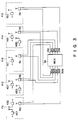
- Fig. 8 shows a detailed arrangement of each of the portable radio transceivers Ka1 to Ke1 used in the system shown in Fig. 3.
- Each transceiver includes a hybrid circuit 80, a transmitting/receiving antenna 81, a receiving section 82, and a transmitting section 83.
- the receiving section 82 includes a tuner 87, a detector 84, a call code detector 86, and a channel selecting circuit 88.
- the tuner 87 is constituted by 10 resonators respectively corresponding to the carrier frequencies f1 to f5 and f1′ to f5′, as shown in Fig. 8.
- the tuner 87 selectively outputs a channel selection signal from one of terminals T1 to T5′ in accordance with a received carrier frequency. For example, when a radio signal having the carrier frequency f1 is received, a channel selection signal.is output from the terminal T1 and is supplied to the channel selecting circuit 88.
- the circuit 88 Upon reception of the channel selection signal from the terminal T1, the circuit 88 turns on a lamp (not shown) for indicating that the frequency f1 is used, and at the same time, controls the tuner 87 not to receive signals other than the frequency f1 until the contents of a call code are checked by the call code detector 86. Similarly, when a channel selection signal is supplied from the terminal T2, the circuit 88 turns on a lamp (not shown) indicating that the frequency f2 is used, and at the same time, controls the tuner 87 not to receive signals other than the frequency f2 until the contents of a call code are checked by the call code detector 86.
- Such a control operation for channel selection by the channel selecting circuit 88 can be realized by various methods, e.g., a method of selectively interrupting supply of a power source voltage VC to each portion of a resonator.
- the detector 84 is used to extract a modulation signal such as a speech signal from a signal received by the tuner 87.
- the extracted modulation signal is output to a terminal 85, and at the same time, is supplied to the call code detector 86.
- the call code detector 86 has a pre-assigned self code and compares it with a call code supplied from another radio transceiver. If they coincide with each other, the detector 86 generates a signal for turning on a switch S2 of the transmitting section 83.
- the transmitting section 83 includes an oscillator 90, a transmission frequency switching circuit 89, a modulator 91, and switches S1 and S2.
- the circuit 89 is used to manually select carrier frequencies for transmission. For example, when the lamp for indicating that the carrier frequency f1 is used is turned on by the channel selecting circuit 88, the frequency f1 will not be used (since the frequency f1′ is also used, the frequency f1′ will not be used) and an unused frequency is selected.
- the modulator 91 modulates a carrier wave having a frequency selected by the circuit 89 by using a modulation signal such as a speech signal. The modulated signal is then radiated in air from the transmitting/receiving antenna 81 when one of the switches S1 and S2 is ON.
- the switch S1 is manually operated and is set in an ON state when signal transmission is to be performed.
- the switch S2 is controlled by an output signal from the call code detector 86 and is automatically set in an ON state when a call code is transmitted from another radio transceiver to its own channel.
- the private branch radio communication system of the present invention by combining a transmission medium using radio waves with a transmission medium using optical fibers, excellent communication can be provided in a wide range covering the entire premises even when a weak radio wave is used.
Description
- The present invention relates to a radio communication system including a plurality of portable radio transceivers and a plurality of two-way repeater means.
- On sites such as power plants or substations, large numbers of personnel may be engaged in jobs related to each other, but often doing so in widely separated locations throughout the site. For this reason, a radio communication system is generally used to enable personnel to communicate with each other, with each worker carrying a portable radio transceiver while doing his job, and exchanging information with other personnel, as and when required.
- This type of radio communication system utilizes a relatively weak radio wave, this being because if a strong radio wave were to be used, it might interfere with the operation of various electronic devices located on the same premises.
- If radio communication is to be performed in a building, especially in a so-called intelligent building in which various systems, such as the air conditioning system, for example, are computer-controlled, a very weak radio wave, e.g., a radio wave having a field intensity of 500 »V/m or less which is measured at, for example, a position 3 m away from a radio wave source, should preferably be used in order to prevent erroneous operation of various electronic devices in the building, as a result of radio interference. However, in buildings, the transmitting of radio waves tends to be hindered by walls, pillars, and the like. Therefore, when a weak radio wave is, for the aforestated reasons, used for communication within a building, satisfactory communication from the ground floor to the uppermost floor cannot be achieved. For this reason, radio communication using a weak radio wave can be employed only within a confined area, e.g., within one floor of a building, but not throughout all floors of the building. As a result, the range through which personnel can move and remain in communication is undesirably limited.
- Accordingly, it is an object of the present invention to provide a radio communication system which is capable of providing excellent communication between different areas of a premises such as a building without interfering with the operation of other electronic devices located in the same premises, so that the system can be used as a private branch radio communication system. This object is achieved, according to the present invention, by the features of
claim 1. A particular advantageous embodiment of the invention is described in thedependent claim 2. - Briefly stated, the invention provides for optical signal multiplexing means between a plurality of two-way repeaters for realizing communication between a plurality of portable radio transceivers via pairs of optical transmission lines. The multiplexing means according to the invention uses simple signal adding techniques.
- In particular, in the radio communication system of the invention a plurality of two-way repeater means are distributed throughout a plurality of areas and are coupled to signal multiplexing means through an optical transmission medium such as optical fiber cables. As a result, a radio signal generated from a portable radio transmitter in a first area is not transmitted directly from the first area to a second area by radio transmission, but is first converted into an optical signal by the repeater in the first area, the optical signal is then transmitted through an optical fiber cable to optical signal multiplexing means wherein the optical signal is converted into an electrical signal and then added with the respective other electical signals obtained by similar conversion of other optical signals coming from other repeaters. The added signals are converted into a combined optical signal which is transmitted to each two-way repeater for radio transmission in the respective areas.
- Since communication between the first and second areas is accomplished not by direct radio transmission but by means of an optical fiber cable, therefore even if the different areas are, for example, different floors in a building, or even different buildings, communication between the first and second areas is free from interference caused by obstacles to transmission, such as walls and pillars in the building or, in the latter case, other buildings in-between. Therefore, even when using a weak radio wave generated by a portable transmitter, the present invention is able to provide excellent private branch radio communication over a wide-ranging area.
- In addition, since an optical signal transmitted through an optical fiber cable is not an electrical signal, such a signal is therefore free from electrical influences caused by various other electrical signal lines and it, in turn, does not adversely influence such signal lines.
- It is known from JP-A-55143854 (see PATENT ABSTRACTS OF JAPAN, Vol. 5, No. 15, January 29, 1981) to use optical fibers for transmitting signals between (a) radio base stations which receive radio signals from a mobile station and (b) a line control radio base station where the optically transmitted signals are converted into sound.
- The system of the present invention is of advantage in a private branch radio communication system and, using a weak radio wave and an optical signal, provides excellent private branch radio communication while at the same time having minimal adverse influence on various other electrical devices and telephone lines.
- This invention can be more fully understood from the following detailed description when taken in conjunction with the accompanying drawings, in which:
- Fig. 1 is a block diagram showing a simplified private branch radio communication system with one-way repeaters, helpful for understanding the present invention;
- Fig. 2 is a block diagram showing a simplified private branch radio communication system with two-way repeaters, helpful for understanding the present invention;
- Fig. 3 is a block diagram showing a private branch radio communication system according to an embodiment of the present invention;
- Fig. 4 is a circuit diagram showing an embodiment of an arrangement of an optical multiplexer used in the private branch radio communication system in Fig. 3;
- Fig. 5 is a circuit diagram showing an embodiment of an arrangement of a first repeater used in the private branch radio communication system in Fig. 1;
- Fig. 6 is a circuit diagram showing an embodiment of an arrangement of a second repeater used in the private branch radio communication system in Fig. 1;
- Fig. 7 is a circuit diagram showing an embodiment of an arrangement of a repeater used in the private branch radio communication system in Fig. 3; and
- Fig. 8 is a circuit diagram showing an arrangement of a portable radio transceiver used in the private branch radio communication system in Fig. 3.
- Referring to Fig. 1, a first area P1 represents a specific place in a specific building or site, e.g., a specific floor in a building, and a second area P2 represents a place separated from the first area P1 by a relatively large distance, e.g., another floor in the same building as that of the first area P1, or another place within the same site as that of the first area P1.
- This private branch communication system is designed to transmit a radio signal generated by a
portable radio transmitter 1 used in the first area P1 to aportable radio receiver 4 used in the second area P2. In this system, theportable radio transmitter 1 and arepeater 2 are arranged in the first area P1. Theradio transmitter 1 is carried by, e.g., a worker and is freely moved in the first area P1. Therepeater 2 is fixed in a specific place of the first area P1. Similarly, theportable radio receiver 4 and arepeater 3 are arranged in the second area P2. Theradio receiver 4 can be freely moved in the second area P2, and therepeater 3 is fixed in a specific place of the second area P2. Therepeaters optical fiber cable 5. - The
portable radio transmitter 1 comprises amodulator 7 including an oscillator 6, an amplifier 8, and a transmitting antenna 9. Theradio transmitter 1 modulates a carry signal by a modulation signal to be transmitted, e.g., a speech signal by using themodulator 7, and amplifying the modulated signal by using the amplifier 8, thus radiating the amplified signal in air as a radio signal through the antenna 9. Therepeater 2 comprises areceiving antenna 10, anamplifier 11, and anoptical modulator 12. Therepeater 2 receives a radio signal output from theradio transmitter 1 through theantenna 10, amplifies the received signal by using theamplifier 11, and converts the signal into an optical signal by using theoptical modulator 12, thus supplying the signal to theoptical fiber cable 5. - The
repeater 3 comprises anoptical detector 13, anamplifier 14, and a transmittingantenna 15. Therepeater 3 converts the optical signal, which is transmitted from therepeater 2 through theoptical fiber cable 5, into an electrical signal by using theoptical detector 13, and amplifies the electrical signal by using theamplifier 14, thereby radiating the amplified signal in air as a radio signal through theantenna 15. Theportable radio receiver 4 comprises areceiving antenna 16, anamplifier 17, and ademodulator 18. Theradio receiver 4 receives a radio signal output from therepeater 2 through theantenna 16, and amplifies the received signal by using theamplifier 17, thereby demodulating the signal by using thedemodulator 18. As a result, the modulation signal (speech signal in this case) is extracted from the received signal. - Since both the
radio transmitter 1 and therepeater 2 are present in the first area P1, communication therebetween can be satisfactorily performed by using a weak radio wave (e.g., a radio wave having a field intensity of 500 »V/m or less which is measured at a position separated from theradio transmitter 1 by 3 m). Similarly, since both theradio receiver 4 and therepeater 3 are present in the second area P2, communication therebetween can be satisfactorily performed by using a weak radio wave (e.g., a radio wave having a field intensity of 500 »V/m or less which is measured at a position separated from therepeater 3 by 3 m). - Since signal transmission over a relatively large distance from the first area P1 to the second area P2 is performed not by radio transmission but by means of the
optical fiber cable 5, a signal from the first area P1 is transmitted to the second area P2 without loss caused by radio wave obstacles such as walls and pillars in a building, or buildings in a site. Therefore, even if a radio wave output from theradio transmitter 1 is weak, a radio signal can satisfactorily be transmitted to theradio receiver 4 in an excellent state. - In addition, since an optical signal transmitted through the
optical fiber cable 5 is not an electrical signal, the signal is free from electrical influences from various other electrical signal lines and does not influence them. - A signal to be transmitted by this private branch radio communication system is not limited to a speech signal, but may include image signals or various data signals. In addition, it may include analog or digital signals.
- Fig. 5 shows a detailed arrangement of the
repeater 2. As shown in Fig. 5, a circuit including a constant-voltage source 121 and alaser diode 122 is used as the optical modulator of therepeater 2. In this circuit, a light-emitting diode may be used in place of thelaser diode 122. - Fig. 6 shows a detailed arrangement of the
repeater 3. As shown in Fig. 6, a circuit including aphotodiode 131 is used as theoptical detector 13 of therepeater 13. - Since the
repeaters - Fig. 2 shows a private branch communication system using two-way repeaters. This system is designed to realize duplex simultaneous communication between first and second areas P1 and P2. Referring to Fig. 2, a
portable radio transceiver 21 and two-way repeater 22 are arranged in the first area P1. Theradio transceiver 21 is carried by, e.g., a worker and is moved within the first area P1. Therepeater 22 is fixed in a specific place of the first area P1. Similarly, aportable radio transceiver 24 and a two-way repeater 23 are arranged in the second area P2. Thetransceiver 24 is moved within the second area P2, and therepeater 23 is fixed in a specific place of the second area P2. Therepeaters optical fiber cables - The
portable radio transceiver 21 includes atransmitting section 21A, a receivingsection 21B, and a transmitting/receivingantenna 21C. The transmitting and receivingsections transmitter 1 and thereceiver 4 shown in Fig. 1. Theradio transceiver 21 modulates and amplifies a signal to be transmitted, e.g., a speech signal by using thetransmitting section 21A, and radiates the resultant signal in air as a radio signal having a carrier frequency f1 through theantenna 21C. In addition, theradio transceiver 21 receives a radio signal having a carrier frequency f1′ through theantenna 21C, and amplifies and demodulates the received signal by using thereceiving section 21B. As a result, the modulation signal (speech signal in this case) is extracted from the received signal. - The two-
way repeater 22 comprises a transmitting/ receivingantenna 22C, an electrical/opticalsignal converting section 22A, and an optical/electricalsignal converting section 22B. The electrical/optical convertingsection 22A and the optical/electrical modulator 22B respectively correspond to therepeaters repeater 22 receives a radio signal output from thetransceiver 21 through theantenna 22C, and converts the received signal into an optical signal by using the electrical/optical convertingsection 22A, thereby supplying the signal to theoptical fiber cable 5A. In addition, therepeater 22 converts an optical signal supplied through theoptical fiber cable 5B into an electrical signal by using the optical/electrical convertingsection 22B, and radiates the converted signal in air as a radio signal having the carrier frequency f1′ through theantenna 22C. - The two-
way repeater 23 comprises a transmitting/ receivingantenna 23C, an optical/electrical convertingsection 23A and an electrical/opticalsignal converting section 23B. The electrical/opticalsignal converting section 23B and the optical/electrical modulator 23A respectively correspond to therepeaters repeater 23 converts an optical signal supplied through theoptical fiber cable 5A into an electrical signal by using the optical/electricalsignal converting section 23A, and radiates the converted signal in air as a radio signal having the carrier frequency f1 through theantenna 23C. In addition, therepeater 23 receives a radio signal having the frequency f1′ output from thetransceiver 24 through theantenna 23C, and converts the received signal into an optical signal by using the electrical/optical convertingsection 23B, thereby supplying the signal to theoptical fiber cable 5B. - The
portable radio transceiver 24 comprises a transmitting/receivingantenna 24C, a transmittingsection 24A, and areceiving section 24B. The transmitting and receivingsections transmitter 1 and thereceiver 4 shown in Fig. 1. Theradio transceiver 24 modulates and amplifies a signal to be transmitted, e.g., a speech signal by using thetransmitting section 24A, and radiates the resultant signal in air as a radio signal having the carrier frequency f1′ through theantenna 24C. In addition, thetransceiver 24 receives a radio signal having the carrier frequency f1 through theantenna 24C, and amplifies and demodulates the received signal by using thereceiving section 24B. As a result, the modulation signal (speech signal in this case) is extracted from the received signal. - Since the private branch radio communication system of Fig. 2 employs different carrier frequencies for transmission and reception, duplex communication can be realized. In addition, since the two-
way repeaters portable transceivers - In this embodiment, the two
optical fiber cables repeaters - Fig. 3 shows a private branch radio communication system according to an embodiment of the present invention. This system is designed to realize duplex communication between arbitrary areas of a plurality of areas. In this system, the premises are divided into five areas P11 to P15. A two-way repeater and one portable radio transceiver or more are arranged in each area. More specifically, a two-way repeater Ra and two portable radio transceivers Ka1 and Ka2 are arranged in the area P11, a two-way repeater Rb and two portable radio transceivers Kb1 and Kb2 are arranged in the area P12, a two-way repeater Rc and a portable radio transceiver Kc1 are arranged in the area P13, a two-way repeater Rd and two portable radio transceivers Kd1 and Kd2 are arranged in the area P14, and a two-way repeater Re and a portable radio transceiver Ke1 are arranged in the area P15. A each range of these areas P11 to P15 is setting so that a weak radio wave can sufficiently propagate in the each area.
- The repeater Ra is coupled to transmitting and receiving
optical fiber cables optical fiber cables - An
optical multiplexer 32 includes input ports coupled to theoptical fiber cables 30a to 30e, and output ports coupled to theoptical fiber cables 31a to 31e. Themultiplexer 32 multiplexes all the optical signal supplied through thecables 30a to 30e, and outputs a multiplexed signal to theoptical fiber cables 31a to 31e, respectively. - An operation of the above-described system will be described below. Assume that ten frequencies f1 to f5 and f1′ to f5′ are respectively assigned to the transceivers Ka1 to Ke1. In this system, if a specific portable radio transceiver transmits a radio signal having the frequency f1, another portable radio transceiver which receives the signal sends back a radio signal having the frequency f1′ as a response signal. Therefore, in this system, five channels allowing simultaneous communication are ensured, i.e., a first channel using the frequencies f1 and f1′, a second channel using the frequencies f2 and f2′, a third channel using the frequencies f3 and f3′, a fourth channel using the frequencies f4 and f4′, and a fifth channel using the frequencies f5 and f5′.
- Each of the radio transceivers Ka1 to Ke1 can radiate a radio signal having any one of the frequencies f1 to f5 and f1′ to f5′, and can receive a radio signal having any of the frequencies f1 to f5 and f1′ to f5′. In addition, each of the units Ka1 to Ke1 has a function of detecting a frequency used by another unit. With this function, each of the units Ka1 to Ke1 can output a radio signal by using an unused frequency, i.e., a free channel, thus preventing radio interference.
- Speech communication using the system shown in Fig. 3 will be described below in a state wherein all of the above-described first to fifth channels are used.
- Radio signals generated by this system are ten signals denoted by V1 to V5 and V1′ to V5′ respectively corresponding to the carrier frequencies f1 to f5 and f1′ and f5′. If these radio signals V1 to V5 and V1′ to V5′ are signals having amplitude-modified waves, the radio signals V1 to V5 and V1′ to V5′ can be represented as follows:
V1 = A(1 + si(t)sin(2πf1t))
V2 = A(1 + sj(t)sin(2πf2t))
V3 = A(1 + sk(t)sin(2πf3t))
V4 = A(1 + sp(t)sin(2πf4t))
V5 = A(1 + sq(t)sin(2πf5t))
V1′ = A(1 + si′(t)sin(2πf1′t))
V2′ = A(1 + sj′(t)sin(2πf2′t))
V3′ = A(1 + sk′(t)sin(2πf3′t))
V4′ = A(1 + sp′(t)sin(2πf4′t))
V5′ = A(1 + sq′(t)sin(2πf5′t))
where A is a constant and si(t), sj(t), sk(t), sp(t), sq(t), si′(t), sj′(t), sk′(t), sp′(t), and sq′(t) are modulation signals such as speech signals. For example, with respect to the radio signal V1 for speech communication which is transmitted from a given transceiver, the radio signal V1′ is sent back from another transceiver as a response signal. Similarly, with respect to the radio signals V2, V3, V4, and V5, the radio signals V2′, V3′, V4′ and V5′ are respectively sent back as response signals. - When the radio signals V1 to V5 are respectively generated in the areas P11 to P15, these signals are respectively converted into optical signals by the repeaters Ra to Re so as to be transmitted to the
optical fiber cables 30a to 30e. The signals V1 to V5 are multiplexed by theoptical multiplexer 32, and the multiplexed signal V1 + V2 + V3 + V4 + V5 is supplied to theoptical fiber cables 31a to 31e. As a result, the multiplexed signals V1 + V2 + V3 + V4 + V5 are received by the repeaters Ra to Re. Thereafter, the multiplexed signals V1 + V2 + V3 + V4 + V5 are generated as radio signals in the areas P11 to P15. - In this manner, a signal transmitted from each portable radio transceiver is commonly supplied to the respective areas P11 to P15. Since the transceivers Ka1 to Ke1 can receive radio signals of all the frequencies, a transceiver as a source, i.e., a source operator must specify a transceiver as a destination, i.e., a destination operator. If the source operator transmits a signal for specifying a destination operator, e.g., a specific call code like a telephone number prior to transmission of a radio signal for speech communication in the same manner as in a known normal paging system, this problem can be solved. More specifically, the source operator superposes a call signal for specifying a destination operator on the frequency of a free channel (one of the frequencies f1, f2, f3, f4, and f5) and transmits it. Since the call signal is distributed to all the areas P11 to P15, a destination operator in any area can receiver the call signal.
- When a specific portable radio transceiver calls another specific portable radio transceiver in this manner, the called transceiver sends back a response signal. In this case, if the call signal has the carrier frequency f1, the called radio transceiver sends back the response signal V1′ having the carrier frequency f1′. Similarly, the response signal V2′ having the carrier frequency f2′ is sent back with respect to a call signal having carrier frequency f2.
- Similar to the above-described transmission signals V1 to V5, the response signals V1′ to V5′ thus generated are supplied to the
optical multiplexer 32 through theoptical fiber cables 30a to 30e and are multiplexed by themultiplexer 32. The multiplexed signal V1′ + V2′ + V3′ + V4′ + V5′ is commonly supplied to all the areas P11 to P12. - As described above, in the system of the invention, since transmission signals from the respective areas are multiplexed by the
optical multiplexer 32, and the multiplexed signal is supplied to all the areas, duplex communication can be performed between arbitrary areas. - Fig. 4 shows a detailed arrangement of the
optical multiplexer 32. Themultiplexer 32 comprises optical/electrical signal converters 33a to 33e, anadder 34 including resistors R1a to R1e and R2, anamplifier 36, and electrical/optical signal converters 35a to 35e. In theoptical multiplexer 32 having the above arrangement, the signals V1 to V5 input as optical signals are respectively converted into electrical signals by theconverters 33a to 33e, and are added to each other by theadder 34. The added signal V1 + V2 + V3 + V4 + V5 is amplified by theamplifier 36. The amplified signal is then supplied toconverters 35a to 35e, and hence the signals V1 + V2 + V3 + V4 + V5 are supplied to theoptical fiber cables 31a to 31e as optical signals, respectively. - Fig. 7 shows a detailed arrangement of each of the repeaters Ra to Re used in the system shown in Fig. 3. Since the repeaters Ra to Re have the same arrangement, Fig. 7 shows an arrangement corresponding to the repeater Ra. Referring to Fig. 7, a transmitting/receiving
antenna 72, a receiving section including anamplifier 73 and an electrical/optical signal converter 74, and a transmitting section including anamplifier 78 and an optical/electrical signal converter 77 are coupled to ahybrid circuit 71. Anoptical fiber cable 30a is coupled to the electrical/optical signal converter 74. Anoptical fiber cable 31a is coupled to the optical/electrical signal converter 77. Theamplifiers hybrid circuit 71 is designed to cause a signal to flow in a direction indicated by a solid arrow and not to flow in a direction indicated by a broken arrow. - Fig. 8 shows a detailed arrangement of each of the portable radio transceivers Ka1 to Ke1 used in the system shown in Fig. 3. Each transceiver includes a
hybrid circuit 80, a transmitting/receivingantenna 81, a receivingsection 82, and a transmittingsection 83. - The receiving
section 82 includes atuner 87, adetector 84, acall code detector 86, and achannel selecting circuit 88. Thetuner 87 is constituted by 10 resonators respectively corresponding to the carrier frequencies f1 to f5 and f1′ to f5′, as shown in Fig. 8. Thetuner 87 selectively outputs a channel selection signal from one of terminals T1 to T5′ in accordance with a received carrier frequency. For example, when a radio signal having the carrier frequency f1 is received, a channel selection signal.is output from the terminal T1 and is supplied to thechannel selecting circuit 88. Upon reception of the channel selection signal from the terminal T1, thecircuit 88 turns on a lamp (not shown) for indicating that the frequency f1 is used, and at the same time, controls thetuner 87 not to receive signals other than the frequency f1 until the contents of a call code are checked by thecall code detector 86. Similarly, when a channel selection signal is supplied from the terminal T2, thecircuit 88 turns on a lamp (not shown) indicating that the frequency f2 is used, and at the same time, controls thetuner 87 not to receive signals other than the frequency f2 until the contents of a call code are checked by thecall code detector 86. Such a control operation for channel selection by thechannel selecting circuit 88 can be realized by various methods, e.g., a method of selectively interrupting supply of a power source voltage VC to each portion of a resonator. - The
detector 84 is used to extract a modulation signal such as a speech signal from a signal received by thetuner 87. The extracted modulation signal is output to a terminal 85, and at the same time, is supplied to thecall code detector 86. Thecall code detector 86 has a pre-assigned self code and compares it with a call code supplied from another radio transceiver. If they coincide with each other, thedetector 86 generates a signal for turning on a switch S2 of the transmittingsection 83. - The transmitting
section 83 includes anoscillator 90, a transmissionfrequency switching circuit 89, amodulator 91, and switches S1 and S2. Thecircuit 89 is used to manually select carrier frequencies for transmission. For example, when the lamp for indicating that the carrier frequency f1 is used is turned on by thechannel selecting circuit 88, the frequency f1 will not be used (since the frequency f1′ is also used, the frequency f1′ will not be used) and an unused frequency is selected. Themodulator 91 modulates a carrier wave having a frequency selected by thecircuit 89 by using a modulation signal such as a speech signal. The modulated signal is then radiated in air from the transmitting/receivingantenna 81 when one of the switches S1 and S2 is ON. The switch S1 is manually operated and is set in an ON state when signal transmission is to be performed. The switch S2 is controlled by an output signal from thecall code detector 86 and is automatically set in an ON state when a call code is transmitted from another radio transceiver to its own channel. - As has been described above, according to the private branch radio communication system of the present invention, by combining a transmission medium using radio waves with a transmission medium using optical fibers, excellent communication can be provided in a wide range covering the entire premises even when a weak radio wave is used.
Claims (2)
- A radio communication system including a plurality of portable radio transceivers (Ka1-Ke1) and a plurality of two-way repeater means (Ra-Re), characterized by:
said two-way repeater means (Ra-Re) being distributed throughout a plurality of areas (P11-P15) within a given premises, for receiving radio signals generated in the respective areas where the repeater means are distributed and supplying optical signals corresponding to the signals received to a plurality of first optical transmission media (30a-30e), and for receiving optical signals input through a plurality of second optical transmission media (31a-31e) and generating radio signals corresponding to the signals received in the respective areas; and
optical signal multiplexing means including optical to electrical signal converting means (33a-33e) for converting, into electrical signals, optical signals transmitted through said plurality of first optical transmission media (30a-30e), adding means (34) for adding said electrical signals converted by said optical to electrical converting means (33a-33e), electrical to optical converting means (35a-35e) for converting said added electrical signals into an optical signal, and supplying the optical signal to said plurality of second optical transmission media (31a-31e). - A system according to claim 1, characterized in that said plurality of portable radio transceivers (Ka1-Ke1) are distributed throughout said plurality of areas (P11-P15).
Applications Claiming Priority (2)
| Application Number | Priority Date | Filing Date | Title |
|---|---|---|---|
| JP148237/88 | 1988-06-17 | ||
| JP63148237A JPH022727A (en) | 1988-06-17 | 1988-06-17 | Radio wave transmission/reception system via optical fiber |
Publications (3)
| Publication Number | Publication Date |
|---|---|
| EP0346925A2 EP0346925A2 (en) | 1989-12-20 |
| EP0346925A3 EP0346925A3 (en) | 1991-08-21 |
| EP0346925B1 true EP0346925B1 (en) | 1995-04-05 |
Family
ID=15448314
Family Applications (1)
| Application Number | Title | Priority Date | Filing Date |
|---|---|---|---|
| EP89110993A Expired - Lifetime EP0346925B1 (en) | 1988-06-17 | 1989-06-16 | Private branch radio communication system using optical fibers |
Country Status (4)
| Country | Link |
|---|---|
| US (1) | US5159479A (en) |
| EP (1) | EP0346925B1 (en) |
| JP (1) | JPH022727A (en) |
| DE (1) | DE68922023T2 (en) |
Cited By (7)
| Publication number | Priority date | Publication date | Assignee | Title |
|---|---|---|---|---|
| US7962111B2 (en) | 2002-02-25 | 2011-06-14 | ADC Wireless, Inc. | Distributed automatic gain control system |
| US8583100B2 (en) | 2007-01-25 | 2013-11-12 | Adc Telecommunications, Inc. | Distributed remote base station system |
| US8737454B2 (en) | 2007-01-25 | 2014-05-27 | Adc Telecommunications, Inc. | Modular wireless communications platform |
| US9001811B2 (en) | 2009-05-19 | 2015-04-07 | Adc Telecommunications, Inc. | Method of inserting CDMA beacon pilots in output of distributed remote antenna nodes |
| US9577922B2 (en) | 2014-02-18 | 2017-02-21 | Commscope Technologies Llc | Selectively combining uplink signals in distributed antenna systems |
| US10505635B2 (en) | 2000-07-19 | 2019-12-10 | Commscope Technologies Llc | Point-to-multipoint digital radio frequency transport |
| USRE49377E1 (en) | 2002-12-03 | 2023-01-17 | Commscope Technologies Llc | Distributed digital antenna system |
Families Citing this family (34)
| Publication number | Priority date | Publication date | Assignee | Title |
|---|---|---|---|---|
| CA2008900C (en) * | 1989-04-04 | 1998-01-20 | Ta-Shing Chu | Optical fiber microcellular mobile radio |
| AU628710B2 (en) * | 1990-02-01 | 1992-09-17 | Alcatel N.V. | Cellular mobile radio system |
| IT1248925B (en) * | 1990-05-31 | 1995-02-11 | Sirti Spa | Repeater for telecommunications, particularly for radio telephony |
| US5241410A (en) * | 1990-06-21 | 1993-08-31 | Litephone Systems Ltd. | Enhanced infrared-connected telephone system |
| JP2897492B2 (en) * | 1991-10-24 | 1999-05-31 | 日本電気株式会社 | Mobile communication device |
| GB2268653B (en) * | 1991-12-16 | 1995-08-30 | Motorola Inc | Optical distribution system |
| KR930020867A (en) * | 1992-03-02 | 1993-10-20 | 빈센트 비.인그라시아 | Remote Sensing Units and Drivers |
| US5339184A (en) * | 1992-06-15 | 1994-08-16 | Gte Laboratories Incorporated | Fiber optic antenna remoting for multi-sector cell sites |
| US5627879A (en) * | 1992-09-17 | 1997-05-06 | Adc Telecommunications, Inc. | Cellular communications system with centralized base stations and distributed antenna units |
| EP0674452B1 (en) * | 1994-03-24 | 2002-07-03 | Hitachi Kokusai Electric Inc. | Repeater for radio paging system |
| EP0772924B1 (en) * | 1994-03-30 | 2002-01-23 | BRITISH TELECOMMUNICATIONS public limited company | Generation of radio frequency modulated optical radiation |
| US5809840A (en) * | 1995-02-14 | 1998-09-22 | Shimano, Inc. | Protective cap system for bicycle cable |
| EP0805569B1 (en) * | 1995-08-23 | 2004-04-21 | Ntt Mobile Communications Network Inc. | Optical fiber transmission system |
| EP0762674A3 (en) * | 1995-09-08 | 2001-03-21 | Siemens Aktiengesellschaft | Method and circuit to transmit received signals from an antenna to a base station of a radio system |
| KR100221289B1 (en) * | 1996-11-21 | 1999-09-15 | 서평원 | Transceiver antenna device for shadow area in cdma |
| KR100221287B1 (en) * | 1996-11-21 | 1999-09-15 | 서평원 | Distributed transceiver antenna device for shadow area in cdma |
| US6112086A (en) | 1997-02-25 | 2000-08-29 | Adc Telecommunications, Inc. | Scanning RSSI receiver system using inverse fast fourier transforms for a cellular communications system with centralized base stations and distributed antenna units |
| JP2000147306A (en) * | 1998-08-31 | 2000-05-26 | Kokusai Electric Co Ltd | Wavelength region multiple light beam star coupler, communication station and light transmission system |
| KR20000042660A (en) * | 1998-12-26 | 2000-07-15 | 서평원 | Method for controling gain of optical repeating system |
| JP2002185490A (en) * | 2000-12-19 | 2002-06-28 | Denso Corp | Communication system and terminal apparatus |
| US7263293B2 (en) | 2002-06-10 | 2007-08-28 | Andrew Corporation | Indoor wireless voice and data distribution system |
| US20040017785A1 (en) * | 2002-07-16 | 2004-01-29 | Zelst Allert Van | System for transporting multiple radio frequency signals of a multiple input, multiple output wireless communication system to/from a central processing base station |
| US7103377B2 (en) | 2002-12-03 | 2006-09-05 | Adc Telecommunications, Inc. | Small signal threshold and proportional gain distributed digital communications |
| US7171244B2 (en) | 2002-12-03 | 2007-01-30 | Adc Telecommunications, Inc. | Communication system and method with gain control for signals from distributed antennas |
| US7599711B2 (en) * | 2006-04-12 | 2009-10-06 | Adc Telecommunications, Inc. | Systems and methods for analog transport of RF voice/data communications |
| US8873585B2 (en) | 2006-12-19 | 2014-10-28 | Corning Optical Communications Wireless Ltd | Distributed antenna system for MIMO technologies |
| WO2008109845A2 (en) | 2007-03-07 | 2008-09-12 | Becton, Dickinson And Company | Safety blood collection assembly with indicator |
| EP1988650B1 (en) | 2007-05-04 | 2012-09-05 | Mitsubishi Electric R&D Centre Europe B.V. | Radio over fibre transducer and transmission system |
| EP2832012A1 (en) | 2012-03-30 | 2015-02-04 | Corning Optical Communications LLC | Reducing location-dependent interference in distributed antenna systems operating in multiple-input, multiple-output (mimo) configuration, and related components, systems, and methods |
| WO2014085115A1 (en) | 2012-11-29 | 2014-06-05 | Corning Cable Systems Llc | HYBRID INTRA-CELL / INTER-CELL REMOTE UNIT ANTENNA BONDING IN MULTIPLE-INPUT, MULTIPLE-OUTPUT (MIMO) DISTRIBUTED ANTENNA SYSTEMS (DASs) |
| US9525472B2 (en) | 2014-07-30 | 2016-12-20 | Corning Incorporated | Reducing location-dependent destructive interference in distributed antenna systems (DASS) operating in multiple-input, multiple-output (MIMO) configuration, and related components, systems, and methods |
| US9729267B2 (en) | 2014-12-11 | 2017-08-08 | Corning Optical Communications Wireless Ltd | Multiplexing two separate optical links with the same wavelength using asymmetric combining and splitting |
| US10499269B2 (en) | 2015-11-12 | 2019-12-03 | Commscope Technologies Llc | Systems and methods for assigning controlled nodes to channel interfaces of a controller |
| US10277331B1 (en) * | 2018-04-03 | 2019-04-30 | T-Mobile Usa, Inc. | Conversion of RF signals to optical signals for passage through impairment mediums in a wireless communication network |
Family Cites Families (7)
| Publication number | Priority date | Publication date | Assignee | Title |
|---|---|---|---|---|
| DE2144676B2 (en) * | 1971-09-07 | 1975-07-31 | Licentia Patent-Verwaltungs-Gmbh, 6000 Frankfurt | Messaging system |
| JPS54113205A (en) * | 1978-02-24 | 1979-09-04 | Daido Shingo | Communication transmitting device and method |
| JPS55143854A (en) * | 1979-04-26 | 1980-11-10 | Nippon Telegr & Teleph Corp <Ntt> | Mobile radio space diversity system using optical fiber |
| US4539706A (en) * | 1983-02-03 | 1985-09-03 | General Electric Company | Mobile vehicular repeater system which provides up-link acknowledgement signal to portable transceiver at end of transceiver transmission |
| US4941207A (en) * | 1984-05-01 | 1990-07-10 | Nihon Musen Kabushiki Kaisha | Structure for wireless communication in an electromagnetically shielded building |
| EP0230406A1 (en) * | 1985-08-01 | 1987-08-05 | International Robotic Engineering Inc. | Device for the simultaneous transmission of a plurality of electric signals between two locations |
| US4991925A (en) * | 1988-10-04 | 1991-02-12 | Metricor | Spectrum shifting optical switch |
-
1988
- 1988-06-17 JP JP63148237A patent/JPH022727A/en active Pending
-
1989
- 1989-06-16 EP EP89110993A patent/EP0346925B1/en not_active Expired - Lifetime
- 1989-06-16 DE DE68922023T patent/DE68922023T2/en not_active Expired - Fee Related
-
1992
- 1992-03-05 US US07/845,356 patent/US5159479A/en not_active Expired - Fee Related
Cited By (8)
| Publication number | Priority date | Publication date | Assignee | Title |
|---|---|---|---|---|
| US10505635B2 (en) | 2000-07-19 | 2019-12-10 | Commscope Technologies Llc | Point-to-multipoint digital radio frequency transport |
| US7962111B2 (en) | 2002-02-25 | 2011-06-14 | ADC Wireless, Inc. | Distributed automatic gain control system |
| USRE49377E1 (en) | 2002-12-03 | 2023-01-17 | Commscope Technologies Llc | Distributed digital antenna system |
| US8583100B2 (en) | 2007-01-25 | 2013-11-12 | Adc Telecommunications, Inc. | Distributed remote base station system |
| US8737454B2 (en) | 2007-01-25 | 2014-05-27 | Adc Telecommunications, Inc. | Modular wireless communications platform |
| US9585193B2 (en) | 2007-01-25 | 2017-02-28 | Commscope Technologies Llc | Modular wireless communications platform |
| US9001811B2 (en) | 2009-05-19 | 2015-04-07 | Adc Telecommunications, Inc. | Method of inserting CDMA beacon pilots in output of distributed remote antenna nodes |
| US9577922B2 (en) | 2014-02-18 | 2017-02-21 | Commscope Technologies Llc | Selectively combining uplink signals in distributed antenna systems |
Also Published As
| Publication number | Publication date |
|---|---|
| DE68922023T2 (en) | 1995-11-23 |
| US5159479A (en) | 1992-10-27 |
| EP0346925A2 (en) | 1989-12-20 |
| DE68922023D1 (en) | 1995-05-11 |
| JPH022727A (en) | 1990-01-08 |
| EP0346925A3 (en) | 1991-08-21 |
Similar Documents
| Publication | Publication Date | Title |
|---|---|---|
| EP0346925B1 (en) | Private branch radio communication system using optical fibers | |
| USRE49377E1 (en) | Distributed digital antenna system | |
| US5969837A (en) | Communications system | |
| US5615034A (en) | Optical micro cell transmission system | |
| EP0859478B1 (en) | Wireless communications systems employing free-space optical communications links | |
| USRE35736E (en) | Distributed antenna system | |
| JPH05260018A (en) | Optical transmission system for radio signal | |
| KR900007129B1 (en) | Multi user communication system | |
| JPH05183527A (en) | Opto-transceiver device | |
| KR20000074988A (en) | System and method of mobile communication using in building | |
| CA2275251A1 (en) | Wireless communications station and system | |
| NO985372D0 (en) | Spectral Scattering Communication System | |
| US4691313A (en) | Wireless talking apparatus | |
| CA2035390A1 (en) | Cellular mobile radio system | |
| JPH0448832A (en) | Optical link radio communication system | |
| EP0091271A2 (en) | Data transmission apparatus | |
| JPH04207532A (en) | Communication equipment | |
| KR20020005312A (en) | Multi-channel repeater | |
| JP3194316B2 (en) | Mobile communication system | |
| JP2005094263A (en) | Optical remote system for fixed wireless communication, center station apparatus used for same, remote station apparatus, and communication method | |
| JPH06153255A (en) | Optical fiber transmtter for radio signal | |
| JPH09233050A (en) | Radio network system and optical transmission method | |
| KR100333141B1 (en) | Transmitting and receiving interface device of CDMA base station by using optic line | |
| JP4933357B2 (en) | Optical fiber wireless access system | |
| KR20000001105A (en) | Apparatus of optical transmission within wireless telecommunication base station system |
Legal Events
| Date | Code | Title | Description |
|---|---|---|---|
| PUAI | Public reference made under article 153(3) epc to a published international application that has entered the european phase |
Free format text: ORIGINAL CODE: 0009012 |
|
| 17P | Request for examination filed |
Effective date: 19890616 |
|
| AK | Designated contracting states |
Kind code of ref document: A2 Designated state(s): DE FR GB |
|
| PUAL | Search report despatched |
Free format text: ORIGINAL CODE: 0009013 |
|
| RAP1 | Party data changed (applicant data changed or rights of an application transferred) |
Owner name: SMALL POWER COMMUNICATION SYSTEMS RESEARCH LABORAT |
|
| AK | Designated contracting states |
Kind code of ref document: A3 Designated state(s): DE FR GB |
|
| 17Q | First examination report despatched |
Effective date: 19930329 |
|
| GRAA | (expected) grant |
Free format text: ORIGINAL CODE: 0009210 |
|
| AK | Designated contracting states |
Kind code of ref document: B1 Designated state(s): DE FR GB |
|
| ET | Fr: translation filed | ||
| REF | Corresponds to: |
Ref document number: 68922023 Country of ref document: DE Date of ref document: 19950511 |
|
| PLBE | No opposition filed within time limit |
Free format text: ORIGINAL CODE: 0009261 |
|
| STAA | Information on the status of an ep patent application or granted ep patent |
Free format text: STATUS: NO OPPOSITION FILED WITHIN TIME LIMIT |
|
| 26N | No opposition filed | ||
| PGFP | Annual fee paid to national office [announced via postgrant information from national office to epo] |
Ref country code: GB Payment date: 20010613 Year of fee payment: 13 |
|
| PGFP | Annual fee paid to national office [announced via postgrant information from national office to epo] |
Ref country code: DE Payment date: 20010820 Year of fee payment: 13 |
|
| PGFP | Annual fee paid to national office [announced via postgrant information from national office to epo] |
Ref country code: FR Payment date: 20011029 Year of fee payment: 13 |
|
| REG | Reference to a national code |
Ref country code: GB Ref legal event code: IF02 |
|
| PG25 | Lapsed in a contracting state [announced via postgrant information from national office to epo] |
Ref country code: GB Free format text: LAPSE BECAUSE OF NON-PAYMENT OF DUE FEES Effective date: 20020616 |
|
| PG25 | Lapsed in a contracting state [announced via postgrant information from national office to epo] |
Ref country code: DE Free format text: LAPSE BECAUSE OF NON-PAYMENT OF DUE FEES Effective date: 20030101 |
|
| GBPC | Gb: european patent ceased through non-payment of renewal fee |
Effective date: 20020616 |
|
| PG25 | Lapsed in a contracting state [announced via postgrant information from national office to epo] |
Ref country code: FR Free format text: LAPSE BECAUSE OF NON-PAYMENT OF DUE FEES Effective date: 20030228 |
|
| REG | Reference to a national code |
Ref country code: FR Ref legal event code: ST |