EP0348726A2 - Remote control arrangement - Google Patents
Remote control arrangement Download PDFInfo
- Publication number
- EP0348726A2 EP0348726A2 EP89110681A EP89110681A EP0348726A2 EP 0348726 A2 EP0348726 A2 EP 0348726A2 EP 89110681 A EP89110681 A EP 89110681A EP 89110681 A EP89110681 A EP 89110681A EP 0348726 A2 EP0348726 A2 EP 0348726A2
- Authority
- EP
- European Patent Office
- Prior art keywords
- remote control
- address
- transmitter
- remote
- address signal
- Prior art date
- Legal status (The legal status is an assumption and is not a legal conclusion. Google has not performed a legal analysis and makes no representation as to the accuracy of the status listed.)
- Withdrawn
Links
Images

Classifications
-
- G—PHYSICS
- G08—SIGNALLING
- G08C—TRANSMISSION SYSTEMS FOR MEASURED VALUES, CONTROL OR SIMILAR SIGNALS
- G08C19/00—Electric signal transmission systems
- G08C19/16—Electric signal transmission systems in which transmission is by pulses
- G08C19/28—Electric signal transmission systems in which transmission is by pulses using pulse code
-
- H—ELECTRICITY
- H03—ELECTRONIC CIRCUITRY
- H03J—TUNING RESONANT CIRCUITS; SELECTING RESONANT CIRCUITS
- H03J9/00—Remote-control of tuned circuits; Combined remote-control of tuning and other functions, e.g. brightness, amplification
- H03J9/06—Remote-control of tuned circuits; Combined remote-control of tuning and other functions, e.g. brightness, amplification using electromagnetic waves other than radio waves, e.g. light
Definitions
- the invention relates to a remote control arrangement according to the preamble of claim 1.
- Only one of the devices in this device group contains a remote control receiver and serves as the control center for this device group.
- the other devices of the known device group are connected via remote control lines to the device of the device group containing the remote control receiver.
- the associated remote control transmitter contains on its control panel an optically delimited key group for remote control of the functions of the associated remote-controlled device for each remote-controlled device in the device group.
- the number of remote control transmitters for remote control of the remote-controllable electrical devices contained in the device group is considerably restricted.
- the large number of control elements on the remote control transmitter assigned to the device group makes it so large that it is very difficult for a user of such a remote control transmitter not technically trained in this field to use this remote control transmitter.
- the invention has for its object to ensure when using remote-controlled electrical devices that can be remote-controlled via the same remote control signals that only the selected remote-controlled device of a group of similarly remote-controlled devices is influenced.
- This object is achieved according to the invention by the features specified in the characterizing part of claim 1.
- the measures according to the invention ensure that not only a single remote control transmitter is required for a group of remotely controllable electrical devices, but also that the number of control elements on the control panel of the remote control transmitter is only insignificant, namely only by the number of control elements for selecting the remote-controlled electrical devices is increased.
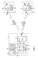
- the device group shown schematically in Fig. 1 by the circuit blocks 1, 2 and 3 consists of a remote control transmitter 1 and two remote-controlled electrical devices 2 and 3.
- the remote control transmitter 1 contains a control panel 4 with a group of button-shaped controls 5, on which a user inputs settings selected by him for the remote-controlled electrical devices 2 or 3.
- a command transmitter 6 converts these inputs into input commands EB and transmits these signals to a transmission signal generator 7 of the remote control transmitter 1.
- the control panel 4 contains a button 8, which is used to select the electrical device to be operated remotely.
- This key 8 represents a switch 9 which controls an address memory 10 in an address transmitter 11 of the remote control transmitter.
- the transmission signal generator 7 retrieves an address signal AS from the address transmitter 11, which contains the effective address A1 of the address memory 10, and uses it to form a remote control signal 12, which is formed from an address part AT and a command part BT and from a transmitter element 13 is wirelessly transmitted to the remote-controlled electrical devices 2 and 3.
- Each of the remotely controllable electrical devices 2 or 3 contains a remote control receiver 14 with a receiving element 15 which receives the wirelessly transmitted remote control signals 12 and feeds them to the remote control receiver 14.
- the remote control receiver 14 also contains an address memory 16 with the same addresses A1 and A2 as the address memory 10 of the address transmitter 11 of the remote control transmitter 1.
- the second address A2 of the address memory 16 of the remote control receiver 14 can be activated by a soldering or switching bridge 17. Without this switching bridge, the first address A1 of the address memory 16 is effective.
- the first address A1 is effective in the first remote-controllable electrical device 2 and the second address A2 is effective in the second remote-controllable electrical device 3.
- the remote control receivers 14 only evaluate the received remote control signals 12, the address part AT of which contains the address (A1, A2) which is activated in the address memory 16 of the remote control receiver 14.
- the remote control receiver 14 of the first remotely controllable electrical device 2 only evaluates remote control signals 12 whose address part AT contains the first address A1, and forms the associated commands StB for setting the first remotely controllable electrical device 2 from the command part BT of these remote control signals 12.
- FIG. 2 a further group of devices with two remotely controllable electrical devices 2 and 3 and a common remote control transmitter 18 is shown schematically by the circuit blocks 2, 3 and 18. Corresponding circuit blocks are in Figures 1 and 2 identified by the same reference numerals.
- the remote control transmitter 1a of the device group shown in FIG. 2 differs from the remote control transmitter 1 shown in FIG.
- the remotely controllable electrical device 2 or 3 to be operated remotely must first be selected by pressing one of the selection buttons 18, 19 or 20. If this selection is made, all subsequent setting commands with the selected address (for example A1) for the remote control signal 12 are completed in the transmission signal generator 7.
- the remote control receivers 14a of the remotely controllable electrical devices 2 and 3 contain an address memory 25 which, in the unprogrammed state, contains no address.
- the address A1 or A2 characterizing the remote control receiver is entered into this address memory 25 by a program sequence 26 triggered in the remote control receiver 14a and contained in the remote control receiver, during which the address A1 or A2 or A3 characterizing the remote control receiver 14a is input is stored in the address memory 25.
- the addresses A1 or A2 or A3 stored in the address memory 25 of a remote control receiver 14a must of course match one of the addresses of the address transmitter 11 of the remote control transmitter 1a stored in the address memory 10.
- the triggering of the program sequence 26 in the remote control receiver 14a and the input of the address characterizing the remote control receiver can be entered, for example, by means of existing control elements 27 and 28 of the local control of the remote-controlled electrical devices 2 and 3, so that no additional setting elements on the remote-controlled electrical devices are required for this and the triggering of the program sequence 26 is triggered only by the actuation of a specific combination of these operating elements 27, 28.
Abstract
Description
Die Erfindung betrifft eine Fernbedienungsanordnung nach dem Oberbegriff des Anspruches 1.The invention relates to a remote control arrangement according to the preamble of claim 1.
Bei der immer größer werdenden Anzahl fernbedienbarer Geräte in einem Haushalt und der unterschiedlichen Übertragungssysteme für die Übertragung der Fernbedienungssignale wird auch die Anzahl der in einem Haushalt befindlichen Fernbedienungsgeber so groß, daß die Zuordnung der Fernbedienungsgeber zu einzelnen fernbedienbaren Geräten vom Benutzer nicht mehr überschaubar ist. Deshalb besteht das Bestreben, mehrere fernbedienbare elektrische Geräte zu einer Gerätegruppe zusammenzufassen, die von einem einzigen Fernbedienungsgeber erfaßt und eingestellt werden kann. So ist es beispielsweise aus der Zeitschrift Funkschau 1985, Heft 18, Seiten 54 bis 58 bekannt, Fernsehgeräte und Videorecorder eines Herstellers mit einer einzigen Fernbedienung zu betätigen. Bei einer anderen, aus der Funkschau 1982, Heft 10, Seiten 63 bis 66 bekannten Rundfunkempfangs- und -wiedergabeanlage sind fünf fernbedienbare elektrische Geräte zu einer Gerätegruppe zusammengeschlossen. Nur eines der Geräte dieser Gerätegruppe enthält einen Fernbedienungsempfänger und dient als Steuerzentrale dieser Gerätegruppe. Die übrigen Geräte der bekannten Gerätegruppe sind über Fernsteuerleitungen an das den Fernbedienungsempfänger enthaltende Gerät der Gerätegruppe angeschlossen. Der zugehörige Fernbedienungsgeber enthält auf seinem Bedienungsfeld für jedes fernbedienbare Gerät der Gerätegruppe eine optisch abgegrenzte Tastengruppe zur Fernbedienung der Funktionen des zugehörigen fernbedienbaren Gerätes. Durch diese Maßnahme ist zwar die Zahl der Fernbedienungsgeber zur Fernbedienung der in der Gerätegruppe enthaltenen fernbedienbaren elektrischen Geräte wesentlich eingeschränkt. Andererseits wird jedoch durch die Vielzahl der Bedienungselemente auf dem der Gerätegruppe zugeordneten Fernbedienungsgeber so groß, daß einem auf diesem Fachgebiet technisch nicht vorgebildeten Benutzer eines derartigen Fernbedienungsgebers die Benutzung dieses Fernbedienungsgebers sehr erschwert ist.With the increasing number of remote-controlled devices in a household and the different transmission systems for the transmission of remote control signals, the number of remote-control transmitters in a household also becomes so large that the assignment of the remote control transmitters to individual remote-controlled devices is no longer manageable by the user. Therefore, there is a desire to combine several remote-controlled electrical devices into a group of devices that can be detected and set by a single remote control transmitter. For example, it is known from the magazine Funkschau 1985,
Andererseits tritt es immer häufiger auf, daß in einem Haushalt ein fernbedienbares elektrisches Gerät mehrfach vorhanden ist und der Benutzer beabsichtigt, diese gleichartigen fernbedienbaren elektrischen Geräte zeitlich überlappend fernzubedienen. Wird beispielsweise in einem Haushalt ein Videorecorder augenblicklich zur Wiedergabe einer Videokassette verwendet und gleichzeitig ein zweiter Videorecorder desselben Herstellers zur Aufnahme einer Videosendung verwendet, besteht die Gefahr, daß das eine Gerät durch die Bedienung des Fernbedienungsgebers des anderen Gerätes beeinflußt und in falsche Funktionen eingestellt wird.On the other hand, it occurs more and more frequently that a remote-controlled electrical device is present in a household several times and the user intends to operate these similar remote-controlled electrical devices remotely overlapping in time. If, for example, a video recorder is currently used in a household to play a video cassette and at the same time a second video recorder from the same manufacturer is used to record a video broadcast, there is a risk that one device may operate the remote control transmitter of the other device influenced and set in wrong functions.
Der Erfindung liegt die Aufgabe zugrunde, bei einer Verwendung von fernbedienbaren elektrischen Geräten, die über die gleichen Fernbedienungssignale fernbedienbar sind, zu gewährleisten, daß nur das ausgewählte fernbedienbare Gerät einer Gruppe gleichartig fernbedienbarer Geräte beinflußt wird. Diese Aufgabe wird nach der Erfindung durch die im kennzeichnenden Teil des Anspruches 1 angegebenen Merkmale gelöst.The invention has for its object to ensure when using remote-controlled electrical devices that can be remote-controlled via the same remote control signals that only the selected remote-controlled device of a group of similarly remote-controlled devices is influenced. This object is achieved according to the invention by the features specified in the characterizing part of claim 1.
Durch die Maßnahmen nach der Erfindung wird erreicht, daß für eine Gruppe gleichartig fernbedienbarer elektrischer Geräte nicht nur ein einziger Ferbedienungsgeber erforderlich ist, sondern daß auch die Anzahl der Bedienungselemente auf dem Bedienungsfeld des Fernbedienungsgebers nur unwesentlich, nämlich nur um die Anzahl der Bedienungselemente zur Auswahl der fernbedienbaren elektrischen Geräte erhöht wird.The measures according to the invention ensure that not only a single remote control transmitter is required for a group of remotely controllable electrical devices, but also that the number of control elements on the control panel of the remote control transmitter is only insignificant, namely only by the number of control elements for selecting the remote-controlled electrical devices is increased.
Die Unteransprüche kennzeichnen vorteilhafte Ausgestaltungen der Erfindung. Sind im Adressensignalgeber des Fernbedienungsgebers einerseits und in den Fernbedienungsempfängern der über gleiche Fernbedienungssignale fernbedienbaren Geräte andererseits die gleichen auswählbaren Adressen eingespeichert, dann sind an den Fernbedienungsempfängern nur einfache oder überhaupt keine mechanischen Vorrichtungen zum Einstellen einer dem Fernbedienungsempfänger kennzeichnenden Adresse erforderlich und am Fernbedienungsgeber kann die Einstelleinrichtung zur Auswahl des einzustellenden elektrischen Gerätes ebenfalls einfach ausgestaltet werden.The subclaims characterize advantageous embodiments of the invention. If the same selectable addresses are stored in the address signal transmitter of the remote control transmitter on the one hand and in the remote control receivers of the devices that can be remote controlled via the same remote control signals on the other hand, then only simple or no mechanical devices for setting an address identifying the remote control receiver are required on the remote control receivers and the setting device can be used on the remote control transmitter Selection of the electrical device to be set can also be made simple.
Die Erfindung wird nachfolgend anhand vorteilhafter Ausführungsbeispiele näher erläutert. In den Figuren 1 und 2 der zugehörigen Zeichnungen sind zwei Fernbedienungsanordnungen als Ausführungsbeispiele der Erfindung je in einem Blockschaltbild schematisch dargestellt.The invention is explained in more detail below on the basis of advantageous exemplary embodiments. In the figures 1 and 2 of the accompanying drawings, two remote control arrangements as exemplary embodiments of the invention are each shown schematically in a block diagram.
Die in Fig. 1 schematisch durch die Schaltungsblöcke 1, 2 und 3 dargestellte Gerätegruppe besteht aus einem Fernbedienungsgeber 1 und aus zwei fernbedienbaren elektrischen Geräten 2 und 3. Der Fernbedienungsgeber 1 enthält ein Bedienungsfeld 4 mit einer Gruppe von tastenförmigen Bedienungselementen 5, an denen ein Benutzer von ihm ausgewählte Einstellungen für die fernbedienbaren elektrischen Geräte 2 oder 3 eingibt. Diese Eingaben wandelt ein Befehlsgeber 6 in Eingabebefehle EB um und überträgt diese Signale an einen Übertragungssignalgenerator 7 des Fernbedienungsgebers 1. Außerdem enthält das Bedienungsfeld 4 eine Taste 8, die zur Auswahl des fernzubedienenden elektrischen Gerätes dient. Diese Taste 8 stellt einen Schalter 9, der einen Adressenspeicher 10 in einem Adressengeber 11 des Fernbedienungsgebers steuert. Im offenen Zustand des Schalters 9 ist eine erste Adresse A1 wirksam, im geschlossenen Zustand des Schalters 9 ist eine zweite Adresse A2 des Adressenspeichers 10 wirksam. Beim Empfang eines Eingabebefehles EB ruft der Übertragungssignalgenerator 7 vom Adressengeber 11 ein Adressensignal AS ab, das die wirksame Adresse A1 des Adressenspeichers 10 enthält, und bildet daraus ein Fernbedienungssignal 12, das aus einem Adressenteil AT und einem Befehlsteil BT gebildet ist und von einem Senderelement 13 drahtlos an die fernbedienbaren elektrischen Geräte 2 und 3 übertragen wird.The device group shown schematically in Fig. 1 by the circuit blocks 1, 2 and 3 consists of a remote control transmitter 1 and two remote-controlled electrical devices 2 and 3. The remote control transmitter 1 contains a control panel 4 with a group of button-
Jedes der fernbedienbaren elektrischen Geräte 2 oder 3 enthält einen Fernbedienungsempfänger 14 mit einem Empfangselement 15, das die drahtlos übertragenen Fernbedienungssignale 12 empfängt und dem Fernbedienungsempfänger 14 zuführt. Der Fernbedienungsempfänger 14 enthält ebenfalls einen Adressenspeicher 16 mit den gleichen Adressen A1 und A2 wie der Adressenspeicher 10 des Adressengebers 11 des Fernbedienungsgebers 1. Die zweite Adresse A2 des Adressenspeichers 16 des Fernbedienungsempfängers 14 kann durch eine Löt- oder Schaltbrücke 17 wirksam geschaltet werden. Ohne diese Schaltbrücke ist die erste Adresse A1 des Adressenspeichers 16 wirksam. In dem in Fig. 1 dargestellten Ausführungsbeispiel ist im ersten fernbedienbaren elektrischen Gerät 2 die erste Adresse A1 wirksam und im zweiten fernbedienbaren elektrischen Gerät 3 die zweite Adresse A2 wirksam. Die Fernbedienungsempfänger 14 werten nur die empfangenen Fernbedienungssignale 12 aus, deren Adressenteil AT die Adresse (A1, A2) enthält , die im Adressenspeicher 16 des Fernbedienungsempfänger 14 wirksam geschaltet ist. Dadurch wertet der Fernbedienungsempfänger 14 des ersten fernbedienbaren elektrischen Gerätes 2 nur Fernbedienungssignale 12 aus, deren Adressenteil AT die erste Adresse A1 enthalten, und bildet aus dem Befehlsteil BT dieser Fernbedienungssignale 12 die zugehörigen Befehle StB zur Einstellung des ersten fernbedienbaren elektrischen Gerätes 2.Each of the remotely controllable electrical devices 2 or 3 contains a
In Fig. 2 ist eine weitere Gerätegruppe mit zwei fernbedienbaren elektrischen Geräten 2 und 3 und einem gemeinsamen Fernbedienungsgeber 18 schematisch durch die Schaltungsbblöcke 2, 3 und 18 dargestellt. Sich entsprechende Schaltungsblöcke sind in den Figuren 1 und 2 durch gleiche Bezugszeichen gekennzeichnet. Der Fernbedienungsgeber 1a der in Fig. 2 dargestellten Gerätegruppe unterscheidet sich von dem in Fig. 1 dargestellten Fernbedienungsgebers 1 im wesentlichen dadurch, daß das Bedienungsfeld für jedes vom Fernbedienungsgeber aus anwählbare und fernbedienbare elektrische Gerät 2, 3, eine Auswahltaste 18, 19, 20, von den Auswahltasten betätigbare Schalter 21, 22 und 23 und einen Tastenspeicher 24 enthält, der die Betätigung der zuletzt betätigten Auswahltaste (z.B. 21) speichert und die dem zuletzt betätigten Schalter zugeordnete Adresse (z.B. A1) des Adressenspeichers 10 im Adressengeber 11 so lange wirksam schaltet, bis ein anderer Schalter 22 oder 23 betätigt wird. Vor einer Fernbedienung der fernbedienbaren elektrischen Geräte 2 oder 3 mittels der Einstellelemente 5 des Bedienungsfeldes 4 des Fernbedienungsgebers 1a muß zuerst durch Betätigen einer der Auswahltasten 18, 19 oder 20 das fernbedienbare elektrische Gerät 2 oder 3 ausgewählt werden, das fernbedient werden soll. Ist diese Auswahl getroffen, werden in dem Übertragungssignalgenerator 7 alle nachfolgenden Einstellbefehle mit der ausgewählten Adresse (z.B. A1) zum Fernbedienungssignal 12 vervollständigt.In Fig. 2, a further group of devices with two remotely controllable electrical devices 2 and 3 and a common
Die Fernbedienungsempfänger 14a der fernbedienbaren elektrischen Geräte 2 und 3 enthalten einen Adressenspeicher 25, der im unprogrammierten Zustand keine Adresse enthält. In diesen Adressenspeicher 25 wird die den Fernbedienungsempfänger kennzeichnende Adresse A1 oder A2 durch einen am Fernbedienungsempfänger 14a ausgelösten, im Fernbedienungsempfänger enthaltenen Programmablauf 26, während dem die den Fernbedienungsempfänger 14a kennzeichnende Adresse A1 oder A2 oder A3 eingegeben wird, in den Adressenspeicher 25 eingespeichert. Die in den Adressenspeicher 25 eines Fernbedienungsempfängers 14a eingespeicherten Adressen A1 oder A2 oder A3 müssen natürlich mit einer der in dem Adressenspeicher 10 eingespeicherten Adressen des Adressengebers 11 des Fernbedienungsgebers 1a übereinstimmen. Die Auslösung des Programmablaufes 26 im Fernbedienungsempfänger 14a und die Eingabe der den Fernbedienungsempfänger kennzeichnenden Adresse kann beispielsweise mittels schon vorhandener Bedienungselemente 27 und 28 der Ortsbedienung der fernbedienbaren elektrischen Geräte 2 und 3 eingegeben werden, so daß hierzu keine zusätzlichen Einstellelemente an den fernbedienbaren elektrischen Geräten erforderlich sind und das Auslösen des Programmablaufes 26 lediglich durch die Betätigung einer bestimmten Kombination dieser Bedienungselemente 27, 28 ausgelöst wird.The
Claims (4)
dadurch gekennzeichnet,
- daß jedes elektrische Gerät (2, 3) der Gruppe einen Fernbedienungsempfänger (14, 14a) zum Empfang der drahtlos übertragenen Fernbedienungssignale (12) enthält,
- daß jeder Fernbedienungsempfänger eine Vorrichtung (17, 26) zum Einstellen einer den Fernbedienungsempfänger kennzeichnenden Adresse (A1, A2) enthält und nur die Fernbedienungssignale auswertet, die als Signalbestandteil (AT) die am Fernbedienungsempfänger eingestellte Adresse enthalten,
- und daß der Fernbedienungsgeber (1, 1a). eine Einstelleinrichtung (8, 18, 19, 20) zur Auswahl des einzustellenden elektrischen Gerätes enthält, mit deren Einstellung an einem im Fernbedienungsgeber enthaltenen Adressensignalgeber (11) die Ausgabe des dem ausgewählten elektrischen Gerät zugeordneten Adressensignals (AS) ausgelöst wird.1. Remote control arrangement for remote control of a group of remotely controllable electrical devices by means of a remote control transmitter, which generates a remote control signal when a control command is triggered and transmits it wirelessly to a remote control receiver of one of the electrical devices,
characterized by
- that each electrical device (2, 3) in the group contains a remote control receiver (14, 14a) for receiving the wirelessly transmitted remote control signals (12),
- that each remote control receiver contains a device (17, 26) for setting an address (A1, A2) characterizing the remote control receiver and only evaluates the remote control signals which contain the address set on the remote control receiver as a signal component (AT),
- And that the remote control transmitter (1, 1a). contains a setting device (8, 18, 19, 20) for selecting the electrical device to be set, with its setting on one in the remote control transmitter contained address signal generator (11) the output of the address signal (AS) assigned to the selected electrical device is triggered.
Applications Claiming Priority (2)
| Application Number | Priority Date | Filing Date | Title |
|---|---|---|---|
| DE3821572 | 1988-06-25 | ||
| DE19883821572 DE3821572A1 (en) | 1988-06-25 | 1988-06-25 | REMOTE CONTROL ARRANGEMENT |
Publications (2)
| Publication Number | Publication Date |
|---|---|
| EP0348726A2 true EP0348726A2 (en) | 1990-01-03 |
| EP0348726A3 EP0348726A3 (en) | 1990-05-16 |
Family
ID=6357306
Family Applications (1)
| Application Number | Title | Priority Date | Filing Date |
|---|---|---|---|
| EP89110681A Withdrawn EP0348726A3 (en) | 1988-06-25 | 1989-06-13 | Remote control arrangement |
Country Status (3)
| Country | Link |
|---|---|
| EP (1) | EP0348726A3 (en) |
| JP (1) | JPH0272792A (en) |
| DE (1) | DE3821572A1 (en) |
Cited By (21)
| Publication number | Priority date | Publication date | Assignee | Title |
|---|---|---|---|---|
| EP0477409A1 (en) * | 1990-09-27 | 1992-04-01 | Siemens Aktiengesellschaft | Remote control with free forming of groups |
| EP0477410A1 (en) * | 1990-09-27 | 1992-04-01 | Siemens Aktiengesellschaft | Remote control for wide area |
| FR2670596A1 (en) * | 1990-12-17 | 1992-06-19 | Telecom Systemes Mobiles Sa | HERTZIAN BEAM REMOTE CONTROL DEVICE. |
| FR2674839A1 (en) * | 1991-04-08 | 1992-10-09 | Mannesmann Ag | METHOD FOR WIRELESS CONTROL OF INFRARED TRANSMISSION LIFTING DEVICES, AND DEVICE FOR IMPLEMENTING THE SAME. |
| GB2263006A (en) * | 1992-01-06 | 1993-07-07 | Samsung Electronics Co Ltd | A remote control transmitter-receiver system |
| WO1994006106A1 (en) * | 1992-08-28 | 1994-03-17 | Seiki Oy | Remote control system |
| WO1994012000A1 (en) * | 1992-11-10 | 1994-05-26 | Eastman Kodak Company | Electronic camera and camera apparatus using same |
| GB2275553A (en) * | 1992-08-28 | 1994-08-31 | Seiki Oy | Remote control system |
| DE4312611A1 (en) * | 1993-04-19 | 1994-10-20 | Abb Patent Gmbh | Remotely controllable (remote-control) infrared switch |
| EP0684700A1 (en) * | 1994-05-23 | 1995-11-29 | AT&T Corp. | Restricted access remote control unit |
| US5544376A (en) * | 1994-01-31 | 1996-08-13 | Maxwell Products, Inc. | Articulated bed with customizable remote control |
| WO1998044470A3 (en) * | 1997-03-28 | 1999-01-21 | Ut Automotive Dearborn Inc | Vehicle wireless switching system |
| WO1999008470A1 (en) * | 1997-08-08 | 1999-02-18 | Robert Bosch Gmbh | Communication system |
| US6008598A (en) * | 1998-04-22 | 1999-12-28 | Patmark Company, Inc. | Hand-held controller for bed and mattress assembly |
| US6106576A (en) * | 1994-07-19 | 2000-08-22 | Maxwell Products, Inc. | Adjustable massage bed assembly with handheld control unit having automatic stop safety feature |
| US6351678B1 (en) | 1997-11-07 | 2002-02-26 | Hill-Rom Services, Inc. | Medical equipment controller |
| WO2003046858A1 (en) * | 2001-11-29 | 2003-06-05 | Koninklijke Philips Electronics N.V. | System for remote control of identical devices |
| WO2007101619A1 (en) * | 2006-03-07 | 2007-09-13 | Nice S.P.A. | Radio receiver and transmitter apparatus for radio- controlled automation systems for opening/closure |
| US8125318B2 (en) | 2004-09-10 | 2012-02-28 | Hill-Rom Services, Inc. | Wireless control system for a patient-support apparatus |
| CN103680122A (en) * | 2013-12-30 | 2014-03-26 | Tcl海外电子(惠州)有限公司 | Custom control method and system for remote control equipment |
| US8710950B2 (en) | 2004-12-23 | 2014-04-29 | Hill-Rom Services, Inc. | Wireless control system for a patient support apparatus |
Families Citing this family (3)
| Publication number | Priority date | Publication date | Assignee | Title |
|---|---|---|---|---|
| DE4009074A1 (en) * | 1990-03-21 | 1991-09-26 | Telefonbau & Normalzeit Gmbh | Operational data input into telecommunication exchanges or terminals - involves conversion between formats of data received or transmitted over wireless link to remote operation unit |
| KR101138879B1 (en) * | 2005-10-31 | 2012-05-16 | 삼성전자주식회사 | Communication System |
| DE102006012471B4 (en) * | 2006-03-18 | 2010-08-26 | Demag Cranes & Components Gmbh | Method and system for the wireless transmission of control commands for control of a hoist |
Citations (2)
| Publication number | Priority date | Publication date | Assignee | Title |
|---|---|---|---|---|
| DE3407389A1 (en) * | 1984-02-29 | 1985-08-29 | Blaupunkt-Werke Gmbh, 3200 Hildesheim | CONTROL DEVICE FOR RELEASING CONTROL PROCESSES |
| EP0316643A2 (en) * | 1987-11-13 | 1989-05-24 | Preh-Werke GmbH & Co. KG | Remote control device |
Family Cites Families (2)
| Publication number | Priority date | Publication date | Assignee | Title |
|---|---|---|---|---|
| JPS6031396A (en) * | 1983-07-30 | 1985-02-18 | Matsushita Electric Ind Co Ltd | Remote control transmitter |
| JPS62130099A (en) * | 1985-12-02 | 1987-06-12 | Fujitsu General Ltd | Remote control device |
-
1988
- 1988-06-25 DE DE19883821572 patent/DE3821572A1/en not_active Withdrawn
-
1989
- 1989-06-13 EP EP89110681A patent/EP0348726A3/en not_active Withdrawn
- 1989-06-26 JP JP16101989A patent/JPH0272792A/en active Pending
Patent Citations (2)
| Publication number | Priority date | Publication date | Assignee | Title |
|---|---|---|---|---|
| DE3407389A1 (en) * | 1984-02-29 | 1985-08-29 | Blaupunkt-Werke Gmbh, 3200 Hildesheim | CONTROL DEVICE FOR RELEASING CONTROL PROCESSES |
| EP0316643A2 (en) * | 1987-11-13 | 1989-05-24 | Preh-Werke GmbH & Co. KG | Remote control device |
Non-Patent Citations (1)
| Title |
|---|
| ELEKTRONIK, Nr. 23, November 1981, Seiten 97-100; H. MOSER et al.: "Komplette Bausteinfamilie f}r die PCM-IR-Fernbedienung" * |
Cited By (32)
| Publication number | Priority date | Publication date | Assignee | Title |
|---|---|---|---|---|
| EP0477410A1 (en) * | 1990-09-27 | 1992-04-01 | Siemens Aktiengesellschaft | Remote control for wide area |
| EP0477409A1 (en) * | 1990-09-27 | 1992-04-01 | Siemens Aktiengesellschaft | Remote control with free forming of groups |
| US5453738A (en) * | 1990-09-27 | 1995-09-26 | Siemens Aktiengesellschaft | Remote-control system for large rooms with free grouping |
| FR2670596A1 (en) * | 1990-12-17 | 1992-06-19 | Telecom Systemes Mobiles Sa | HERTZIAN BEAM REMOTE CONTROL DEVICE. |
| EP0494030A1 (en) * | 1990-12-17 | 1992-07-08 | Telecom Systemes Mobiles Sa | Radio telecontrol device |
| FR2674839A1 (en) * | 1991-04-08 | 1992-10-09 | Mannesmann Ag | METHOD FOR WIRELESS CONTROL OF INFRARED TRANSMISSION LIFTING DEVICES, AND DEVICE FOR IMPLEMENTING THE SAME. |
| GB2263006B (en) * | 1992-01-06 | 1995-08-16 | Samsung Electronics Co Ltd | A remote control transmitter/receiver system |
| GB2263006A (en) * | 1992-01-06 | 1993-07-07 | Samsung Electronics Co Ltd | A remote control transmitter-receiver system |
| GB2275553A (en) * | 1992-08-28 | 1994-08-31 | Seiki Oy | Remote control system |
| WO1994006106A1 (en) * | 1992-08-28 | 1994-03-17 | Seiki Oy | Remote control system |
| WO1994012000A1 (en) * | 1992-11-10 | 1994-05-26 | Eastman Kodak Company | Electronic camera and camera apparatus using same |
| DE4312611A1 (en) * | 1993-04-19 | 1994-10-20 | Abb Patent Gmbh | Remotely controllable (remote-control) infrared switch |
| DE4312611C2 (en) * | 1993-04-19 | 2003-12-11 | Abb Patent Gmbh | System with at least two remote-controlled infrared switches and remote-controlled infrared switch |
| US5544376A (en) * | 1994-01-31 | 1996-08-13 | Maxwell Products, Inc. | Articulated bed with customizable remote control |
| EP0684700A1 (en) * | 1994-05-23 | 1995-11-29 | AT&T Corp. | Restricted access remote control unit |
| US5663756A (en) * | 1994-05-23 | 1997-09-02 | Lucent Technologies Inc. | Restricted access remote control unit |
| US6106576A (en) * | 1994-07-19 | 2000-08-22 | Maxwell Products, Inc. | Adjustable massage bed assembly with handheld control unit having automatic stop safety feature |
| WO1998044470A3 (en) * | 1997-03-28 | 1999-01-21 | Ut Automotive Dearborn Inc | Vehicle wireless switching system |
| US6078252A (en) * | 1997-03-28 | 2000-06-20 | Lear Automotive Dearborn, Inc. | Vehicle wireless switching system |
| WO1999008470A1 (en) * | 1997-08-08 | 1999-02-18 | Robert Bosch Gmbh | Communication system |
| AU732990B2 (en) * | 1997-08-08 | 2001-05-03 | Robert Bosch Gmbh | Communication system |
| US6351678B1 (en) | 1997-11-07 | 2002-02-26 | Hill-Rom Services, Inc. | Medical equipment controller |
| US6560492B2 (en) | 1997-11-07 | 2003-05-06 | Hill-Rom Services, Inc. | Medical equipment controller |
| US6396224B1 (en) | 1998-04-22 | 2002-05-28 | Hill-Rom Services, Inc. | Hand-held controller for bed and mattress assembly |
| US6008598A (en) * | 1998-04-22 | 1999-12-28 | Patmark Company, Inc. | Hand-held controller for bed and mattress assembly |
| WO2003046858A1 (en) * | 2001-11-29 | 2003-06-05 | Koninklijke Philips Electronics N.V. | System for remote control of identical devices |
| CN100375130C (en) * | 2001-11-29 | 2008-03-12 | 皇家飞利浦电子股份有限公司 | System for remote control of identical devices |
| US8125318B2 (en) | 2004-09-10 | 2012-02-28 | Hill-Rom Services, Inc. | Wireless control system for a patient-support apparatus |
| US8710950B2 (en) | 2004-12-23 | 2014-04-29 | Hill-Rom Services, Inc. | Wireless control system for a patient support apparatus |
| WO2007101619A1 (en) * | 2006-03-07 | 2007-09-13 | Nice S.P.A. | Radio receiver and transmitter apparatus for radio- controlled automation systems for opening/closure |
| US8228165B2 (en) | 2006-03-07 | 2012-07-24 | Nice S.P.A. | Radio receiver and transmitter apparatus for radio-controlled automation systems for opening/closure |
| CN103680122A (en) * | 2013-12-30 | 2014-03-26 | Tcl海外电子(惠州)有限公司 | Custom control method and system for remote control equipment |
Also Published As
| Publication number | Publication date |
|---|---|
| JPH0272792A (en) | 1990-03-13 |
| EP0348726A3 (en) | 1990-05-16 |
| DE3821572A1 (en) | 1989-12-28 |
Similar Documents
| Publication | Publication Date | Title |
|---|---|---|
| EP0348726A2 (en) | Remote control arrangement | |
| DE3710218C2 (en) | ||
| DE4407319B4 (en) | Remote control method | |
| EP0354459B1 (en) | Televison receiver | |
| DE3228354C2 (en) | User-guided operation of entertainment electronics devices | |
| DE3815560C2 (en) | ||
| EP0002434A1 (en) | Remote control for the controlling and switching and the commuting of functions and of control magnitudes in telecommunication equipment | |
| DE3143151C2 (en) | ||
| DE3313493C2 (en) | ||
| DE3634506C2 (en) | ||
| EP0413225B1 (en) | Electric time-controlled combination lock for protection against unauthorized use | |
| DE2744057A1 (en) | Remote control for TV receiver, etc. - has function generator preselection switch and transmits commands corresponding to its setting | |
| DE69632930T2 (en) | Method for controlling a video recorder | |
| DE69837172T2 (en) | Remote control and signal transmission device | |
| EP0626787B1 (en) | Videorecorder | |
| DE4025302A1 (en) | PROGRAMMING DEVICE FOR PROGRAMMING A REMOTE CONTROL TRANSMITTER | |
| EP0181537B1 (en) | Arrangement for an electronic entertainment apparatus with an adjustable control circuit operable from a plurality of different positions | |
| DE3918578A1 (en) | DEVICE SYSTEM FROM AT LEAST TWO WIRELESS REMOTE CONTROLLED DEVICES OF ENTERTAINMENT ELECTRONICS | |
| DE4021482C2 (en) | Operating device for an audio device with several sound signal sources | |
| DE3237360C2 (en) | ||
| EP0512206A2 (en) | Method for selecting a mode of operation for an entertainment appliance | |
| DE2755596A1 (en) | Remote control for TV receiver - has microcomputer receiving commands from keyboard and delivering control instructions and addresses to buses for modulation | |
| EP0438694B1 (en) | Method and device for the storage of programmes in a television receiver | |
| EP0270835B1 (en) | Device for programming a video recorder | |
| EP0432736B1 (en) | Programme storage method in television receivers |
Legal Events
| Date | Code | Title | Description |
|---|---|---|---|
| PUAI | Public reference made under article 153(3) epc to a published international application that has entered the european phase |
Free format text: ORIGINAL CODE: 0009012 |
|
| AK | Designated contracting states |
Kind code of ref document: A2 Designated state(s): AT BE DE ES FR GB IT LU NL |
|
| PUAL | Search report despatched |
Free format text: ORIGINAL CODE: 0009013 |
|
| AK | Designated contracting states |
Kind code of ref document: A3 Designated state(s): AT BE DE ES FR GB IT LU NL |
|
| 17P | Request for examination filed |
Effective date: 19901110 |
|
| RAP1 | Party data changed (applicant data changed or rights of an application transferred) |
Owner name: NOKIA (DEUTSCHLAND) GMBH |
|
| 17Q | First examination report despatched |
Effective date: 19930210 |
|
| STAA | Information on the status of an ep patent application or granted ep patent |
Free format text: STATUS: THE APPLICATION IS DEEMED TO BE WITHDRAWN |
|
| 18D | Application deemed to be withdrawn |
Effective date: 19930622 |