EP0348796A2 - Mirror rotating system for a laser beam - Google Patents
Mirror rotating system for a laser beam Download PDFInfo
- Publication number
- EP0348796A2 EP0348796A2 EP89111197A EP89111197A EP0348796A2 EP 0348796 A2 EP0348796 A2 EP 0348796A2 EP 89111197 A EP89111197 A EP 89111197A EP 89111197 A EP89111197 A EP 89111197A EP 0348796 A2 EP0348796 A2 EP 0348796A2
- Authority
- EP
- European Patent Office
- Prior art keywords
- rotation
- axes
- laser beam
- acute angle
- rotating system
- Prior art date
- Legal status (The legal status is an assumption and is not a legal conclusion. Google has not performed a legal analysis and makes no representation as to the accuracy of the status listed.)
- Withdrawn
Links
Images

Classifications
-
- B—PERFORMING OPERATIONS; TRANSPORTING
- B23—MACHINE TOOLS; METAL-WORKING NOT OTHERWISE PROVIDED FOR
- B23K—SOLDERING OR UNSOLDERING; WELDING; CLADDING OR PLATING BY SOLDERING OR WELDING; CUTTING BY APPLYING HEAT LOCALLY, e.g. FLAME CUTTING; WORKING BY LASER BEAM
- B23K26/00—Working by laser beam, e.g. welding, cutting or boring
- B23K26/02—Positioning or observing the workpiece, e.g. with respect to the point of impact; Aligning, aiming or focusing the laser beam
- B23K26/035—Aligning the laser beam
-
- B—PERFORMING OPERATIONS; TRANSPORTING
- B23—MACHINE TOOLS; METAL-WORKING NOT OTHERWISE PROVIDED FOR
- B23K—SOLDERING OR UNSOLDERING; WELDING; CLADDING OR PLATING BY SOLDERING OR WELDING; CUTTING BY APPLYING HEAT LOCALLY, e.g. FLAME CUTTING; WORKING BY LASER BEAM
- B23K26/00—Working by laser beam, e.g. welding, cutting or boring
- B23K26/08—Devices involving relative movement between laser beam and workpiece
- B23K26/10—Devices involving relative movement between laser beam and workpiece using a fixed support, i.e. involving moving the laser beam
Definitions
- the present invention relates to a rotating mirror arrangement for a laser beam, which contains two axes of rotation and a focusing device, the focus of the focusing device being at the intersection of the axes of rotation.
- Laser systems are often used in which the working point is approached by linear movements, either by guiding the laser beam with linearly moving mirrors in a portal system or by moving the workpiece.
- the beam direction is set with the help of rotating mirrors, whereby each beam direction can be set by rotating around two axes.
- Such systems have a major disadvantage: a change in the beam direction simultaneously causes a change in the position of the laser focus, which must then be compensated for by adjusting the linear movements. This makes the control algorithm noticeably more complicated and the positioning time longer. However, an even more significant disadvantage arises when estimating the accuracy requirements.
- the beam direction only has to be set approximately (e.g. ⁇ 5 o ). If, however, the direction has an effect on the position, then the angle setting must have a tolerance of only because of this effect about ⁇ 1 ', about two orders of magnitude more precisely.
- a disadvantage of this known device is that the length (L) of the bracket (16) must be so great that the largest workpiece in question can be moved sufficiently. As a result, the device is very complex and correspondingly expensive.
- the present invention is therefore based on the object of providing a device which, despite little effort, is also suitable for very large workpieces.
- the object is achieved in that the axes of rotation are arranged at an acute angle to each other.
- the angle between the axes of rotation is 45 ° .
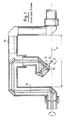
- (21) denotes a first axis of rotation and (22) a second axis of rotation, which together form the acute angle (27) and at the intersection of which the focus (14) of the lens (13) lies, so that its position is not changed by rotations about the axes of rotation (21, 22).
- the maximum inclination of the laser beam incident on the focus (14) to the axis of rotation (21) is twice the angle (27); this inclination can be adjusted for each azimuth angle due to the unobstructed rotatability about the axis (21).
- An advantage of the device according to the invention is that not only is the mechanical outlay considerably less and a plane mirror is required less than in the known device shown in FIG. 1, but the structure is also independent of the size of the workpiece to be machined.
- FIG. 3 shows another embodiment of the invention, in which the last plane mirror (28) from FIG. 2 is replaced by a paraboloid mirror (33), as a result of which the lens (13) from FIG. 2 is omitted.
Abstract
Description
Die vorliegende Erfindung betrifft eine Drehspiegelanordnung für einen Laserstrahl, die zwei Drehachsen und eine Fokussiereinrichtung enthält, wobei der Fokus der Fokussiereinrichtung im Schnittpunkt der Drehachsen liegt.The present invention relates to a rotating mirror arrangement for a laser beam, which contains two axes of rotation and a focusing device, the focus of the focusing device being at the intersection of the axes of rotation.
Bei der Materialbearbeitung mit Lasern an räumlichen Werkstücken sind im allgemeinen fünf Freiheitsgrade der Bewegung notwendig, und zwar drei zum Anfahren des Arbeitspunktes und zwei weitere zur Einstellung der Strahlrichtung, die meist senkrecht zur oft nicht ebenen Werkstückoberfläche erfolgt.When processing materials with lasers on three-dimensional workpieces, five degrees of freedom of movement are generally necessary, three for moving to the working point and two more for setting the beam direction, which is usually perpendicular to the often non-flat workpiece surface.
Vielfach sind Laseranlagen im Gebrauch, bei denen der Arbeitspunkt durch Linearbewegungen angefahren wird, entweder durch Führung des Laserstrahls mit linear bewegten Spiegeln in einem Portalsystem oder durch Bewegung des Werkstücks. Die Strahlrichtung wird mit Hilfe von Drehspiegeln eingestellt, wobei durch Drehungen um zwei Achsen jede Strahlrichtung eingestellt werden kann.Laser systems are often used in which the working point is approached by linear movements, either by guiding the laser beam with linearly moving mirrors in a portal system or by moving the workpiece. The beam direction is set with the help of rotating mirrors, whereby each beam direction can be set by rotating around two axes.
Derartige Anlagen haben einen wesentlichen Nachteil: eine Veränderung der Strahlrichtung bewirkt gleichzeitig eine Veränderung der Position des Laserfokus, die dann durch Nachstellen der Linearbewegungen kompensiert werden muß. Dadurch wird der Steueralgorithmus merklich komplizierter und die Positionierzeit länger. Ein noch wesentlicherer Nachteil zeigt sich jedoch bei einer Abschätzung der Genauigkeitsforderungen.Such systems have a major disadvantage: a change in the beam direction simultaneously causes a change in the position of the laser focus, which must then be compensated for by adjusting the linear movements. This makes the control algorithm noticeably more complicated and the positioning time longer. However, an even more significant disadvantage arises when estimating the accuracy requirements.
Während die Positionstoleranzen in der Praxis sehr eng sind (z.B. ±0.1 mm), muß die Strahlrichtung nur näherungsweise eingestellt werden (z.B. ±5o). Wenn aber die Richtung eine Rückwirkung auf die Position hat, dann muß die Winkeleinstellung allein wegen dieser Rückwirkung mit einer Toleranz von etwa ±1′ erfolgen, also rund zwei Größenordnungen genauer.While the position tolerances are very narrow in practice (e.g. ± 0.1 mm), the beam direction only has to be set approximately (e.g. ± 5 o ). If, however, the direction has an effect on the position, then the angle setting must have a tolerance of only because of this effect about ± 1 ', about two orders of magnitude more precisely.
Es ist daher zweckmäßig, eine Drehspiegelanordnung zu verwenden, bei der die Änderung der Strahlrichtung keinen Einfluß auf die Fokuslage hat. Eine bekannte Anlage (LBI-6A der Fa. Binder, beschrieben in einem 4seitigen Prospekt ohne nähere Kennzeichnung), welche diese Forderung erfüllt, ist schematisch in Figur 1 dargestellt. Dabei ist mit (11) eine erste Drehachse und mit (12) eine zweite Drehachse bezeichnet, um welche die Fokussiereinrichtung (13) gedreht werden kann. Der Fokus (14) des Laserstrahles (15) liegt im Schnittpunkt der Drehachsen (11, 12) und wandert daher bei Drehungen nicht aus.It is therefore expedient to use a rotating mirror arrangement in which the change in the beam direction has no influence on the focus position. A known system (LBI-6A from Binder, described in a 4-page brochure without further identification), which fulfills this requirement, is shown schematically in FIG. Here, (11) denotes a first axis of rotation and (12) a second axis of rotation, about which the focusing device (13) can be rotated. The focus (14) of the laser beam (15) lies at the intersection of the axes of rotation (11, 12) and therefore does not migrate during rotations.
Nachteilig an dieser bekannten Einrichtung ist, daß die Länge (L) des Bügels (16) so groß sein muß, daß das größte in Frage kommende Werkstück ausreichend bewegt werden kann. Die Einrichtung ist infolgedessen sehr aufwendig und entsprechend teuer.A disadvantage of this known device is that the length (L) of the bracket (16) must be so great that the largest workpiece in question can be moved sufficiently. As a result, the device is very complex and correspondingly expensive.
Der vorliegenden Erfindung liegt daher die Aufgabe zugrunde, eine Einrichtung zu schaffen, die trotz geringen Aufwandes auch für sehr große Werkstücke geeignet ist.The present invention is therefore based on the object of providing a device which, despite little effort, is also suitable for very large workpieces.
Die gestellte Aufgabe wird erfindungsgemäß dadurch gelöst, daß die Drehachsen in einem spitzen Winkel zueinander angeordnet sind.The object is achieved in that the axes of rotation are arranged at an acute angle to each other.
In einer vorteilhaften Ausführungsform beträgt der Winkel zwischen den Drehachsen 45o.In an advantageous embodiment, the angle between the axes of rotation is 45 ° .
Weitere vorteilhafte der Erfindung gehen aus den Unteransprüchen und den Erläuterungen zu den Figuren hervor.Further advantageous of the invention emerge from the subclaims and the explanations for the figures.
Die Erfindung wird im folgenden anhand der in den Figuren 2 und 3 dargestellten Ausführungsbeispielen näher erläutert. Dabei zeigen
- Fig. 2 eine Ausführungsform, bei der die Fokussierung mit einer Linse erfolgt und
- Fig. 3 eine Ausführungsform, bei der die Fokussierung mit einem Paraboloidspiegel erfolgt.
- Fig. 2 shows an embodiment in which the focusing takes place with a lens and
- Fig. 3 shows an embodiment in which the focusing takes place with a paraboloid mirror.
In Figur 2 ist mit (21) eine erste Drehachse und mit (22) eine zweite Drehachse bezeichnet, die miteinander den spitzen Winkel (27) bilden und in deren Schnittpunkt der Fokus (14) der Linse (13) liegt, so daß seine Lage durch Drehungen um die Drehachsen (21, 22) nicht verändert wird. Die maximale Neigung des auf den Fokus (14) auftreffenden Laserstrahles zur Drehachse (21) beträgt das Zweifache des Winkels (27); diese Neigung kann durch die ungehinderte Drehbarkeit um die Achse (21) für jeden Azimutwinkel eingestellt werden.In Figure 2, (21) denotes a first axis of rotation and (22) a second axis of rotation, which together form the acute angle (27) and at the intersection of which the focus (14) of the lens (13) lies, so that its position is not changed by rotations about the axes of rotation (21, 22). The maximum inclination of the laser beam incident on the focus (14) to the axis of rotation (21) is twice the angle (27); this inclination can be adjusted for each azimuth angle due to the unobstructed rotatability about the axis (21).
Mit (28) sind Planspiegel bezeichnet, deren Neigungen zu dem auftreffenden Laserstrahl (15) unverändert bleiben, d.h. außer den Drehbewegungen um die Drehachsen (21, 22) findet keine weitere Bewegung von optischen Elementen statt.With (28) plane mirrors are designated, the inclinations of the incident laser beam (15) remain unchanged, i.e. apart from the rotary movements around the axes of rotation (21, 22), no further movement of optical elements takes place.
Vorteilhaft an der erfindungsgemäßen Einrichtung ist, daß nicht nur der mechanische Aufwand erheblich geringer ist und ein Planspiegel weniger benötigt wird als bei der bekannten, in Figur 1 dargestellten Einrichtung, sondern daß der Aufbau auch von der Größe des zu bearbeitenden Werkstückes unabhängig ist.An advantage of the device according to the invention is that not only is the mechanical outlay considerably less and a plane mirror is required less than in the known device shown in FIG. 1, but the structure is also independent of the size of the workpiece to be machined.
In Figur 3 ist eine andere Ausführungsform der Erfindung dargestellt, bei welcher der letzte Planspiegel (28) von Figur 2 durch einen Paraboloidspiegel (33) ersetzt ist, wodurch die Linse (13) von Figur 2 entfällt.FIG. 3 shows another embodiment of the invention, in which the last plane mirror (28) from FIG. 2 is replaced by a paraboloid mirror (33), as a result of which the lens (13) from FIG. 2 is omitted.
Claims (4)
Applications Claiming Priority (2)
| Application Number | Priority Date | Filing Date | Title |
|---|---|---|---|
| DE3822292A DE3822292A1 (en) | 1988-07-01 | 1988-07-01 | TURN MIRROR ARRANGEMENT FOR A LASER BEAM |
| DE3822292 | 1988-07-01 |
Publications (2)
| Publication Number | Publication Date |
|---|---|
| EP0348796A2 true EP0348796A2 (en) | 1990-01-03 |
| EP0348796A3 EP0348796A3 (en) | 1990-03-28 |
Family
ID=6357755
Family Applications (1)
| Application Number | Title | Priority Date | Filing Date |
|---|---|---|---|
| EP89111197A Withdrawn EP0348796A3 (en) | 1988-07-01 | 1989-06-20 | Mirror rotating system for a laser beam |
Country Status (3)
| Country | Link |
|---|---|
| EP (1) | EP0348796A3 (en) |
| JP (1) | JPH0247623A (en) |
| DE (1) | DE3822292A1 (en) |
Cited By (1)
| Publication number | Priority date | Publication date | Assignee | Title |
|---|---|---|---|---|
| FR2717412A1 (en) * | 1994-03-18 | 1995-09-22 | Yswil Verwarmingstech Bv | Device for machining with a laser beam |
Citations (4)
| Publication number | Priority date | Publication date | Assignee | Title |
|---|---|---|---|---|
| US4673795A (en) * | 1984-10-15 | 1987-06-16 | General Electric Company | Integrated robotic laser material processing and imaging system |
| JPS6349389A (en) * | 1986-08-18 | 1988-03-02 | Nippei Toyama Corp | Laser beam machine |
| EP0266764A2 (en) * | 1986-11-07 | 1988-05-11 | Fried. Krupp Gesellschaft mit beschränkter Haftung | Seam-following method and means for a power laser beam |
| JPS63108982A (en) * | 1986-06-30 | 1988-05-13 | Nippei Toyama Corp | Nozzle for laser beam machine |
-
1988
- 1988-07-01 DE DE3822292A patent/DE3822292A1/en not_active Withdrawn
-
1989
- 1989-06-20 EP EP89111197A patent/EP0348796A3/en not_active Withdrawn
- 1989-06-30 JP JP1167170A patent/JPH0247623A/en active Pending
Patent Citations (4)
| Publication number | Priority date | Publication date | Assignee | Title |
|---|---|---|---|---|
| US4673795A (en) * | 1984-10-15 | 1987-06-16 | General Electric Company | Integrated robotic laser material processing and imaging system |
| JPS63108982A (en) * | 1986-06-30 | 1988-05-13 | Nippei Toyama Corp | Nozzle for laser beam machine |
| JPS6349389A (en) * | 1986-08-18 | 1988-03-02 | Nippei Toyama Corp | Laser beam machine |
| EP0266764A2 (en) * | 1986-11-07 | 1988-05-11 | Fried. Krupp Gesellschaft mit beschränkter Haftung | Seam-following method and means for a power laser beam |
Cited By (1)
| Publication number | Priority date | Publication date | Assignee | Title |
|---|---|---|---|---|
| FR2717412A1 (en) * | 1994-03-18 | 1995-09-22 | Yswil Verwarmingstech Bv | Device for machining with a laser beam |
Also Published As
| Publication number | Publication date |
|---|---|
| JPH0247623A (en) | 1990-02-16 |
| DE3822292A1 (en) | 1990-01-04 |
| EP0348796A3 (en) | 1990-03-28 |
Similar Documents
| Publication | Publication Date | Title |
|---|---|---|
| DE2637533C2 (en) | Positioning system for the slide of a microscope | |
| DE3145878C2 (en) | ||
| EP0659520A1 (en) | Machine-tool | |
| DE19525482A1 (en) | Robot arm for sliding and positioning object in plane - has carriages moved by electric motor over guide rail whereby carriages are connected together by joint elements with workpiece fixed at mid point of joints | |
| DE2657705C3 (en) | Device for further processing of a developed photographic film | |
| EP0516103A1 (en) | Lathe comprising at least one basic unit | |
| DE3136241C2 (en) | Use of a probe element and probe element that can be moved with the grinding wheel of an NC repetition-controlled projection shape grinding machine for this use | |
| EP1224055A1 (en) | Processing machine for moving a tool or workpiece in a multiaxial manner | |
| EP0084624A2 (en) | Length measuring device | |
| EP0348796A2 (en) | Mirror rotating system for a laser beam | |
| DE3400017C2 (en) | ||
| DE2113980C2 (en) | Device for aligning a workpiece | |
| EP1882960A2 (en) | Adjustable pin hole | |
| DE1777087B1 (en) | Gear cutting machine | |
| DE2326024C2 (en) | Device for cutting sheets, foils or the like | |
| EP0847548A1 (en) | Device for compensating guide tolerance in multi-axis positioners | |
| DE3734144A1 (en) | Laser-cutting head | |
| DE2360453A1 (en) | Adjustable diaphragm mount for laser apparatus - has diaphragm adjustment in three directions relative to fixed optical system | |
| DE2052502C3 (en) | Adjustment table | |
| DE1814201A1 (en) | Device for the mutual arrangement of two flat workpieces | |
| EP0217741A2 (en) | Holding facility for an imaging or objective frame for a compartment camera | |
| DE3446306A1 (en) | Process and apparatus for the surface machining of substrate plates for magnetic storage discs | |
| DE102004010535B4 (en) | Movement drive for use in e.g. ion processing equipment, has pendulum holding devices with axles that intersect at right angles, such that oscillating motion of torque motors, arranged outside vacuum container, is directly realized at axles | |
| DD242855A1 (en) | LEVEL GUIDE GEAR TO CHANGE THE POSITIONING ANGLE OF A WORKER AT A CONSTANT ENDING POINT | |
| DE2538523C2 (en) | Corpuscular transmission scanning microscope with an energy analyzer |
Legal Events
| Date | Code | Title | Description |
|---|---|---|---|
| PUAI | Public reference made under article 153(3) epc to a published international application that has entered the european phase |
Free format text: ORIGINAL CODE: 0009012 |
|
| AK | Designated contracting states |
Kind code of ref document: A2 Designated state(s): DE FR GB IT |
|
| PUAL | Search report despatched |
Free format text: ORIGINAL CODE: 0009013 |
|
| AK | Designated contracting states |
Kind code of ref document: A3 Designated state(s): DE FR GB IT |
|
| STAA | Information on the status of an ep patent application or granted ep patent |
Free format text: STATUS: THE APPLICATION IS DEEMED TO BE WITHDRAWN |
|
| 18D | Application deemed to be withdrawn |
Effective date: 19901001 |