EP0349210A2 - Electronic apparatus with a memory card storage device - Google Patents
Electronic apparatus with a memory card storage device Download PDFInfo
- Publication number
- EP0349210A2 EP0349210A2 EP89306373A EP89306373A EP0349210A2 EP 0349210 A2 EP0349210 A2 EP 0349210A2 EP 89306373 A EP89306373 A EP 89306373A EP 89306373 A EP89306373 A EP 89306373A EP 0349210 A2 EP0349210 A2 EP 0349210A2
- Authority
- EP
- European Patent Office
- Prior art keywords
- lid
- opening
- locking plate
- main casing
- memory card
- Prior art date
- Legal status (The legal status is an assumption and is not a legal conclusion. Google has not performed a legal analysis and makes no representation as to the accuracy of the status listed.)
- Granted
Links
- 238000007789 sealing Methods 0.000 claims description 2
- 239000000428 dust Substances 0.000 description 4
- 230000006835 compression Effects 0.000 description 3
- 238000007906 compression Methods 0.000 description 3
- 230000000694 effects Effects 0.000 description 2
- 238000000034 method Methods 0.000 description 2
- 230000002093 peripheral effect Effects 0.000 description 2
- 230000008569 process Effects 0.000 description 2
- 230000004308 accommodation Effects 0.000 description 1
- 230000009471 action Effects 0.000 description 1
- 230000008859 change Effects 0.000 description 1
- 238000010276 construction Methods 0.000 description 1
- 230000010365 information processing Effects 0.000 description 1
- 238000003780 insertion Methods 0.000 description 1
- 230000037431 insertion Effects 0.000 description 1
- 238000005259 measurement Methods 0.000 description 1
- 230000007246 mechanism Effects 0.000 description 1
- 238000012986 modification Methods 0.000 description 1
- 230000004048 modification Effects 0.000 description 1
- 238000012545 processing Methods 0.000 description 1
Images


Classifications
-
- H—ELECTRICITY
- H05—ELECTRIC TECHNIQUES NOT OTHERWISE PROVIDED FOR
- H05K—PRINTED CIRCUITS; CASINGS OR CONSTRUCTIONAL DETAILS OF ELECTRIC APPARATUS; MANUFACTURE OF ASSEMBLAGES OF ELECTRICAL COMPONENTS
- H05K5/00—Casings, cabinets or drawers for electric apparatus
- H05K5/02—Details
- H05K5/0256—Details of interchangeable modules or receptacles therefor, e.g. cartridge mechanisms
- H05K5/0286—Receptacles therefor, e.g. card slots, module sockets, card groundings
-
- G—PHYSICS
- G06—COMPUTING; CALCULATING OR COUNTING
- G06K—GRAPHICAL DATA READING; PRESENTATION OF DATA; RECORD CARRIERS; HANDLING RECORD CARRIERS
- G06K13/00—Conveying record carriers from one station to another, e.g. from stack to punching mechanism
- G06K13/02—Conveying record carriers from one station to another, e.g. from stack to punching mechanism the record carrier having longitudinal dimension comparable with transverse dimension, e.g. punched card
- G06K13/08—Feeding or discharging cards
Definitions
- the present invention relates to electronic apparatus including a memory card storage device such as data collectors attached to electronic field or outdoor survey apparatus for use in surveying or measuring distances or gradients as are used in the civil engineering, architectural and constructional fields.
- the invention is concerned with that type of electronic apparatus which includes a main casing and a memory card storage device for receiving a memory card.
- Such electronic survey apparatus includes a data collector in order to reduce the time required for data processing and the entire surveying operation.
- the data collector is typically adapted to process the input information in a predetermined manner and store the result in the data collector and to display guidance messages to facilitate the input of information.
- a memory card be used as an external memory and that various programs be memorised in the memory card.
- Portable electronic calculators and translators and the like have adopted memory cards which are used after having been partly inserted into the portable electronic device.
- Portable calculators are generally used inside a building so that no special countermeasures are required to dustproof or waterproof the mechanism in which the memory card is inserted and stored. Thus, even if a part of the card is exposed, i.e. extends out of the body of the calculator or the like, no problems arise.
- the apparatus is of the type which may be used outside, e.g. a data collector, strong winds, rain and dust must be contended with and in order to ensure reliability of the apparatus some form of dustproofing is desirable.
- an electronic apparatus which includes a memory card storage device in which the memory card is inherently protected from dust, rain and the like and from accidental damage but can nevertheless be readily inserted in the apparatus and removed again.
- an electronic apparatus of the type referred to above is characterised in that the main casing includes a lid which is pivotally connected thereto, i.e. so as to be movable to an open and a closed position, and defines a space which accommodates a movable card connector and, in use, a memory card connected to the card connector, that one or more pivotal links are provided which are connected to the lid and pivotally connected to the main casing and that the card connector is connected to move with the or each pivotal link.
- the memory card is accommodated within the main casing and the lid is kept closed thereby protecting it from damage, dust and the like.
- the pivotal links rotate and due to the connection with the card connector the latter and thus also the memory card are moved forwardly so as to expose it from easy removal.
- connection between the card connector and the pivotal links may take various forms but it is preferred that the card connector is connected to at least one slide link, the or each slide link being connected to an associated pivotal link by a pin which extends through an opening in the slide link and an elongate opening in a portion of the lid.
- the elongate opening preferably forms part of an L-shaped opening of which a portion extends transverse to the elongate portion and the opening in the slide link is preferably elongate and corresponds to the transverse portion.
- the apparatus includes a spring which acts on the lid in the opening direction and locking means arranged to lock the lid in the closed position.
- the locking means may take various forms but in one embodiment a locking plate is provided which is slidably attached to the main casing to move between a locked position and an unlocked position, the locking plate and the lid having cooperating means which engage to prevent opening of the lid when the locking plate is in the locked position and which permit opening of the lid when the locking plate is in the unlocked position.
- the cooperating means may also take various forms but preferably comprise one or more projections on the locking plate which engage in one or more notches or undercuts formed in a portion of the lid when the latter is in the closed position.
- the apparatus preferably includes a locking knob carried by the main casing which is operative to move the locking plate between the locked and unlocked positions.
- the locking knob is preferably rotatably connected to the main casing and carries an eccentric pin which is received in a slot in the locking plate whereby rotation of the locking knob results in linear movement of the locking plate.
- the latter protection may be increased by the provision of a sealing strip which extends around the opening in the main casing and forms a seal with the lid when it is closed.
- Figure 1 shows a data collector 1 including an input portion 2, a display portion 3 and a connector 4 used to connect the data collector 1 to another information processing device (not shown).
- a memory card storage device 5 in accordance with the present invention, as shown in Figure 2.
- the storage device includes a lid 8 functioning both as part of the rear wall 6 and as a holder for a memory card 7.
- the lid 8 is rotatably joined to the rear wall 6 by means of a hinge 9 of a channel shape.
- the lid 8 has a peripheral edge 10 adapted to contact a seal, which will be described below and a case portion 13 within the outer profile of the data collector and containing or receiving the memory card 7.
- the lid 8 also has a card connector 11 at about its centre.
- the card connector 11 is slidably fitted to the case portion 13 by a pair of slide links 14 which are attached on both sides of the card connector 11.
- the case portion 13 has a rectangular window 15 formed near its hinge side. Extending from the card connector 11 towards the interior of the data collector is a set of connector pins 16. The window 15 prevents the connector pins 16 from interferring with or contacting the case portion 13 when the card connector 11 slides.
- the rear wall 6 has an opening 17 which receives the lid 8 and has a seal groove 18 extending around its periphery.
- a seal 19 is provided in the seal groove 18 and is firmly contacted by the peripheral edge 10 of the lid.
- a bag portion 20, that is to say a web integral with the rear wall 6, is provided within the opening 17 at the end opposite to the hinged end which extends parallel and adjacent to the lid when it is closed.
- a pair of shaft supporters or lugs 21 extend from the outer face of the bag portion 20.
- One or more elongate pivotal links 23 are pivotally connected at one end to each lug 21 by a respective pin 22 and carry a laterally projecting slide pin 24 at their other end. The slide pins 24 engage in oval openings 25 in the slide links 14.
- the long axis of the oval openings is directed at right angles to the sliding direction of the slide links 14.
- the slide pins 24 have portions extending through the oval openings 25 and these portions slidably engage in L-shaped openings 27 which comprise a longitudinal portion and a short upwardly extending portion 43 and are formed in a pair of side walls 26 of the case portion 13.
- Each side wall 26 has a front and rear notch 30 which are adapted to engage with engagement portions 29 of a locking plate 28.
- Each notch 30 consists of an entry portion 31 through which the associated engagement portion 29 can enter and an undercut portion 32 with a tapered edge with which the engagement portion 29 engages.
- the locking plate 28 is U-shaped and embraces the edge of the opening 17, as shown in Figure 3.
- the engagement portions 29 are formed on the inside of the two limbs 33 of the locking plate 28 and extend inwardly.
- the upper edge of the engagement portions 29 is chamfered so as to smoothly engage the associated notch 30.
- the base 34 connecting the limbs 33 has a slit 35 extending longitudinally of the cross-portion 34.
- the locking plate 28 is placed on a stepped portion or shoulder 36 in which the seal groove 18 is formed and held slidably by locking plate clips 37.
- a locking knob 38 is rotatably secured to the rear wall 6 at the end opposite part to the hinge of the storage device 5.
- An eccentric pin 39 on the locking knob 38 extends into the slit 35.
- a compression spring 40 acts on the lid 8 in the direction of its length and tends to open it.
- a connector 41 Connected to the body of the data collector 1 is a connector 41.
- a pad or cushion 42 secured to the inner surface of the web 20 restrains rattling or vibration of the memory card 7 when it is inserted into the storage device.
- the operation of the data collector 1 with the memory card storage device 5 is as follows:
- FIGs 3,4,5 and 7 show the data collector 1 with the card storage device 5 and the memory card 7 stored in it.
- the engagement portions 29 of the locking plate 28 engage in the portions 32 of the notches 30 and the lid 8 is locked in its closed position.
- the locking knob 38 is rotated through 180 o . Due to the eccentric position of the pin 39 it moves towards the hinge side of the card connector 11 by a distance which is twice the eccentricity. This movement of the pin 39 makes the locking plate 28 slide towards the hinge. When the locking plate 28 slides and the engagement portions 29 move into registry with the entrance portions 31 of the notches 30, the lid 8 is unlocked and the lid 8 opens a little under the action of the compression spring 40.
- the user can then easily remove the memory card 7 from the data collector 1.
- the slide pins 24 engage in the vertical portions 43 of the L-shaped openings 27, as described above, and the lid 8 is open as shown in Figure 8, sliding movement of the slide pins 24 is restrained. As a result, the lid 8 is locked firmly in position during insertion or removal of the memory card 7.
- the lid 8 When the card connector 11 is to be retracted, the lid 8 is closed after disengaging the slide pins 24 from the portions 43 and thereafter sliding them back along the openings 27. The lid 8 is finally closed by applying a light manual force to it and rotating the locking knob 38.
- the locking process is facilitated by engagement of the chamfered engagement portions 29 and the tapered faces of the undercuts 32.
- the wedging effect of the wedge-shaped engagement portions 29 in the undercuts 32 deforms the seal 19 enabling the lid 8 to lock firmly and produce an effective seal.
- the lid 8 is locked by means of an eccentric pin and cooperating locking plate.
- a knurled screw may be used to obtain the same effect.
- the compression spring for urging the lid 8 in the opening direction may be replaced by e.g. a torsion spring adapted to rotate the pivotal links anti-clockwise.
- a leaf spring 45 may be secured to the outer face of the web 20 to apply an opening force to the lid 8. If the slide links 14 are pivotally connected to the card connector 11 and the pivotal links 23, then the portions 43 of the openings 27 may be omitted.
Abstract
Description
- The present invention relates to electronic apparatus including a memory card storage device such as data collectors attached to electronic field or outdoor survey apparatus for use in surveying or measuring distances or gradients as are used in the civil engineering, architectural and constructional fields. The invention is concerned with that type of electronic apparatus which includes a main casing and a memory card storage device for receiving a memory card.
- Nowadays, much of the survey apparatus used in the civil engineering and architectural fields is of electronic type so as to increase the precision of the measurements and to save time. Such electronic survey apparatus includes a data collector in order to reduce the time required for data processing and the entire surveying operation.
- The data collector is typically adapted to process the input information in a predetermined manner and store the result in the data collector and to display guidance messages to facilitate the input of information.
- It is necessary to have a large memory for storing the various programs which are required. However, it is also necessary that the data collector is small and readily portable and it is thus difficult to accommodate the various programs. If the collector is provided with a sufficient storage space for these programs, it becomes unacceptably expensive.
- It has therefore been proposed that a memory card be used as an external memory and that various programs be memorised in the memory card. Portable electronic calculators and translators and the like have adopted memory cards which are used after having been partly inserted into the portable electronic device.
- Portable calculators are generally used inside a building so that no special countermeasures are required to dustproof or waterproof the mechanism in which the memory card is inserted and stored. Thus, even if a part of the card is exposed, i.e. extends out of the body of the calculator or the like, no problems arise.
- However, if the apparatus is of the type which may be used outside, e.g. a data collector, strong winds, rain and dust must be contended with and in order to ensure reliability of the apparatus some form of dustproofing is desirable.
- Furthermore, if a part of the memory card is exposed it is potentially subject to accidental damage.
- Accordingly, it is the object of the present invention to provide an electronic apparatus which includes a memory card storage device in which the memory card is inherently protected from dust, rain and the like and from accidental damage but can nevertheless be readily inserted in the apparatus and removed again.
- According to the present invention an electronic apparatus of the type referred to above is characterised in that the main casing includes a lid which is pivotally connected thereto, i.e. so as to be movable to an open and a closed position, and defines a space which accommodates a movable card connector and, in use, a memory card connected to the card connector, that one or more pivotal links are provided which are connected to the lid and pivotally connected to the main casing and that the card connector is connected to move with the or each pivotal link. Thus, in use, the memory card is accommodated within the main casing and the lid is kept closed thereby protecting it from damage, dust and the like. However, when the lid is open the pivotal links rotate and due to the connection with the card connector the latter and thus also the memory card are moved forwardly so as to expose it from easy removal.
- The connection between the card connector and the pivotal links may take various forms but it is preferred that the card connector is connected to at least one slide link, the or each slide link being connected to an associated pivotal link by a pin which extends through an opening in the slide link and an elongate opening in a portion of the lid. The elongate opening preferably forms part of an L-shaped opening of which a portion extends transverse to the elongate portion and the opening in the slide link is preferably elongate and corresponds to the transverse portion. The provision of one or more L-shaped openings results in the lid inherently being locked when in the open position and the provision of the elongate opening in the slide link permits the pin to move in the transverse portion of the L-shaped opening without resulting in simultaneous movement of the slide link.
- It is preferred that the apparatus includes a spring which acts on the lid in the opening direction and locking means arranged to lock the lid in the closed position. The locking means may take various forms but in one embodiment a locking plate is provided which is slidably attached to the main casing to move between a locked position and an unlocked position, the locking plate and the lid having cooperating means which engage to prevent opening of the lid when the locking plate is in the locked position and which permit opening of the lid when the locking plate is in the unlocked position. The cooperating means may also take various forms but preferably comprise one or more projections on the locking plate which engage in one or more notches or undercuts formed in a portion of the lid when the latter is in the closed position.
- The apparatus preferably includes a locking knob carried by the main casing which is operative to move the locking plate between the locked and unlocked positions. The locking knob is preferably rotatably connected to the main casing and carries an eccentric pin which is received in a slot in the locking plate whereby rotation of the locking knob results in linear movement of the locking plate.
- Whilst the accommodation of the memory card in a space which is closed by the lid protects the memory card from accidental mechanical damage and, in most cases, from damage by dust or the like, the latter protection may be increased by the provision of a sealing strip which extends around the opening in the main casing and forms a seal with the lid when it is closed.
- Further features and details of the invention will be apparent from the following description of two specific embodiments which is given by way of example with reference to the accompanying drawings, in which:
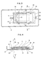
- Figure 1 is a perspective view from above of one embodiment of data collector incorporating a memory card storage device in accordance with the present invention;
- Figure 2 is a perspective view from below of the data collector showing the memory card storage device pivoted outwardly;
- Figure 3 is a crooss-sectional view in the direction of the arrows A-A in Figure 1;
- Figure 4 is a sectional view on the line B-B in Figure 3;
- Figure 5 is a sectional view on the line C-C in Figure 4;
- Figure 6 is a view similar to Figure 5 showing the lid of the data collector open;
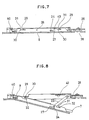
- Figure 7 is a sectional view taken on the line D-D in Figure 4 with the lid closed;
- Figure 8 shows the data collector with the lid open;
- Figure 9 is a perspective view showing the relationship of the lid to the locking plate; and
- Figure 10 is a view similar to Figure 8 of a modified construction of memory card storage device.
- Figure 1 shows a
data collector 1 including aninput portion 2, adisplay portion 3 and a connector 4 used to connect thedata collector 1 to another information processing device (not shown). - Provided at the rear 6 of the
data collector 1 is a memorycard storage device 5 in accordance with the present invention, as shown in Figure 2. - The structure of the
storage device 5 will be described with reference to Figures 3 to 9. - The storage device includes a
lid 8 functioning both as part of therear wall 6 and as a holder for amemory card 7. Thelid 8 is rotatably joined to therear wall 6 by means of ahinge 9 of a channel shape. Thelid 8 has aperipheral edge 10 adapted to contact a seal, which will be described below and acase portion 13 within the outer profile of the data collector and containing or receiving thememory card 7. Thelid 8 also has acard connector 11 at about its centre. Thecard connector 11 is slidably fitted to thecase portion 13 by a pair ofslide links 14 which are attached on both sides of thecard connector 11. - The
case portion 13 has arectangular window 15 formed near its hinge side. Extending from thecard connector 11 towards the interior of the data collector is a set ofconnector pins 16. Thewindow 15 prevents theconnector pins 16 from interferring with or contacting thecase portion 13 when thecard connector 11 slides. - The
rear wall 6 has anopening 17 which receives thelid 8 and has aseal groove 18 extending around its periphery. Aseal 19 is provided in theseal groove 18 and is firmly contacted by theperipheral edge 10 of the lid. Abag portion 20, that is to say a web integral with therear wall 6, is provided within theopening 17 at the end opposite to the hinged end which extends parallel and adjacent to the lid when it is closed. A pair of shaft supporters orlugs 21 extend from the outer face of thebag portion 20. One or more elongatepivotal links 23 are pivotally connected at one end to eachlug 21 by arespective pin 22 and carry a laterally projectingslide pin 24 at their other end. Theslide pins 24 engage inoval openings 25 in theslide links 14. The long axis of the oval openings is directed at right angles to the sliding direction of theslide links 14. Theslide pins 24 have portions extending through theoval openings 25 and these portions slidably engage in L-shaped openings 27 which comprise a longitudinal portion and a short upwardly extendingportion 43 and are formed in a pair ofside walls 26 of thecase portion 13. Eachside wall 26 has a front andrear notch 30 which are adapted to engage withengagement portions 29 of alocking plate 28. Eachnotch 30 consists of anentry portion 31 through which the associatedengagement portion 29 can enter and anundercut portion 32 with a tapered edge with which theengagement portion 29 engages. - The
locking plate 28 is U-shaped and embraces the edge of theopening 17, as shown in Figure 3. Theengagement portions 29 are formed on the inside of the twolimbs 33 of thelocking plate 28 and extend inwardly. The upper edge of theengagement portions 29 is chamfered so as to smoothly engage the associatednotch 30. Thebase 34 connecting thelimbs 33 has aslit 35 extending longitudinally of thecross-portion 34. Thelocking plate 28 is placed on a stepped portion orshoulder 36 in which theseal groove 18 is formed and held slidably bylocking plate clips 37. - A
locking knob 38 is rotatably secured to therear wall 6 at the end opposite part to the hinge of thestorage device 5. Aneccentric pin 39 on the lockingknob 38 extends into theslit 35. - As shown in Figure 3, a
compression spring 40 acts on thelid 8 in the direction of its length and tends to open it. Connected to the body of thedata collector 1 is aconnector 41. - A pad or cushion 42 secured to the inner surface of the
web 20 restrains rattling or vibration of thememory card 7 when it is inserted into the storage device. - The operation of the
data collector 1 with the memorycard storage device 5 is as follows: - Figures 3,4,5 and 7 show the
data collector 1 with thecard storage device 5 and thememory card 7 stored in it. In the stored condition, theengagement portions 29 of the lockingplate 28 engage in theportions 32 of thenotches 30 and thelid 8 is locked in its closed position. - In order to remove the
memory card 7, the lockingknob 38 is rotated through 180o. Due to the eccentric position of thepin 39 it moves towards the hinge side of thecard connector 11 by a distance which is twice the eccentricity. This movement of thepin 39 makes the lockingplate 28 slide towards the hinge. When the lockingplate 28 slides and theengagement portions 29 move into registry with theentrance portions 31 of thenotches 30, thelid 8 is unlocked and thelid 8 opens a little under the action of thecompression spring 40. When a manual force is applied to thelid 8 in order to open it further, thelid 8 rotates clockwise, as shown in Figures 6 and 8, thepivotal links 23 rotate anti-clockwise, the slide pins 24 move in the L-shapedopenings 27 towards the end of thelid 8 and the slide links 14, connected to thepivotal links 23 by means of the slide pins 24, slide toward the open end of thelid 8 together with thecard connector 11. When the slide pins 24 reach the end of their travel, they enter thevertical portions 43 of the L-shapedopenings 27. This change in direction of the movement of the slide pins 24 is permitted by theoval openings 25 in the slide links 14. This position is the final open position of thelid 8, in which the sliding movement of thecard connector 11 causes the front edge of thememory card 7 to extend a little beyond the front end of thelid 8. - The user can then easily remove the
memory card 7 from thedata collector 1. When the slide pins 24 engage in thevertical portions 43 of the L-shapedopenings 27, as described above, and thelid 8 is open as shown in Figure 8, sliding movement of the slide pins 24 is restrained. As a result, thelid 8 is locked firmly in position during insertion or removal of thememory card 7. - When the
card connector 11 is to be retracted, thelid 8 is closed after disengaging the slide pins 24 from theportions 43 and thereafter sliding them back along theopenings 27. Thelid 8 is finally closed by applying a light manual force to it and rotating the lockingknob 38. - Due to the resultant movement of the
eccentric pin 39, as described above, the lockingplate 28 is moved towards the front end of thelid 8 and theengagement portions 29 engage in theundercuts 32 thereby locking thelid 8. - The locking process is facilitated by engagement of the chamfered
engagement portions 29 and the tapered faces of theundercuts 32. In addition, the wedging effect of the wedge-shapedengagement portions 29 in theundercuts 32 deforms theseal 19 enabling thelid 8 to lock firmly and produce an effective seal. - In the embodiment described above, the
lid 8 is locked by means of an eccentric pin and cooperating locking plate. However, a knurled screw may be used to obtain the same effect. Also the compression spring for urging thelid 8 in the opening direction may be replaced by e.g. a torsion spring adapted to rotate the pivotal links anti-clockwise. - Alternatively, as shown in Figure 10, a leaf spring 45 may be secured to the outer face of the
web 20 to apply an opening force to thelid 8. If the slide links 14 are pivotally connected to thecard connector 11 and thepivotal links 23, then theportions 43 of theopenings 27 may be omitted. - Although only two embodiments of the invention have been described, it will be apparent that other embodiments and modifications of the invention are possible. The present invention can of course be applied to electric and electronic devices other than the data collector described above.
Claims (9)
Applications Claiming Priority (2)
| Application Number | Priority Date | Filing Date | Title |
|---|---|---|---|
| JP63162475A JP2628346B2 (en) | 1988-07-01 | 1988-07-01 | Memory card storage |
| JP162475/88 | 1988-07-01 |
Publications (3)
| Publication Number | Publication Date |
|---|---|
| EP0349210A2 true EP0349210A2 (en) | 1990-01-03 |
| EP0349210A3 EP0349210A3 (en) | 1990-03-07 |
| EP0349210B1 EP0349210B1 (en) | 1993-03-17 |
Family
ID=15755329
Family Applications (1)
| Application Number | Title | Priority Date | Filing Date |
|---|---|---|---|
| EP89306373A Expired - Lifetime EP0349210B1 (en) | 1988-07-01 | 1989-06-23 | Electronic apparatus with a memory card storage device |
Country Status (4)
| Country | Link |
|---|---|
| US (1) | US4986618A (en) |
| EP (1) | EP0349210B1 (en) |
| JP (1) | JP2628346B2 (en) |
| DE (1) | DE68905390T2 (en) |
Cited By (10)
| Publication number | Priority date | Publication date | Assignee | Title |
|---|---|---|---|---|
| GB2250846A (en) * | 1990-12-13 | 1992-06-17 | Technophone Ltd | Card reader |
| EP0656600A2 (en) * | 1993-11-09 | 1995-06-07 | Fujitsu Limited | An information processing system using portable terminal unit and data communication adapter therefor |
| EP0663649A1 (en) * | 1994-01-13 | 1995-07-19 | The Whitaker Corporation | PCMCIA connection device |
| EP0782089A2 (en) * | 1995-12-28 | 1997-07-02 | Hirose Electric Co., Ltd. | Surface contact card connector |
| US5939960A (en) * | 1996-07-10 | 1999-08-17 | Valeo Equipements Electriques Moteur | Motor vehicle starter having improved means for the electrical connection of the contactor |
| US5960208A (en) * | 1993-11-09 | 1999-09-28 | Fujitsu Limited | Data communication adapter for selectively supplying power to a communication control circuit or a portable terminal unit |
| GB2338811A (en) * | 1998-06-26 | 1999-12-29 | Nokia Mobile Phones Ltd | Cardholder |
| EP1729245A2 (en) | 2005-06-02 | 2006-12-06 | LG Electronics Inc. | Card ejecting mechanism and mobile communication terminal having the same |
| EP1906337A2 (en) | 2006-09-27 | 2008-04-02 | Bixolon Co., Ltd. | Information receiving apparatus |
| WO2012054567A3 (en) * | 2010-10-22 | 2012-06-28 | Xplore Technologies Corp. | Computer cartridge |
Families Citing this family (25)
| Publication number | Priority date | Publication date | Assignee | Title |
|---|---|---|---|---|
| KR0123926B1 (en) * | 1991-06-18 | 1997-11-26 | 야마지 게이조 | Video camera |
| JPH07234921A (en) * | 1993-12-28 | 1995-09-05 | Nikon Corp | Loading/unloading mechanism for recording medium |
| KR100368507B1 (en) * | 1994-03-09 | 2003-04-08 | 코닌클리케 필립스 일렉트로닉스 엔.브이. | Information exchange devices with electronic memory cards and radios for vehicles equipped with such devices |
| JPH08221525A (en) * | 1995-02-14 | 1996-08-30 | Nikon Corp | Device for loading recording medium |
| KR970038807A (en) * | 1995-12-28 | 1997-07-24 | 배순훈 | Front panel pivot structure |
| JPH09315061A (en) * | 1996-06-03 | 1997-12-09 | Minolta Co Ltd | Ic card and ic card-mounting apparatus |
| EP0833268A3 (en) * | 1996-09-20 | 1999-01-20 | Siemens Aktiengesellschaft | Card reading device |
| US20040157612A1 (en) * | 1997-04-25 | 2004-08-12 | Minerva Industries, Inc. | Mobile communication and stethoscope system |
| US7321783B2 (en) * | 1997-04-25 | 2008-01-22 | Minerva Industries, Inc. | Mobile entertainment and communication device |
| JP3033729B2 (en) * | 1998-02-16 | 2000-04-17 | 米沢日本電気株式会社 | Notebook PC with transformation function |
| US6493033B1 (en) | 1998-12-09 | 2002-12-10 | Eastman Kodak Company | Electronic apparatus adapted to receive a memory card |
| WO2002000240A2 (en) * | 2000-06-27 | 2002-01-03 | Qualilife Pharmaceuticals Inc. | Compositions and methods for treating females sexual response |
| JP2002288593A (en) * | 2001-03-23 | 2002-10-04 | Pioneer Electronic Corp | Electronic apparatus |
| JP2002351570A (en) * | 2001-05-29 | 2002-12-06 | Matsushita Electric Ind Co Ltd | Information terminal |
| JP2003203710A (en) * | 2002-01-09 | 2003-07-18 | Sony Corp | Waterproof-specification modular jack |
| JP2003317457A (en) * | 2002-04-26 | 2003-11-07 | Pioneer Electronic Corp | Electronic equipment, method for controlling power supply of electronic equipment, and method for driving front panel of electronic equipment |
| US8209267B2 (en) * | 2004-12-08 | 2012-06-26 | Lockheed Martin Corporation | Automatic revenue protection and adjustment of postal indicia products |
| US7431408B2 (en) * | 2006-03-15 | 2008-10-07 | In Win Development, Inc. | Movable cover-plate of a computer host |
| CN102083290B (en) * | 2009-11-30 | 2014-05-07 | 鸿富锦精密工业(深圳)有限公司 | Fixing mechanism |
| TWI426184B (en) * | 2010-01-11 | 2014-02-11 | Hon Hai Prec Ind Co Ltd | Fixing mechanism |
| CN102201251B (en) * | 2010-03-26 | 2015-03-25 | 鸿富锦精密工业(深圳)有限公司 | Storage apparatus connection structure and composite connector thereof |
| CN102201252B (en) * | 2010-03-26 | 2014-04-30 | 鸿富锦精密工业(深圳)有限公司 | Connection structure of storage device |
| CN102340078B (en) * | 2010-07-24 | 2013-10-02 | 富士康(昆山)电脑接插件有限公司 | Connector |
| CN103887650A (en) * | 2012-12-20 | 2014-06-25 | 深圳富泰宏精密工业有限公司 | Chip holding structure and electronic device having chip holding structure |
| TWI658354B (en) * | 2017-12-21 | 2019-05-01 | 廣積科技股份有限公司 | Mobile computer-based host |
Citations (2)
| Publication number | Priority date | Publication date | Assignee | Title |
|---|---|---|---|---|
| DE3313802A1 (en) * | 1982-04-15 | 1983-10-27 | Ricoh Co., Ltd., Tokyo | CONTAINER FOR A STORAGE CASSETTE |
| JPS6095782A (en) * | 1983-10-29 | 1985-05-29 | Nippon Telegr & Teleph Corp <Ntt> | Signal transmission device of memory card write and read device |
Family Cites Families (8)
| Publication number | Priority date | Publication date | Assignee | Title |
|---|---|---|---|---|
| US2187320A (en) * | 1938-10-19 | 1940-01-16 | Carl H Hoffstetter | Stove or range |
| US2363149A (en) * | 1941-09-26 | 1944-11-21 | Rousso Jacques | Towel cabinet |
| US2570054A (en) * | 1948-09-15 | 1951-10-02 | Clair C Gardner | Magazine cabinet having tiltable receptacles |
| US2690945A (en) * | 1950-12-09 | 1954-10-05 | Ritter Co Inc | Medical equipment stand |
| US2775230A (en) * | 1954-12-01 | 1956-12-25 | Burnie J Craig | Pen desk set |
| US2786730A (en) * | 1955-09-20 | 1957-03-26 | Philco Corp | Cabinet equipment |
| US2849270A (en) * | 1956-08-09 | 1958-08-26 | Aln D Warnock | Cabinet with upfolding door |
| US4368937A (en) * | 1981-02-17 | 1983-01-18 | The Boeing Company | Overhead stowage bin mechanism |
-
1988
- 1988-07-01 JP JP63162475A patent/JP2628346B2/en not_active Expired - Lifetime
-
1989
- 1989-06-08 US US07/363,096 patent/US4986618A/en not_active Expired - Lifetime
- 1989-06-23 EP EP89306373A patent/EP0349210B1/en not_active Expired - Lifetime
- 1989-06-23 DE DE8989306373T patent/DE68905390T2/en not_active Expired - Fee Related
Patent Citations (2)
| Publication number | Priority date | Publication date | Assignee | Title |
|---|---|---|---|---|
| DE3313802A1 (en) * | 1982-04-15 | 1983-10-27 | Ricoh Co., Ltd., Tokyo | CONTAINER FOR A STORAGE CASSETTE |
| JPS6095782A (en) * | 1983-10-29 | 1985-05-29 | Nippon Telegr & Teleph Corp <Ntt> | Signal transmission device of memory card write and read device |
Non-Patent Citations (1)
| Title |
|---|
| PATENT ABSTRACTS OF JAPAN vol. 9, no. 243 (P-392)(1966) 30 September 1985, & JP-A-60 095 782 (NIPPON DENSHIN DENWA KOSHA) 29 May 1985, * |
Cited By (26)
| Publication number | Priority date | Publication date | Assignee | Title |
|---|---|---|---|---|
| GB2250846A (en) * | 1990-12-13 | 1992-06-17 | Technophone Ltd | Card reader |
| GB2250846B (en) * | 1990-12-13 | 1994-08-24 | Technophone Ltd | Card reader |
| US6163268A (en) * | 1993-11-09 | 2000-12-19 | Fujitsu Limited | Information processing system using portable terminal unit and data communication adapter therefor |
| US5960208A (en) * | 1993-11-09 | 1999-09-28 | Fujitsu Limited | Data communication adapter for selectively supplying power to a communication control circuit or a portable terminal unit |
| EP0656600A2 (en) * | 1993-11-09 | 1995-06-07 | Fujitsu Limited | An information processing system using portable terminal unit and data communication adapter therefor |
| US5983290A (en) * | 1993-11-09 | 1999-11-09 | Fujitsu Limited | Information processing system using portable terminal unit and data communication adapter therefor |
| EP0656600A3 (en) * | 1993-11-09 | 1998-04-01 | Fujitsu Limited | An information processing system using portable terminal unit and data communication adapter therefor |
| EP0663649A1 (en) * | 1994-01-13 | 1995-07-19 | The Whitaker Corporation | PCMCIA connection device |
| US5637001A (en) * | 1994-01-13 | 1997-06-10 | The Whitaker Corporation | PCMCIA connection device |
| EP0782089A3 (en) * | 1995-12-28 | 1999-07-14 | Hirose Electric Co., Ltd. | Surface contact card connector |
| EP0782089A2 (en) * | 1995-12-28 | 1997-07-02 | Hirose Electric Co., Ltd. | Surface contact card connector |
| US5939960A (en) * | 1996-07-10 | 1999-08-17 | Valeo Equipements Electriques Moteur | Motor vehicle starter having improved means for the electrical connection of the contactor |
| GB2338811A (en) * | 1998-06-26 | 1999-12-29 | Nokia Mobile Phones Ltd | Cardholder |
| US6343945B1 (en) | 1998-06-26 | 2002-02-05 | Nokia Mobile Phones Ltd. | Cardholder cover and ejector |
| GB2338811B (en) * | 1998-06-26 | 2002-10-02 | Nokia Mobile Phones Ltd | A cardholder |
| US7494353B2 (en) | 2005-06-02 | 2009-02-24 | Lg Electronics Inc. | Card ejecting mechanism and mobile communication terminal having the same |
| EP1729245A2 (en) | 2005-06-02 | 2006-12-06 | LG Electronics Inc. | Card ejecting mechanism and mobile communication terminal having the same |
| EP1729245A3 (en) * | 2005-06-02 | 2008-07-23 | LG Electronics Inc. | Card ejecting mechanism and mobile communication terminal having the same |
| EP1906337A3 (en) * | 2006-09-27 | 2008-09-17 | Bixolon Co., Ltd. | Information receiving apparatus |
| EP1906337A2 (en) | 2006-09-27 | 2008-04-02 | Bixolon Co., Ltd. | Information receiving apparatus |
| US7766234B2 (en) | 2006-09-27 | 2010-08-03 | Bixolon Co., Ltd. | Information receiving apparatus |
| WO2012054567A3 (en) * | 2010-10-22 | 2012-06-28 | Xplore Technologies Corp. | Computer cartridge |
| US8373980B2 (en) | 2010-10-22 | 2013-02-12 | Explore Technologies Corp. | System for mounting a display to a computer |
| US8699220B2 (en) | 2010-10-22 | 2014-04-15 | Xplore Technologies Corp. | Computer with removable cartridge |
| US8699216B2 (en) | 2010-10-22 | 2014-04-15 | Xplore Technologies Corp. | Computer with door-mounted electronics |
| US8941981B2 (en) | 2010-10-22 | 2015-01-27 | Xplore Technologies Corp. | Computer with high intensity screen |
Also Published As
| Publication number | Publication date |
|---|---|
| DE68905390T2 (en) | 1993-06-24 |
| US4986618A (en) | 1991-01-22 |
| DE68905390D1 (en) | 1993-04-22 |
| JP2628346B2 (en) | 1997-07-09 |
| EP0349210B1 (en) | 1993-03-17 |
| EP0349210A3 (en) | 1990-03-07 |
| JPH0214393A (en) | 1990-01-18 |
Similar Documents
| Publication | Publication Date | Title |
|---|---|---|
| EP0349210B1 (en) | Electronic apparatus with a memory card storage device | |
| EP0525368B1 (en) | Electronic apparatus equipped with detachable unit | |
| EP0592090B1 (en) | Security mechanism for portable computer | |
| US4843223A (en) | Information processing device for IC card | |
| DE4138342C2 (en) | Device for accepting and holding a memory card | |
| DE60036153T2 (en) | Intermediate socket for card | |
| KR860000611B1 (en) | Cassette tape | |
| US5007859A (en) | Battery-containing apparatus | |
| EP0793188A2 (en) | Portable card reader-writer | |
| US5130892A (en) | Portable electronic device with battery pack retained by a spring-loaded slider unit | |
| JPS6242353B2 (en) | ||
| US6159632A (en) | Battery accommodating structure for electronic equipment | |
| EP0494503A1 (en) | Card reader | |
| EP0328692A1 (en) | Sealing holder of ic card | |
| EP0430250A2 (en) | A portable electronic apparatus having a removable electronic precision unit and a method for mounting the electronic precision unit | |
| KR100523957B1 (en) | Pressure gauge having mechanism for opening and closing transparent cover plate | |
| JPH11213615A (en) | Magnetic tape cartridge | |
| CA1104170A (en) | Device for opening and closing photographic cassettes | |
| JPS58100281A (en) | Tape cassette | |
| JP3394841B2 (en) | Portable electronic devices | |
| JPH055547Y2 (en) | ||
| DE2351464A1 (en) | SMALL NARROW FILM CASSETTE CAMERA | |
| JP3497604B2 (en) | Electronics | |
| CN215555677U (en) | Data containing box for construction engineering cost | |
| CN108667475B (en) | Card insertion device and electronic equipment |
Legal Events
| Date | Code | Title | Description |
|---|---|---|---|
| PUAI | Public reference made under article 153(3) epc to a published international application that has entered the european phase |
Free format text: ORIGINAL CODE: 0009012 |
|
| AK | Designated contracting states |
Kind code of ref document: A2 Designated state(s): CH DE GB LI SE |
|
| PUAL | Search report despatched |
Free format text: ORIGINAL CODE: 0009013 |
|
| AK | Designated contracting states |
Kind code of ref document: A3 Designated state(s): CH DE GB LI SE |
|
| 17P | Request for examination filed |
Effective date: 19900309 |
|
| 17Q | First examination report despatched |
Effective date: 19910801 |
|
| GRAA | (expected) grant |
Free format text: ORIGINAL CODE: 0009210 |
|
| AK | Designated contracting states |
Kind code of ref document: B1 Designated state(s): CH DE GB LI SE |
|
| PG25 | Lapsed in a contracting state [announced via postgrant information from national office to epo] |
Ref country code: SE Effective date: 19930317 |
|
| REF | Corresponds to: |
Ref document number: 68905390 Country of ref document: DE Date of ref document: 19930422 |
|
| PLBE | No opposition filed within time limit |
Free format text: ORIGINAL CODE: 0009261 |
|
| STAA | Information on the status of an ep patent application or granted ep patent |
Free format text: STATUS: NO OPPOSITION FILED WITHIN TIME LIMIT |
|
| 26N | No opposition filed | ||
| PGFP | Annual fee paid to national office [announced via postgrant information from national office to epo] |
Ref country code: GB Payment date: 19980615 Year of fee payment: 10 |
|
| PG25 | Lapsed in a contracting state [announced via postgrant information from national office to epo] |
Ref country code: GB Free format text: LAPSE BECAUSE OF NON-PAYMENT OF DUE FEES Effective date: 19990623 |
|
| GBPC | Gb: european patent ceased through non-payment of renewal fee |
Effective date: 19990623 |
|
| PGFP | Annual fee paid to national office [announced via postgrant information from national office to epo] |
Ref country code: CH Payment date: 20040629 Year of fee payment: 16 |
|
| PGFP | Annual fee paid to national office [announced via postgrant information from national office to epo] |
Ref country code: DE Payment date: 20040701 Year of fee payment: 16 |
|
| PG25 | Lapsed in a contracting state [announced via postgrant information from national office to epo] |
Ref country code: LI Free format text: LAPSE BECAUSE OF NON-PAYMENT OF DUE FEES Effective date: 20050630 Ref country code: CH Free format text: LAPSE BECAUSE OF NON-PAYMENT OF DUE FEES Effective date: 20050630 |
|
| PG25 | Lapsed in a contracting state [announced via postgrant information from national office to epo] |
Ref country code: DE Free format text: LAPSE BECAUSE OF NON-PAYMENT OF DUE FEES Effective date: 20060103 |
|
| REG | Reference to a national code |
Ref country code: CH Ref legal event code: PL |