EP0351015A2 - A method for fabricating a piezoelectric composite transducer - Google Patents
A method for fabricating a piezoelectric composite transducer Download PDFInfo
- Publication number
- EP0351015A2 EP0351015A2 EP89201819A EP89201819A EP0351015A2 EP 0351015 A2 EP0351015 A2 EP 0351015A2 EP 89201819 A EP89201819 A EP 89201819A EP 89201819 A EP89201819 A EP 89201819A EP 0351015 A2 EP0351015 A2 EP 0351015A2
- Authority
- EP
- European Patent Office
- Prior art keywords
- blank
- front side
- resin
- transducer
- rear side
- Prior art date
- Legal status (The legal status is an assumption and is not a legal conclusion. Google has not performed a legal analysis and makes no representation as to the accuracy of the status listed.)
- Granted
Links
- 239000002131 composite material Substances 0.000 title claims abstract description 25
- 238000000034 method Methods 0.000 title claims abstract description 24
- 239000004593 Epoxy Substances 0.000 claims abstract description 31
- 239000000463 material Substances 0.000 claims abstract description 21
- 229920005989 resin Polymers 0.000 claims abstract description 14
- 239000011347 resin Substances 0.000 claims abstract description 14
- 239000011159 matrix material Substances 0.000 claims abstract description 10
- 239000002952 polymeric resin Substances 0.000 claims abstract description 7
- 229920003002 synthetic resin Polymers 0.000 claims abstract description 7
- 238000000748 compression moulding Methods 0.000 claims description 6
- 238000005520 cutting process Methods 0.000 claims description 3
- 238000000151 deposition Methods 0.000 claims 1
- 238000002604 ultrasonography Methods 0.000 abstract description 5
- 230000006835 compression Effects 0.000 abstract description 2
- 238000007906 compression Methods 0.000 abstract description 2
- 229910052451 lead zirconate titanate Inorganic materials 0.000 description 9
- 239000000919 ceramic Substances 0.000 description 7
- 239000003822 epoxy resin Substances 0.000 description 5
- 238000000227 grinding Methods 0.000 description 5
- 229920000647 polyepoxide Polymers 0.000 description 5
- 229920000642 polymer Polymers 0.000 description 4
- 229910003460 diamond Inorganic materials 0.000 description 3
- 239000010432 diamond Substances 0.000 description 3
- 238000004519 manufacturing process Methods 0.000 description 3
- 239000004814 polyurethane Substances 0.000 description 3
- 229920002635 polyurethane Polymers 0.000 description 3
- 239000011149 active material Substances 0.000 description 2
- 238000012986 modification Methods 0.000 description 2
- 230000004048 modification Effects 0.000 description 2
- 230000008569 process Effects 0.000 description 2
- 239000000523 sample Substances 0.000 description 2
- 229920003319 Araldite® Polymers 0.000 description 1
- 238000013459 approach Methods 0.000 description 1
- 239000003054 catalyst Substances 0.000 description 1
- 238000004891 communication Methods 0.000 description 1
- 150000001875 compounds Chemical class 0.000 description 1
- 230000008878 coupling Effects 0.000 description 1
- 238000010168 coupling process Methods 0.000 description 1
- 238000005859 coupling reaction Methods 0.000 description 1
- 238000005336 cracking Methods 0.000 description 1
- 238000006880 cross-coupling reaction Methods 0.000 description 1
- 238000013461 design Methods 0.000 description 1
- 238000002059 diagnostic imaging Methods 0.000 description 1
- NKZSPGSOXYXWQA-UHFFFAOYSA-N dioxido(oxo)titanium;lead(2+) Chemical compound [Pb+2].[O-][Ti]([O-])=O NKZSPGSOXYXWQA-UHFFFAOYSA-N 0.000 description 1
- 230000000694 effects Effects 0.000 description 1
- 229920001971 elastomer Polymers 0.000 description 1
- 238000011156 evaluation Methods 0.000 description 1
- 239000012530 fluid Substances 0.000 description 1
- 230000009477 glass transition Effects 0.000 description 1
- PCHJSUWPFVWCPO-UHFFFAOYSA-N gold Chemical compound [Au] PCHJSUWPFVWCPO-UHFFFAOYSA-N 0.000 description 1
- 239000010931 gold Substances 0.000 description 1
- 229910052737 gold Inorganic materials 0.000 description 1
- 238000010438 heat treatment Methods 0.000 description 1
- 239000012212 insulator Substances 0.000 description 1
- HFGPZNIAWCZYJU-UHFFFAOYSA-N lead zirconate titanate Chemical compound [O-2].[O-2].[O-2].[O-2].[O-2].[Ti+4].[Zr+4].[Pb+2] HFGPZNIAWCZYJU-UHFFFAOYSA-N 0.000 description 1
- 239000007788 liquid Substances 0.000 description 1
- 238000001465 metallisation Methods 0.000 description 1
- 238000000465 moulding Methods 0.000 description 1
- 238000011417 postcuring Methods 0.000 description 1
- 238000009877 rendering Methods 0.000 description 1
- 230000004044 response Effects 0.000 description 1
- 238000004544 sputter deposition Methods 0.000 description 1
- 229920001187 thermosetting polymer Polymers 0.000 description 1
Images
Classifications
-
- B—PERFORMING OPERATIONS; TRANSPORTING
- B06—GENERATING OR TRANSMITTING MECHANICAL VIBRATIONS IN GENERAL
- B06B—METHODS OR APPARATUS FOR GENERATING OR TRANSMITTING MECHANICAL VIBRATIONS OF INFRASONIC, SONIC, OR ULTRASONIC FREQUENCY, e.g. FOR PERFORMING MECHANICAL WORK IN GENERAL
- B06B1/00—Methods or apparatus for generating mechanical vibrations of infrasonic, sonic, or ultrasonic frequency
- B06B1/02—Methods or apparatus for generating mechanical vibrations of infrasonic, sonic, or ultrasonic frequency making use of electrical energy
- B06B1/06—Methods or apparatus for generating mechanical vibrations of infrasonic, sonic, or ultrasonic frequency making use of electrical energy operating with piezoelectric effect or with electrostriction
- B06B1/0607—Methods or apparatus for generating mechanical vibrations of infrasonic, sonic, or ultrasonic frequency making use of electrical energy operating with piezoelectric effect or with electrostriction using multiple elements
- B06B1/0622—Methods or apparatus for generating mechanical vibrations of infrasonic, sonic, or ultrasonic frequency making use of electrical energy operating with piezoelectric effect or with electrostriction using multiple elements on one surface
- B06B1/0633—Cylindrical array
-
- B—PERFORMING OPERATIONS; TRANSPORTING
- B29—WORKING OF PLASTICS; WORKING OF SUBSTANCES IN A PLASTIC STATE IN GENERAL
- B29C—SHAPING OR JOINING OF PLASTICS; SHAPING OF MATERIAL IN A PLASTIC STATE, NOT OTHERWISE PROVIDED FOR; AFTER-TREATMENT OF THE SHAPED PRODUCTS, e.g. REPAIRING
- B29C53/00—Shaping by bending, folding, twisting, straightening or flattening; Apparatus therefor
- B29C53/02—Bending or folding
- B29C53/04—Bending or folding of plates or sheets
-
- H—ELECTRICITY
- H10—SEMICONDUCTOR DEVICES; ELECTRIC SOLID-STATE DEVICES NOT OTHERWISE PROVIDED FOR
- H10N—ELECTRIC SOLID-STATE DEVICES NOT OTHERWISE PROVIDED FOR
- H10N30/00—Piezoelectric or electrostrictive devices
- H10N30/01—Manufacture or treatment
- H10N30/09—Forming piezoelectric or electrostrictive materials
- H10N30/092—Forming composite materials
-
- H—ELECTRICITY
- H10—SEMICONDUCTOR DEVICES; ELECTRIC SOLID-STATE DEVICES NOT OTHERWISE PROVIDED FOR
- H10N—ELECTRIC SOLID-STATE DEVICES NOT OTHERWISE PROVIDED FOR
- H10N30/00—Piezoelectric or electrostrictive devices
- H10N30/01—Manufacture or treatment
- H10N30/08—Shaping or machining of piezoelectric or electrostrictive bodies
- H10N30/085—Shaping or machining of piezoelectric or electrostrictive bodies by machining
- H10N30/088—Shaping or machining of piezoelectric or electrostrictive bodies by machining by cutting or dicing
-
- Y—GENERAL TAGGING OF NEW TECHNOLOGICAL DEVELOPMENTS; GENERAL TAGGING OF CROSS-SECTIONAL TECHNOLOGIES SPANNING OVER SEVERAL SECTIONS OF THE IPC; TECHNICAL SUBJECTS COVERED BY FORMER USPC CROSS-REFERENCE ART COLLECTIONS [XRACs] AND DIGESTS
- Y10—TECHNICAL SUBJECTS COVERED BY FORMER USPC
- Y10S—TECHNICAL SUBJECTS COVERED BY FORMER USPC CROSS-REFERENCE ART COLLECTIONS [XRACs] AND DIGESTS
- Y10S84/00—Music
- Y10S84/24—Piezoelectrical transducers
-
- Y—GENERAL TAGGING OF NEW TECHNOLOGICAL DEVELOPMENTS; GENERAL TAGGING OF CROSS-SECTIONAL TECHNOLOGIES SPANNING OVER SEVERAL SECTIONS OF THE IPC; TECHNICAL SUBJECTS COVERED BY FORMER USPC CROSS-REFERENCE ART COLLECTIONS [XRACs] AND DIGESTS
- Y10—TECHNICAL SUBJECTS COVERED BY FORMER USPC
- Y10T—TECHNICAL SUBJECTS COVERED BY FORMER US CLASSIFICATION
- Y10T156/00—Adhesive bonding and miscellaneous chemical manufacture
- Y10T156/10—Methods of surface bonding and/or assembly therefor
- Y10T156/1052—Methods of surface bonding and/or assembly therefor with cutting, punching, tearing or severing
- Y10T156/1056—Perforating lamina
-
- Y—GENERAL TAGGING OF NEW TECHNOLOGICAL DEVELOPMENTS; GENERAL TAGGING OF CROSS-SECTIONAL TECHNOLOGIES SPANNING OVER SEVERAL SECTIONS OF THE IPC; TECHNICAL SUBJECTS COVERED BY FORMER USPC CROSS-REFERENCE ART COLLECTIONS [XRACs] AND DIGESTS
- Y10—TECHNICAL SUBJECTS COVERED BY FORMER USPC
- Y10T—TECHNICAL SUBJECTS COVERED BY FORMER US CLASSIFICATION
- Y10T156/00—Adhesive bonding and miscellaneous chemical manufacture
- Y10T156/10—Methods of surface bonding and/or assembly therefor
- Y10T156/1052—Methods of surface bonding and/or assembly therefor with cutting, punching, tearing or severing
- Y10T156/1062—Prior to assembly
- Y10T156/1064—Partial cutting [e.g., grooving or incising]
-
- Y—GENERAL TAGGING OF NEW TECHNOLOGICAL DEVELOPMENTS; GENERAL TAGGING OF CROSS-SECTIONAL TECHNOLOGIES SPANNING OVER SEVERAL SECTIONS OF THE IPC; TECHNICAL SUBJECTS COVERED BY FORMER USPC CROSS-REFERENCE ART COLLECTIONS [XRACs] AND DIGESTS
- Y10—TECHNICAL SUBJECTS COVERED BY FORMER USPC
- Y10T—TECHNICAL SUBJECTS COVERED BY FORMER US CLASSIFICATION
- Y10T156/00—Adhesive bonding and miscellaneous chemical manufacture
- Y10T156/10—Methods of surface bonding and/or assembly therefor
- Y10T156/1052—Methods of surface bonding and/or assembly therefor with cutting, punching, tearing or severing
- Y10T156/108—Flash, trim or excess removal
-
- Y—GENERAL TAGGING OF NEW TECHNOLOGICAL DEVELOPMENTS; GENERAL TAGGING OF CROSS-SECTIONAL TECHNOLOGIES SPANNING OVER SEVERAL SECTIONS OF THE IPC; TECHNICAL SUBJECTS COVERED BY FORMER USPC CROSS-REFERENCE ART COLLECTIONS [XRACs] AND DIGESTS
- Y10—TECHNICAL SUBJECTS COVERED BY FORMER USPC
- Y10T—TECHNICAL SUBJECTS COVERED BY FORMER US CLASSIFICATION
- Y10T29/00—Metal working
- Y10T29/42—Piezoelectric device making
Definitions
- This invention relates to a method for fabricating a composite piezoelectric transducer comprising the step of providing a blank of piezoelectric material, said blank having a front side and a rear side. More particularly, the invention relates to a method for fabricating a curved composite ultrasound transducer. The method of fabrication permits the fabrication of curved ultrasonic transducers in large sizes. Such transducers are particularly useful in medical ultrasound diagnostic apparatus.
- Transducers for ultrasonic diagnostic equipment are commonly fabricated from a signle block of the piezoelectric ceramic lead zirconate titanate (PZT), however, other ceramics such as lead titanate and lead metaniobiate and certain polymers such as PVDV may also be used.
- PZT piezoelectric ceramic lead zirconate titanate
- composite piezoelectric materials constructed from a matrix of PZT rods disposed in a polymer have been developed. Such composite transducers have provided greater freedom of design in transducers.
- the term "composite transducer” as used herein describes a transducer which includes regions of an electrically active material (i.e. a piezoelectric material) which are embedded in a matrix of a second material.
- the second material is an electrically passive material (i.e. an insulator).
- the second material may have acoustic properties which are different from the acoustic properties of the active material.
- the present invention is directed to overcoming these problems and provides curved composite epoxy/PZT transducers of large size having excellent electromechanical properties.
- the method according to the invention is characterized in that it further comprises the steps of: reticulating the rear side of said blank with a series of grooves; reticulating the front side of said material with a series of relatively deep grooves to provide a matrix of upstanding piezoelectric rods; filling the spaces between the piezoelectric rods on the front side of said blank with a curable polymeric resin; partially curing said resin filling the spaces between said rods on the front side of said blank; compression molding said blank into a curve, with said front side being concave and said rear side being convex; curing said resin while holding said molded blank in said curved shape until the resin has cured; and removing said back side of said blank to provide a spherically curved transducer having a multiplicity of individual piezoelectric rods disposed in a matrix of cured polymeric resin.
- Fig. 1 illustrates the blank 10 of PZT material used to form the finished piezoelectric transducer.
- Blank 10 is in the form of a cylindrical disc and includes a front side 12, a rear side 14 and a sidewall 16.
- Blank 10 may be any suitable piezoelectric material such as a ceramic.
- a small grain high density material is particularly suited to making the fine composite structure needed for the finished transducer.
- front side 12 of blank 10 is lapped in order to eliminate any microscopic surface cracks which may have damaged the ceramic.
- blank 10 Since blank 10 will ultimately be molded into a compound curve during the compression molding process, portions of the blank will crack when molded. Accordingly, in order to ensure that blank 10 cracks in a uniform manner its rear side 14 is reticulated with a series of grooves 18. Grooves 18 are cut in rear side 14 with a fine diamond saw. First a series of parallel cuts are made in the rear side 14 of blank 10. Thereafter blank 10 is rotated 90 o and a further series of parallel cuts are made in rear side 14 of blank 10. Accordingly, rear side 14 of blank 10 is "diced" by means of perpendicular grooves 18. The dicing on rear side 14 is relatively shallow in comparison with the cuts to be made in front side 12 of block 10.
- a sufficient grooving on rear side 14 is 0.2 mm deep cuts spaced 2 mm apart and having a cut width of 0.075 mm.
- the depth, pitch and position of grooves 18 on rear side 14 need not bear any particular relationship to the grooves on front side 12 as the rear side grooves 18 merely permit blank 10 to crack evenly upon molding and the entire rear side 14 of blank 10 will ultimately be completely ground away.
- front side 12 will be reticulated with a series of perpendicular deep, finely pitched cuts 20.
- Cuts 20 may be speced at a pitch of 0.15 mm, have a cut width of 0.075 mm and be 0.9 mm deep.
- front side 12 is first cut with a fine diamond saw in a series of parallel cuts. Thereafter, blank 10 is rotated 90 o and another series of cuts is made, perpendicular to the first series of cuts. This will provide a series of ceramic rods upstanding from blank 10 with each rod approximately 75 by 75 by 900 micrometers in length. These rods will be all that remains of the PZT material when the transducer is completed.
- the next step in the present method is the filling of the grooves 20 with a curable polymeric resin (epoxy) and is accomplished with the aid of a centrifuge.
- a curable polymeric resin epoxy
- a suitable epoxy for this application is a high viscosity, low shrinkage epoxy. It has been found that the viscosity of the epoxy is inversely proportional to its shrinkage. That is, a high viscosity epoxy will have low shrinkage which is an important factor when forming a curved transducer of relatively large diameter. However, since the epoxy has a high viscosity it will not fill grooves 20 by itself. Accordingly, a centrifuge is used to fill the grooves with epoxy.
- the front side 12 of blank 10 is coated with epoxy and then placed in a centrifuge with rear side 14 facing outwardly in the centrifuge.
- the centrifuge rotates the epoxy resin is drawn into grooves 20.
- the resin should cover the tops of rods 22.
- the epoxy is partially cured by letting the epoxy filled blank 10 stand at room temperature. When only partially cured, the epoxy resin will flow during compression molding.
- Figure 2 illustrates the apparatus for the compression molding of blank 10.
- Blank 10 is disposed above a die 26 having a spherical concave depression 28.
- Die 26 is held in a lower die holder 30 which is joined by a fastener 32 to an upper die holder 34.
- Die 26 includes an air inlet 36 which is coupled for liquid communication to a pressure inlet 38 in lower die holder 30.
- Upper die holder 34 includes an upper pressure inlet 40.
- epoxy filled transducer 10 is disposed above die 26 and is covered with a thin rubber diaphragm 42.
- Upper pressure inlet 40 is connected to an air (or other fluid) line which admits a pressure of approximately 80 psi.
- the pressure on diaphragm 42 forces transducer blank 10 to bend down along the contour of the die 26.
- the transducer blank 10 is allowed to remain in the mold under pressure for 24 hours which will permit the epoxy to fully cure. Bubbles trapped in the epoxy resin can be removed by admitting 80 psi to lower die pressure inlet 38 with the pressure to the upper die inlet 40 simultaneously raised to 160 psi. After remaining in die 26 for 24 hours, the epoxy will fully cure and the transducer will remain curved when pressure is removed. After removal from the die 26, the transducer may be given a post curing treatment at elevated temperature to develop the full properties of the epoxy resin. The molded transducer is now ready for grinding.
- the transducer After removal from die 26 the transducer will have a concave spherical front surface 12 and a convex rear surface 14. Rear surface 14 will have cracked along grooves 18 and rear surface 14 will have a number of rectangular blocks of piezoelectric material between perpendicular grooves 18. Extending from the blocks are rods 22 which are now arranged so that they point towards the focal point of transducer 10. In order to complete the transducer, the rear portion 14 of transducer 10 is ground away and the excess epoxy extending above rods 20 on concave front face 12 must also be ground away.
- transducer 10 may be accomplished by hand grinding against curved laps or in a lens generating machine.
- the rear convex side 14 is ground to the appropriate radius until all of the blocks formed by the cracking along perpendicular grooves 18 are removed, leaving only rods 22 upstanding in the matrix of epoxy.
- front surface 10 is ground away until the tops of the rods 22 are flush with the top surface. Accordingly, the completed transducer is shown in Figure 3 in which each rod 22 is separate from the others and is dispersed in a spherically curved matrix of epoxy. Thereafter the edges of transducer 10 may be ground into the appropriate cylindrical shape, by for example, a rotary edge grinder.
- electrodes are deposited on both sides of transducer 10 by any suitable method such as thermoevaporation.
- the electrodes also can be deposited by sputtering or other known metal deposition methods.
- the convex rear side electrodes are cut through by scribing to form annular ring electrodes. Such scribing may be accomplished on a small engine lathe and cut with a cutting tool.
- the number of electrodes may vary depending upon the type of transducer required, after scribing each of the electrodes on the convex rear side 14 are electrically isolated from each other.
- an acoustic matching layer may be applied to the concave forward surface 12.
- the acoustic matching layer may be any suitable material with a suitable acoustic impedance, such as epoxy which may be applied to front surface 10 and cured as appropriate.
- a spherically curved piezoelectric composite transducer was manufactured form a Honeywell 278 ceramic disc of 22mm diameter by 1.5mm thickness. The disc was lapped to 1.2mm thickness before cutting. The rear side was reticulated with a series of 0-075mm wide slots spaced 2mm apart and 0.2mm deep. Thereafter the blank was rotated and a second series of identical perpendicular grooves was cut in the rear surface of the block. The front surface of the blank was diced with 0.075 wide grooves which were 0.9mm deep at a pitch of 0.150. The slots were cut with a rotary diamond blade.
- the epoxy used to fill the grooves on the front surface was Stycast No. 2057 epoxy which has a viscosity of 3500 cps.
- the epoxy was mixed 100 parts by weight of Stycast No. 2057 resin with seven parts by weight of catalyst No. 9.
- a centrifuge was used to fill the grooves and thereafter the epoxy was partially cured for four hours at room temperature.
- the partially cured transducer was compression molded to a 70mm radius of curvature with 80psi pressure.
- the epoxy was left to cure in the mold for 24 hours.
- the transducer was given a four hour post-cure at 80 o C. Thereafter the rear surface of the transducer and the front surface was ground to the appropriate dimensions.
- Gold electrodes were deposited on the front surface and a matching layer of Araldite 502 epoxy was used as the acoustic matching layer.
- the transducer produced is an efficient broadband transducer particulalry suited for medical imaging.
- the transducer manufactured by the above described process also demonstrated proper impulse response.
Abstract
Description
- This invention relates to a method for fabricating a composite piezoelectric transducer comprising the step of providing a blank of piezoelectric material, said blank having a front side and a rear side. More particularly, the invention relates to a method for fabricating a curved composite ultrasound transducer. The method of fabrication permits the fabrication of curved ultrasonic transducers in large sizes. Such transducers are particularly useful in medical ultrasound diagnostic apparatus.
- Transducers for ultrasonic diagnostic equipment are commonly fabricated from a signle block of the piezoelectric ceramic lead zirconate titanate (PZT), however, other ceramics such as lead titanate and lead metaniobiate and certain polymers such as PVDV may also be used. Recently, composite piezoelectric materials constructed from a matrix of PZT rods disposed in a polymer have been developed. Such composite transducers have provided greater freedom of design in transducers. The term "composite transducer" as used herein describes a transducer which includes regions of an electrically active material (i.e. a piezoelectric material) which are embedded in a matrix of a second material. Preferentially, the second material is an electrically passive material (i.e. an insulator). The second material may have acoustic properties which are different from the acoustic properties of the active material.
- Many composite transducers are manufactured in the form of flat discs. However, for certain applications in medical diagnostic ultrasound a curved focused transducer is desirable. However, the fabrication of a curved composite transducer has presented difficulties. One attempt to overcome these difficulties has been to fabricate the composite transducers from a polymer, such as polyurethane, which is extremely flexible, see e.g. the polyurethane composite transducers described in "Ultrasonic Probe Using Composite Piezoelectric Materials" IEEE Ultrasonic Symposium 1985 at pages 634-636 and "Medical Ultrasonic Probe Using PZT/Polymer Composite" described at Vol. 3 of the papers presented at the second "U.S./Japan Seminar on Dielectric and Piezoelectric Ceramics", Nov. 4-7, 1984. However, ultrasonic transducers fabricated from flexible polyurethane materials have been found to be less completely satisfactory.
- Another method of forming a curved composite transducer is discussed in "1985 IEEE Transactions on Sonics and Ultrasonics", Vol. SU-32 at page 499-513, in an article entitled "Piezoelectric Composite Materials for Ultrasonic Transducer Applications. Part II: Evaluation of Ultrasonic Medical Applications." In this article a composite transducer was manufactured from a relatively low viscosity epoxy which was molded into a curved shape by heating the already cured epoxy to a point above its glass transition temperature until it softened and bent. However, this approach has been found less than completely satisfactory, because large diameter transducers cannot be made due to the high shrinkage of the low viscosity epoxy resin. As the effect of shrinkage is proportional to the size of the transducer, the shrinkage builds up in a larger diameter transducers rendering them unusable. Higher viscosity epoxy is not usable in this method because it is thermosetting and will not deform under heat.
- Another method for forming a curved composite ultrasonic transducers has been to grind concave and convex surfaces onto a flat composite transducer. However, only relatively shallow radius transducers are capable of being made by this method as the thickness of the composite block is limited by the depth of the groove that can be cut in order to produce the block by the dicing and filling method. PZT rods can be cut only to relatively short lengths and thus the amount of curvature achievable by grinding curved surfaces is quite limited. Furthermore, PZT/polumer composites can only be made in relatively thin sections.
- The present invention is directed to overcoming these problems and provides curved composite epoxy/PZT transducers of large size having excellent electromechanical properties.
- It is an object of the invention to provide a method for fabricating a curved composite ultrasound transducer of a relatively large size. The method according to the invention is characterized in that it further comprises the steps of: reticulating the rear side of said blank with a series of grooves; reticulating the front side of said material with a series of relatively deep grooves to provide a matrix of upstanding piezoelectric rods; filling the spaces between the piezoelectric rods on the front side of said blank with a curable polymeric resin; partially curing said resin filling the spaces between said rods on the front side of said blank; compression molding said blank into a curve, with said front side being concave and said rear side being convex; curing said resin while holding said molded blank in said curved shape until the resin has cured; and removing said back side of said blank to provide a spherically curved transducer having a multiplicity of individual piezoelectric rods disposed in a matrix of cured polymeric resin. The front side may be ground to remove excess epoxy from the rod ends and to correct small errors in curvature.
- For a better understanding of the invention, reference is made to the following drawings which are to be taken in conjunction with the detailed description of the invention to follow, in which:
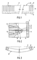
- Fig. 1 is a sectional view of the blank of piezoelectric material from which the transducer is to be formed with the reticulations cut into the front and rear surfaces;
- Fig. 2 is a sectional view of the compression molding apparatus for forming the curved transducer; and
- Fig. 3 is a sectional view of the completed curved piezoelectric transducer.
- Fig. 1 illustrates the blank 10 of PZT material used to form the finished piezoelectric transducer. Blank 10 is in the form of a cylindrical disc and includes a
front side 12, a rear side 14 and asidewall 16.Blank 10 may be any suitable piezoelectric material such as a ceramic. A small grain high density material is particularly suited to making the fine composite structure needed for the finished transducer. Preferably,front side 12 of blank 10 is lapped in order to eliminate any microscopic surface cracks which may have damaged the ceramic. - Since blank 10 will ultimately be molded into a compound curve during the compression molding process, portions of the blank will crack when molded. Accordingly, in order to ensure that blank 10 cracks in a uniform manner its rear side 14 is reticulated with a series of
grooves 18.Grooves 18 are cut in rear side 14 with a fine diamond saw. First a series of parallel cuts are made in the rear side 14 of blank 10. Thereafter blank 10 is rotated 90o and a further series of parallel cuts are made in rear side 14 of blank 10. Accordingly, rear side 14 of blank 10 is "diced" by means ofperpendicular grooves 18. The dicing on rear side 14 is relatively shallow in comparison with the cuts to be made infront side 12 ofblock 10. By way of example only, a sufficient grooving on rear side 14 is 0.2 mm deep cuts spaced 2 mm apart and having a cut width of 0.075 mm. The depth, pitch and position ofgrooves 18 on rear side 14 need not bear any particular relationship to the grooves onfront side 12 as therear side grooves 18 merely permit blank 10 to crack evenly upon molding and the entire rear side 14 of blank 10 will ultimately be completely ground away. - After rear side 14 has been reticulated, the
front side 12 will be reticulated with a series of perpendicular deep, finely pitchedcuts 20. For example only,Cuts 20 may be speced at a pitch of 0.15 mm, have a cut width of 0.075 mm and be 0.9 mm deep. As with rear side 14,front side 12 is first cut with a fine diamond saw in a series of parallel cuts. Thereafter, blank 10 is rotated 90o and another series of cuts is made, perpendicular to the first series of cuts. This will provide a series of ceramic rods upstanding from blank 10 with each rod approximately 75 by 75 by 900 micrometers in length. These rods will be all that remains of the PZT material when the transducer is completed. - The next step in the present method is the filling of the
grooves 20 with a curable polymeric resin (epoxy) and is accomplished with the aid of a centrifuge. A suitable epoxy for this application is a high viscosity, low shrinkage epoxy. It has been found that the viscosity of the epoxy is inversely proportional to its shrinkage. That is, a high viscosity epoxy will have low shrinkage which is an important factor when forming a curved transducer of relatively large diameter. However, since the epoxy has a high viscosity it will not fillgrooves 20 by itself. Accordingly, a centrifuge is used to fill the grooves with epoxy. Thefront side 12 of blank 10 is coated with epoxy and then placed in a centrifuge with rear side 14 facing outwardly in the centrifuge. When the centrifuge rotates the epoxy resin is drawn intogrooves 20. The resin should cover the tops ofrods 22. After the epoxy has been disposed within thegrooves 20, the epoxy is partially cured by letting the epoxy filled blank 10 stand at room temperature. When only partially cured, the epoxy resin will flow during compression molding. - Figure 2 illustrates the apparatus for the compression molding of blank 10.
Blank 10 is disposed above a die 26 having a sphericalconcave depression 28. Die 26 is held in alower die holder 30 which is joined by a fastener 32 to anupper die holder 34. Die 26 includes an air inlet 36 which is coupled for liquid communication to apressure inlet 38 inlower die holder 30.Upper die holder 34 includes anupper pressure inlet 40. As shown in Fig. 2, epoxy filledtransducer 10 is disposed above die 26 and is covered with athin rubber diaphragm 42. -
Upper pressure inlet 40 is connected to an air (or other fluid) line which admits a pressure of approximately 80 psi. The pressure ondiaphragm 42 forces transducer blank 10 to bend down along the contour of the die 26. Thetransducer blank 10 is allowed to remain in the mold under pressure for 24 hours which will permit the epoxy to fully cure. Bubbles trapped in the epoxy resin can be removed by admitting 80 psi to lower diepressure inlet 38 with the pressure to theupper die inlet 40 simultaneously raised to 160 psi. After remaining in die 26 for 24 hours, the epoxy will fully cure and the transducer will remain curved when pressure is removed. After removal from the die 26, the transducer may be given a post curing treatment at elevated temperature to develop the full properties of the epoxy resin. The molded transducer is now ready for grinding. - After removal from die 26 the transducer will have a concave spherical
front surface 12 and a convex rear surface 14. Rear surface 14 will have cracked alonggrooves 18 and rear surface 14 will have a number of rectangular blocks of piezoelectric material betweenperpendicular grooves 18. Extending from the blocks arerods 22 which are now arranged so that they point towards the focal point oftransducer 10. In order to complete the transducer, the rear portion 14 oftransducer 10 is ground away and the excess epoxy extending aboverods 20 on concavefront face 12 must also be ground away. - The grinding of
transducer 10 may be accomplished by hand grinding against curved laps or in a lens generating machine. The rear convex side 14 is ground to the appropriate radius until all of the blocks formed by the cracking alongperpendicular grooves 18 are removed, leaving onlyrods 22 upstanding in the matrix of epoxy. Similarly,front surface 10 is ground away until the tops of therods 22 are flush with the top surface. Accordingly, the completed transducer is shown in Figure 3 in which eachrod 22 is separate from the others and is dispersed in a spherically curved matrix of epoxy. Thereafter the edges oftransducer 10 may be ground into the appropriate cylindrical shape, by for example, a rotary edge grinder. - After completion of the grinding, electrodes are deposited on both sides of
transducer 10 by any suitable method such as thermoevaporation. The electrodes also can be deposited by sputtering or other known metal deposition methods. The convex rear side electrodes are cut through by scribing to form annular ring electrodes. Such scribing may be accomplished on a small engine lathe and cut with a cutting tool. The number of electrodes may vary depending upon the type of transducer required, after scribing each of the electrodes on the convex rear side 14 are electrically isolated from each other. Finally, an acoustic matching layer may be applied to the concaveforward surface 12. The acoustic matching layer may be any suitable material with a suitable acoustic impedance, such as epoxy which may be applied tofront surface 10 and cured as appropriate. - A spherically curved piezoelectric composite transducer was manufactured form a Honeywell 278 ceramic disc of 22mm diameter by 1.5mm thickness. The disc was lapped to 1.2mm thickness before cutting. The rear side was reticulated with a series of 0-075mm wide slots spaced 2mm apart and 0.2mm deep. Thereafter the blank was rotated and a second series of identical perpendicular grooves was cut in the rear surface of the block. The front surface of the blank was diced with 0.075 wide grooves which were 0.9mm deep at a pitch of 0.150. The slots were cut with a rotary diamond blade.
- The epoxy used to fill the grooves on the front surface was Stycast No. 2057 epoxy which has a viscosity of 3500 cps. The epoxy was mixed 100 parts by weight of Stycast No. 2057 resin with seven parts by weight of catalyst No. 9. A centrifuge was used to fill the grooves and thereafter the epoxy was partially cured for four hours at room temperature. The partially cured transducer was compression molded to a 70mm radius of curvature with 80psi pressure. The epoxy was left to cure in the mold for 24 hours. After removal from the die, the transducer was given a four hour post-cure at 80oC. Thereafter the rear surface of the transducer and the front surface was ground to the appropriate dimensions. Gold electrodes were deposited on the front surface and a matching layer of Araldite 502 epoxy was used as the acoustic matching layer.
- The transducer was operated at 3MHz and was found to have high electro-mechanical coupling (kt = 0.57) and low acoustic impedance (12 Mrayl). The transducer produced is an efficient broadband transducer particulalry suited for medical imaging. The array elements, defined by the electrode pattern alone, exhibit low cross-coupling between adjacent elements. Good lateral resolution over a large range of depths can be achieved when used with electronically swept focusing. The transducer manufactured by the above described process also demonstrated proper impulse response.
- Although the present invention has been described in conjunction with a preferred embodiment, it is to be understood that modifications and variations may be resorted to without departing from the spirit and scope of the invention, as those skilled in the art will readily understand. Such modifications and variations are considered to be within the purview and scope of the invention and the appended claims.
Claims (8)
reticulating the rear side of said blank with a series of grooves;
reticulating the front side of said material with a series of relatively deep grooves to provide a matrix of upstanding piezoelectric rods;
filling the spaces between the piezoelectric rods on the front side of said blank with a curable polymeric resin;
partially curing said resin filling the spaces between said rods on the front side of said blank;
compression molding said blank into a curve, with said front side being concave and said rear side being convex;
curing said resin while holding said molded blank in said curved shape until said resin has cured; and
removing said back side of said blank to provide a spherically curved transducer having a multiplicity of individual piezoelectric rods disposed in a matrix of cured polymeric resin.
Applications Claiming Priority (2)
| Application Number | Priority Date | Filing Date | Title |
|---|---|---|---|
| US219520 | 1980-12-23 | ||
| US07/219,520 US4869768A (en) | 1988-07-15 | 1988-07-15 | Ultrasonic transducer arrays made from composite piezoelectric materials |
Publications (3)
| Publication Number | Publication Date |
|---|---|
| EP0351015A2 true EP0351015A2 (en) | 1990-01-17 |
| EP0351015A3 EP0351015A3 (en) | 1991-09-25 |
| EP0351015B1 EP0351015B1 (en) | 1995-01-04 |
Family
ID=22819603
Family Applications (1)
| Application Number | Title | Priority Date | Filing Date |
|---|---|---|---|
| EP89201819A Expired - Lifetime EP0351015B1 (en) | 1988-07-15 | 1989-07-10 | A method for fabricating a piezoelectric composite transducer |
Country Status (4)
| Country | Link |
|---|---|
| US (1) | US4869768A (en) |
| EP (1) | EP0351015B1 (en) |
| JP (1) | JPH0267099A (en) |
| DE (1) | DE68920370T2 (en) |
Cited By (5)
| Publication number | Priority date | Publication date | Assignee | Title |
|---|---|---|---|---|
| EP0458092A2 (en) * | 1990-05-21 | 1991-11-27 | Acoustic Imaging Technologies Corporation | Curved array ultrasonic transducer assembly and its method of manufacture |
| EP1452141A1 (en) * | 2003-02-26 | 2004-09-01 | HMT High Medical Technologies AG | Shock wave generating device |
| US7804228B2 (en) | 2007-12-18 | 2010-09-28 | Boston Scientific Scimed, Inc. | Composite passive materials for ultrasound transducers |
| CN105702851A (en) * | 2014-11-28 | 2016-06-22 | 中国科学院深圳先进技术研究院 | 2-2 type piezoelectric composite material and preparation method thereof |
| CN109760243A (en) * | 2018-12-28 | 2019-05-17 | 广州瑞派医疗器械有限责任公司 | Convex configuration ultrasonic transducer manufacturing equipment and method |
Families Citing this family (29)
| Publication number | Priority date | Publication date | Assignee | Title |
|---|---|---|---|---|
| US5131382A (en) * | 1989-03-27 | 1992-07-21 | Meyer William F | Endoscopic percutaneous discectomy device |
| US5065068A (en) * | 1989-06-07 | 1991-11-12 | Oakley Clyde G | Ferroelectric ceramic transducer |
| DE3932959C1 (en) * | 1989-10-03 | 1991-04-11 | Richard Wolf Gmbh, 7134 Knittlingen, De | |
| US5424596A (en) * | 1992-10-05 | 1995-06-13 | Trw Inc. | Activated structure |
| US6252334B1 (en) | 1993-01-21 | 2001-06-26 | Trw Inc. | Digital control of smart structures |
| US5525853A (en) * | 1993-01-21 | 1996-06-11 | Trw Inc. | Smart structures for vibration suppression |
| US5423220A (en) * | 1993-01-29 | 1995-06-13 | Parallel Design | Ultrasonic transducer array and manufacturing method thereof |
| US5412854A (en) * | 1993-06-18 | 1995-05-09 | Humphrey Instruments, Inc. | Method of making a high frequency focused transducer |
| US5792058A (en) * | 1993-09-07 | 1998-08-11 | Acuson Corporation | Broadband phased array transducer with wide bandwidth, high sensitivity and reduced cross-talk and method for manufacture thereof |
| US5415175A (en) * | 1993-09-07 | 1995-05-16 | Acuson Corporation | Broadband phased array transducer design with frequency controlled two dimension capability and methods for manufacture thereof |
| US5743855A (en) * | 1995-03-03 | 1998-04-28 | Acuson Corporation | Broadband phased array transducer design with frequency controlled two dimension capability and methods for manufacture thereof |
| GB2287375B (en) | 1994-03-11 | 1998-04-15 | Intravascular Res Ltd | Ultrasonic transducer array and method of manufacturing the same |
| US5684884A (en) * | 1994-05-31 | 1997-11-04 | Hitachi Metals, Ltd. | Piezoelectric loudspeaker and a method for manufacturing the same |
| US5730113A (en) * | 1995-12-11 | 1998-03-24 | General Electric Company | Dicing saw alignment for array ultrasonic transducer fabrication |
| US7226417B1 (en) | 1995-12-26 | 2007-06-05 | Volcano Corporation | High resolution intravascular ultrasound transducer assembly having a flexible substrate |
| US5942137A (en) * | 1997-08-29 | 1999-08-24 | Scitex Corporation Ltd. | Method and apparatus for laser scribing grooves on hard crystals |
| DE19954020C2 (en) * | 1999-11-10 | 2002-02-28 | Fraunhofer Ges Forschung | Method of manufacturing a piezoelectric transducer |
| US6726631B2 (en) * | 2000-08-08 | 2004-04-27 | Ge Parallel Designs, Inc. | Frequency and amplitude apodization of transducers |
| US7348712B2 (en) * | 2004-04-16 | 2008-03-25 | Kabushiki Kaisha Toshiba | Ultrasonic probe and ultrasonic diagnostic apparatus |
| JP4469928B2 (en) * | 2004-09-22 | 2010-06-02 | ベックマン・コールター・インコーポレーテッド | Stirring vessel |
| JPWO2007113907A1 (en) * | 2006-04-05 | 2009-08-13 | 住友金属工業株式会社 | Ultrasonic probe, ultrasonic flaw detection method and ultrasonic flaw detection apparatus |
| US8093782B1 (en) | 2007-08-14 | 2012-01-10 | University Of Virginia Patent Foundation | Specialized, high performance, ultrasound transducer substrates and related method thereof |
| US20100171395A1 (en) * | 2008-10-24 | 2010-07-08 | University Of Southern California | Curved ultrasonic array transducers |
| US9364863B2 (en) * | 2013-01-23 | 2016-06-14 | Siemens Medical Solutions Usa, Inc. | Method for forming an ultrasound transducer array |
| DE102017111624A1 (en) * | 2017-05-29 | 2018-11-29 | Endress + Hauser Flowtec Ag | ultrasound transducer |
| CN112008959B (en) * | 2020-08-18 | 2022-02-18 | 长安大学 | Device and method for bending FRP (fiber reinforced plastic) ribs on site |
| CN112206004B (en) * | 2020-09-25 | 2023-08-25 | 飞依诺科技股份有限公司 | Ultrasonic probe and method of manufacturing the same |
| DE102022003089A1 (en) | 2022-08-23 | 2024-02-29 | Mercedes-Benz Group AG | Signal output device and motor vehicle with such a signal output device |
| CN116973458B (en) * | 2023-09-25 | 2023-12-15 | 中北大学 | Preparation method of piezoelectric composite material array structure |
Citations (3)
| Publication number | Priority date | Publication date | Assignee | Title |
|---|---|---|---|---|
| US3496617A (en) * | 1967-11-08 | 1970-02-24 | Us Navy | Technique for curving piezoelectric ceramics |
| JPS59229999A (en) * | 1983-06-10 | 1984-12-24 | Matsushita Electric Ind Co Ltd | Manufacture of ultrasonic probe |
| US4683396A (en) * | 1983-10-17 | 1987-07-28 | Hitachi, Ltd. | Composite ultrasonic transducers and methods for making same |
Family Cites Families (6)
| Publication number | Priority date | Publication date | Assignee | Title |
|---|---|---|---|---|
| US4250603A (en) * | 1979-04-30 | 1981-02-17 | Honeywell Inc. | Method of making electroded wafer for electro-optic devices |
| US4281550A (en) * | 1979-12-17 | 1981-08-04 | North American Philips Corporation | Curved array of sequenced ultrasound transducers |
| SU1235431A1 (en) * | 1984-01-27 | 1987-10-07 | Всесоюзный Научно-Исследовательский Институт По Разработке Неразрушающих Методов И Средств Контроля Качества Материалов | Method of producing focusing acoustic converters |
| US4658176A (en) * | 1984-07-25 | 1987-04-14 | Hitachi, Ltd. | Ultrasonic transducer using piezoelectric composite |
| JPH0660896B2 (en) * | 1984-11-02 | 1994-08-10 | 株式会社日立製作所 | Ultrasonic probe |
| US4788096A (en) * | 1985-06-06 | 1988-11-29 | Hoechst Celanese Corporation | Devices for making piezoelectric ceramic or ceramic-base composite sensors |
-
1988
- 1988-07-15 US US07/219,520 patent/US4869768A/en not_active Expired - Fee Related
-
1989
- 1989-07-10 DE DE68920370T patent/DE68920370T2/en not_active Expired - Fee Related
- 1989-07-10 EP EP89201819A patent/EP0351015B1/en not_active Expired - Lifetime
- 1989-07-12 JP JP1178183A patent/JPH0267099A/en active Pending
Patent Citations (3)
| Publication number | Priority date | Publication date | Assignee | Title |
|---|---|---|---|---|
| US3496617A (en) * | 1967-11-08 | 1970-02-24 | Us Navy | Technique for curving piezoelectric ceramics |
| JPS59229999A (en) * | 1983-06-10 | 1984-12-24 | Matsushita Electric Ind Co Ltd | Manufacture of ultrasonic probe |
| US4683396A (en) * | 1983-10-17 | 1987-07-28 | Hitachi, Ltd. | Composite ultrasonic transducers and methods for making same |
Non-Patent Citations (2)
| Title |
|---|
| IEEE 1988 ULTRASONICS SYMPOSIUM, Chicago, Illinois, 2nd - 5th October 1988, vol. 1, pages 789-793, IEEE, New York, US; F.R. MONTERO DE ESPINOSA et al.: "First stages on the development of a 3D echocardiographic system for aerospace purposes" * |
| PATENT ABSTRACTS OF JAPAN, vol. 9, no. 106 (E-313)[1829], 10th May 1985; & JP-A-59 229 999 (MATSUSHITA) 24-12-1984 * |
Cited By (8)
| Publication number | Priority date | Publication date | Assignee | Title |
|---|---|---|---|---|
| EP0458092A2 (en) * | 1990-05-21 | 1991-11-27 | Acoustic Imaging Technologies Corporation | Curved array ultrasonic transducer assembly and its method of manufacture |
| EP0458092A3 (en) * | 1990-05-21 | 1993-01-20 | Acoustic Imaging Technologies Corporation | Curved array ultrasonic transducer assembly and its method of manufacture |
| EP1452141A1 (en) * | 2003-02-26 | 2004-09-01 | HMT High Medical Technologies AG | Shock wave generating device |
| US7867178B2 (en) | 2003-02-26 | 2011-01-11 | Sanuwave, Inc. | Apparatus for generating shock waves with piezoelectric fibers integrated in a composite |
| US7804228B2 (en) | 2007-12-18 | 2010-09-28 | Boston Scientific Scimed, Inc. | Composite passive materials for ultrasound transducers |
| CN105702851A (en) * | 2014-11-28 | 2016-06-22 | 中国科学院深圳先进技术研究院 | 2-2 type piezoelectric composite material and preparation method thereof |
| CN105702851B (en) * | 2014-11-28 | 2018-09-25 | 中国科学院深圳先进技术研究院 | 2-2 type piezo-electricity composite materials and preparation method thereof |
| CN109760243A (en) * | 2018-12-28 | 2019-05-17 | 广州瑞派医疗器械有限责任公司 | Convex configuration ultrasonic transducer manufacturing equipment and method |
Also Published As
| Publication number | Publication date |
|---|---|
| DE68920370T2 (en) | 1995-07-27 |
| EP0351015A3 (en) | 1991-09-25 |
| EP0351015B1 (en) | 1995-01-04 |
| US4869768A (en) | 1989-09-26 |
| JPH0267099A (en) | 1990-03-07 |
| DE68920370D1 (en) | 1995-02-16 |
Similar Documents
| Publication | Publication Date | Title |
|---|---|---|
| EP0351015B1 (en) | A method for fabricating a piezoelectric composite transducer | |
| US5164920A (en) | Composite ultrasound transducer and method for manufacturing a structured component therefor of piezoelectric ceramic | |
| US6791240B2 (en) | Ultrasonic transducer apparatus | |
| EP0137529B1 (en) | Method for fabricating composite electrical transducers | |
| Smith | The role of piezocomposites in ultrasonic transducers | |
| US6183578B1 (en) | Method for manufacture of high frequency ultrasound transducers | |
| EP1318551B1 (en) | Composite piezoelectric element and method of fabricating the same | |
| AU655091B2 (en) | Method for making piezoelectric composites | |
| EP1227525B1 (en) | Piezocomposite, ultrasonic probe for ultrasonic diagnostic equipment, ultrasonic diagnostic equipment and method for producing piezocomposite | |
| EP2024294B1 (en) | Processing piezoelectric material | |
| US4348904A (en) | Acoustic impedance matching device | |
| US5376859A (en) | Transducers with improved signal transfer | |
| US6081979A (en) | Method of making a transducing composite of sintered piezoelectric ceramic granules in a polymer matrix | |
| CN85102335A (en) | Composite ultrasonic transducers and manufacture method thereof | |
| US5841736A (en) | Low voltage piezoelectric transducer and method | |
| EP1496553B1 (en) | Composite piezoelectric body | |
| CN115007430B (en) | Spherical ultrasonic transducer manufacturing method and ultrasonic transducer | |
| Lubitz et al. | Microstructuring technology | |
| JPH0475718B2 (en) | ||
| JP2004039836A (en) | Composite piezoelectric body and its manufacturing method | |
| JPH11276480A (en) | Composite piezoelectric vibrator and manufacture therefor | |
| JPH04200098A (en) | Production of composite piezoelectric | |
| JPH0486100A (en) | Ultrasonic probe and its manufacture | |
| JPH07303637A (en) | Ultrasonic probe and method for producing the same | |
| Seyed-Bolorforosh | Novel integrated impedance matching layer |
Legal Events
| Date | Code | Title | Description |
|---|---|---|---|
| PUAI | Public reference made under article 153(3) epc to a published international application that has entered the european phase |
Free format text: ORIGINAL CODE: 0009012 |
|
| AK | Designated contracting states |
Kind code of ref document: A2 Designated state(s): DE FR GB |
|
| PUAL | Search report despatched |
Free format text: ORIGINAL CODE: 0009013 |
|
| AK | Designated contracting states |
Kind code of ref document: A3 Designated state(s): DE FR GB |
|
| 17P | Request for examination filed |
Effective date: 19920324 |
|
| 17Q | First examination report despatched |
Effective date: 19940208 |
|
| GRAA | (expected) grant |
Free format text: ORIGINAL CODE: 0009210 |
|
| AK | Designated contracting states |
Kind code of ref document: B1 Designated state(s): DE FR GB |
|
| REF | Corresponds to: |
Ref document number: 68920370 Country of ref document: DE Date of ref document: 19950216 |
|
| ET | Fr: translation filed | ||
| PG25 | Lapsed in a contracting state [announced via postgrant information from national office to epo] |
Ref country code: GB Effective date: 19950710 |
|
| PLBE | No opposition filed within time limit |
Free format text: ORIGINAL CODE: 0009261 |
|
| STAA | Information on the status of an ep patent application or granted ep patent |
Free format text: STATUS: NO OPPOSITION FILED WITHIN TIME LIMIT |
|
| 26N | No opposition filed | ||
| GBPC | Gb: european patent ceased through non-payment of renewal fee |
Effective date: 19950710 |
|
| PG25 | Lapsed in a contracting state [announced via postgrant information from national office to epo] |
Ref country code: DE Effective date: 19960402 |
|
| PG25 | Lapsed in a contracting state [announced via postgrant information from national office to epo] |
Ref country code: FR Effective date: 19960430 |
|
| REG | Reference to a national code |
Ref country code: FR Ref legal event code: ST |
|
| REG | Reference to a national code |
Ref country code: FR Ref legal event code: ST |
|
| REG | Reference to a national code |
Ref country code: FR Ref legal event code: ST |