EP0352725A2 - Numerical controller for machining a non-circular workpiece - Google Patents
Numerical controller for machining a non-circular workpiece Download PDFInfo
- Publication number
- EP0352725A2 EP0352725A2 EP89113680A EP89113680A EP0352725A2 EP 0352725 A2 EP0352725 A2 EP 0352725A2 EP 89113680 A EP89113680 A EP 89113680A EP 89113680 A EP89113680 A EP 89113680A EP 0352725 A2 EP0352725 A2 EP 0352725A2
- Authority
- EP
- European Patent Office
- Prior art keywords
- wheel diameter
- profile data
- wheel
- marginal
- diameter
- Prior art date
- Legal status (The legal status is an assumption and is not a legal conclusion. Google has not performed a legal analysis and makes no representation as to the accuracy of the status listed.)
- Granted
Links
Images


Classifications
-
- B—PERFORMING OPERATIONS; TRANSPORTING
- B24—GRINDING; POLISHING
- B24B—MACHINES, DEVICES, OR PROCESSES FOR GRINDING OR POLISHING; DRESSING OR CONDITIONING OF ABRADING SURFACES; FEEDING OF GRINDING, POLISHING, OR LAPPING AGENTS
- B24B5/00—Machines or devices designed for grinding surfaces of revolution on work, including those which also grind adjacent plane surfaces; Accessories therefor
- B24B5/36—Single-purpose machines or devices
- B24B5/42—Single-purpose machines or devices for grinding crankshafts or crankpins
-
- G—PHYSICS
- G05—CONTROLLING; REGULATING
- G05B—CONTROL OR REGULATING SYSTEMS IN GENERAL; FUNCTIONAL ELEMENTS OF SUCH SYSTEMS; MONITORING OR TESTING ARRANGEMENTS FOR SUCH SYSTEMS OR ELEMENTS
- G05B19/00—Programme-control systems
- G05B19/02—Programme-control systems electric
- G05B19/18—Numerical control [NC], i.e. automatically operating machines, in particular machine tools, e.g. in a manufacturing environment, so as to execute positioning, movement or co-ordinated operations by means of programme data in numerical form
- G05B19/182—Numerical control [NC], i.e. automatically operating machines, in particular machine tools, e.g. in a manufacturing environment, so as to execute positioning, movement or co-ordinated operations by means of programme data in numerical form characterised by the machine tool function, e.g. thread cutting, cam making, tool direction control
- G05B19/184—Generation of cam-like surfaces
-
- G—PHYSICS
- G05—CONTROLLING; REGULATING
- G05B—CONTROL OR REGULATING SYSTEMS IN GENERAL; FUNCTIONAL ELEMENTS OF SUCH SYSTEMS; MONITORING OR TESTING ARRANGEMENTS FOR SUCH SYSTEMS OR ELEMENTS
- G05B2219/00—Program-control systems
- G05B2219/30—Nc systems
- G05B2219/45—Nc applications
- G05B2219/45161—Grinding machine
-
- G—PHYSICS
- G05—CONTROLLING; REGULATING
- G05B—CONTROL OR REGULATING SYSTEMS IN GENERAL; FUNCTIONAL ELEMENTS OF SUCH SYSTEMS; MONITORING OR TESTING ARRANGEMENTS FOR SUCH SYSTEMS OR ELEMENTS
- G05B2219/00—Program-control systems
- G05B2219/30—Nc systems
- G05B2219/50—Machine tool, machine tool null till machine tool work handling
- G05B2219/50336—Tool, probe offset for curves, surfaces, contouring
Definitions
- the present invention relates to a numerical controller of a grinding machine for machining a non-circular workpiece such as a cam and the like.
- the position of a grinding wheel is controlled in synchronism with the rotation of a spindle in accordance with profile data which defines the relation between the rotational angle of the spindle and the position of the grinding wheel.
- the profile data is obtained as a changing component of the grinding wheel position which varies with respect to the rotational angle of the spindle.
- the changing component indicates a relative moving locus of the center axis of the grinding wheel when the grinding wheel makes a round tangentially to the periphery of the non-circular workpiece such as a cam and the like.
- the profile data must be, if the present wheel diameter is varied, recalculated from lift data and the present diameter of the grinding wheel. However, if the profile data is calculated whenever the wheel diameter decreases by a small amount, it is time consuming for machining and not realistic.
- the present wheel diameter in practice, reduces gradually by periodical wheel dressings.
- the operator When the wheel diameter reduced by the wheel dressings reaches a marginal diameter whereat the finished shape error of the workpiece exceeds a tolerance if the profile data is not recalculated, the operator must gives commands to the numerical controller to recalculate the profile data from the present diameter of the grinding wheel and lift data.
- the marginal diameter of the grinding wheel at which the finished shape error of the workpiece exceeds a tolerance,changes depending upon the profile of the non-circular workpiece such as the cam and the present wheel diameter, the marginal diameter or the timing of recalculating of the profile data can hardly be determined uniformly.
- the present invention comprises, present wheel diameter memory means for storing the present wheel diameter, machining tolerance input means for inputting a machining tolerance related to a finished shape of the non-circular workpiece, wheel diameter calculating means for calculating the marginal wheel diameter which requires renewal of the profile data from the machining tolerance, profile data calculating means for calculating new profile data from the marginal wheel diameter and lift data, judging means for comparing the marginal wheel diameter and the present wheel diameter to judge whether the latter is larger than the marginal wheel diameter, and profile data renewing means for renewing the profile data used for machining with said new profile data corresponding to the marginal wheel diameter, when the present wheel diameter reaches the marginal wheel diameter.
- the profile data is calculated with a standard wheel diameter
- the workpiece can be machined most precisely with the grinding wheel having the standard wheel diameter.
- finished shape errors of the workpiece increase as the wheel diameter decreases.
- the profile data must be calculated again when the wheel diameter reaches to a marginal wheel diameter which is smaller by a constant rate than the standard wheel diameter from which the profile data was calculated.
- the marginal wheel diameter is calculated by the wheel diameter calculating means.
- the profile data corresponding to the marginal wheel diameter is calculated by the profile data calculating means.
- the profile data used for machining is renewed with new profile data corresponding to the marginal wheel diameter.
- the judging means is designed to judge whether the wheel diameter is larger than the marginal wheel diameter at every dressing of the grinding wheel.
- the wheel diameter calculating means for calculating the marginal wheel diameter comprises, error calculating means for calculating a finished shape error of the workpiece when it is ground with the grinding wheel having the minimum wheel diameter, using the profile data corresponding to the maximum wheel diameter, and another finished shape error of the workpiece when it is ground with the grinding wheel having the medium wheel diameter between the maximum and minimum wheel diameters, using the profile data corresponding to the maximum wheel diameter, means for obtaining the relationship between the finished shape errors and the wheel diameter at any wheel diameter, by quadratic function approximating the finished shape errors at these points of maximum, medium and minimum wheel diameters, and means for deciding the marginal wheel diameter from the quadratic function and the machining tolerance.
- the marginal wheel diameter can be simply obtained by such a configuration.
- Fig. 1 is a block diagram showing a numerically controlled grinding machine, in which the numeral 10 indicates a bed thereof, whereon a table 11 driven by a servo motor 16 via feed screw mechanism 24 is disposed slidably in the direction of Z-axis.
- a head-stock 12 supporting a spindle 13 driven by a servo motor 14 is provided on the table 11.
- a tail stock 15 is mounted, and a cam shaft as a workpiece W is clamped between a center 19 of the tail stock 15 and a center 17 of the spindle 13.
- the workpiece W is engaged to a positioning pin 18 projected from the spindle 13 to be locked in a phase of rotation to the spindle.
- a wheel head 20 which is movable back and forth toward the workpiece W is guided and provided with a grinding wheel G driven by a motor 21.
- the wheel head 20 is coupled to a servo motor 23 via a feed screw 25, and moved back and forth in the direction of X-axis by the servo motor 23 rotating forward or reverse.
- Drive units 50, 51 and 52 are circuits for receiving command pulses from a numerical controller 30 to drive the servo motors 23, 14 and 16 respectively.
- the numerical controller 30 mainly controls the rotation of the control axes numerically to control grinding of the workpiece W and dressing of the grinding wheel G.
- the numerical controller 30 mainly comprises a main CPU 31 for controlling the grinding machine, a ROM 33 storing the control program and a RAM 32 for storing input data.
- a machining NC profile data area 321 for storing the NC profile data and an NC program area 322 for storing the NC program for machining the workpiece, using the NC profile data stored in the NC profile data area 321 are formed.
- a drive CPU 36, a RAM 35 and a pulse distributing circuit 37 are as a driving system for the servo motors 23, 14 and 16.
- the RAM 35 is a memory to which positioning data of the grinding wheel G, table 11 and spindle 13 are inputted from the main CPU 31.
- the drive CPU 36 executes the process of the slow-up, slow-down and interpolation to the target point with respect to the control axes, and outputs positioning data of the interpolation point periordically, and the pulse distributing circuit 37 outputs operation command pulses to respective drive units 50, 51 and 52 in accordance with the positioning data output from the drive CPU36.
- the numeral 70 designates an automatic programming apparatus connected to the numerical controller 30 and automatically generating profile data P i from the polar coordinate lift data L0 and the wheel diameter R i .
- the automatic programming apparatus 70 comprises a front CPU 71, a RAM 72 and an input-output interface 73.
- the RAM 72 has a lift data area 721 for storing the lift data of a plurality of workpieces, a polar coordinate lift data area 722 for storing the polar coordinate lift data L0 converted from the lift data, a machining tolerance area 723 for storing a machining tolerance , a marginal wheel diameter area 724 for storing a marginal wheel diameter SR i upon which a renewal timing for the machining profile data is determined, a profile data area 725 for storing the profile data corresponding to the marginal wheel diameter SR i , and a present wheel diameter memory data area 726 for storing the present wheel diameter R i transferred from the main CPU 31 to the front CPU 71 whenever the grinding wheel G is dressed at a predetermined cycle.
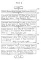
- Fig. 3 shows a base routine program of the front CPU 71 which judges commands inputted from a keyboard 44 and the main CPU 31, and branches to the various processing routines.
- Step 200 of Fig. 3 whether a command instructing a generation of the profile data P0 is given from the keyboard by the operator or not is determined.
- processings shown in Fig. 4 are executed by the front CPU 71.
- Step 300 all flat tappet lift data necessary for machining are read from a tape reader 42 via the input-output interface 73 and stored in the lift data area 721. Also, various data such as the workpiece number, minimum wheel diameter Rmin and maximum wheel diameter Rmax as the initial value of the wheel diameter are read via tape reader 42 and the keyboard 44 and stored in a predetermined area in the RAM 72. Then, in the next Step 301, the machining tolerance inputted from of the keyboard 44 by the operator is read and stored in the machining tolerance area 723.
- Step 302 the flat tappet lift data corresponding to the number of the workpiece to be machined which has been designated by the operator, is read from the lift data area 721 and converted into the polar coordinate lift data L0, which is stored in the polar coordinate lift data area 722.
- the flat tappet lift data is represented by a moving amount, i.e., a lift amount of the flat tappet 3 which is, when the cam 1 is rotated, contacted with the cam 1 and movable in the direction of X-axis.
- the rotational angle ⁇ of the cam 1 is defined by the rotational angle of the reference point K on the base circle 2
- the lift amount ⁇ x ( ⁇ ) is obtained as a function of ⁇ .
- the lift data to be input is given, for example, in point sequence of the lift amount ⁇ x ( ⁇ ) at every rotational angle of 0.5°. Since the contact position of the flat tappet 3 with the cam 1 varies responsive to the rotation of the cam 1, the lift data by the flat tappet is not given by the point sequence at every equicentral angle on the profile line of the cam 1.
- the flat tappet lift data as shown in Fig. 10B, is converted into the polar coordinate lift data L0 specifying the point sequence on the profile line of the cam 1 by the central angle ⁇ and the length r( ⁇ ) of the radius vector with taking into account of the contact relation between the flat tappet 3 and the cam 1 as shown in Fig. 10A.
- the CPU 31 moves its procedure to Step 303, wherein the profile data P0 is calculated from the polar coordinate lift data L0 and the maximum wheel diameter Rmax which is the initial wheel diameter.
- the profile data P0 is obtained as shown in Fig. 10 C.
- the polar coordinate lift data L0 is smoothly interpolated to obtain the lift data at discrete points H1, H2, ... H n at every equicentral angle on the profile line of the cam 1.
- Step 304 processings of the front CPU 71 are moved to Step 304, wherein the profile data P0 is stored, as the initial profile data, in the NC profile data area 321 via the main CPU 31.
- Step 305 the marginal wheel diameters SR1, SR2, SR3 are calculated and stored in a predetermined area in the RAM 72, and in the following Step 306, the first marginal wheel diameter SR1 is set in the marginal wheel diameter area 724 as the wheel diameter upon which the next renewal timing of the profile data is decided.
- the medium wheel diameter Rmid is calculated as a mean value between the minimum wheel diameter Rmin possible to grind at and the maximum wheel diameter Rmax as the initial value of the grinding wheel.
- a polar coordinate lift data L1 is calculated back from the profile data P0 corresponding to the maximum wheel diameter Rmax and the medium wheel diameter Rmid.
- the polar coordinate lift data L1 corresponds to the finished shape of the workpiece when the workpiece is ground with the grinding wheel of the medium wheel diameter Rmid using the profile data P0.
- Step 402 a polar coordinate lift data L2 is calculated back from the profile data P0 corresponding to the maximum wheel diameter Rmax and the minimum wheel diameter Rmin.
- the polar coordinate lift data L2 corresponds to the finished shape of the workpiece when the workpiece is ground with the grinding wheel of the minimum wheel diameter Rmin using the profile data P0.
- the polar coordinate lift data L1 is obtained as shown in Fig. 11.
- a locus of grinding wheel center decided by the profile data P0 related to the maximum wheel diameter Rmax is defined as M
- point U i spaced toward the spindle by the medium wheel diameter Rmid in the direction normal to the locus M1 from the arbitrary point S i on the locus M1 is obtained.
- a locus drawn by the point U i is the finished shape from which the polar coordinate lift data L1 is calculated.
- the finished shape from which the polar coordinate lift data L2 is calculated can be obtained in a same manner.
- the polar coordinate lift data L0 corresponds to the maximum wheel diameter Rmax. Characteristics of these data L0, L1 and L2 related to the cam rotational angle ⁇ are shown in Fig. 12. It is recognized that deviation from the ideal finished shape corresponding to the polar coordidnate lift data L0 is larger as the wheel diameter reduces. As the wheel diameter reduces, a phase advance in a area from the base circle to the top and phase lag in a area from the top to the base circle tend to increase.
- a finished shape error ERR1 is calculated from a maximum value of an absolute value of the difference between the polar coordinate lift data L1( ⁇ ) and the polar coordinate lift data L0( ⁇ ) with respect to the rotational angle of the cam. That is, the error ERR1 is obtained from the following equation.
- ERR1 Max.
- a finished shape error ERR2 is calculated from a maximum value of an absolute value of the difference between the polar coordinate lift data L2( ⁇ ) and the polar coordinate lift data L0( ⁇ ) by using following eauation.
- ERR2 Max.
- three preliminary wheel diameters PR1 , PR2 and PR3 whereat the finished shape error reaches to ⁇ , 2 ⁇ and 3 ⁇ , respectively, are first obtained.
- wheel diameters, which are larger than the preliminary wheel diameter PR1 , PR2 and PR3, respectively and coincide with the nearest ones of discrete wheel diameters with a distance of the dressing allowance D of the grinding wheel are serched as the marginal diameters SR1, SR2 and SR3.
- each of the marginal wheel diameters is used for determining the renewal timing of the profile data used for machining. In such a manner, the marginal wheel diameters are obtained all together.
- Step 500 a workpiece W is ground in accordance with a NC program stored in the NC program area 322. That is, together with feeding of the grinding wheel G commanded by the NC program, profile data in the NC profile data area 321 are commanded to be read, as a result, a cutting-in movement and a profile generating motion of the grinding wheel G are performed simultaneously and the workpiece is ground into a predetermined shape.
- Step 501 the CPU 31 moves its procedures to Step 501 to determine whether the grinding wheel G has been dressed during or after machining according to the NC program.
- Step 502 a new present wheel diameter R i is obtained by subtracting the dressing allowance D from the present wheel diameter R i .
- Step 503 the new present wheel diameter R i is transferred to the front CPU 71, and thereby stored in the present wheel diameter data area 726.
- Step 504 the main CPU31 commands the front CPU71 to judge whether the machining error is within the tolerance ⁇ if the workpiece W is machined with the grinding wheel having diameter R i .
- Step 600 the present wheel diameter R i transferred from the main CPU 31 and stored in the present wheel diameter data area 726 is read. Then, in Step 601, it is determined whether the present wheel diameter R i is not less than the marginal wheel diameter SR i (initially, the first marginal wheel diameter SR i is stored) stored in the marginal wheel diameter area 724. When it is YES, since the profile data is not necessary to be recalculated, the procedure is moved to Step 606 and a processing end signal is output to the CPU 31 to complete the program.
- Step 601 While, when it is determined NO in Step 601, that is, when the present wheel diameter R i becomes less than the marginal wheel diameter SR i , the CPU 31 moves its procedure to Step 602 to calculate the profile data P i with the marginal wheel diameter SR i and the polar coordinate lift data L0. Then, in Step 603, the profile data area 725 is rewritten with the profile data newly calculated in Step 602.
- Step 604 new profile data P i stored in the profile data area 725 is transferred to the main CPU 31 via the front CPU 71 and stored in the NC profile data area 321.
- Step 605 the next marginal wheel diameter SR i+1 is stored in the marginal wheel diameter area 724.
- the marginal wheel diameter SR i to have been set is SR1
- the marginal wheel diameter SR i+1 to be set next becomes SR2
- the processing end signal is outputted to the main CPU 31 to complete the program.
- Step 505 it is determined whether new profile data P i has been transferred. If it is determined YES, the procedure is moved to next Step 506, wherein the transferred profile data P i is stored in the NC profile data area 321 to renew profile data used for machining. Then, in Step 507, it is determined whether all of the machining are completed, if the result is YES, the program is completed, and if the result is NO, processings of the main CPU 31 return again to the aforesaid Step 500.
- the marginal wheel diameter SR1, SR2, SR3 are obtained, they are obtained all together by calculating the wheel diameters at which the finished shape errors are brought to multiples of the machining tolerance ⁇ , from the quadratic function which approximates the relationship between the finished shape error and wheel diameter, passing through the three-point value of maximum finished shape errors to be caused if work-piece is machined with the grinding wheel having the maximum Rmax, medium Rmid and minimum Rmin wheel diameters, respectively, using the profile data P0 corresponding to the maximum wheel diameter Rmax.
- the second marginal wheel diameter SR2 when it is obtained, it may be obtained by calculating the wheel diameter at which the finished shape error is brought to the machining tolerance ⁇ , from a quadratic function which approximates the relationship between the finished shape error and wheel diameter, passing through the three-point value of the finished shape errors to be caused if the workpiece is machined with the grinding wheel having the first marginal wheel diameter SR1, medium wheel diameter Rmid and minimum wheel diameter Rmin, respectively, using the profile data P1 related to the first marginal wheel diameter SR1, by defining the mean value between the first marginal wheel diameter SR1 and the minimum wheel diameter Rmin as the new medium wheel diameter Rmid.
- the third marginal wheel diameter SR3 can also be obtained similarly. That is, when obtaining the next marginal wheel diameter, profile data presently used are used to obtain the finished shape errors.
- the method of interpolation of errors is not limited to quadratic functional interpolation aforementioned.
- the workpiece can be machined without renewing the profile data for machining until the machining error becomes larger than a predetermined tolerance, so that the cycle time can be shortened on account of no wastefull recalculating of the profile data.
- machining accuracy of the workpiece after machining can be kept constant within the tolerance.
- the profile data used for machining must be renewed with new profile data corresponding to the present diameter of the grinding wheel.
- optimum wheel diameters, at which new profile data must be calculated are decided automatically.
- the numerical controller calculates the marginal diameters which require renewal of profile data based upon the machining tolerance when a new grinding wheel is attached to the wheel head. After that, the numerical controller calculates new profile data from the marginal wheel diameter and lift data, when the present wheel diameter reaches into one of the marginal wheel diameters. The old profile data is renewed with the newly calculated profile data corresponding to the marginal wheel diameter.
Abstract
Description
- The present invention relates to a numerical controller of a grinding machine for machining a non-circular workpiece such as a cam and the like.
- In a conventional grinding machine of this kind, the position of a grinding wheel is controlled in synchronism with the rotation of a spindle in accordance with profile data which defines the relation between the rotational angle of the spindle and the position of the grinding wheel. The profile data is obtained as a changing component of the grinding wheel position which varies with respect to the rotational angle of the spindle. The changing component indicates a relative moving locus of the center axis of the grinding wheel when the grinding wheel makes a round tangentially to the periphery of the non-circular workpiece such as a cam and the like. When the wheel diameter decreases on account of wear, the changing component is varied, since the contact point between the wheel and the cam does not stay on the plane formed by the spindle and the rotary shaft of the wheel and changes depending on the wheel diameter as well as the rotational angle position of the workpiece. Accordingly, in order to accurately grind workpieces, the profile data must be, if the present wheel diameter is varied, recalculated from lift data and the present diameter of the grinding wheel. However, if the profile data is calculated whenever the wheel diameter decreases by a small amount, it is time consuming for machining and not realistic.
- The present wheel diameter, in practice, reduces gradually by periodical wheel dressings. When the wheel diameter reduced by the wheel dressings reaches a marginal diameter whereat the finished shape error of the workpiece exceeds a tolerance if the profile data is not recalculated, the operator must gives commands to the numerical controller to recalculate the profile data from the present diameter of the grinding wheel and lift data.
- However, since the marginal diameter of the grinding wheel, at which the finished shape error of the workpiece exceeds a tolerance,changes depending upon the profile of the non-circular workpiece such as the cam and the present wheel diameter, the marginal diameter or the timing of recalculating of the profile data can hardly be determined uniformly.
- Therefore, in the past, the timing of recalculating of the profile data has been decided by experience and intuition of the operator.
- Accordingly, such problems are encountered that the machining cycle time increases on account of overdoing renewal of the profile data more than necessary, or conversely, the finished shape error of the workpiece may exceed the tolerance on account of delay of recalculation timing of the profile data.
- It is, therefore, a primary object of the present invention to improve the machining accuracy of a non-circular workpiece.
- It is another object of the present invention to reduce the machining cycle time of a non-circular workpiece.
- It is a further object of the present invention to decide the timing of recalculating of profile data automatically to lighten a burden of the operator.
- In order to attain the objects aforementioned, the present invention comprises, present wheel diameter memory means for storing the present wheel diameter, machining tolerance input means for inputting a machining tolerance related to a finished shape of the non-circular workpiece, wheel diameter calculating means for calculating the marginal wheel diameter which requires renewal of the profile data from the machining tolerance, profile data calculating means for calculating new profile data from the marginal wheel diameter and lift data, judging means for comparing the marginal wheel diameter and the present wheel diameter to judge whether the latter is larger than the marginal wheel diameter, and profile data renewing means for renewing the profile data used for machining with said new profile data corresponding to the marginal wheel diameter, when the present wheel diameter reaches the marginal wheel diameter.
- Since the profile data is calculated with a standard wheel diameter, the workpiece can be machined most precisely with the grinding wheel having the standard wheel diameter. When machining with the same data, finished shape errors of the workpiece, however, increase as the wheel diameter decreases. In order to keep the finished shape errors within a predetermined machining tolerance, the profile data must be calculated again when the wheel diameter reaches to a marginal wheel diameter which is smaller by a constant rate than the standard wheel diameter from which the profile data was calculated. When the actual wheel diameter becomes smaller than the marginal wheel diameter, a predetermined finished shape accuracy can no longer be obtained if the same profile data is used for machining. In the present invention, the marginal wheel diameter is calculated by the wheel diameter calculating means. Then, the profile data corresponding to the marginal wheel diameter is calculated by the profile data calculating means. When the actual wheel dia meter becomes smaller than the marginal wheel diameter, the profile data used for machining is renewed with new profile data corresponding to the marginal wheel diameter. Thus, after renewal of the profile data, since it is machined according to the new profile data until the wheel diameter reaches to the next marginal wheel diameter, the finished shape error is reduced.
- It is the other feature of the present invention that, the judging means is designed to judge whether the wheel diameter is larger than the marginal wheel diameter at every dressing of the grinding wheel.
- Still another feature of the present invention is that, the wheel diameter calculating means for calculating the marginal wheel diameter comprises, error calculating means for calculating a finished shape error of the workpiece when it is ground with the grinding wheel having the minimum wheel diameter, using the profile data corresponding to the maximum wheel diameter, and another finished shape error of the workpiece when it is ground with the grinding wheel having the medium wheel diameter between the maximum and minimum wheel diameters, using the profile data corresponding to the maximum wheel diameter, means for obtaining the relationship between the finished shape errors and the wheel diameter at any wheel diameter, by quadratic function approximating the finished shape errors at these points of maximum, medium and minimum wheel diameters, and means for deciding the marginal wheel diameter from the quadratic function and the machining tolerance.
- The marginal wheel diameter can be simply obtained by such a configuration.
-
- Fig. 1 is a general block diagram of a numerically controlled grinding machine showing the embodiment of the present invention.
- Fig. 2 is a block diagram for illustrating the configuration of a numerical controller shown in Fig. 1.
- Fig. 3, 4 and 5 are flow charts showing processing procedures of a front CPU shown in Fig. 2.
- Fig. 6 is an explanatory chart showing a method for obtaining marginal wheel diameters.
- Figs. 7 and 8 are flow charts showing processing procedures of a main CPU shown in fig. 2.
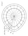
- Fig. 9 is a plan view showing the relationship between the present and marginal wheel diameters.
- Fig. 10 A is an explanatory chart for explaining a lift amount of a flat tappet relative to the rotational angle of a cam.
- Fig. 10B is an explanatory chart for explaining polar coordinate lift data.
- Fig. 10 C is an explanatory chart for explaining a method for obtaining profile data.
- Fig. 11 is an explanatory chart for explaining a method for obtaining the finished shape at the medium wheel diameter.
- Fig. 12 is a characteristic chart showing polar coordinate lift data calculated back to by using the profile data associated with the maximum wheel diameter and the respective wheel diameters.
- In the following, the embodiment of the present invention will be described with reference to the drawings.
- Fig. 1 is a block diagram showing a numerically controlled grinding machine, in which the
numeral 10 indicates a bed thereof, whereon a table 11 driven by aservo motor 16 viafeed screw mechanism 24 is disposed slidably in the direction of Z-axis. On the table 11, a head-stock 12 supporting aspindle 13 driven by aservo motor 14 is provided. On the right end of the table 11, atail stock 15 is mounted, and a cam shaft as a workpiece W is clamped between acenter 19 of thetail stock 15 and acenter 17 of thespindle 13. The workpiece W is engaged to a positioningpin 18 projected from thespindle 13 to be locked in a phase of rotation to the spindle. - On the rear portion of the
bed 10, awheel head 20 which is movable back and forth toward the workpiece W is guided and provided with a grinding wheel G driven by amotor 21. Thewheel head 20 is coupled to aservo motor 23 via afeed screw 25, and moved back and forth in the direction of X-axis by theservo motor 23 rotating forward or reverse. -
Drive units numerical controller 30 to drive theservo motors - The
numerical controller 30 mainly controls the rotation of the control axes numerically to control grinding of the workpiece W and dressing of the grinding wheel G. As shown in Fig. 2, thenumerical controller 30 mainly comprises amain CPU 31 for controlling the grinding machine, aROM 33 storing the control program and aRAM 32 for storing input data. - In the
RAM 32, a machining NCprofile data area 321 for storing the NC profile data and anNC program area 322 for storing the NC program for machining the workpiece, using the NC profile data stored in the NCprofile data area 321 are formed. - In addition, in the
numerical controller 30, adrive CPU 36, aRAM 35 and apulse distributing circuit 37 are as a driving system for theservo motors RAM 35 is a memory to which positioning data of the grinding wheel G, table 11 andspindle 13 are inputted from themain CPU 31. - The
drive CPU 36 executes the process of the slow-up, slow-down and interpolation to the target point with respect to the control axes, and outputs positioning data of the interpolation point periordically, and thepulse distributing circuit 37 outputs operation command pulses torespective drive units - The
numeral 70 designates an automatic programming apparatus connected to thenumerical controller 30 and automatically generating profile data Pi from the polar coordinate lift data L₀ and the wheel diameter Ri. - The
automatic programming apparatus 70 comprises afront CPU 71, aRAM 72 and an input-output interface 73. TheRAM 72 has alift data area 721 for storing the lift data of a plurality of workpieces, a polar coordinatelift data area 722 for storing the polar coordinate lift data L₀ converted from the lift data, amachining tolerance area 723 for storing a machining tolerance , a marginalwheel diameter area 724 for storing a marginal wheel diameter SRi upon which a renewal timing for the machining profile data is determined, aprofile data area 725 for storing the profile data corresponding to the marginal wheel diameter SRi, and a present wheel diametermemory data area 726 for storing the present wheel diameter Ri transferred from themain CPU 31 to thefront CPU 71 whenever the grinding wheel G is dressed at a predetermined cycle. - In the following, the operation of the present apparatus will be described.
- Fig. 3 shows a base routine program of the
front CPU 71 which judges commands inputted from akeyboard 44 and themain CPU 31, and branches to the various processing routines. - In
Step 200 of Fig. 3, whether a command instructing a generation of the profile data P₀ is given from the keyboard by the operator or not is determined. When the command for the profile data generation is given, processings shown in Fig. 4 are executed by thefront CPU 71. - First, in
Step 300, all flat tappet lift data necessary for machining are read from atape reader 42 via the input-output interface 73 and stored in thelift data area 721. Also, various data such as the workpiece number, minimum wheel diameter Rmin and maximum wheel diameter Rmax as the initial value of the wheel diameter are read viatape reader 42 and thekeyboard 44 and stored in a predetermined area in theRAM 72. Then, in thenext Step 301, the machining tolerance inputted from of thekeyboard 44 by the operator is read and stored in themachining tolerance area 723. - In
Step 302, the flat tappet lift data corresponding to the number of the workpiece to be machined which has been designated by the operator, is read from thelift data area 721 and converted into the polar coordinate lift data L₀, which is stored in the polar coordinatelift data area 722. As shown in Fig. 10A, the flat tappet lift data is represented by a moving amount, i.e., a lift amount of theflat tappet 3 which is, when thecam 1 is rotated, contacted with thecam 1 and movable in the direction of X-axis. Thus, if the rotational angle ϑ of thecam 1 is defined by the rotational angle of the reference point K on thebase circle 2, the lift amount Δ x (ϑ) is obtained as a function of ϑ. The lift data to be input is given, for example, in point sequence of the lift amount Δ x (ϑ) at every rotational angle of 0.5°. Since the contact position of theflat tappet 3 with thecam 1 varies responsive to the rotation of thecam 1, the lift data by the flat tappet is not given by the point sequence at every equicentral angle on the profile line of thecam 1. The flat tappet lift data, as shown in Fig. 10B, is converted into the polar coordinate lift data L₀ specifying the point sequence on the profile line of thecam 1 by the central angle ϑ and the length r(ϑ) of the radius vector with taking into account of the contact relation between theflat tappet 3 and thecam 1 as shown in Fig. 10A. - Then, the
CPU 31 moves its procedure to Step 303, wherein the profile data P₀ is calculated from the polar coordinate lift data L₀ and the maximum wheel diameter Rmax which is the initial wheel diameter. The profile data P₀ is obtained as shown in Fig. 10 C. First, the polar coordinate lift data L₀ is smoothly interpolated to obtain the lift data at discrete points H₁, H₂, ... Hn at every equicentral angle on the profile line of thecam 1. Then, a locus of the center M of circle C with radius Rmax (wheel diameter) contacting with the profile line A at the discrete points H₁, H₂, ... Hn is obtained, and the profile data P₀ indicating the relative feed amount of the grinding wheel at every equicentral angle is obtained from the distance between the center M and thecenter 0 of thecam 1. The profile data P₀ is stored in theprofile data area 725. Next, processings of thefront CPU 71 are moved to Step 304, wherein the profile data P₀ is stored, as the initial profile data, in the NCprofile data area 321 via themain CPU 31. - Then, in
Step 305, the marginal wheel diameters SR₁, SR₂, SR₃ are calculated and stored in a predetermined area in theRAM 72, and in thefollowing Step 306, the first marginal wheel diameter SR₁ is set in the marginalwheel diameter area 724 as the wheel diameter upon which the next renewal timing of the profile data is decided. - Calculating procedures of the marginal wheel diameter are particularly shown in Fig. 5.
- In
Step 400, the medium wheel diameter Rmid is calculated as a mean value between the minimum wheel diameter Rmin possible to grind at and the maximum wheel diameter Rmax as the initial value of the grinding wheel. Then, inStep 401, a polar coordinate lift data L₁ is calculated back from the profile data P₀ corresponding to the maximum wheel diameter Rmax and the medium wheel diameter Rmid. The polar coordinate lift data L₁ corresponds to the finished shape of the workpiece when the workpiece is ground with the grinding wheel of the medium wheel diameter Rmid using the profile data P₀. Next, inStep 402 , a polar coordinate lift data L₂ is calculated back from the profile data P₀ corresponding to the maximum wheel diameter Rmax and the minimum wheel diameter Rmin. The polar coordinate lift data L₂ corresponds to the finished shape of the workpiece when the workpiece is ground with the grinding wheel of the minimum wheel diameter Rmin using the profile data P₀. - The polar coordinate lift data L₁ is obtained as shown in Fig. 11. First, a locus of grinding wheel center decided by the profile data P₀ related to the maximum wheel diameter Rmax is defined as M, and a locus of point Si obtained by moving an arbitrary point Qi on the locus M toward the
spindle center 0 by the radial difference Δ R (=Rmax - Rmid) of the grinding wheel is defined as M₁. Then, point Ui spaced toward the spindle by the medium wheel diameter Rmid in the direction normal to the locus M₁ from the arbitrary point Si on the locus M₁ is obtained. A locus drawn by the point Ui is the finished shape from which the polar coordinate lift data L₁ is calculated. Similarly, for the minimum wheel diameter Rmin, the finished shape from which the polar coordinate lift data L₂ is calculated can be obtained in a same manner. The polar coordinate lift data L₀ corresponds to the maximum wheel diameter Rmax. Characteristics of these data L₀, L₁ and L₂ related to the cam rotational angle ϑ are shown in Fig. 12. It is recognized that deviation from the ideal finished shape corresponding to the polar coordidnate lift data L₀ is larger as the wheel diameter reduces. As the wheel diameter reduces, a phase advance in a area from the base circle to the top and phase lag in a area from the top to the base circle tend to increase. - Next, in
Step 403, a finished shape error ERR₁ is calculated from a maximum value of an absolute value of the difference between the polar coordinate lift data L₁(ϑ) and the polar coordinate lift data L₀(ϑ) with respect to the rotational angle of the cam. That is, the error ERR₁ is obtained from the following equation.
ERR₁ = Max.|L₁(ϑ) - L₀(ϑ)| - In a same manner, in
Step 404, a finished shape error ERR₂ is calculated from a maximum value of an absolute value of the difference between the polar coordinate lift data L₂(ϑ) and the polar coordinate lift data L₀(ϑ) by using following eauation.
ERR₂ = Max.|L₂(ϑ) - L₀(ϑ)| - Then, in
Step 405, as shown in Fig. 6, on a coordinate plan in which the finished shape error is plotted along y-axis and the wheel diameter along x-axis, a quadratic function y=f(x) passing three points of A (maximum wheel diameter Rmax, error 0), B (medium wheel diameter Rmid, error ERR₁) and C (minimum wheel diameter Rmin, error ERR₂) is calculated. - In
Step 406, then, the marginal diameters SR₁, SR₂ and SR₃ are calculated based upon the function y=f(x) and the machining tolerance ε . Namely, three preliminary wheel diameters PR₁ , PR₂ and PR₃ whereat the finished shape error reaches to ε, 2ε and 3ε, respectively, are first obtained. After that, wheel diameters, which are larger than the preliminary wheel diameter PR₁ , PR₂ and PR₃, respectively and coincide with the nearest ones of discrete wheel diameters with a distance of the dressing allowance D of the grinding wheel, are serched as the marginal diameters SR₁, SR₂ and SR₃. And each of the marginal wheel diameters is used for determining the renewal timing of the profile data used for machining. In such a manner, the marginal wheel diameters are obtained all together. - In the following, the operation of the
main CPU 31 at the time when machining command is input from an operatingpanel 45 will be described with reference to a flow-chart of Fig. 7. - In
Step 500, a workpiece W is ground in accordance with a NC program stored in theNC program area 322. That is, together with feeding of the grinding wheel G commanded by the NC program, profile data in the NCprofile data area 321 are commanded to be read, as a result, a cutting-in movement and a profile generating motion of the grinding wheel G are performed simultaneously and the workpiece is ground into a predetermined shape. - Then, the
CPU 31 moves its procedures to Step 501 to determine whether the grinding wheel G has been dressed during or after machining according to the NC program. When the dressing has been performed, innext Step 502, a new present wheel diameter Ri is obtained by subtracting the dressing allowance D from the present wheel diameter Ri. Then, inStep 503, the new present wheel diameter Ri is transferred to thefront CPU 71, and thereby stored in the present wheeldiameter data area 726. - Next, in
Step 504, the main CPU31 commands the front CPU71 to judge whether the machining error is within the tolerance ε if the workpiece W is machined with the grinding wheel having diameter Ri. - When the command is input into the front CPU71 by the main CPU31, it is determined YES in
Step 201 shown in Fig. 3, and thefront CPU 71 executes a program of Fig. 8. - In Fig. 8, in
Step 600, the present wheel diameter Ri transferred from themain CPU 31 and stored in the present wheeldiameter data area 726 is read. Then, inStep 601, it is determined whether the present wheel diameter Ri is not less than the marginal wheel diameter SRi (initially, the first marginal wheel diameter SRi is stored) stored in the marginalwheel diameter area 724. When it is YES, since the profile data is not necessary to be recalculated, the procedure is moved to Step 606 and a processing end signal is output to theCPU 31 to complete the program. - While, when it is determined NO in
Step 601, that is, when the present wheel diameter Ri becomes less than the marginal wheel diameter SRi, theCPU 31 moves its procedure to Step 602 to calculate the profile data Pi with the marginal wheel diameter SRi and the polar coordinate lift data L₀. Then, inStep 603, theprofile data area 725 is rewritten with the profile data newly calculated inStep 602. - In the succeeding
Step 604, new profile data Pi stored in theprofile data area 725 is transferred to themain CPU 31 via thefront CPU 71 and stored in the NCprofile data area 321. In thefollowing Step 605, the next marginal wheel diameter SRi+1 is stored in the marginalwheel diameter area 724. For example, when the marginal wheel diameter SRi to have been set is SR₁, the marginal wheel diameter SRi+1 to be set next becomes SR₂, and in thenext Step 606, the processing end signal is outputted to themain CPU 31 to complete the program. - In such a manner, whenever the present wheel diameter Ri reduces to the set marginal wheel diameter SRi (SR₁, SR₂, SR₃), the profile data Pi is newly calculated and the profile data used for machining is renewed into new profile data Pi which produces no machining errors.
- When the processing end signal is outputted to the
main CPU 31, processings of which are continued fromStep 505, of Fig. 7. InStep 505, it is determined whether new profile data Pi has been transferred. If it is determined YES, the procedure is moved tonext Step 506, wherein the transferred profile data Pi is stored in the NCprofile data area 321 to renew profile data used for machining. Then, inStep 507, it is determined whether all of the machining are completed, if the result is YES, the program is completed, and if the result is NO, processings of themain CPU 31 return again to theaforesaid Step 500. - In the description aforementioned, for the purpose of simplifying the description, though it has described that whenever the present wheel diameter Ri reduces to the set marginal wheel diameter SRi(SR₁, SR₂, SR₃), profile data corresponding to the marginal wheel diameter is recalculated, in practice, for example, while the workpiece is machined with the profile data P₀ corresponding to the maximum wheel diameter Rmax, the next profile data P₁ related to the first marginal wheel diameter SR₁ is calculated and stored in the
profile data area 725. Thus, when the present wheel diameter Ri has been become less than the marginal wheel diameter SR₁, the profile data used for machining are adapted to be renewed merely by transferring the profile data stored in theprofile data area 725 to the NCprofile data area 321. In such a manner, in practice, the recalculating time of the profile data is prevented from delaying the machining cycle time. - In the embodiment described above, when the marginal wheel diameter SR₁, SR₂, SR₃ are obtained, they are obtained all together by calculating the wheel diameters at which the finished shape errors are brought to multiples of the machining tolerance ε , from the quadratic function which approximates the relationship between the finished shape error and wheel diameter, passing through the three-point value of maximum finished shape errors to be caused if work-piece is machined with the grinding wheel having the maximum Rmax, medium Rmid and minimum Rmin wheel diameters, respectively, using the profile data P₀ corresponding to the maximum wheel diameter Rmax. However, for example, when the second marginal wheel diameter SR₂ is obtained, it may be obtained by calculating the wheel diameter at which the finished shape error is brought to the machining tolerance ε, from a quadratic function which approximates the relationship between the finished shape error and wheel diameter, passing through the three-point value of the finished shape errors to be caused if the workpiece is machined with the grinding wheel having the first marginal wheel diameter SR₁, medium wheel diameter Rmid and minimum wheel diameter Rmin, respectively, using the profile data P₁ related to the first marginal wheel diameter SR₁, by defining the mean value between the first marginal wheel diameter SR₁ and the minimum wheel diameter Rmin as the new medium wheel diameter Rmid.
- The third marginal wheel diameter SR₃ can also be obtained similarly. That is, when obtaining the next marginal wheel diameter, profile data presently used are used to obtain the finished shape errors.
- In such a manner, errors can be evaluated more accurately and the timing of renewal of the profile data can be more suitable.
- The method of interpolation of errors is not limited to quadratic functional interpolation aforementioned.
- As described heretofore, in the present invention, the workpiece can be machined without renewing the profile data for machining until the machining error becomes larger than a predetermined tolerance, so that the cycle time can be shortened on account of no wastefull recalculating of the profile data.
- Moreover, as the workpiece is machined within the machining tolerance, machining accuracy of the workpiece after machining can be kept constant within the tolerance.
- When machining cams with the same profile data, finished shape errors tend to increase as the diameter of a grinding wheel decreases. In order to keep the finished shape errors within a tolerance, the profile data used for machining must be renewed with new profile data corresponding to the present diameter of the grinding wheel. In the disclosed numerically controlled cam grinding machine, optimum wheel diameters, at which new profile data must be calculated, are decided automatically. The numerical controller calculates the marginal diameters which require renewal of profile data based upon the machining tolerance when a new grinding wheel is attached to the wheel head. After that, the numerical controller calculates new profile data from the marginal wheel diameter and lift data, when the present wheel diameter reaches into one of the marginal wheel diameters. The old profile data is renewed with the newly calculated profile data corresponding to the marginal wheel diameter.
Claims (3)
present wheel diameter memory means for storing the present wheel diameter of said grinding wheel,
machining tolerance input means for inputting a machining tolerance related the finished shape of said non-circular workpiece:
wheel diameter calculating means for calculating a marginal wheel diameter requiring renewal of the profile data based upon said machining tolerance;
profile data calculating means for calculating new profile data from said marginal wheel diameter and said lift data;
judging means for comparing said marginal wheel diameter and said present wheel diameter to judge whether said present wheel diameter is larger than said marginal wheel diameter or not; and
profile data renewing means for renewing the profile data used for machining, when said present wheel diameter reaches the marginal wheel diameter, with said new profile data corresponding to said marginal wheel diameter.
error calculating means for calculating a first finished shape error which is produced when said workpiece is ground with a grinding wheel having the minimum wheel diameter and profile data corresponding to the maximum wheel diameter, and a second finished shape error which is produced when said workpiece is ground with a grinding wheel having the medium wheel diameter between said maximum and minimum wheel diameters and said profile data corresponding to the maximum wheel diameter;
means for obtaining a quadratic function indicating the relationship between the finished shape error and the wheel diameter based upon said first and second finished shape errors corresponding to said medium and minimum wheel diameters;
means for calculating said marginal wheel diameter with the quadratic function and said machining tolerance.
Applications Claiming Priority (2)
| Application Number | Priority Date | Filing Date | Title |
|---|---|---|---|
| JP63186459A JPH0683945B2 (en) | 1988-07-26 | 1988-07-26 | Numerical controller for machining non-round workpieces |
| JP186459/88 | 1988-07-26 |
Publications (3)
| Publication Number | Publication Date |
|---|---|
| EP0352725A2 true EP0352725A2 (en) | 1990-01-31 |
| EP0352725A3 EP0352725A3 (en) | 1992-03-18 |
| EP0352725B1 EP0352725B1 (en) | 1995-02-15 |
Family
ID=16188832
Family Applications (1)
| Application Number | Title | Priority Date | Filing Date |
|---|---|---|---|
| EP89113680A Expired - Lifetime EP0352725B1 (en) | 1988-07-26 | 1989-07-25 | Numerical controller for machining a non-circular workpiece |
Country Status (4)
| Country | Link |
|---|---|
| US (1) | US5060164A (en) |
| EP (1) | EP0352725B1 (en) |
| JP (1) | JPH0683945B2 (en) |
| DE (1) | DE68921109T2 (en) |
Families Citing this family (17)
| Publication number | Priority date | Publication date | Assignee | Title |
|---|---|---|---|---|
| JPH0710482B2 (en) * | 1989-09-27 | 1995-02-08 | 豊田工機株式会社 | Non-circular creation device |
| JP3021156B2 (en) * | 1991-12-25 | 2000-03-15 | オークマ株式会社 | Machining error correction method for non-circular processing machine |
| JP2805119B2 (en) * | 1993-02-26 | 1998-09-30 | オークマ株式会社 | Numerical controller for processing non-circular workpieces |
| US5677855A (en) * | 1995-01-31 | 1997-10-14 | Smith & Nephew, Inc. | Method of generating grinding paths from a computer model for controlling a numerically controlled grinder |
| IL122770A0 (en) | 1997-12-25 | 1998-08-16 | Gotit Ltd | Automatic spray dispenser |
| US6242880B1 (en) | 1998-09-08 | 2001-06-05 | Cimplus, Inc. | Tolerance based motion control system |
| SG160423A1 (en) | 2005-03-23 | 2010-04-29 | Hurco Co Inc | Method of tolerance-based trajectory planning and control |
| DE102005050205A1 (en) * | 2005-10-20 | 2007-04-26 | Mtu Aero Engines Gmbh | Method and device for compensating position and shape deviations |
| DE102005050209A1 (en) * | 2005-10-20 | 2007-04-26 | Ott, Reinhold, Waterloo | Video signal feeding device for e.g. television set, has control unit for controlling video signal source depending on presence signal that is delivered by presence detect unit, which detects presence of person at area of feeding device |
| US7933677B2 (en) | 2006-08-04 | 2011-04-26 | Hurco Companies, Inc. | System and method for surface finish management |
| US8725283B2 (en) | 2006-08-04 | 2014-05-13 | Hurco Companies, Inc. | Generalized kinematics system |
| US8024068B2 (en) | 2006-08-04 | 2011-09-20 | Hurco Companies, Inc. | Machine tool control system |
| EP2049958B1 (en) | 2006-08-04 | 2012-09-19 | Hurco Companies Inc. | System and method for tool use management |
| US7797074B2 (en) * | 2007-03-01 | 2010-09-14 | Mori Seiki Usa, Inc. | Machine including grinding wheel and wheel dresser |
| US10639734B2 (en) * | 2014-12-17 | 2020-05-05 | Pratt & Whitney Canada Corp | System and method for automated machining of toothed members |
| US11402818B2 (en) * | 2016-12-12 | 2022-08-02 | Fanuc Corporation | Numerical controller and data structure |
| CN114536110B (en) * | 2022-03-03 | 2023-03-24 | 华辰精密装备(昆山)股份有限公司 | Error real-time compensation method for non-circular component complex contour grinding |
Citations (2)
| Publication number | Priority date | Publication date | Assignee | Title |
|---|---|---|---|---|
| FR2340572A1 (en) * | 1976-02-09 | 1977-09-02 | Cone Blanchard Machine Cy | Computer controlled profile machining tool - is for machining cylinders of wankel engines and has cutter which moves relative to workpiece |
| US4061952A (en) * | 1975-04-14 | 1977-12-06 | Cranfield Institute Of Technology | Computer-controlled machine tool |
Family Cites Families (19)
| Publication number | Priority date | Publication date | Assignee | Title |
|---|---|---|---|---|
| GB1062818A (en) * | 1963-08-09 | 1967-03-22 | Toyo Kogyo Kabushiki Kaisha | Rotating type cam grinding machine |
| US3482357A (en) * | 1965-10-27 | 1969-12-09 | Fujitsu Ltd | Automatically controlled cam grinding system |
| US3917930A (en) * | 1974-11-25 | 1975-11-04 | Cincinnati Milacron Inc | Method and apparatus for adaptively positioning a machine element |
| US4084243A (en) * | 1975-05-19 | 1978-04-11 | Oki Electric Industry Co., Ltd. | Cutter radius compensation system |
| JPS52133198A (en) * | 1976-04-30 | 1977-11-08 | Toyoda Mach Works Ltd | Control method of cam |
| JPS52144895A (en) * | 1976-05-27 | 1977-12-02 | Toyoda Mach Works Ltd | Control method for cam machining apparatus |
| DE2810646A1 (en) * | 1977-03-18 | 1978-09-21 | Komatsu Mfg Co Ltd | NUMERICAL CONTROL SYSTEM FOR A MACHINE TOOL |
| JPS5467280A (en) * | 1977-11-08 | 1979-05-30 | Toyoda Mach Works Ltd | Numerical control unit for controlling the processing of a nonround work |
| JPS5518383A (en) * | 1978-07-28 | 1980-02-08 | Toyoda Mach Works Ltd | Numerical controller for controlling grinding |
| JPS58126065A (en) * | 1982-01-21 | 1983-07-27 | Toyoda Mach Works Ltd | Grindstone wheel feeding device in grinder |
| JPS58192750A (en) * | 1982-05-03 | 1983-11-10 | Toyoda Mach Works Ltd | Grinding machine |
| JPS591164A (en) * | 1982-06-23 | 1984-01-06 | Toyoda Mach Works Ltd | Numerically controlled grinder |
| JPS6294247A (en) * | 1985-10-17 | 1987-04-30 | Toyoda Mach Works Ltd | Numerically controlled machine tool having halfway stopping function |
| JPH0698554B2 (en) * | 1986-09-22 | 1994-12-07 | 豊田工機株式会社 | Numerical control processing equipment |
| JPS6384845A (en) * | 1986-09-24 | 1988-04-15 | Toyoda Mach Works Ltd | Method of machining non-true circular workpiece |
| US4751647A (en) * | 1986-09-25 | 1988-06-14 | Bryant Grinder Corporation | Method for determining tool size and for machining |
| US4791575A (en) * | 1986-10-31 | 1988-12-13 | The Pratt & Whitney Company, Inc. | Method for generating axis control data for use in controlling a grinding machine and the like and system therefor |
| JPH0652484B2 (en) * | 1988-02-15 | 1994-07-06 | 豊田工機株式会社 | Numerical controller for machining non-round workpieces |
| JPH0669663B2 (en) * | 1988-03-15 | 1994-09-07 | 豊田工機株式会社 | Numerical control grinder |
-
1988
- 1988-07-26 JP JP63186459A patent/JPH0683945B2/en not_active Expired - Lifetime
-
1989
- 1989-07-24 US US07/383,528 patent/US5060164A/en not_active Expired - Fee Related
- 1989-07-25 DE DE68921109T patent/DE68921109T2/en not_active Expired - Fee Related
- 1989-07-25 EP EP89113680A patent/EP0352725B1/en not_active Expired - Lifetime
Patent Citations (2)
| Publication number | Priority date | Publication date | Assignee | Title |
|---|---|---|---|---|
| US4061952A (en) * | 1975-04-14 | 1977-12-06 | Cranfield Institute Of Technology | Computer-controlled machine tool |
| FR2340572A1 (en) * | 1976-02-09 | 1977-09-02 | Cone Blanchard Machine Cy | Computer controlled profile machining tool - is for machining cylinders of wankel engines and has cutter which moves relative to workpiece |
Also Published As
| Publication number | Publication date |
|---|---|
| DE68921109T2 (en) | 1995-07-06 |
| JPH0236047A (en) | 1990-02-06 |
| EP0352725A3 (en) | 1992-03-18 |
| US5060164A (en) | 1991-10-22 |
| JPH0683945B2 (en) | 1994-10-26 |
| EP0352725B1 (en) | 1995-02-15 |
| DE68921109D1 (en) | 1995-03-23 |
Similar Documents
| Publication | Publication Date | Title |
|---|---|---|
| EP0352725B1 (en) | Numerical controller for machining a non-circular workpiece | |
| KR970005561B1 (en) | Numerical control apparatus for machining non-circular workpieces | |
| EP0465511B1 (en) | Dynamic correction of servo following errors in a computer-numerically-controlled system and fixed cycle utilizing same | |
| US4967515A (en) | Numerically controlled grinding machine | |
| US4484413A (en) | Control apparatus for a grinding machine | |
| US4570386A (en) | Regulating wheel dressing system in centerless grinder | |
| US5031107A (en) | Numerical control apparatus for machining non-circular workpieces | |
| US4757457A (en) | Numerical control method and apparatus with feedrate difference | |
| US4902951A (en) | Numerically controlled machine tool | |
| WO1991012111A1 (en) | Computer-controlled grinding machine for producing objects with complex shapes | |
| EP0098970A2 (en) | Numerical controller for a grinding machine | |
| US5289660A (en) | Method and apparatus for grinding non-circular workpiece | |
| US5746643A (en) | Method of grinding and machining non-circular workpiece and apparatus for the same | |
| US4740902A (en) | Numerical control apparatus having memory storage for machine patterns, plural individually selectable remachining patterns, and control parameters | |
| JP3286689B2 (en) | Processing device and processing method | |
| JP3543459B2 (en) | Numerical control device for machining workpieces | |
| JP2669641B2 (en) | Numerical controller for machining non-round workpieces | |
| JP2604003B2 (en) | Numerical controller for machining non-round workpieces | |
| JPH10268921A (en) | Data preparing device for non-round work machining and numerical controller | |
| JP2640653B2 (en) | Manual synchronous feed mechanism for numerically controlled machine tools | |
| JP2940975B2 (en) | Numerically controlled grinding machine | |
| JPH0760338B2 (en) | Numerical controller for machining non-round workpieces | |
| JPS6384865A (en) | Numerically controlled grinding machine | |
| JPS6378202A (en) | Numerical controller for machining non real circular work | |
| JPS63106809A (en) | Numerical control machine tool |
Legal Events
| Date | Code | Title | Description |
|---|---|---|---|
| PUAI | Public reference made under article 153(3) epc to a published international application that has entered the european phase |
Free format text: ORIGINAL CODE: 0009012 |
|
| AK | Designated contracting states |
Kind code of ref document: A2 Designated state(s): DE FR GB |
|
| PUAL | Search report despatched |
Free format text: ORIGINAL CODE: 0009013 |
|
| AK | Designated contracting states |
Kind code of ref document: A3 Designated state(s): DE FR GB |
|
| 17P | Request for examination filed |
Effective date: 19920529 |
|
| 17Q | First examination report despatched |
Effective date: 19940414 |
|
| GRAA | (expected) grant |
Free format text: ORIGINAL CODE: 0009210 |
|
| AK | Designated contracting states |
Kind code of ref document: B1 Designated state(s): DE FR GB |
|
| REF | Corresponds to: |
Ref document number: 68921109 Country of ref document: DE Date of ref document: 19950323 |
|
| ET | Fr: translation filed | ||
| PGFP | Annual fee paid to national office [announced via postgrant information from national office to epo] |
Ref country code: FR Payment date: 19950711 Year of fee payment: 7 |
|
| PGFP | Annual fee paid to national office [announced via postgrant information from national office to epo] |
Ref country code: GB Payment date: 19950714 Year of fee payment: 7 |
|
| PGFP | Annual fee paid to national office [announced via postgrant information from national office to epo] |
Ref country code: DE Payment date: 19950725 Year of fee payment: 7 |
|
| PLBE | No opposition filed within time limit |
Free format text: ORIGINAL CODE: 0009261 |
|
| STAA | Information on the status of an ep patent application or granted ep patent |
Free format text: STATUS: NO OPPOSITION FILED WITHIN TIME LIMIT |
|
| 26N | No opposition filed | ||
| PG25 | Lapsed in a contracting state [announced via postgrant information from national office to epo] |
Ref country code: GB Effective date: 19960725 |
|
| GBPC | Gb: european patent ceased through non-payment of renewal fee |
Effective date: 19960725 |
|
| PG25 | Lapsed in a contracting state [announced via postgrant information from national office to epo] |
Ref country code: FR Effective date: 19970328 |
|
| PG25 | Lapsed in a contracting state [announced via postgrant information from national office to epo] |
Ref country code: DE Effective date: 19970402 |
|
| REG | Reference to a national code |
Ref country code: FR Ref legal event code: ST |