EP0353100A2 - Two-piece flat-top container - Google Patents
Two-piece flat-top container Download PDFInfo
- Publication number
- EP0353100A2 EP0353100A2 EP89307722A EP89307722A EP0353100A2 EP 0353100 A2 EP0353100 A2 EP 0353100A2 EP 89307722 A EP89307722 A EP 89307722A EP 89307722 A EP89307722 A EP 89307722A EP 0353100 A2 EP0353100 A2 EP 0353100A2
- Authority
- EP
- European Patent Office
- Prior art keywords
- panels
- edge
- fold
- container
- panel
- Prior art date
- Legal status (The legal status is an assumption and is not a legal conclusion. Google has not performed a legal analysis and makes no representation as to the accuracy of the status listed.)
- Withdrawn
Links
Images


Classifications
-
- B—PERFORMING OPERATIONS; TRANSPORTING
- B65—CONVEYING; PACKING; STORING; HANDLING THIN OR FILAMENTARY MATERIAL
- B65D—CONTAINERS FOR STORAGE OR TRANSPORT OF ARTICLES OR MATERIALS, e.g. BAGS, BARRELS, BOTTLES, BOXES, CANS, CARTONS, CRATES, DRUMS, JARS, TANKS, HOPPERS, FORWARDING CONTAINERS; ACCESSORIES, CLOSURES, OR FITTINGS THEREFOR; PACKAGING ELEMENTS; PACKAGES
- B65D5/00—Rigid or semi-rigid containers of polygonal cross-section, e.g. boxes, cartons or trays, formed by folding or erecting one or more blanks made of paper
- B65D5/40—Rigid or semi-rigid containers of polygonal cross-section, e.g. boxes, cartons or trays, formed by folding or erecting one or more blanks made of paper specially constructed to contain liquids
-
- B—PERFORMING OPERATIONS; TRANSPORTING
- B65—CONVEYING; PACKING; STORING; HANDLING THIN OR FILAMENTARY MATERIAL
- B65D—CONTAINERS FOR STORAGE OR TRANSPORT OF ARTICLES OR MATERIALS, e.g. BAGS, BARRELS, BOTTLES, BOXES, CANS, CARTONS, CRATES, DRUMS, JARS, TANKS, HOPPERS, FORWARDING CONTAINERS; ACCESSORIES, CLOSURES, OR FITTINGS THEREFOR; PACKAGING ELEMENTS; PACKAGES
- B65D5/00—Rigid or semi-rigid containers of polygonal cross-section, e.g. boxes, cartons or trays, formed by folding or erecting one or more blanks made of paper
- B65D5/42—Details of containers or of foldable or erectable container blanks
- B65D5/54—Lines of weakness to facilitate opening of container or dividing it into separate parts by cutting or tearing
-
- B—PERFORMING OPERATIONS; TRANSPORTING
- B65—CONVEYING; PACKING; STORING; HANDLING THIN OR FILAMENTARY MATERIAL
- B65D—CONTAINERS FOR STORAGE OR TRANSPORT OF ARTICLES OR MATERIALS, e.g. BAGS, BARRELS, BOTTLES, BOXES, CANS, CARTONS, CRATES, DRUMS, JARS, TANKS, HOPPERS, FORWARDING CONTAINERS; ACCESSORIES, CLOSURES, OR FITTINGS THEREFOR; PACKAGING ELEMENTS; PACKAGES
- B65D5/00—Rigid or semi-rigid containers of polygonal cross-section, e.g. boxes, cartons or trays, formed by folding or erecting one or more blanks made of paper
- B65D5/42—Details of containers or of foldable or erectable container blanks
- B65D5/70—Break-in flaps, or members adapted to be torn-off, to provide pouring openings
- B65D5/706—Tearable flaps defined by score-lines or incisions provided in a separate end closure of a tubular container
Definitions
- This invention relates generally to thermoplastic coated paperboard containers and, more particularly, to a blank and a container including a separate top end closure of an improved construction.
- Containers for beverages such as milk, cream, other dairy products, juices, and the like, are conventionally constructed from the thermoplastic coated paperboard.
- these containers include a top end closure with a folded roof structure adaptable to providing a readily available pouring spout when the contents of the container are to be dispensed.
- Coated paperboard blanks for constructing such a container are made on converting machines similar to those disclosed by Monroe et al Patent No. 2,682,208 and Earp Patent No. 3,731,600. After construction, the blanks are processed by forming, filling and sealing machines, such as those disclosed by Monroe et al Patent No. 3,303,761, Allen Patent No. 3,918,236, Egleston patent No. 3,398,659 or Young Patent No. 4,193,833, to produce the formed, filled and sealed containers of the type referred to above and shown and described in Egleston et al Patent No. 3,270,940, or Lisiecki Patent No. 4,422,570.
- a general object of the invention is to provide a thermoplastic coated paperboard container including improved top closure means for providing the above mentioned desirable fully openable feature for particular products.
- Another object of the invention is to provide an improved thermoplastic coated paperboard container suitable for being filled with a juice concentrate and then frozen, or with foodstuffs of a somewhat solid consistency.
- a further object of the invention is to provide a square or rectangular paperboard container including an improved, conveniently fully openable flat top closure arrangement.
- a still further object of the invention is to provide a flat top container including lift flaps having a perforated portion covered with a foil patch, a thermoplastic film, or a thermoplastic hot melt.
- the perforated portion may be "sandwiched" between two liquid proof films.
- Still another object of the invention is to provide alternate embodiments of a flat top container wherein the cover panel is one of a full panel top for maximum "billboard" effect.
- Still another object of the invention is to provide a separate top cover with provisions for overlapping out-turned lift tabs formed on the container proper.
- thermoplastic coated two-piece container comprising:
- thermoplastic coated two-piece container comprising:
- a thermplastic coated two-piece container comprising:
- thermoplastic coated container comprising:
- Figure 1 illustrates a container blank 10 formed in accordance with the principles of the present invention.
- the container blank 10 is generally divided into three sections including a top fold-over portion 12, a body portion 14, and a conventional flat bottom end closure 16.
- the latter may be any suitable end closure arrangement and is not a part of this invention.
- the body portion 14 comprises a plurality of integrally connected body panels, namely, three full width panels 18, 20 and 22, and a two-partial width panels 24 and 26 connected to the panels 18 and 22, respectively.
- the container blank 10 is defined on its longitudinal sides by edges 28 and 30.
- the body panels 24/18, 18/20, 20/22 and 22/26 are connected by vertical score lines 32, 34, 36 and 38. It should be apparent that the body panels may be equal in width and hence, adaptable to forming a square cross-section container, or may be formed such that one pair of alternate body panels is wider than the other pair and, hence, adaptable to forming a rectangular cross-section container.
- the top fold-over portion 12 comprises three panel segments 40, 42 and 44 connected by perforated lines 46, 48 and 50 to the tops of the body panels 18, 20 and 22. Edge panels 52 and 54 are connected by perforated lines 56 and 58, respectively, to the tops of the partial width panels 24 and 26.
- a layer 68 of a suitable material such as a thermoplastic hot melt, or a strip of either aluminum foil or thermoplastic film, is secured to all the inside surfaces adjacent the perforated lines 56, 46, 48, 50 and 58.
- a suitable material such as a thermoplastic hot melt, or a strip of either aluminum foil or thermoplastic film.
- the perforated lines may be formed in the paperboard layer only, and then covered by the conventional outer and inner polyethylene films.
- FIG. 3 there is illustrated a separate top end cover 70 including a central portion 72 with four side segments 74, 76, 78 and 80 connected thereto by respective score lines 82, 84, 86, and 88.
- Small triangular segment pairs 90/92, 94/96, 98/100 and 102/104 are formed between the side segments 79/76, 76/78, 78/80 and 80/74, respectively, connected thereto be extensions of the score lines 82, 84, 86 and 88.
- the triangular segment pairs 90/92, 94/96, 98/100 and 102/104 are either formed as one continuous triangle, or, alternatively, connected to each other by score lines 106, 108, 110 and 112, respectively.
- the container blank 10 illustrated in Figure 1 is first formed into a side seamed blank as shown in Figure 2 by rotating the body panels 22 and 26 as a unit about the vertical score line 36, and having the inside surfaces of the body panel 22 come into contact with the inside surface of the body panel 20, with the vertical score line 38 positioned next to the vertical score line 34, and with the inside surface of the panel 26 contacting the inside surface of the body panel 18 adjacent the vertical score line 34.
- the body panel 24 is then rotated about the vertical score line 32 to bring its inside surface into contact with the inside surface of the body panel 18, and overlapping the outside surface of the panel 26.
- the various members of a bottom end closure will make similar movements.
- the edge panel 44 overlies the edge panel 42
- the edge panel 54 overlies a portion of the edge panel 40
- the edge panel 52 overlies the edge panels 40.
- the container blank 10 is then sealed where the inside area of the body panel 24 comes into contact with the outside surfaces of the panel 26.
- the fold-over segment 54 is narrower than the segment 52, such that they abut against each other, but do not overlap.
- the panel 26 could be sealed to the outside surface of the panel 24, rather than to the inner surface thereof as described above.
- the blank may be formed as shown at 10′ in Figure 1A, wherein there are four full body panels, panel 24′ being a full width panel, rather than the partial width panel 24 of Figure 1, and panel 26′ being a side seam flap for conventional corner lapping, rather than the partial width center lapping panel 26 of Figure 1.
- the panel segment 54 of Figure 1 is eliminated and a full width panel segment 52′ replaces the partial width segment 52 of Figure 1.
- the edge panels 40, 42, 44 and 52/54 are forced outwardly and downwardly about the respective perforated lines 46, 48, 50 and 56/58, after which the end cover 70 is placed on the edges formed by the perforated lines, followed by the bending of the side segments 74, 76, 78 and 80 about the score lines 82, 84, 86 and 88 onto the panel segments 40, 42, 44 and 52/54.
- edge panels 40, 42, 44, 52 and 54 may be folded about the respective perforated lines 46, 48, 50, 66 and 58 onto the respective body panels 18, 20, 22, 24 and 26 while the blank 10 is still in its flat state shown in Figure 1. This operation would then be followed by the formation of the side seamed blank of Figure 2.
- FIG. 4 illustrates the top end closure 12 structure once the sealing thereof has been effected.
- FIGs. 8-14 there is illustrated an alternate embodiment wherein the body portion 14 and bottom closure 16 are the same as for the Figs. 1-7 arrangement, but wherein the panel segments 40, 42, 44 and 52/54 are replaced by two adjacent partial segments 114 and 116.
- the latter segments are connected by perforated lines 118 and 120, respectively, to adjacent body panels 18 and 20.
- the segments 114 and 116 are separated from each other by a weakened line 122.
- a separate top end cover 124 includes a central portion 126, with four side segments 128, 130, 132 and 134 connected thereto by respective score lines 136, 138, 140 and 142.
- Small triangular segment pairs 144/146, 148/150, 152/154 and 156/158 are formed between the side segments 128/130, 130/132, 132/134 and 134/128, respectively, connected thereto by extensions of the score lines 136, 138, 140 and 142.
- the triangular segment pairs 144/146, 148/150, 152/154 and 156/158 may be connected to each other by score lines 160, 162, 164 and 166, respectively.
- a score line 168 extends from the approximate midpoint of the score line 136 to the approximate midpoint of the score line 138.
- a first perforated line 170 extends from the approximate midpoint of the score line 140 to the juncture of the score lines 138 and 168.
- a second perforated line 172 extends from the approximate midpoint of the score line 142 to the juncture of the score lines 136 and 168.
- a further perforated line 174 is formed across the width of the side segment 132 from the juncture of the score line 140 and the perforated line 170.
- a similar perforated line 176 is formed across the width of the side segment 134 from the juncture of the score line 142 and the perforated line 172.
- the container blank illustrated in Figure 8 is formed into the side seamed blank shown in Figure 9 in the same manner as the blank 10 of Figure 1 is formed into the side seamed blank of Figure 2. Thereafter, the side seamed blank is opened up into a squared condition and the panel segments 114 and 116 are folded outwardly and downwardly onto the body panels 18 and 20, respectively, as shown in Figure 11. The end cover 124 is then placed on the edges formed by the perforated lines 118 and 120, as well as on the co-planar free upper edges 178, 180, 182, 184 and 186 of the respective body panels 18, 20, 22, 24 and 26, as may be noted from Figure 11.
- the folded-over segments 114 and 116 serve as lift tabs, causing adjacent halves of the side segments 132 and 134 to break at the perforated lines 174 and 176, respectively, as shown in Figure 13. Thereafter, further lifting of the lift tabs 114 and 116 causes the central portion 126 to tear along the perforated lines 170 and 172, terminating at the score line 168, serving as a hinge as shown in Figure 14.
- thermoplastic coated paperboard carton which is ideally suited for being filled with a frozen concentrate, such as orange juice, or with a spoonable product, such as yogurt and puddings, for example, and sealed for distribution through the marketing system, and capable of being readily and easily opened by the consumer.
Abstract
A flat-top, thermoplastic - coated, paperboard container includes a separate cover panel (70) and fold-out segments (40,42) having weakened lines (46,48,50,56,58) formed thereon such that the top may be opened by using the fold-out segments (40,42) as lift tabs and breaking the weakened line (48) at the front and progressively breaking the weakened lines (46,50) along the sides upon peeling back the fold-out segments (40,42) and the cover panel (70), to provide access to the contents. Provisions are included for protecting the weakened lines (46,48,50,56,58) to prevent leakage.
Description
- This invention relates generally to thermoplastic coated paperboard containers and, more particularly, to a blank and a container including a separate top end closure of an improved construction.
- Containers for beverages such as milk, cream, other dairy products, juices, and the like, are conventionally constructed from the thermoplastic coated paperboard. Typically, these containers include a top end closure with a folded roof structure adaptable to providing a readily available pouring spout when the contents of the container are to be dispensed.
- Coated paperboard blanks for constructing such a container are made on converting machines similar to those disclosed by Monroe et al Patent No. 2,682,208 and Earp Patent No. 3,731,600. After construction, the blanks are processed by forming, filling and sealing machines, such as those disclosed by Monroe et al Patent No. 3,303,761, Allen Patent No. 3,918,236, Egleston patent No. 3,398,659 or Young Patent No. 4,193,833, to produce the formed, filled and sealed containers of the type referred to above and shown and described in Egleston et al Patent No. 3,270,940, or Lisiecki Patent No. 4,422,570.
- While this type of container has been generally satisfactory for liquid products, it is desirable to utilize a similar square or rectangular thermoplastic coated paperboard container for frozen juices with a modified top closure arrangement which is adaptable to being fully opened, in lieu of using a conventional cylindrical paperboard container with a removable metal or solid plastic top cover. Such a modified top closure arrangement is desirable also for containing and providing access to "spoonable" products, such as yogurt and puddings. One example of a satisfactory top closure of a substantially fully openable type is shown and described in Lisiecki Patent No. 4,397,415. A further example of a satisfactory to closure of a completely fully openable type is shown and described in Lisiecki U.S. Patent No. 4,702,407.
- A general object of the invention is to provide a thermoplastic coated paperboard container including improved top closure means for providing the above mentioned desirable fully openable feature for particular products.
- Another object of the invention is to provide an improved thermoplastic coated paperboard container suitable for being filled with a juice concentrate and then frozen, or with foodstuffs of a somewhat solid consistency.
- A further object of the invention is to provide a square or rectangular paperboard container including an improved, conveniently fully openable flat top closure arrangement.
- A still further object of the invention is to provide a flat top container including lift flaps having a perforated portion covered with a foil patch, a thermoplastic film, or a thermoplastic hot melt. Alternately, the perforated portion may be "sandwiched" between two liquid proof films.
- Still another object of the invention is to provide alternate embodiments of a flat top container wherein the cover panel is one of a full panel top for maximum "billboard" effect.
- Still another object of the invention is to provide a separate top cover with provisions for overlapping out-turned lift tabs formed on the container proper.
- According to one aspect of the present invention, there is provided a thermoplastic coated two-piece container comprising:
- (a) four body panels;
- (b) a plurality of top fold-down edge panels integrally connected to the top ends of selected body panels and folded outwardly and downwardly onto said selected body panels to serve as lift tabs;
- (c) a separate top cover panel mounted on the top ends of said body panels and including a central portion and four side edge fold-down panel segments folded onto and sealed to the underlying panel surfaces;
- (d) a plurality of weakened lines formed on said plurality of top fold-down edge panels where connected to said body panels and adapted to be broken upon upward pulling of said lift tabs.
- According to a second aspect of the present invention, there is provided a thermoplastic coated two-piece container comprising:
- (a) four body panels;
- (b) four top fold-down edge panels connected by weakened lines to said four body panels, and folded outwardly and downwardly onto said four body panels to serve as lift tabs; and
- (c) a separate top cover panel mounted on the weakened lines and including a central portion and four side edge fold-down panel segments folded onto and sealed to said four top fold-down edge panels.
- According to a third aspect of the present invention, there is provided a thermplastic coated two-piece container comprising:
- (a) four body panels;
characterized in that said container further comprises: - (b) two top fold-down edge panels connected by weakened lines to adjacent portions of two of said four body panels and folded outwardly and downwardly onto said two body panels; and
- (c) a separate top cover mounted on the two weakened lines and the remaining top edges of said four body panels, and including a central portion and four side edge fold-down panel segments folded onto and sealed to said two top fold-down edge panels and to the remaining exposed top edge portions of said four body panels.
- According to a fourth aspect of the present invention, there is provided a thermoplastic coated container comprising:
- (a) body panel means arranged in a ring about a substantially vertical axis for encircling contents of said container,
characterized in that the container further comprises: - (b) top fold-down edge panel means integrally connected to the upper extremity of said body panel means and extending outwardly and downwardly relative to said body panel means to serve as lift tab means, and
- (c) a top cover mounted on said upper extremity and including a central panel and side fold-down panel means extending downwardly and outwardly relative to said top fold-down edge panel means and sealed thereto.
- In order that the invention may be clearly understood and readily carried into effect, by way of example reference is now made to the following drawings and related description.
-
- Figure 1 is a plan view of the inside surface of a coated paperboard container blank used to construct a container having a top end closure in accordance with the present invention;
- Figure 1A is a fragmentary plan view of an alternate embodiment of the Figure 1 structure.
- Figure 2 is a plan view of the outside surface of a blank after it is side seamed from the blank illustrated in Figure 1;
- Figure 3 is a top view of a separate top cover for the container formed from the Figures 1 and 2 blank;
- Figures 4 and 5 are enlarged fragmentary perspective views illustrating sequentially the steps involved in forming the flat top end closure;
- Figures 6 and 7 are a fragmentary perspective views showing the container of Figure 5 after the top closure has been sealed closed and then opened;
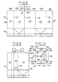
- Figure 8 is a fragmentary layout view of the inside surface of an alternate embodiment blank from which a container embodying the invention may be erected;
- Figures 9 and 10 are views of the alternate embodiment comparable to the Figures 2 and 3 of the preferred embodiment; and
- Figures 11-14 are views of the alternate embodiment comparable to the Figures 4-7 of the preferred embodiment.
- Referring now to the drawings in greater detail, Figure 1 illustrates a container blank 10 formed in accordance with the principles of the present invention. The container blank 10 is generally divided into three sections including a top fold-over
portion 12, abody portion 14, and a conventional flat bottom end closure 16. The latter may be any suitable end closure arrangement and is not a part of this invention. - The
body portion 14 comprises a plurality of integrally connected body panels, namely, threefull width panels partial width panels panels edges body panels 24/18, 18/20, 20/22 and 22/26 are connected byvertical score lines - The top fold-over
portion 12 comprises threepanel segments perforated lines body panels Edge panels perforated lines partial width panels - A
layer 68 of a suitable material, such as a thermoplastic hot melt, or a strip of either aluminum foil or thermoplastic film, is secured to all the inside surfaces adjacent theperforated lines - Referring now to Figure 3, there is illustrated a separate
top end cover 70 including acentral portion 72 with fourside segments respective score lines score lines - The container blank 10 illustrated in Figure 1 is first formed into a side seamed blank as shown in Figure 2 by rotating the
body panels vertical score line 36, and having the inside surfaces of thebody panel 22 come into contact with the inside surface of thebody panel 20, with thevertical score line 38 positioned next to thevertical score line 34, and with the inside surface of thepanel 26 contacting the inside surface of thebody panel 18 adjacent thevertical score line 34. Thebody panel 24 is then rotated about thevertical score line 32 to bring its inside surface into contact with the inside surface of thebody panel 18, and overlapping the outside surface of thepanel 26. The various members of a bottom end closure will make similar movements. Insofar as the top fold-overportion 12 is concerned, theedge panel 44 overlies theedge panel 42, theedge panel 54 overlies a portion of theedge panel 40, and theedge panel 52 overlies theedge panels 40. The container blank 10 is then sealed where the inside area of thebody panel 24 comes into contact with the outside surfaces of thepanel 26. Note that the fold-oversegment 54 is narrower than thesegment 52, such that they abut against each other, but do not overlap. - In the Figure 1 structure, if desired, in the formation of the side seam blank the
panel 26 could be sealed to the outside surface of thepanel 24, rather than to the inner surface thereof as described above. Additionally, if desired, the blank may be formed as shown at 10′ in Figure 1A, wherein there are four full body panels,panel 24′ being a full width panel, rather than thepartial width panel 24 of Figure 1, andpanel 26′ being a side seam flap for conventional corner lapping, rather than the partial widthcenter lapping panel 26 of Figure 1. Thepanel segment 54 of Figure 1 is eliminated and a fullwidth panel segment 52′ replaces thepartial width segment 52 of Figure 1. - Accordingly, after the side seam blank is opened up into a squared condition, as shown in Figure 4, the
edge panels perforated lines end cover 70 is placed on the edges formed by the perforated lines, followed by the bending of theside segments panel segments - If desired, the
edge panels perforated lines respective body panels - The sealing of the interrelated elements of the top fold-over portions is then accomplished by conventional means, such as a sonic or high frequency vibration sealing means. The sealing of the various top end closure elements may also be accomplished by other means, such as gas heat, if desired. Figure 4 illustrates the
top end closure 12 structure once the sealing thereof has been effected. - In opening the carton, three
panel segments side segments tabs lines - Referring now to Figs. 8-14, there is illustrated an alternate embodiment wherein the
body portion 14 and bottom closure 16 are the same as for the Figs. 1-7 arrangement, but wherein thepanel segments partial segments perforated lines adjacent body panels segments line 122. - A separate
top end cover 124 includes acentral portion 126, with fourside segments respective score lines side segments 128/130, 130/132, 132/134 and 134/128, respectively, connected thereto by extensions of the score lines 136, 138, 140 and 142. The triangular segment pairs 144/146, 148/150, 152/154 and 156/158 may be connected to each other byscore lines - A
score line 168 extends from the approximate midpoint of thescore line 136 to the approximate midpoint of thescore line 138. A firstperforated line 170 extends from the approximate midpoint of thescore line 140 to the juncture of thescore lines perforated line 172 extends from the approximate midpoint of thescore line 142 to the juncture of thescore lines perforated line 174 is formed across the width of theside segment 132 from the juncture of thescore line 140 and theperforated line 170. A similarperforated line 176 is formed across the width of theside segment 134 from the juncture of thescore line 142 and theperforated line 172. - The container blank illustrated in Figure 8 is formed into the side seamed blank shown in Figure 9 in the same manner as the blank 10 of Figure 1 is formed into the side seamed blank of Figure 2. Thereafter, the side seamed blank is opened up into a squared condition and the
panel segments body panels end cover 124 is then placed on the edges formed by theperforated lines upper edges respective body panels - Once the
end cover 124 is so placed, itsside segments segments body panels segments segments body panels 18 and 20 (Figure 12), whereupon they are sealed by conventional means. - In opening the carton, the folded-over
segments side segments perforated lines lift tabs central portion 126 to tear along theperforated lines score line 168, serving as a hinge as shown in Figure 14. - It should be apparent that the invention provides a novel and efficient thermoplastic coated paperboard carton which is ideally suited for being filled with a frozen concentrate, such as orange juice, or with a spoonable product, such as yogurt and puddings, for example, and sealed for distribution through the marketing system, and capable of being readily and easily opened by the consumer.
- It is believed to be important to note that if the
perforated lines layer 68 from the blank of Figure 1. Furthermore, in lieu of theperforated lines extra layer 68 described above. - While two embodiments of the invention have been shown and described, other modifications thereof are possible within the scope of the following claims.
Claims (16)
1. A thermoplastic coated two-piece container comprising:
(a) four body panels (18-26);
(b) a plurality of top fold-down edge panels (40,42,44,52,54;114,116) integrally connected to the top ends of selected body panels (18-26) and folded outwardly and downwardly onto said selected body panels (18-26) to serve as lift tabs (40,42,44;114,116);
(c) a separate top cover panel (70;124) mounted on the top ends of said body panels (18-26) and including a central portion (72,126) and four side edge fold-down panel segments (74-80;128-134) folded onto and sealed to the underlying panel surfaces;
( d) a plurality of weakened lines (46,48,50,56,58;118,120) formed on said plurality of top fold-down edge panels (40,42,44,52,54;114,116) where connected to said body panels (18-26) and adapted to be broken upon upward pulling of said lift tabs (40,42,44;114,116).
2. The container claimed in claim 1, and further comprising a layer (68) of one of aluminum foil, thermoplastic film and hot melt covering said weakened lines (46,48,50,56,58;118,120) on inside surfaces of said two-piece container.
3. The container claimed in claim 1 or 2, wherein said four body panels (18-26) consist of three full width panels (18-22) and two overlapping partial width penels (24,26), and said plurality of top fold-down edge panels (40,42,44,52,54;114,116) consists of three full width edge panels (40-44) and two partial width edge panels (52,54).
4. The container claimed in claim 1 or 2, wherein said four body panels (18-26) consist of four full width panels (18,20,22,24′) and one side seam flap (26′) in overlapping relationship wih one (24′) of said four full width panels (18,20,22,24′), and said plurality of top fold-down edge panels (40,42,44,52,54;114,116) consists of four full width edge panels (40,42,44,52′).
5. The container claimed in claim 1 or 2, wherein said plurality of top fold-down edge panels (40,42,44,52,54;114,116) consists of two partial width edge panels (114,116) connected to portions of two (18,20) of said four body panels (18-26) by said weakened lines (118,120).
6. The container claimed in any preceeding claim, wherein said separate top cover panel (70;124) further comprises corner segments (90-104;144-158) located and sealed between adjacent edge fold-down panel segments (74-80;128-134) of said separate top cover panel (70;124).
7. The container claimed in any preceding claim, wherein said plurality of weakened lines (46,48,50,56,58;118,120) consist of perforated lines (46,48,50,56,58;118,120).
8. The container claimed in any preceding claim, and further comprising a plurality of weakened lines (170-176) formed on said separate top cover panel (126).
9. The container claimed in claim 8, wherein said weakened lines (170-176) formed on said separate top cover panel (126) consist of two parallel perforated lines (170,172) formed diagonally across said central portion (126) between the approximate center points of respective adjacent edge fold-down panel segments (128-134), and a perforated line (174,176) formed across the width of each of two edge fold-down panel segments (132,134) at adjacent terminations of said parallel perforated lines (170,172), dividing each of the two edge fold-down panel segments (132,134) into side-by-side segments.
10. The container claimed in claim 3, or any one of claims 6 to 9 as appended to claim 3, wherein said four edge fold-down panel segments (74-80) are folded onto and sealed to said three full width edge panels (40-44) and two partial width edge panels (52,54).
11. The container claimed in claim 4, or any one of claims 6 to 9 as appended to claim 4, wherein said four edge fold-down panel segments (74-80) are folded onto and sealed to said four full width edge panels (40,42,44,50′).
12. The container claimed in claim 5, or any one of claims 6 to 9 as appended to claim 5, wherein said four edge fold-down panel segments (128-134) are folded onto and sealed to said two partial width edge panels (114,116) and to the remaining exposed top edge portions of said four body panels (18-26).
13. A thermoplastic coated two-piece container comprising:
(a) four body panels (18-26);
characterized in that said container further comprises:
characterized in that said container further comprises:
(b) four top fold-down edge panels (40,42,44,52,54) connected by weakened lines (46,48,50,56,58) to said four body panels (18-26), and folded outwardly and downwardly onto said four body panels (18-26) to serve as lift tabs (40,42,44) ; and
(c) a separate top cover panel (70) mounted on the weakened lines (46,48,50,56,58) and including a central portion (72) and four side edge fold-down panel segments (74-80) folded onto and sealed to said four top fold-down edge panels (40,42,44,52,54).
14. a thermplastic coated two-piece container comprising:
(a) four body panels (18-26);
characterized in that said container futher comprises:
characterized in that said container futher comprises:
(b) two top fold-down edge panels (114,116) connected by weakened lines (18,120) to adjacent portions of two (18,20) of said four body panels (18-26) and folded outwardly and downwardly onto said two body panels (18,20); and
(c) a separate top cover (124) mounted on the two weakened lines (118,120) and the remaining top edges of said four body panels (18-26), and including a central portion (126) and four side edge fold-down panel segments (128-134) folded onto and sealed to said two top fold-down edge panels (114,166) and to the remaining exposed top edge portions of said four body panels (18-26).
15. The container claimed in claim 14, and further comprising two weakened lines (170,172) formed diagonally across said central portion (126) between the approximate midpoints of respective adjacent side edge fold-down panel segments (128-134), and a perforated line (174,176) formed across the width of each of two side edge fold-down panel segments (132,134) at adjacent terminations of said parallel perforated lines (170,172), dividing each of the two side edge fold-down panel segments (132, 134) into side-by-side segments.
16. A thermoplastic coated container comprising:
(a) body panel means (18-26) arranged in a ring about a substantially vertical axis for encircling contents of said container,
characterized in that the container further comprises:
characterized in that the container further comprises:
(b) top fold-down edge panel means (40,42,44,52,54; 114,116) integrally connected to the upper extremity of said body panel means (18-26) and extending outwardly and downwardly relative to said body panel means (18-26) to serve as lift tab means (40,42,44; 114,116), and
(c) a top cover (70;124) mounted on said upper extremity and including a central panel (72;126) and side fold-down panel means (74-80; 128-134) extending downwardly and outwardly relative to said top fold-down edge panel means (40,42,44,52,54;114,116) and sealed thereto.
Applications Claiming Priority (2)
| Application Number | Priority Date | Filing Date | Title |
|---|---|---|---|
| US07/225,382 US4842188A (en) | 1988-07-28 | 1988-07-28 | Two-piece flat top container |
| US225382 | 1988-07-28 |
Publications (1)
| Publication Number | Publication Date |
|---|---|
| EP0353100A2 true EP0353100A2 (en) | 1990-01-31 |
Family
ID=22844644
Family Applications (1)
| Application Number | Title | Priority Date | Filing Date |
|---|---|---|---|
| EP89307722A Withdrawn EP0353100A2 (en) | 1988-07-28 | 1989-07-28 | Two-piece flat-top container |
Country Status (9)
| Country | Link |
|---|---|
| US (1) | US4842188A (en) |
| EP (1) | EP0353100A2 (en) |
| JP (1) | JPH02166042A (en) |
| KR (1) | KR900001574A (en) |
| AU (1) | AU3719889A (en) |
| DK (1) | DK370589A (en) |
| FI (1) | FI893596A (en) |
| NO (1) | NO893024L (en) |
| ZA (1) | ZA895328B (en) |
Cited By (6)
| Publication number | Priority date | Publication date | Assignee | Title |
|---|---|---|---|---|
| DE4325431A1 (en) * | 1992-08-07 | 1994-02-10 | Stabernack Gmbh Gustav | Two=part packaging for sales display - has centre front wall of lower part set lower than adjoining side walls for better display when top part of packaging is removed. |
| DE4325430A1 (en) * | 1992-08-07 | 1994-02-10 | Stabernack Gmbh Gustav | Two=part packaging of folding material for subsequent sales display - with walls of upper package part covering and protecting printing on outside of walls of lower package part. |
| DE4325429A1 (en) * | 1992-08-07 | 1994-02-10 | Stabernack Gmbh Gustav | Two=part packaging of folding material for subsequent sales display - involves grip tab for easy clean separation of fixing tab along separation lines. |
| DE19845607A1 (en) * | 1998-10-06 | 2000-04-20 | Henkel Teroson Gmbh | Impact-resistant epoxy resin compositions |
| EP1812230A1 (en) * | 2004-11-09 | 2007-08-01 | Tetra Laval Holdings & Finance SA | A method of producing a blank of packaging laminate as well as a thus produced blank and a packaging container |
| GB2486284A (en) * | 2010-12-06 | 2012-06-13 | Direct Food Packaging Ltd | Closure for food container |
Families Citing this family (7)
| Publication number | Priority date | Publication date | Assignee | Title |
|---|---|---|---|---|
| US4979621A (en) * | 1986-07-17 | 1990-12-25 | Chung Packaging Corporation | Tear away top structure for a rectangular paperboard container |
| US4927075A (en) * | 1989-07-03 | 1990-05-22 | Pure-Pak, Inc. | Multi-piece flat top container |
| US5080233A (en) * | 1990-11-21 | 1992-01-14 | Minnesota Mining And Manufacturing Company | Gable top container having reduced opening force and method for construction therefor |
| US6510981B1 (en) * | 1999-06-09 | 2003-01-28 | General Mills, Inc. | Canister with paper and plastic layers and a plastic lid for containing a particulate-type product, such as a ready-to-eat cereal |
| US20060032900A1 (en) * | 2004-07-29 | 2006-02-16 | Pratt Jill M | Universal carton blank and method of manufacturing a carton therefrom |
| US20060048421A1 (en) * | 2004-09-03 | 2006-03-09 | Oleksak Mark W | Display board with header |
| GB2609029A (en) * | 2021-07-19 | 2023-01-25 | Frugalpac Ltd | Container |
Family Cites Families (10)
| Publication number | Priority date | Publication date | Assignee | Title |
|---|---|---|---|---|
| US2474523A (en) * | 1945-06-16 | 1949-06-28 | Waldorf Paper Prod Co | Triple-edge reclosing carton |
| GB711242A (en) * | 1951-12-10 | 1954-06-30 | Oswego Falls Corp | Improvements in or relating to an end closure structure for cartons |
| US2758775A (en) * | 1954-04-19 | 1956-08-14 | Moore George Arlington | Container structure with integral closures |
| US3162100A (en) * | 1962-12-26 | 1964-12-22 | American Can Co | Method of making a container |
| US3562579A (en) * | 1968-06-11 | 1971-02-09 | Nippon Electric Co | Electron discharge device employing inexpensive permanent magnets if significantly reduced size |
| US3958747A (en) * | 1973-06-22 | 1976-05-25 | Douglas Frank Chipp | Tamperproof containers |
| CH632714A5 (en) * | 1978-08-21 | 1982-10-29 | Migros | FOLDING BOX. |
| US4397415A (en) * | 1982-02-25 | 1983-08-09 | Ex-Cell-O Corporation | Container and blank for constructing same |
| US4702407A (en) * | 1986-05-30 | 1987-10-27 | Ex-Cell-O Corporation | Flat top container and blank for constructing same |
| US4801080A (en) * | 1986-11-19 | 1989-01-31 | Deutchcube, Inc. | Ice cream carton |
-
1988
- 1988-07-28 US US07/225,382 patent/US4842188A/en not_active Expired - Fee Related
-
1989
- 1989-06-29 AU AU37198/89A patent/AU3719889A/en not_active Abandoned
- 1989-07-13 ZA ZA895328A patent/ZA895328B/en unknown
- 1989-07-25 NO NO89893024A patent/NO893024L/en unknown
- 1989-07-27 JP JP1192766A patent/JPH02166042A/en active Pending
- 1989-07-27 FI FI893596A patent/FI893596A/en not_active Application Discontinuation
- 1989-07-27 DK DK370589A patent/DK370589A/en not_active Application Discontinuation
- 1989-07-28 KR KR1019890010738A patent/KR900001574A/en not_active Application Discontinuation
- 1989-07-28 EP EP89307722A patent/EP0353100A2/en not_active Withdrawn
Cited By (10)
| Publication number | Priority date | Publication date | Assignee | Title |
|---|---|---|---|---|
| DE4325431A1 (en) * | 1992-08-07 | 1994-02-10 | Stabernack Gmbh Gustav | Two=part packaging for sales display - has centre front wall of lower part set lower than adjoining side walls for better display when top part of packaging is removed. |
| DE4325430A1 (en) * | 1992-08-07 | 1994-02-10 | Stabernack Gmbh Gustav | Two=part packaging of folding material for subsequent sales display - with walls of upper package part covering and protecting printing on outside of walls of lower package part. |
| DE4325429A1 (en) * | 1992-08-07 | 1994-02-10 | Stabernack Gmbh Gustav | Two=part packaging of folding material for subsequent sales display - involves grip tab for easy clean separation of fixing tab along separation lines. |
| DE4325429C2 (en) * | 1992-08-07 | 1998-04-09 | Stabernack Gmbh Gustav | Two-part packaging made of folded material |
| DE19845607A1 (en) * | 1998-10-06 | 2000-04-20 | Henkel Teroson Gmbh | Impact-resistant epoxy resin compositions |
| EP1812230A1 (en) * | 2004-11-09 | 2007-08-01 | Tetra Laval Holdings & Finance SA | A method of producing a blank of packaging laminate as well as a thus produced blank and a packaging container |
| EP1812230A4 (en) * | 2004-11-09 | 2009-11-04 | Tetra Laval Holdings & Finance | A method of producing a blank of packaging laminate as well as a thus produced blank and a packaging container |
| US8298635B2 (en) | 2004-11-09 | 2012-10-30 | Tetra Laval Holdings & Finance S.A. | Method of producing a blank of packaging laminate as well as a thus produced blank and a packaging container |
| GB2486284A (en) * | 2010-12-06 | 2012-06-13 | Direct Food Packaging Ltd | Closure for food container |
| GB2486284B (en) * | 2010-12-06 | 2012-11-07 | Direct Food Packaging Ltd | Closure for food container |
Also Published As
| Publication number | Publication date |
|---|---|
| KR900001574A (en) | 1990-02-27 |
| NO893024L (en) | 1990-01-29 |
| ZA895328B (en) | 1990-06-27 |
| DK370589A (en) | 1990-01-29 |
| DK370589D0 (en) | 1989-07-27 |
| AU3719889A (en) | 1990-02-01 |
| NO893024D0 (en) | 1989-07-25 |
| FI893596A0 (en) | 1989-07-27 |
| JPH02166042A (en) | 1990-06-26 |
| US4842188A (en) | 1989-06-27 |
| FI893596A (en) | 1990-01-29 |
Similar Documents
| Publication | Publication Date | Title |
|---|---|---|
| US4702407A (en) | Flat top container and blank for constructing same | |
| EP0061464B1 (en) | Container and blank therefor | |
| US4397415A (en) | Container and blank for constructing same | |
| US4842188A (en) | Two-piece flat top container | |
| US4520930A (en) | Container and blank for constructing same | |
| US4789066A (en) | Container with protective seal and tear strip | |
| US4813546A (en) | Opening arrangement for gable top container | |
| CA1232235A (en) | Flat top end closure for liquid containers | |
| US4784272A (en) | Flat top container and blank for constructing same | |
| US4927075A (en) | Multi-piece flat top container | |
| US5029713A (en) | Flat top container | |
| US5018660A (en) | Container and blank for constructing same | |
| US4911305A (en) | Tear away top structure for a rectangular paperboard container | |
| US5335847A (en) | Flat top container and blank for constructing same | |
| EP0039724B1 (en) | Container with foldable gable top, and blank for constructing same | |
| US5086928A (en) | Flat top end closure for liquid containers | |
| EP0296741B1 (en) | Flat top end closure for liquid containers | |
| EP0141491A2 (en) | Container and blank for constructing same |
Legal Events
| Date | Code | Title | Description |
|---|---|---|---|
| PUAI | Public reference made under article 153(3) epc to a published international application that has entered the european phase |
Free format text: ORIGINAL CODE: 0009012 |
|
| AK | Designated contracting states |
Kind code of ref document: A2 Designated state(s): AT BE CH DE ES FR GB GR IT LI LU NL SE |
|
| 18W | Application withdrawn |
Withdrawal date: 19900215 |
|
| STAA | Information on the status of an ep patent application or granted ep patent |
Free format text: STATUS: THE APPLICATION HAS BEEN WITHDRAWN |
|
| R18W | Application withdrawn (corrected) |
Effective date: 19900215 |