EP0353539A1 - Connector with free plug and socket for electric cables - Google Patents
Connector with free plug and socket for electric cables Download PDFInfo
- Publication number
- EP0353539A1 EP0353539A1 EP89113137A EP89113137A EP0353539A1 EP 0353539 A1 EP0353539 A1 EP 0353539A1 EP 89113137 A EP89113137 A EP 89113137A EP 89113137 A EP89113137 A EP 89113137A EP 0353539 A1 EP0353539 A1 EP 0353539A1
- Authority
- EP
- European Patent Office
- Prior art keywords
- terminal board
- clamping device
- integral
- engaging means
- arms
- Prior art date
- Legal status (The legal status is an assumption and is not a legal conclusion. Google has not performed a legal analysis and makes no representation as to the accuracy of the status listed.)
- Granted
Links
Images

Classifications
-
- H—ELECTRICITY
- H01—ELECTRIC ELEMENTS
- H01R—ELECTRICALLY-CONDUCTIVE CONNECTIONS; STRUCTURAL ASSOCIATIONS OF A PLURALITY OF MUTUALLY-INSULATED ELECTRICAL CONNECTING ELEMENTS; COUPLING DEVICES; CURRENT COLLECTORS
- H01R13/00—Details of coupling devices of the kinds covered by groups H01R12/70 or H01R24/00 - H01R33/00
- H01R13/58—Means for relieving strain on wire connection, e.g. cord grip, for avoiding loosening of connections between wires and terminals within a coupling device terminating a cable
- H01R13/5804—Means for relieving strain on wire connection, e.g. cord grip, for avoiding loosening of connections between wires and terminals within a coupling device terminating a cable comprising a separate cable clamping part
Definitions
- the present invention relates to the free connectors equipped with cable clamping devices which are normally used as free sockets and plugs.
- the aim of the cable clamping devices is to clamp the cable to the plug or socket, preventing it from being unintentionally extracted owing to traction being exercised on it, either as the result of a mistake in operation or in the case of an accident.
- the cable clamping devices prevent the connecting terminals from being subjected to traction and prevent the cable itself from being disconnected from the terminal board, thereby causing serious trouble.
- Cable clamping devices made of plastic material are well-known where two tongues of the same material extend from the periphery of the terminal board and, at the opposite end with respect to the terminal board, broaden into two coupling brackets, inside which the electric cable is inserted. After the cable is inserted, the clamps are locked one against the other by means of a pair of screws, with their respective nuts, thus carrying out fixing of the cable inserted between them.
- the device described has some disadvantages, such as:
- Aim of the present invention is to produce a clamping device for free sockets and plugs which is able to avoid the difficulties mentioned above, that is one which facilitates cable connections, allows an identical terminal board to be contructed for fixed and free sockets and plugs, and facilitates installation.
- Said engaging means can consist, as regards the clamping device, of a pair of arms integral with said device.
- the arms can be integral with just one of the two coupling brackets suitable for receiving the electric cable between them.
- At least one of the two arms has an enlarged head at its free end, capable of locking into a hole provided on the terminal board.
- One arm can also be equipped with a seat capable of being received into a peripheral slot provided on the terminal board, provision being made in this case for the rotation of the engaging means of the other arm with respect to the terminal board.
- the seat ends in a collar which prevents the arm from escaping.
- the clamping of the cable into the clamping device is performed preferably by inserting the jagged wings of one bracket inside the corresponding openings, one wall of which is defined by a tongue suitable of cooperating with said jagged wings.
- the connection is detachable by operating upon resilient wings which allow said tongue to disengage from the jagged wings.
- the two brackets are joined together during moulding by a metal strip.
- the clamping device comprises a clamping bracket 3 and a bracket 1 equipped with two equal symmetrical wings 2a and 2b.
- the two brackets 1 and 3 are joined together by means of a narrow strip 4.
- the wings 2a and 2b of the bracket 1 are jagged on their inner side.
- the bracket 3 consists of a central part 5 suitable for receiving the cable, and of two equal openings 6a and 6b, inside which two elastic tongues 7a and 7b are provided, which are equal and symmetrical and suitable for engaging with the jagging teeth of the wings 2a and 2b.
- the tongues 7a and 7b are each provided with a wing 7c and 7d, respectively, which is resilient and projects in a perpendicular direction with respect to the tongues 7a and 7b themselves.
- the central part 5 of the bracket 3 in which the electric cable is housed is equipped with four projecting elements 8a, 8b 8c and 8d, having a conical shape with a rounded top, to ensure a better grip on the cable.
- the arm 9 ends in a head 12 above which an abutment 12a is provided.
- the arm is also equipped with a collar 11 for acting as a further ledge which can serve as a stop during wiring.
- the arm 10 ends in a seat 13 comprised between two collars, one of them, 14, located at the end and the other, 13a, more internally.
- the terminal board 21, to which the free socket, plug or such is connected is equipped, as is already known, with holes 24a, 24b, and 24c respectively, into which the wires will be inserted to carry out the connection.
- the terminal board is further equipped with fixing holes 22a and 22b and possibly with a notch 23.
- the terminal board 21 is equipped with a further through hole 25, along its periphery.
- This hole is internally provided with four equal projections 26a, 26b, 26c and 26d, which extend downwards.
- the configuration of the walls of the hole 25 can be better seen in figure 3, where two of the projections, in particular 26c and 26d, are to be seen.
- the arm 9 (see figure 1) of the device is brought over the hole 25; the pin 11 with its hemispherical head 12 is then inserted into the hole 25.
- the heads 12 slides within the projections 26a, 26b, 26c and 26d, and finally protrudes from the hole 25.
- the projections 26a, 26b, 26c and 26d rest on the lower base of the head 12, where the diameter of the pin 11 is narrower and prevents the arm 9 from being extracted from the terminal board 21.
- the other arm 10 of the bracket 3 is made to rotate around the pin 13 and positioned in correspondence with the slot 27. Then the arm 10 is pressed into the slot 27, slides along it and comes to abut against the semicircular rounded form at the terminal end of the slot.
- bracket 3 is near to the cable which, in order to be clamped, has only to be gripped by the other bracket 1 whose wings 2a, 2b, are made to penetrate the openings 6a and 6b.
- bracket 1 If it is desired to disconnect bracket 1 from bracket 3, in order to release the cable, it is sufficient to slightly push on the wings 7c and 7d, by hand or by means of a tool, bringing said wings nearer to each other. In this way, the tongues 7a and 7b disengage from the jagging teeth of the wings 2a and 2b, which can be withdrawn from openings 6a and 6b.
Abstract
Description
- The present invention relates to the free connectors equipped with cable clamping devices which are normally used as free sockets and plugs. The aim of the cable clamping devices is to clamp the cable to the plug or socket, preventing it from being unintentionally extracted owing to traction being exercised on it, either as the result of a mistake in operation or in the case of an accident.
- The cable clamping devices prevent the connecting terminals from being subjected to traction and prevent the cable itself from being disconnected from the terminal board, thereby causing serious trouble.
- Cable clamping devices made of plastic material are well-known where two tongues of the same material extend from the periphery of the terminal board and, at the opposite end with respect to the terminal board, broaden into two coupling brackets, inside which the electric cable is inserted. After the cable is inserted, the clamps are locked one against the other by means of a pair of screws, with their respective nuts, thus carrying out fixing of the cable inserted between them.
- The device described has some disadvantages, such as:
- a) wiring is difficult, since the space on the terminal board where the cable must be inserted and clamped is partly occupied by the cable clamping device;
- b) costs are relatively high;
- c) it is impossible to use the same terminal boards which are used for the corresponding fixed plugs and sockets if the cable clamping device is in one piece with the terminal board.
- Aim of the present invention, therefore, is to produce a clamping device for free sockets and plugs which is able to avoid the difficulties mentioned above, that is one which facilitates cable connections, allows an identical terminal board to be contructed for fixed and free sockets and plugs, and facilitates installation.
- This aim has been achieved by providing an electrical connector equipped with a terminal board and a clamping device which are integral with said terminal board during use, in which said clamping device and said terminal board consist of two separate elements, each equipped with a reciprocal engaging means.
- Said engaging means can consist, as regards the clamping device, of a pair of arms integral with said device.
- In particular, the arms can be integral with just one of the two coupling brackets suitable for receiving the electric cable between them.
- Preferably at least one of the two arms has an enlarged head at its free end, capable of locking into a hole provided on the terminal board.
- One arm can also be equipped with a seat capable of being received into a peripheral slot provided on the terminal board, provision being made in this case for the rotation of the engaging means of the other arm with respect to the terminal board. In this case the seat ends in a collar which prevents the arm from escaping.
- The clamping of the cable into the clamping device is performed preferably by inserting the jagged wings of one bracket inside the corresponding openings, one wall of which is defined by a tongue suitable of cooperating with said jagged wings. The connection is detachable by operating upon resilient wings which allow said tongue to disengage from the jagged wings.
- Preferably the two brackets are joined together during moulding by a metal strip.
- The present invention will now be described more clearly in the following description of a preferred embodiment which is illustrated in the enclosed drawings, where:
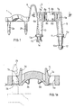
- Figure 1 shows a side view of the cable clamping device;
- Figure 1a shows a section of one of the brackets making part of the clamping device, taken along the line a-a in fig. 1;
- Figure 2 shows a top view of the terminal board being part of the connector device;
- Figure 3 shows an enlarged partial section view of the terminal board, taken along the line 3-3 in figure 2;
- Figure 4 shows a schematic perspective view of a connector with the cable assembled.
- Referring now to figure 1, it can be seen how the clamping device comprises a clamping bracket 3 and a
bracket 1 equipped with two equalsymmetrical wings brackets 1 and 3 are joined together by means of anarrow strip 4. Thewings bracket 1 are jagged on their inner side. - The bracket 3 consists of a
central part 5 suitable for receiving the cable, and of twoequal openings elastic tongues wings tongues wing tongues central part 5 of the bracket 3 in which the electric cable is housed is equipped with four projectingelements 8b - Referring again to figure 1, it will be noted how two arms, 9 and 10 respectively, leave from the bracket 3, being substantially perpendicular to the latter. The
arm 9 ends in ahead 12 above which anabutment 12a is provided. The arm is also equipped with acollar 11 for acting as a further ledge which can serve as a stop during wiring. Thearm 10 ends in aseat 13 comprised between two collars, one of them, 14, located at the end and the other, 13a, more internally. - Referring now to figure 2, the
terminal board 21, to which the free socket, plug or such is connected, is equipped, as is already known, withholes fixing holes notch 23. - The
terminal board 21 is equipped with a further throughhole 25, along its periphery. This hole is internally provided with fourequal projections hole 25 can be better seen in figure 3, where two of the projections, in particular 26c and 26d, are to be seen. - Lastly, there is a
slot 27 cut out on the periphery of theterminal board 21, which is inserted obliquely into saidterminal board 21 and is rounded at its end in a semicircle. This is located at a distance which corresponds to the distance between the twoarms slot 27 corresponds to the tangent of the circle which has thehole 25 at its centre. - Now the connection of the cable clamping device to the
terminal board 21 will be described: the arm 9 (see figure 1) of the device is brought over thehole 25; thepin 11 with itshemispherical head 12 is then inserted into thehole 25. Theheads 12 slides within theprojections hole 25. In this way, theprojections head 12, where the diameter of thepin 11 is narrower and prevents thearm 9 from being extracted from theterminal board 21. - The
other arm 10 of the bracket 3 is made to rotate around thepin 13 and positioned in correspondence with theslot 27. Then thearm 10 is pressed into theslot 27, slides along it and comes to abut against the semicircular rounded form at the terminal end of the slot. - In this way the bracket 3 is near to the cable which, in order to be clamped, has only to be gripped by the
other bracket 1 whosewings openings - If it is desired to disconnect
bracket 1 from bracket 3, in order to release the cable, it is sufficient to slightly push on thewings tongues wings openings - In this way a connector device with free plug has been produced which is capable of avoiding the drawbacks previously mentioned, in fact:
- a) wiring is much simpler and quicker, in that the
holes - b) by constructing the device in two pieces, the parts obtained are much simpler and easier to manufacture; what is more, they can be supplied separately;
- c) the terminal board produced for the device being the object of the invention can also be used for fixed plugs; by standardizing this component in such a way, an appreciable economic advantage is achieved.
Claims (4)
Priority Applications (1)
| Application Number | Priority Date | Filing Date | Title |
|---|---|---|---|
| AT89113137T ATE84643T1 (en) | 1988-07-29 | 1989-07-18 | MOVABLE PLUG AND COUPLING FOR ELECTRICAL CABLES. |
Applications Claiming Priority (2)
| Application Number | Priority Date | Filing Date | Title |
|---|---|---|---|
| IT2159088 | 1988-07-29 | ||
| IT8821590A IT1227022B (en) | 1988-07-29 | 1988-07-29 | CONNECTOR FOR ELECTRIC CABLES WITH PLUG AND STEERING SOCKET. |
Publications (2)
| Publication Number | Publication Date |
|---|---|
| EP0353539A1 true EP0353539A1 (en) | 1990-02-07 |
| EP0353539B1 EP0353539B1 (en) | 1993-01-13 |
Family
ID=11184034
Family Applications (1)
| Application Number | Title | Priority Date | Filing Date |
|---|---|---|---|
| EP89113137A Expired - Lifetime EP0353539B1 (en) | 1988-07-29 | 1989-07-18 | Connector with free plug and socket for electric cables |
Country Status (5)
| Country | Link |
|---|---|
| EP (1) | EP0353539B1 (en) |
| AT (1) | ATE84643T1 (en) |
| DE (1) | DE68904375T2 (en) |
| ES (1) | ES2037345T3 (en) |
| IT (1) | IT1227022B (en) |
Cited By (10)
| Publication number | Priority date | Publication date | Assignee | Title |
|---|---|---|---|---|
| US5588871A (en) * | 1992-11-03 | 1996-12-31 | Necchi Compressori S.R.L. | Terminal box for hermetic compressors |
| US5814770A (en) * | 1993-11-08 | 1998-09-29 | Raychem Corporation | Cable closure |
| EP1137140A2 (en) * | 2000-03-17 | 2001-09-26 | Tridonic Bauelemente GmbH | Strain relief for an electrical cable |
| GB2372890A (en) * | 1998-07-08 | 2002-09-04 | R W Data Ltd | Gripping of electrical cables |
| WO2003061078A1 (en) * | 2002-01-04 | 2003-07-24 | Tyco Electronics Corporation | Strain relief for electrical cable |
| EP1489712A2 (en) * | 2003-06-16 | 2004-12-22 | BSH Bosch und Siemens Hausgeräte GmbH | Strain relief for electrical cable |
| GB2459146A (en) * | 2008-04-10 | 2009-10-21 | Calder Ltd | Cable retention bracket |
| EP2436987A2 (en) | 2010-09-29 | 2012-04-04 | BSH Bosch und Siemens Hausgeräte GmbH | A cooker with an arrangement preventing the cutting of cables |
| EP2492563A1 (en) | 2011-02-25 | 2012-08-29 | Raywal Holding SAS | Clamp for a pipe or cable. |
| FR3125926A1 (en) * | 2021-07-29 | 2023-02-03 | Latelec | Angled strain relief cable connection. |
Citations (4)
| Publication number | Priority date | Publication date | Assignee | Title |
|---|---|---|---|---|
| DE1515815B1 (en) * | 1964-06-01 | 1970-02-05 | Heyman Mfg Co | One-piece cable strain relief sleeve |
| DE2023168A1 (en) * | 1969-05-14 | 1970-12-03 | Ceil Sa | Device for clamping a cable, pipe or the like. |
| DE2433347A1 (en) * | 1974-07-11 | 1976-01-22 | Bals Elektro | Electric power cable plug connector - has swinging arm in housing supported on inner plate, clamped around cable end |
| DE3305767A1 (en) * | 1983-02-19 | 1984-08-30 | Kalthoff GmbH, 5885 Schalksmühle | Tension-relief clamp |
-
1988
- 1988-07-29 IT IT8821590A patent/IT1227022B/en active
-
1989
- 1989-07-18 DE DE8989113137T patent/DE68904375T2/en not_active Expired - Fee Related
- 1989-07-18 EP EP89113137A patent/EP0353539B1/en not_active Expired - Lifetime
- 1989-07-18 ES ES198989113137T patent/ES2037345T3/en not_active Expired - Lifetime
- 1989-07-18 AT AT89113137T patent/ATE84643T1/en not_active IP Right Cessation
Patent Citations (4)
| Publication number | Priority date | Publication date | Assignee | Title |
|---|---|---|---|---|
| DE1515815B1 (en) * | 1964-06-01 | 1970-02-05 | Heyman Mfg Co | One-piece cable strain relief sleeve |
| DE2023168A1 (en) * | 1969-05-14 | 1970-12-03 | Ceil Sa | Device for clamping a cable, pipe or the like. |
| DE2433347A1 (en) * | 1974-07-11 | 1976-01-22 | Bals Elektro | Electric power cable plug connector - has swinging arm in housing supported on inner plate, clamped around cable end |
| DE3305767A1 (en) * | 1983-02-19 | 1984-08-30 | Kalthoff GmbH, 5885 Schalksmühle | Tension-relief clamp |
Cited By (14)
| Publication number | Priority date | Publication date | Assignee | Title |
|---|---|---|---|---|
| US5588871A (en) * | 1992-11-03 | 1996-12-31 | Necchi Compressori S.R.L. | Terminal box for hermetic compressors |
| US5814770A (en) * | 1993-11-08 | 1998-09-29 | Raychem Corporation | Cable closure |
| GB2372890B (en) * | 1998-07-08 | 2002-11-06 | R W Data Ltd | Gripping of electrical cables |
| GB2372890A (en) * | 1998-07-08 | 2002-09-04 | R W Data Ltd | Gripping of electrical cables |
| EP1137140A3 (en) * | 2000-03-17 | 2003-09-17 | TridonicAtco GmbH & Co. KG | Strain relief for an electrical cable |
| EP1137140A2 (en) * | 2000-03-17 | 2001-09-26 | Tridonic Bauelemente GmbH | Strain relief for an electrical cable |
| WO2003061078A1 (en) * | 2002-01-04 | 2003-07-24 | Tyco Electronics Corporation | Strain relief for electrical cable |
| US6706970B2 (en) | 2002-01-04 | 2004-03-16 | Tyco Electronics Corporation | Strain relief for electrical cable |
| EP1489712A2 (en) * | 2003-06-16 | 2004-12-22 | BSH Bosch und Siemens Hausgeräte GmbH | Strain relief for electrical cable |
| EP1489712A3 (en) * | 2003-06-16 | 2010-06-16 | BSH Bosch und Siemens Hausgeräte GmbH | Strain relief for electrical cable |
| GB2459146A (en) * | 2008-04-10 | 2009-10-21 | Calder Ltd | Cable retention bracket |
| EP2436987A2 (en) | 2010-09-29 | 2012-04-04 | BSH Bosch und Siemens Hausgeräte GmbH | A cooker with an arrangement preventing the cutting of cables |
| EP2492563A1 (en) | 2011-02-25 | 2012-08-29 | Raywal Holding SAS | Clamp for a pipe or cable. |
| FR3125926A1 (en) * | 2021-07-29 | 2023-02-03 | Latelec | Angled strain relief cable connection. |
Also Published As
| Publication number | Publication date |
|---|---|
| DE68904375D1 (en) | 1993-02-25 |
| IT8821590A0 (en) | 1988-07-29 |
| ATE84643T1 (en) | 1993-01-15 |
| IT1227022B (en) | 1991-03-08 |
| ES2037345T3 (en) | 1993-06-16 |
| EP0353539B1 (en) | 1993-01-13 |
| DE68904375T2 (en) | 1993-06-24 |
Similar Documents
| Publication | Publication Date | Title |
|---|---|---|
| US4440465A (en) | Electrical plug connector lock | |
| JPH0652673B2 (en) | Connection terminal for electric conductor | |
| EP1122822B1 (en) | Connector | |
| US5064389A (en) | Electrical slave connector | |
| AU743965B2 (en) | Electrical connector | |
| EP0353539A1 (en) | Connector with free plug and socket for electric cables | |
| US4605273A (en) | Parallel-blade/twist-lock adapter plug | |
| WO1988003713A1 (en) | Electrical connector devices and methods | |
| US5704814A (en) | Electrical connector | |
| JP3047988U (en) | Electrical connector | |
| US10950998B2 (en) | Wire guide for insulation displacement contact (IDC) | |
| GB1600964A (en) | Electrical fittings | |
| US11424576B2 (en) | Retention devices | |
| EP0195472A1 (en) | Electrical plug | |
| EP0282194B1 (en) | Electrical cable connector | |
| US20220069513A1 (en) | Poke-in wire connector for power connector assembly | |
| JPH02139876A (en) | Cable terminal board | |
| GB2097601A (en) | Cord grips for electrical plugs or appliances especially for non-rewireable plugs | |
| JP3044663B2 (en) | Wiring equipment | |
| US4360242A (en) | Self-fastening electrical connector | |
| CN211456102U (en) | Fastening assembly for plug connector and plug connector | |
| US4802870A (en) | Universal electrical connector | |
| CN111009780A (en) | Fastening assembly for plug connector and plug connector | |
| JPH03138872A (en) | Connector for coaxial cable | |
| WO2023059285A1 (en) | A terminal assembly |
Legal Events
| Date | Code | Title | Description |
|---|---|---|---|
| PUAI | Public reference made under article 153(3) epc to a published international application that has entered the european phase |
Free format text: ORIGINAL CODE: 0009012 |
|
| AK | Designated contracting states |
Kind code of ref document: A1 Designated state(s): AT BE CH DE ES FR GB GR IT LI LU NL SE |
|
| 17P | Request for examination filed |
Effective date: 19900625 |
|
| 17Q | First examination report despatched |
Effective date: 19920506 |
|
| GRAA | (expected) grant |
Free format text: ORIGINAL CODE: 0009210 |
|
| AK | Designated contracting states |
Kind code of ref document: B1 Designated state(s): AT BE CH DE ES FR GB GR IT LI LU NL SE |
|
| PG25 | Lapsed in a contracting state [announced via postgrant information from national office to epo] |
Ref country code: NL Effective date: 19930113 Ref country code: LI Effective date: 19930113 Ref country code: GR Free format text: LAPSE BECAUSE OF FAILURE TO SUBMIT A TRANSLATION OF THE DESCRIPTION OR TO PAY THE FEE WITHIN THE PRESCRIBED TIME-LIMIT Effective date: 19930113 Ref country code: CH Effective date: 19930113 Ref country code: BE Effective date: 19930113 |
|
| REF | Corresponds to: |
Ref document number: 84643 Country of ref document: AT Date of ref document: 19930115 Kind code of ref document: T |
|
| REF | Corresponds to: |
Ref document number: 68904375 Country of ref document: DE Date of ref document: 19930225 |
|
| ITF | It: translation for a ep patent filed |
Owner name: DR. ING. A. RACHELI & C. |
|
| ET | Fr: translation filed | ||
| REG | Reference to a national code |
Ref country code: CH Ref legal event code: PL |
|
| NLV1 | Nl: lapsed or annulled due to failure to fulfill the requirements of art. 29p and 29m of the patents act | ||
| REG | Reference to a national code |
Ref country code: ES Ref legal event code: FG2A Ref document number: 2037345 Country of ref document: ES Kind code of ref document: T3 |
|
| PG25 | Lapsed in a contracting state [announced via postgrant information from national office to epo] |
Ref country code: LU Free format text: LAPSE BECAUSE OF NON-PAYMENT OF DUE FEES Effective date: 19930731 |
|
| PLBE | No opposition filed within time limit |
Free format text: ORIGINAL CODE: 0009261 |
|
| STAA | Information on the status of an ep patent application or granted ep patent |
Free format text: STATUS: NO OPPOSITION FILED WITHIN TIME LIMIT |
|
| 26N | No opposition filed | ||
| PGFP | Annual fee paid to national office [announced via postgrant information from national office to epo] |
Ref country code: SE Payment date: 19940620 Year of fee payment: 6 |
|
| PGFP | Annual fee paid to national office [announced via postgrant information from national office to epo] |
Ref country code: GB Payment date: 19940708 Year of fee payment: 6 |
|
| PGFP | Annual fee paid to national office [announced via postgrant information from national office to epo] |
Ref country code: FR Payment date: 19940718 Year of fee payment: 6 |
|
| PGFP | Annual fee paid to national office [announced via postgrant information from national office to epo] |
Ref country code: AT Payment date: 19940725 Year of fee payment: 6 |
|
| EAL | Se: european patent in force in sweden |
Ref document number: 89113137.7 |
|
| PG25 | Lapsed in a contracting state [announced via postgrant information from national office to epo] |
Ref country code: GB Effective date: 19950718 Ref country code: AT Effective date: 19950718 |
|
| PG25 | Lapsed in a contracting state [announced via postgrant information from national office to epo] |
Ref country code: SE Effective date: 19950719 |
|
| GBPC | Gb: european patent ceased through non-payment of renewal fee |
Effective date: 19950718 |
|
| EUG | Se: european patent has lapsed |
Ref document number: 89113137.7 |
|
| PG25 | Lapsed in a contracting state [announced via postgrant information from national office to epo] |
Ref country code: FR Effective date: 19960430 |
|
| REG | Reference to a national code |
Ref country code: FR Ref legal event code: ST |
|
| REG | Reference to a national code |
Ref country code: FR Ref legal event code: ST |
|
| REG | Reference to a national code |
Ref country code: FR Ref legal event code: ST |
|
| PGFP | Annual fee paid to national office [announced via postgrant information from national office to epo] |
Ref country code: ES Payment date: 19990706 Year of fee payment: 11 |
|
| PGFP | Annual fee paid to national office [announced via postgrant information from national office to epo] |
Ref country code: DE Payment date: 19990721 Year of fee payment: 11 |
|
| PG25 | Lapsed in a contracting state [announced via postgrant information from national office to epo] |
Ref country code: ES Free format text: LAPSE BECAUSE OF NON-PAYMENT OF DUE FEES Effective date: 20000719 |
|
| PG25 | Lapsed in a contracting state [announced via postgrant information from national office to epo] |
Ref country code: DE Free format text: LAPSE BECAUSE OF NON-PAYMENT OF DUE FEES Effective date: 20010501 |
|
| REG | Reference to a national code |
Ref country code: ES Ref legal event code: FD2A Effective date: 20010810 |
|
| PG25 | Lapsed in a contracting state [announced via postgrant information from national office to epo] |
Ref country code: IT Free format text: LAPSE BECAUSE OF NON-PAYMENT OF DUE FEES Effective date: 20050718 |