EP0354670A1 - Auto-off coffee brewing system - Google Patents
Auto-off coffee brewing system Download PDFInfo
- Publication number
- EP0354670A1 EP0354670A1 EP89307279A EP89307279A EP0354670A1 EP 0354670 A1 EP0354670 A1 EP 0354670A1 EP 89307279 A EP89307279 A EP 89307279A EP 89307279 A EP89307279 A EP 89307279A EP 0354670 A1 EP0354670 A1 EP 0354670A1
- Authority
- EP
- European Patent Office
- Prior art keywords
- heat generator
- water
- thermostat
- coffee
- reservoir
- Prior art date
- Legal status (The legal status is an assumption and is not a legal conclusion. Google has not performed a legal analysis and makes no representation as to the accuracy of the status listed.)
- Withdrawn
Links
Images


Classifications
-
- A—HUMAN NECESSITIES
- A47—FURNITURE; DOMESTIC ARTICLES OR APPLIANCES; COFFEE MILLS; SPICE MILLS; SUCTION CLEANERS IN GENERAL
- A47J—KITCHEN EQUIPMENT; COFFEE MILLS; SPICE MILLS; APPARATUS FOR MAKING BEVERAGES
- A47J31/00—Apparatus for making beverages
- A47J31/44—Parts or details or accessories of beverage-making apparatus
- A47J31/54—Water boiling vessels in beverage making machines
- A47J31/542—Continuous-flow heaters
- A47J31/545—Control or safety devices
-
- A—HUMAN NECESSITIES
- A47—FURNITURE; DOMESTIC ARTICLES OR APPLIANCES; COFFEE MILLS; SPICE MILLS; SUCTION CLEANERS IN GENERAL
- A47J—KITCHEN EQUIPMENT; COFFEE MILLS; SPICE MILLS; APPARATUS FOR MAKING BEVERAGES
- A47J31/00—Apparatus for making beverages
- A47J31/04—Coffee-making apparatus with rising pipes
- A47J31/057—Coffee-making apparatus with rising pipes with water container separated from beverage container, the hot water passing the filter only once i.e. classical type of drip coffee makers
- A47J31/0573—Coffee-making apparatus with rising pipes with water container separated from beverage container, the hot water passing the filter only once i.e. classical type of drip coffee makers with flow through heaters
-
- A—HUMAN NECESSITIES
- A47—FURNITURE; DOMESTIC ARTICLES OR APPLIANCES; COFFEE MILLS; SPICE MILLS; SUCTION CLEANERS IN GENERAL
- A47J—KITCHEN EQUIPMENT; COFFEE MILLS; SPICE MILLS; APPARATUS FOR MAKING BEVERAGES
- A47J31/00—Apparatus for making beverages
- A47J31/44—Parts or details or accessories of beverage-making apparatus
- A47J31/54—Water boiling vessels in beverage making machines
- A47J31/56—Water boiling vessels in beverage making machines having water-level controls; having temperature controls
-
- A—HUMAN NECESSITIES
- A47—FURNITURE; DOMESTIC ARTICLES OR APPLIANCES; COFFEE MILLS; SPICE MILLS; SUCTION CLEANERS IN GENERAL
- A47J—KITCHEN EQUIPMENT; COFFEE MILLS; SPICE MILLS; APPARATUS FOR MAKING BEVERAGES
- A47J31/00—Apparatus for making beverages
- A47J31/44—Parts or details or accessories of beverage-making apparatus
- A47J31/58—Safety devices
Definitions
- the present invention relates generally to a coffee brewing system which utilizes an insulated carafe to receive brewed coffee and automatically turns itself off under appropriate conditions.
- the present invention is directed towards a coffee brewing system which may utilize an insulated carafe to receive the brewed coffee.
- the system automatically turns itself off a short time after completion of a brew cycle. It also turns off automatically a specified time after a brew cycle is initiated when calcification is so extreme that flow of water through the unit is totally prevented. Additionally, as a safety feature, the system also turns off automatically in the case of a "dry run", that is, a short specified time after accidental energization when no water is in the reservoir.
- a lamp may be lighted when a brew cycle is in progress but it is extinguished at other times.
- a brewing system embodying the invention employs a water reservoir of finite capacity which is filled to a preselected level to achieve the number of brewed cups desired by the user.
- a water supply conduit extends between the reservoir and a brewing station comprised of a brew basket supporting a filter into which a desired quantity of ground coffee is placed.
- a first electrically energizable heat generator is provided for heating the water in the supply conduit to a sufficient extent as it flows from the reservoir to the brewing station to enable coffee to be brewed at the brewing station.
- the reservoir is substantially depleted of water at the end of a complete brew cycle.
- a first automatic thermostat in heat exchange relationship with the first heat generator is operable to control the temperature thereof. The first thermostat is automatically movable from a closed position to an open position to deenergize the first heat generator when its temperature exceeds a predetermined value.
- the system also utilizes a second electrically energizable heat generator which is responsive to operation of the first thermostat for generating heat when the first thermostat is in the open position and non functioning when the first thermostat is in the closed position.
- a manual reset, or second, thermostat in heat exchange relationship with the second heat generator is selectively movable to a closed position enabling the first heat generator to continue to be energized when the automatic thermostat is open. However, subsequently, a predetermined period of time after water ceases to flow through the supply conduit, the second thermostat moves to an open position to deenergize the first heat generator.
- water may cease to flow through the supply conduit either after completion of the brew cycle or when mineral deposits in the supply conduit build up to such an extent that water can no longer flow between the reservoir and the brew station.
- it is normal for mineral deposits to form in the supply conduit. While it is desirable to clean the supply conduit periodically, it is not the intent of the system to penalize the user for failure to regularly clean the system. That is, the system will continue to operate even though there has been some mineral build up which reduces the flow rate of water between the reservoir and the brew station and which therefore results in a longer brew cycle than when there were no deposits in the conduit.
- the deposits build to such an extent that water can no longer pass through the conduit, for reasons of safety it is necessary to turn the machine off and the invention is able to achieve that purpose.
- the automatic, or first, thermostat is caused to open and close intermittently. That is, as heat builds up in the first heat generator because of reduced coolant (that is, water) flow rate, the automatic thermostat opens, but then subsequently closes again because of the continued passage through the supply conduit of fresh cool water. This process continues until all of the water in the reservoir has become depleted at which time the automatic thermostat opens and remains open for an extended duration since the heat transfer capability of air is far less than that of water. After the automatic thermostat has remained open for a predetermined period of time, the manual reset, or second, thermostat is likewise caused to open because of extended heating of the second heat generator and remains open until it is manually reset at some subsequent time.
- an indicator in the form of a neon lamp is lighted but becomes extinguished either when the brew cycle is completed or when the system becomes deenergized because of an extreme mineral build up in the supply conduit. In short, the indicator is extinguished only when the manual thermostat opens.
- the machine 20 includes a main housing 22 adapted to rest on a counter or other convenient location.
- the housing 22 contains all of the necessary components for brewing coffee, specifically, a self contained water reservoir 24, a water heating and pumping system 26, and a brewing station 28 including a coffee basket 30.
- a receptacle 32 for receiving brewed coffee is preferably in the form of an insulated carafe which is an independent component of the brewing machine 20. It is noteworthy that when the carafe assumes the coffee receiving position indicated in Fig. 1, it rests on a support plate 34 which is an integral part of the main housing 22 but is not heated in the manner of many, if not most, of the domestic brewing machines currently being sold. Being insulated, the carafe 32 retains the warmth and flavor of the coffee for a long period of time without requiring continued heating after the brewing process has been completed.
- the water reservoir 24 is self contained and may be filled by way of a lid 36 which can be suitably pivoted between open and closed positions.
- the reservoir itself may be removable from the remainder of the housing 22 for purposes of cleaning or to enable it to be filled from a faucet with an amount of water equivalent to the number of cups of coffee desired.
- a valve 38 biased closed when the reservoir is removed from the housing is again opened and enables the water in the reservoir to enter the system.
- the water heating and pumping system 26 includes a water supply conduit 40 which extends generally between the water reservoir and the brewing station 28. As indicated by dashed lines in Fig. 1, the water supply conduit 40 first descends from the reservoir, then reverses direction to ascend from the base region of the machine 20, making connection with a shower plate 42 which overlies the coffee basket 30.
- the system 26 also includes an electrically energizable hot water generator 44 (Fig. 3) which operates in a known manner for heating the water in the supply conduit to a sufficient extent as it flows from the reservoir 24 to the brewing station 28 to enable coffee to be brewed at the brewing station.
- the coffee brewing machine 20 is AC powered as represented by a plug 52 which can be connected in a customary manner to a 120 VAC outlet receptacle.
- a main off-on switch 54 (Figs. 1-3) is operated in order to enable operation of the machine 20 to proceed.
- an actual brewing cycle will not commence until a reset button 56 associated with a manual reset thermostat 58 has also been actuated.
- the manual reset thermostat 58 is one component of a thermal relay 60 of a type which is commercially available, one such device suitable for purposes of the invention being Model 607 TDR manufactured by Texas Instruments, Inc. of Paris, Kentucky.
- a primary feature of the coffee brewing machine 20 resides in its ability to turn off its operating mechanism when it determines that flow of water through the supply conduit 40 is non existent. Such a situation may occur in the first instance if the user fails to put water in the reservoir 24. It also occurs at the end of a complete brew cycle. Finally, it additionally occurs at such time that the supply conduit 40 becomes so calcified that water can no longer pass through from the reservoir 24 to the brewing station 28.
- An electrical circuit 61 schematically presented in Fig. 3, enables normal operation of the brewing machine 20 but has the added ability of turning the machine off automatically after the occurrence of any of these events.
- the hot water generator 44 includes a water heater 62 with a high power output, typically 975 to 1000 watts and therefore exhibiting a relatively low resistance value, typically 14 ohms.
- the source of power, as represented by the plug 52, and the switches 54 and 58 are all electrically in series with the water heater 62 as is an automatic thermostat 64 associated with the water heater.
- the switch contacts of the automatic thermostat 64 are normally biased to a closed position which has the effect of energizing the water heater 62 when the switches 54 and 58 are closed. However, the thermostat 64 is caused to open when the temperature of the water heater exceeds a predetermined magnitude.
- the temperature of the water heater exceeds such a predetermined magnitude in each of the instances mentioned above, namely, when there is a lack of flow of water through the conduit 40 either for lack of water initially in the reservoir or because a brew cycle has been completed, or when calcification of the supply conduit 40 is so great that water is unable to flow.
- the thermostat is caused to cycle between open and closed positions. That is, heat builds up in the hot water generator 44 to the extent that the thermostat opens, but because water flow continues, albeit at a reduced rate, the outer structural components of the water generator are caused to cool down permitting the contacts of the thermostat to close once again to thereby once again energize the water heater.
- Fig. 4 is a time versus temperature diagram which illustrates the operation of the brewing machine 20 when the supply conduit 40 is totally clean.
- Fig. 5 in contrast, is a time versus temperature diagram illustrating the operation of the brewing machine when it has a partially calcified supply conduit.
- the thermal relay 60 when utilized in conjunction with the hot water generator 44 provides this desirable result.
- the thermal relay includes an auxiliary heater 66 which, in contrast to the water heater 62, is a lower power, typically 2 to 10 watts, high resistance, typically approximately 3000 ohms, device.
- the manual reset thermostat 58 is associated with the auxiliary heater 66 and is responsive to the auxiliary heater. That is, the contacts of the thermostat 58 are caused to open when the temperature resulting from the auxiliary heater 66 being energized reaches a predetermined level. It is highly desirable that the thermal relay 60 be thermally isolated from the heater 62 so that the thermostat 58 is subject only to heat from the auxiliary heater 66 and not substantially affected by heat from the water heater 62.
- the auxiliary heater 66 is electrically in parallel with the automatic thermostat 64.
- the automatic thermostat 64 opens, the auxiliary heater 66 becomes energized. If it remains energized for a predetermined period of time, it causes the manual reset thermostat 58 to open and the latter will remain open until the reset button is again manually operated to close the contacts of the manual reset thermostat 58.
- the manual reset thermostat 58 it would not be desirable for the manual reset thermostat 58 to open when the automatic thermostat 64 is cycling between its open and closed positions because of a partially calcified condition. However, in any of the other instances mentioned, it would be desirable for the manual reset thermostat to open after a predetermined period of time which will assure that, indeed, there is no water flow in the supply conduit 40, yet before any damage would occur to any of the components of the machine. A preferred duration for such a time delay would be in the range of one to two minutes after the automatic thermostat 64 has opened and remains open.
- a neon lamp 68 and an associated protective resistor 70 are electrically in parallel with the other components illustrated in the circuit such that the lamp remains lighted to indicate that a brew cycle is under way so long as the main switch 54 is closed and the manual reset thermostat 58 is closed. When either of those switches is open, it is indicative of the fact that either a brew cycle has been completed, or has not yet begun.
- the circuit 61 in Fig. 3 includes a primary fuse 72 and a secondary fuse 74 which are electrically in series between the power source as represented by the plug 52 and the water heater 62. It is desirable that the fuses 72, 74 be of staggered rupture values within the range of safety so as to assure that both fuses could not originate from the same bad lot. This minimizes the possibility that a product failure would occur.
Abstract
A coffee brewing machine utilizes an insulated carafe (32) to receive the brewed coffee and automatically turns itself off a short time after completion of a brew cycle. The machine also turns off automatically a specified time after a brew cycle is initiated when calcification is so extreme that flow of water through the unit is totally prevented. Additionally, as a safety feature, the system also turns off automatically in the case of a "dry run", that is, a short specified time after accidential energization when no water is in the reservoir. A lamp (68) is lighted when a brew cycle is in progress but is extinguished at other times.
Description
- The present invention relates generally to a coffee brewing system which utilizes an insulated carafe to receive brewed coffee and automatically turns itself off under appropriate conditions.
- In the past, coffee brewing systems intended for domestic use have customarily been equipped with uninsulated receptacles to receive the brewed coffee. These systems typically provide a heater plate on which the receptacle is supported after completion of the brew cycle. The purpose of the heater plate is to keep the coffee warm until it is completely consumed or discarded. However, such an arrangement is costly in that it requires the continued expenditure of power. It also heats the environment which is doubly costly when the room in which the system is located is air conditioned. Such continued heating of coffee also detracts from its flavor when the time period is an extended one. Additionally, drippage of coffee is often known to occur onto the heater plate. This causes burning of the coffee on the heater plate, customarily leaving an unpleasant hardened residue which can subsequently become transferred to the receptacle. Eventually, it becomes necessary to clean the surfaces of both the heater plate and the bottom of the receptacle.
- Devices have previously been known for automatically turning off appliances at some desired time. One such invention is disclosed in U.S. Patent No. 4,480,173 to Butterfield which describes a water heater in the nature of a pressure cooker. In the instance of that patent, a water level transducer controls a motorized inlet valve to close the valve when the water level in the tank reaches a predetermined level and opens the valve when the water falls below that level. However, the Butterfield patent does not disclose a coffee brewing system and is not concerned with turning the heater off a predetermined time after a brew cycle intended to yield a predetermined amount of coffee has been accomplished.
- More directly concerned with coffee brewing processes are the U.S. Patents, No. 3,869,968 to Ihlenfeld and No. 3,759,161 to Anderson. In each instance, the patent discloses a coffee brewer of a conventional type which utilizes a heater plate to maintain the temperature of the brewed coffee in the coffee pot after completion of a brew cycle. In each instance, provision is made for deenergizing the heater mechanism used in the brewing operation, while continuing to energize the auxiliary heater mechanism used to maintain the temperature of the brewed coffee.
- It was with knowledge of the prior art as generally represented by the patents just discussed, and appreciation of their drawbacks that the present invention was made. The present invention is directed towards a coffee brewing system which may utilize an insulated carafe to receive the brewed coffee. According to the invention, the system automatically turns itself off a short time after completion of a brew cycle. It also turns off automatically a specified time after a brew cycle is initiated when calcification is so extreme that flow of water through the unit is totally prevented. Additionally, as a safety feature, the system also turns off automatically in the case of a "dry run", that is, a short specified time after accidental energization when no water is in the reservoir. A lamp may be lighted when a brew cycle is in progress but it is extinguished at other times.
- A brewing system embodying the invention employs a water reservoir of finite capacity which is filled to a preselected level to achieve the number of brewed cups desired by the user. A water supply conduit extends between the reservoir and a brewing station comprised of a brew basket supporting a filter into which a desired quantity of ground coffee is placed. A first electrically energizable heat generator is provided for heating the water in the supply conduit to a sufficient extent as it flows from the reservoir to the brewing station to enable coffee to be brewed at the brewing station. During normal operation, the reservoir is substantially depleted of water at the end of a complete brew cycle. A first automatic thermostat in heat exchange relationship with the first heat generator is operable to control the temperature thereof. The first thermostat is automatically movable from a closed position to an open position to deenergize the first heat generator when its temperature exceeds a predetermined value.
- The system also utilizes a second electrically energizable heat generator which is responsive to operation of the first thermostat for generating heat when the first thermostat is in the open position and non functioning when the first thermostat is in the closed position. A manual reset, or second, thermostat in heat exchange relationship with the second heat generator is selectively movable to a closed position enabling the first heat generator to continue to be energized when the automatic thermostat is open. However, subsequently, a predetermined period of time after water ceases to flow through the supply conduit, the second thermostat moves to an open position to deenergize the first heat generator.
- It is noteworthy that water may cease to flow through the supply conduit either after completion of the brew cycle or when mineral deposits in the supply conduit build up to such an extent that water can no longer flow between the reservoir and the brew station. In the course of operation of the brewing system, it is normal for mineral deposits to form in the supply conduit. While it is desirable to clean the supply conduit periodically, it is not the intent of the system to penalize the user for failure to regularly clean the system. That is, the system will continue to operate even though there has been some mineral build up which reduces the flow rate of water between the reservoir and the brew station and which therefore results in a longer brew cycle than when there were no deposits in the conduit. However, when the deposits build to such an extent that water can no longer pass through the conduit, for reasons of safety it is necessary to turn the machine off and the invention is able to achieve that purpose.
- Thus, as mineral deposits, often times referred to as "calcification" becomes more aggravated, the automatic, or first, thermostat is caused to open and close intermittently. That is, as heat builds up in the first heat generator because of reduced coolant (that is, water) flow rate, the automatic thermostat opens, but then subsequently closes again because of the continued passage through the supply conduit of fresh cool water. This process continues until all of the water in the reservoir has become depleted at which time the automatic thermostat opens and remains open for an extended duration since the heat transfer capability of air is far less than that of water. After the automatic thermostat has remained open for a predetermined period of time, the manual reset, or second, thermostat is likewise caused to open because of extended heating of the second heat generator and remains open until it is manually reset at some subsequent time.
- During the time that a brew cycle is in progress, an indicator in the form of a neon lamp is lighted but becomes extinguished either when the brew cycle is completed or when the system becomes deenergized because of an extreme mineral build up in the supply conduit. In short, the indicator is extinguished only when the manual thermostat opens.
- Other and further features, objects, advantages, and benefits of the invention will become apparent from the following description taken in conjunction with the following drawings. It is to be understood that both the foregoing general description and the following detailed description are exemplary and explanatory but are not restrictive of the invention. The accompanying drawings, which are incorporated in and constitute a part of this invention, illustrate one of the embodiments of the invention and, together with the description, serve to explain the principles of the invention in general terms.
-
- Fig. 1 is a front elevation view illustrating an automatic coffee brewing machine which embodies the present invention, certain parts being cut away and shown in section;
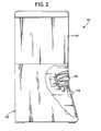
- Fig. 2 is a side elevation view of the coffee brewing machine illustrated in Fig. 1, certain parts also being cut away and shown in section;
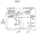
- Fig. 3 is a schematic drawing of an electrical circuit for operating the coffee brewing machine illustrated in Figs. 1 and 2;
- Fig. 4 is a time versus temperature diagram illustrating the operation of the coffee brewing machine of the invention when the supply conduit is totally clean; and
- Fig. 5 is a time versus temperature diagram, similar to Fig. 4, illustrating the operation of the coffee brewing machine when it has a partially calcified supply conduit.
- Attention is now directed to the drawings and, initially, to Figs. 1 and 2 which illustrate an automatic
coffee brewing machine 20 which embodies the present invention. Themachine 20 includes amain housing 22 adapted to rest on a counter or other convenient location. Thehousing 22 contains all of the necessary components for brewing coffee, specifically, a self containedwater reservoir 24, a water heating andpumping system 26, and abrewing station 28 including acoffee basket 30. - A
receptacle 32 for receiving brewed coffee is preferably in the form of an insulated carafe which is an independent component of thebrewing machine 20. It is noteworthy that when the carafe assumes the coffee receiving position indicated in Fig. 1, it rests on asupport plate 34 which is an integral part of themain housing 22 but is not heated in the manner of many, if not most, of the domestic brewing machines currently being sold. Being insulated, thecarafe 32 retains the warmth and flavor of the coffee for a long period of time without requiring continued heating after the brewing process has been completed. - The
water reservoir 24 is self contained and may be filled by way of alid 36 which can be suitably pivoted between open and closed positions. The reservoir itself may be removable from the remainder of thehousing 22 for purposes of cleaning or to enable it to be filled from a faucet with an amount of water equivalent to the number of cups of coffee desired. When thewater reservoir 24 is returned and reattached to thehousing 22, avalve 38 biased closed when the reservoir is removed from the housing is again opened and enables the water in the reservoir to enter the system. - The water heating and
pumping system 26 includes awater supply conduit 40 which extends generally between the water reservoir and thebrewing station 28. As indicated by dashed lines in Fig. 1, thewater supply conduit 40 first descends from the reservoir, then reverses direction to ascend from the base region of themachine 20, making connection with ashower plate 42 which overlies thecoffee basket 30. Thesystem 26 also includes an electrically energizable hot water generator 44 (Fig. 3) which operates in a known manner for heating the water in the supply conduit to a sufficient extent as it flows from thereservoir 24 to thebrewing station 28 to enable coffee to be brewed at the brewing station. - In the general operation of the
machine 20, in a known manner, water flows from thereservoir 24, first descending, then ascending toward theshower plate 42, its ascension being caused by thehot water generator 44. Thereafter, with the aid of a check ball 45 which operates to close thewater supply conduit 40 at its entrance end, the resulting water and steam mixture rises through the ascending portion of theconduit 40 to theshower plate 42. Also in a known manner, afilter 46 of paper or other suitable material is positioned in thecoffee basket 30 to receivefresh ground coffee 48. The hot water pumped by thegenerator 44 passes through a plurality of suitably positionedopenings 50 in theshower plate 42 onto and through theground coffee 48 andfilter 46 for eventual reception by thecarafe 32 when positioned to receive brewed coffee from the coffee basket (Fig. 1). - As illustrated in Fig. 3, the
coffee brewing machine 20 is AC powered as represented by aplug 52 which can be connected in a customary manner to a 120 VAC outlet receptacle. A main off-on switch 54 (Figs. 1-3) is operated in order to enable operation of themachine 20 to proceed. However, an actual brewing cycle will not commence until areset button 56 associated with amanual reset thermostat 58 has also been actuated. Themanual reset thermostat 58 is one component of athermal relay 60 of a type which is commercially available, one such device suitable for purposes of the invention being Model 607 TDR manufactured by Texas Instruments, Inc. of Versailles, Kentucky. - A primary feature of the
coffee brewing machine 20 resides in its ability to turn off its operating mechanism when it determines that flow of water through thesupply conduit 40 is non existent. Such a situation may occur in the first instance if the user fails to put water in thereservoir 24. It also occurs at the end of a complete brew cycle. Finally, it additionally occurs at such time that thesupply conduit 40 becomes so calcified that water can no longer pass through from thereservoir 24 to thebrewing station 28. Anelectrical circuit 61, schematically presented in Fig. 3, enables normal operation of thebrewing machine 20 but has the added ability of turning the machine off automatically after the occurrence of any of these events. - Thus, as seen in Fig. 3, the
hot water generator 44 includes awater heater 62 with a high power output, typically 975 to 1000 watts and therefore exhibiting a relatively low resistance value, typically 14 ohms. The source of power, as represented by theplug 52, and theswitches water heater 62 as is anautomatic thermostat 64 associated with the water heater. The switch contacts of theautomatic thermostat 64 are normally biased to a closed position which has the effect of energizing thewater heater 62 when theswitches thermostat 64 is caused to open when the temperature of the water heater exceeds a predetermined magnitude. The temperature of the water heater exceeds such a predetermined magnitude in each of the instances mentioned above, namely, when there is a lack of flow of water through theconduit 40 either for lack of water initially in the reservoir or because a brew cycle has been completed, or when calcification of thesupply conduit 40 is so great that water is unable to flow. In the instance in which there is water flow, but because of some amount of calcification in thesupply conduit 40, the flow rate is reduced, the thermostat is caused to cycle between open and closed positions. That is, heat builds up in thehot water generator 44 to the extent that the thermostat opens, but because water flow continues, albeit at a reduced rate, the outer structural components of the water generator are caused to cool down permitting the contacts of the thermostat to close once again to thereby once again energize the water heater. - Fig. 4 is a time versus temperature diagram which illustrates the operation of the
brewing machine 20 when thesupply conduit 40 is totally clean. Fig. 5, in contrast, is a time versus temperature diagram illustrating the operation of the brewing machine when it has a partially calcified supply conduit. - While the
hot water generator 44 has provision, as described, for preventing thewater heater 62 from overheating, it, by itself, has no capability for turning off the machine upon the occurrence of any of the events previously mentioned. However, thethermal relay 60 when utilized in conjunction with thehot water generator 44 provides this desirable result. For this purpose, the thermal relay includes anauxiliary heater 66 which, in contrast to thewater heater 62, is a lower power, typically 2 to 10 watts, high resistance, typically approximately 3000 ohms, device. Themanual reset thermostat 58 is associated with theauxiliary heater 66 and is responsive to the auxiliary heater. That is, the contacts of thethermostat 58 are caused to open when the temperature resulting from theauxiliary heater 66 being energized reaches a predetermined level. It is highly desirable that thethermal relay 60 be thermally isolated from theheater 62 so that thethermostat 58 is subject only to heat from theauxiliary heater 66 and not substantially affected by heat from thewater heater 62. - It will be noted, viewing Fig. 3, that the
auxiliary heater 66 is electrically in parallel with theautomatic thermostat 64. Thus, so long as the automatic thermostat remains closed, there will be substantially no current flow through theauxiliary heater 66 and, therefore, it will not be energized to any appreciable extent. However, at such time that theautomatic thermostat 64 opens, theauxiliary heater 66 becomes energized. If it remains energized for a predetermined period of time, it causes themanual reset thermostat 58 to open and the latter will remain open until the reset button is again manually operated to close the contacts of themanual reset thermostat 58. - It will be appreciated that the operational characteristics of the
automatic thermostat 64,manual reset thermostat 58, andauxiliary heater 66 are so chosen that an optimum operation of thebrewing machine 20 will result. - Specifically, it would not be desirable for the
manual reset thermostat 58 to open when theautomatic thermostat 64 is cycling between its open and closed positions because of a partially calcified condition. However, in any of the other instances mentioned, it would be desirable for the manual reset thermostat to open after a predetermined period of time which will assure that, indeed, there is no water flow in thesupply conduit 40, yet before any damage would occur to any of the components of the machine. A preferred duration for such a time delay would be in the range of one to two minutes after theautomatic thermostat 64 has opened and remains open. - A
neon lamp 68 and an associatedprotective resistor 70 are electrically in parallel with the other components illustrated in the circuit such that the lamp remains lighted to indicate that a brew cycle is under way so long as themain switch 54 is closed and themanual reset thermostat 58 is closed. When either of those switches is open, it is indicative of the fact that either a brew cycle has been completed, or has not yet begun. As a further safety feature, thecircuit 61 in Fig. 3 includes aprimary fuse 72 and asecondary fuse 74 which are electrically in series between the power source as represented by theplug 52 and thewater heater 62. It is desirable that thefuses - While the preferred embodiment of the invention has been disclosed in detail, it should be understood by those skilled in the art that various modifications may be made to the illustrated embodiment without departing from the scope as described in the specification and defined in the appended claims.
Claims (16)
1. A coffee brewing machine comprising:
a water reservoir of finite capacity;
a brewing station;
a water supply conduit in communication with and extending between said reservoir and said brewing station;
a first electrically energizable heat generator intermediate said water reservoir and said brewing station for heating water in said water supply conduit to a sufficient extent as it flows from said reservoir to said brewing station to enable coffee to be brewed at said brewing station, said reservoir being substantially depleted of water at the end of a normal complete brew cycle;
first and second temperature sensitive switches electrically in series with said first heat generator, said first switch being responsive to the temperature at said first heat generator and automatically movable from a closed position to an open position when the temperature at said first heat generator exceeds a predetermined magnitude and automatically returning to a closed position when the temperature at said first heat generator falls below said predetermined magnitude by reason of the cooling effect of the continued flow of water through said supply conduit; and
a second heat generator associated with said second switch electrically in parallel with said first switch and operable to generate heat upon opening of said first switch, said second switch being responsive to operation of said second heat generator to open if, after a predetermined lapse of time, said first switch is also open, a condition indicative of the absence of the flow of water through said supply conduit.
2. A coffee brewing machine as set forth in Claim 1 including:
indicator means for indicating that a brew cycle is in progress so long as said second switch remains in the closed position.
indicator means for indicating that a brew cycle is in progress so long as said second switch remains in the closed position.
3. A coffee brewing machine as set forth in Claim 1 or 2
wherein said second switch includes a reset button for selectively moving said second switch to the closed position.
wherein said second switch includes a reset button for selectively moving said second switch to the closed position.
4. A coffee brewing machine comprising:
a water reservoir of finite capacity;
a brewing station;
a water supply conduit in communication with and extending between said reservoir and said brewing station;
a first electrically energizable heat generator intermediate said water reservoir and said brewing station for heating water in said water supply conduit to a sufficient extent as it flows from said reservoir to said brewing station to enable coffee to be brewed at said brewing station, said reservoir being substantially depleted of water at the end of a normal complete brew cycle;
a first thermostat in heat exchange relationship with said first heat generator operable to control the temperature thereof, said first thermostat being biased to a closed position to energize said first heat generator but movable to an open position to deenergize said first heat generator when the temperature thereof exceeds a predetermined value;
a second electrically energizable heat generator responsive to operation of said first thermostat for generating heat when said first thermostat is in said open position and nonfunctioning when said first thermostat is in said closed position; and
a manual reset thermostat in heat exchange relationship with said second heat generator and movable between a closed position for energizing said first heat generator when said first thermostat is closed and an open position to deenergize said first heat generator a predetermined period of time after water ceases to flow through said supply conduit.
5. A coffee brewing machine as set forth in Claim 4
wherein said first thermostat is automatic such that, upon the formation of mineral deposits within said supply conduit, said first thermostat is caused to open and close intermittently so long as water continues to flow through said supply conduit and is caused to open and remain open so long as said manual reset thermostat is closed and water ceases to flow through said supply conduit; and
wherein said manual reset thermostat, in response to the heat produced by said second heat generator, is caused to open said predetermined time after said automatic thermostat opens and remains open.
6. A coffee brewing machine as set forth in Claim 5
wherein said automatic thermostat and said manual reset thermostat are both electrically in series with said first heat generator.
wherein said automatic thermostat and said manual reset thermostat are both electrically in series with said first heat generator.
7. A coffee brewing machine as set forth in any preceding claim
wherein said second heat generator is substantially thermally isolated from said first heat generator.
wherein said second heat generator is substantially thermally isolated from said first heat generator.
8. An electrically operated coffee brewing system comprising:
a water reservoir of finite capacity;
a brewing station from which brewed coffee can be delivered to an insulated receptacle;
a water supply conduit in communication with and extending between said reservoir and said brewing station;
an electrically energizable heat generator intermediate said water reservoir and said brewing station for heating water in said water supply conduit to a sufficient extent as it flows from said reservoir to said brewing station to enable coffee to be brewed at said brewing station, said reservoir being substantially depleted of water at the end of a normal complete brew cycle; and
interruption means for deenergizing said coffee brewing system including said heat generator a predetermined time after water ceases to flow through said supply conduit.
9. A coffee brewing system as set forth in Claim 8
wherein said interruption means includes:
sensing means operable for detecting the absence of water in said supply conduit; and
switch means movable between a closed position for electrically energizing said heat generator and an open position for deenergizing said heat generator, said switch means being biased to a closed position and responsive to operation of said sensing means to move to said open position.
10. A coffee brewing system as set forth in Claim 8
wherein said interruption means includes:
an automatic thermostat in heat exchange relationship with said heat generator operable to control the temperature thereof, said heat generator being a primary heat generator, said automatic thermostat biased to a closed position to energize said first heat generator but movable to an open position to deenergize said first heat generator when the temperature thereof exceeds a predetermined value;
an auxiliary electrically energizable heat generator responsive to operation of said automatic thermostat for generating heat when said automatic thermostat is in said open position and nonfunctioning when said automatic theremostat is in said closed position; and
a manual reset thermostat in heat exchange relationship with said auxiliary heat generator and movable between a closed position for energizing said primary heat generator when said automatic thermostat is closed and an open position to deenergize said primary heat generator a predetermined period of time after water ceases to flow through said supply conduit.
11. A coffee brewing system as set forth in any of Claims 4 to 7 including:
indicator means for indicating that a brew cycle is in progress so long as said manual reset thermostat remains in the closed position.
indicator means for indicating that a brew cycle is in progress so long as said manual reset thermostat remains in the closed position.
12. A coffee brewing system as set forth in Claim 2 or 11
wherein said indicator means is a neon lamp electrically in series with said manual reset thermostat.
wherein said indicator means is a neon lamp electrically in series with said manual reset thermostat.
13. A coffee brewing system as set forth in any of Claims 5, 6 or 10
wherein said automatic thermostat and said manual reset thermostat are both electrically in series with said first heat generator.
wherein said automatic thermostat and said manual reset thermostat are both electrically in series with said first heat generator.
14. A coffee brewing machine as set forth in Claim 10
wherein said auxiliary heat generator is substantially thermally isolated from said first heat generator.
wherein said auxiliary heat generator is substantially thermally isolated from said first heat generator.
15. A coffee brewing machine as set forth in any of Claims 4 to 6, 10 or 14
wherein said manual reset thermostat includes a reset button for selectively moving said manual reset thermostat to the closed position.
wherein said manual reset thermostat includes a reset button for selectively moving said manual reset thermostat to the closed position.
16. A coffee brewing machine as set forth in Claim 10
wherein said heat generator is of a substantially greater power rating than said auxiliary heat generator.
wherein said heat generator is of a substantially greater power rating than said auxiliary heat generator.
Applications Claiming Priority (2)
| Application Number | Priority Date | Filing Date | Title |
|---|---|---|---|
| US07/222,195 US4838152A (en) | 1988-07-21 | 1988-07-21 | Auto-off coffee brewing system |
| US222195 | 1998-12-29 |
Publications (1)
| Publication Number | Publication Date |
|---|---|
| EP0354670A1 true EP0354670A1 (en) | 1990-02-14 |
Family
ID=22831269
Family Applications (1)
| Application Number | Title | Priority Date | Filing Date |
|---|---|---|---|
| EP89307279A Withdrawn EP0354670A1 (en) | 1988-07-21 | 1989-07-19 | Auto-off coffee brewing system |
Country Status (3)
| Country | Link |
|---|---|
| US (1) | US4838152A (en) |
| EP (1) | EP0354670A1 (en) |
| CA (1) | CA1321887C (en) |
Cited By (2)
| Publication number | Priority date | Publication date | Assignee | Title |
|---|---|---|---|---|
| WO1999039619A1 (en) * | 1998-02-09 | 1999-08-12 | Koninklijke Philips Electronics N.V. | Apparatus for preparing beverages with end of brew phase detection |
| EP1129653A1 (en) * | 2000-03-03 | 2001-09-05 | BSH Bosch und Siemens Hausgeräte GmbH | Method and device for determining the calcification status of water heaters in electrical household appliances |
Families Citing this family (48)
| Publication number | Priority date | Publication date | Assignee | Title |
|---|---|---|---|---|
| DE3830633A1 (en) * | 1988-09-09 | 1990-03-22 | Braun Ag | BREW BEVERAGE MACHINE WITH AN ELECTRICALLY OPERATED FLOW HEATER |
| US5001969A (en) * | 1990-01-22 | 1991-03-26 | Proctor-Silex, Inc. | Automatic drip coffee maker |
| US5239519A (en) * | 1991-03-25 | 1993-08-24 | Ashland Oil, Inc. | Cooking cycle timer |
| DE4116618A1 (en) * | 1991-05-22 | 1992-11-26 | Braun Ag | CONTINUOUS HEATER FOR A MACHINE FOR PRODUCING BREW BEVERAGES |
| US5437002A (en) * | 1993-12-15 | 1995-07-25 | Paragon Electric Company, Inc. | Water heater control circuit including an empty tank sensor |
| US5630358A (en) * | 1994-11-14 | 1997-05-20 | Patel; Chandulal | Countertop appliance for making disc-shaped edibles |
| US5823095A (en) * | 1997-02-25 | 1998-10-20 | Walker; Shannon | Automatic shut-off device for coffee maker |
| US6085638A (en) * | 1998-12-04 | 2000-07-11 | Amway Corporation | Coffee maker |
| US6062126A (en) | 1999-02-05 | 2000-05-16 | Boyd Coffee Company | Beverage quality control apparatus and method |
| US6380521B1 (en) * | 2000-10-30 | 2002-04-30 | Hp Intellectual Corp. | Kitchen appliance with improved heating element control |
| US7418899B2 (en) * | 2001-02-08 | 2008-09-02 | Kraft Foods R & D, Inc. | Cartridge for the preparation of beverages |
| US7013795B2 (en) * | 2002-01-10 | 2006-03-21 | Conair Corporation | Grind and brew coffee apparatus |
| US6843165B2 (en) | 2002-09-24 | 2005-01-18 | Sto Corporation | Coffee brewer |
| US20040055472A1 (en) * | 2002-09-24 | 2004-03-25 | Sto Corporation | One-cup coffee brewer |
| US7219598B2 (en) * | 2003-01-24 | 2007-05-22 | Kraft Foods R & D, Inc. | Cartridge for the preparation of beverages |
| US7213506B2 (en) * | 2003-01-24 | 2007-05-08 | Kraft Foods R & D, Inc. | Cartridge for the preparation of beverages |
| GB2397494B (en) * | 2003-01-24 | 2005-03-02 | Kraft Foods R & D Inc | Cartridge for the preparation of beverages and method of manufacturing a cartridge |
| US7322277B2 (en) * | 2003-01-24 | 2008-01-29 | Kraft Foods R & D, Inc. | Cartridge and method for the preparation of beverages |
| US7243598B2 (en) * | 2003-01-24 | 2007-07-17 | Kraft Foods R & D, Inc. | Cartridge for the preparation of beverages |
| US7592027B2 (en) * | 2003-01-24 | 2009-09-22 | Kraft Foods R & D, Inc. | Method for the preparation of beverages |
| US7340990B2 (en) * | 2003-01-24 | 2008-03-11 | Kraft Foods R & D, Inc. | Cartridge and method for the preparation of beverages |
| US7255039B2 (en) * | 2003-01-24 | 2007-08-14 | Kraft Foods R & D, Inc. | Machine for the preparation of beverages |
| US7231869B2 (en) * | 2003-01-24 | 2007-06-19 | Kraft Foods R & D Inc. | Machine for the preparation of beverages |
| US7097074B2 (en) * | 2003-01-24 | 2006-08-29 | Kraft Foods R&D, Inc. | Machine for the preparation of beverages |
| US7316178B2 (en) * | 2003-01-24 | 2008-01-08 | Kraft Foods R & D, Inc. | Machine for the preparation of beverages |
| US7607385B2 (en) * | 2003-01-24 | 2009-10-27 | Kraft Foods R & D, Inc. | Machine for the preparation of beverages |
| US7328651B2 (en) * | 2003-01-24 | 2008-02-12 | Kraft Foods R & D, Inc. | Cartridge for the preparation of beverages |
| US7533604B2 (en) * | 2003-01-24 | 2009-05-19 | Kraft Foods R & D, Inc. | Cartridge system for the preparation of beverages and method of manufacturing said system |
| US7533603B2 (en) * | 2003-01-24 | 2009-05-19 | Kraft Foods R & D, Inc. | Cartridge for the preparation of beverages |
| US7640843B2 (en) | 2003-01-24 | 2010-01-05 | Kraft Foods R & D, Inc. | Cartridge and method for the preparation of beverages |
| US7287461B2 (en) * | 2003-01-24 | 2007-10-30 | Kraft Foods R & D, Inc. | Cartridge for the preparation of beverages |
| GB2411105B (en) * | 2004-02-17 | 2006-08-30 | Kraft Foods R & D Inc | An insert and a system for the preparation of beverages |
| GB2411106B (en) | 2004-02-17 | 2006-11-22 | Kraft Foods R & D Inc | Cartridge for the preparation of beverages |
| GB2413479B (en) * | 2004-02-17 | 2006-06-28 | Kraft Foods R & D Inc | An insert and a system for the preparation of beverages |
| GB2413480B (en) * | 2004-02-17 | 2006-08-30 | Kraft Foods R & D Inc | An insert and a system for the preparation of beverages |
| GB2447024A (en) | 2007-02-27 | 2008-09-03 | Kraft Foods R & D Inc | A dispensing machine for hot or cold drinks |
| US7874243B2 (en) * | 2007-04-12 | 2011-01-25 | Woods Charles A | Beverage freshness monitoring system and method |
| GB2449213B (en) | 2007-05-18 | 2011-06-29 | Kraft Foods R & D Inc | Improvements in or relating to beverage preparation machines and beverage cartridges |
| GB2449422B (en) * | 2007-05-18 | 2009-09-16 | Kraft Foods R & D Inc | Improvements in or relating to beverage preparation machines |
| GB2449421B (en) * | 2007-05-18 | 2009-09-09 | Kraft Foods R & D Inc | Improvements in or relating to beverage preparation machines |
| GB2462392B (en) | 2007-05-18 | 2010-08-18 | Kraft Foods R & D Inc | Beverage preparation machines and methods for operating beverage preparation machines |
| GB2463350B (en) * | 2007-05-18 | 2010-07-28 | Kraft Foods R & D Inc | Improvements in or relating to beverage preparation machines |
| CN201067329Y (en) * | 2007-06-28 | 2008-06-04 | 厦门灿坤实业股份有限公司 | Coffee making machine |
| US20100027981A1 (en) * | 2008-08-01 | 2010-02-04 | Deborah Callantine | Infant formula maker and brewer |
| US8075935B2 (en) * | 2008-11-21 | 2011-12-13 | Conair Corporation | Methods and systems for brewing variable amounts of coffee |
| EP3190067B1 (en) * | 2010-11-11 | 2018-07-11 | Nestec S.A. | Beverage production machine and system for the preparation of a beverage |
| FR3003148B1 (en) * | 2013-03-18 | 2015-03-13 | Seb Sa | DEVICE FOR CONTROLLING A FILTER COFFEE MAKER WITHOUT HOLDING THE CARAFE |
| US20150257586A1 (en) * | 2014-03-11 | 2015-09-17 | Starbucks Corporation Dba Starbucks Coffee Company | Single-serve beverage production machine |
Citations (3)
| Publication number | Priority date | Publication date | Assignee | Title |
|---|---|---|---|---|
| CH564744A5 (en) * | 1972-05-31 | 1975-07-31 | Eva Akts Husholdningsmaskiner | |
| US4103603A (en) * | 1974-07-19 | 1978-08-01 | Melitta, Inc. | Automatic coffee brewing device |
| EP0171619A1 (en) * | 1984-07-28 | 1986-02-19 | Braun Aktiengesellschaft | coffee machine |
Family Cites Families (1)
| Publication number | Priority date | Publication date | Assignee | Title |
|---|---|---|---|---|
| DE2635046C2 (en) * | 1976-08-04 | 1980-10-09 | Melitta-Werke Bentz & Sohn, 4950 Minden | Coffee or tea machine with riser pipe and instantaneous water heater that can be switched on via a bimetallic switch |
-
1988
- 1988-07-21 US US07/222,195 patent/US4838152A/en not_active Expired - Lifetime
-
1989
- 1989-06-28 CA CA000604134A patent/CA1321887C/en not_active Expired - Fee Related
- 1989-07-19 EP EP89307279A patent/EP0354670A1/en not_active Withdrawn
Patent Citations (3)
| Publication number | Priority date | Publication date | Assignee | Title |
|---|---|---|---|---|
| CH564744A5 (en) * | 1972-05-31 | 1975-07-31 | Eva Akts Husholdningsmaskiner | |
| US4103603A (en) * | 1974-07-19 | 1978-08-01 | Melitta, Inc. | Automatic coffee brewing device |
| EP0171619A1 (en) * | 1984-07-28 | 1986-02-19 | Braun Aktiengesellschaft | coffee machine |
Cited By (2)
| Publication number | Priority date | Publication date | Assignee | Title |
|---|---|---|---|---|
| WO1999039619A1 (en) * | 1998-02-09 | 1999-08-12 | Koninklijke Philips Electronics N.V. | Apparatus for preparing beverages with end of brew phase detection |
| EP1129653A1 (en) * | 2000-03-03 | 2001-09-05 | BSH Bosch und Siemens Hausgeräte GmbH | Method and device for determining the calcification status of water heaters in electrical household appliances |
Also Published As
| Publication number | Publication date |
|---|---|
| US4838152A (en) | 1989-06-13 |
| CA1321887C (en) | 1993-09-07 |
Similar Documents
| Publication | Publication Date | Title |
|---|---|---|
| US4838152A (en) | Auto-off coffee brewing system | |
| US4214148A (en) | Indicator for the extent of clarification of waterheaters in electric household appliances | |
| US4653390A (en) | Apparatus for making tea or coffee | |
| US3100434A (en) | Coffee making machine | |
| GB2187939A (en) | Beverage-making device | |
| US4208957A (en) | Automatic filter-type coffee maker | |
| US4448113A (en) | Coffee refreshener | |
| US4139761A (en) | Household coffee machine with calcification indicator | |
| US2551219A (en) | Beverage brewer | |
| US2329116A (en) | Bimetallic valve for automatic coffee makers | |
| US4872402A (en) | Carafe-operated coffee brewing system | |
| US2706444A (en) | Automatic coffee makers | |
| CA1129922A (en) | Control system for automatic coffee brewing machines | |
| US2179936A (en) | Automatic control for cooking utensils | |
| US5619902A (en) | Method for controlling a pump for delivering the water in an apparatus for the production of brewed beverages, as well as such an apparatus | |
| US3736155A (en) | Cold water pour-in beverage maker with blanket heater and dimetallic thermostat | |
| CA1238073A (en) | Boilers or tanks for hot water | |
| US2565638A (en) | Thermal control for electrically heated appliances | |
| US2660947A (en) | Beverage brewing machine | |
| JP2007151723A (en) | Current protector for apparatus and coffee drink production apparatus | |
| EP0204411B1 (en) | Improvements in and relating to coffee and/or tea brewing apparatus | |
| US4827837A (en) | Calcification indicator | |
| GB2262594A (en) | A boiler | |
| JPS6228258Y2 (en) | ||
| JPS6038430Y2 (en) | coffee extractor |
Legal Events
| Date | Code | Title | Description |
|---|---|---|---|
| PUAI | Public reference made under article 153(3) epc to a published international application that has entered the european phase |
Free format text: ORIGINAL CODE: 0009012 |
|
| AK | Designated contracting states |
Kind code of ref document: A1 Designated state(s): DE FR GB IT |
|
| 17P | Request for examination filed |
Effective date: 19900730 |
|
| STAA | Information on the status of an ep patent application or granted ep patent |
Free format text: STATUS: THE APPLICATION HAS BEEN WITHDRAWN |
|
| 18W | Application withdrawn |
Withdrawal date: 19901130 |
|
| R18W | Application withdrawn (corrected) |
Effective date: 19901130 |