EP0355639A2 - Tape core type coated optical fiber - Google Patents
Tape core type coated optical fiber Download PDFInfo
- Publication number
- EP0355639A2 EP0355639A2 EP89114966A EP89114966A EP0355639A2 EP 0355639 A2 EP0355639 A2 EP 0355639A2 EP 89114966 A EP89114966 A EP 89114966A EP 89114966 A EP89114966 A EP 89114966A EP 0355639 A2 EP0355639 A2 EP 0355639A2
- Authority
- EP
- European Patent Office
- Prior art keywords
- optical fiber
- core type
- tape core
- type coated
- coated optical
- Prior art date
- Legal status (The legal status is an assumption and is not a legal conclusion. Google has not performed a legal analysis and makes no representation as to the accuracy of the status listed.)
- Granted
Links
Images


Classifications
-
- G—PHYSICS
- G02—OPTICS
- G02B—OPTICAL ELEMENTS, SYSTEMS OR APPARATUS
- G02B6/00—Light guides; Structural details of arrangements comprising light guides and other optical elements, e.g. couplings
- G02B6/44—Mechanical structures for providing tensile strength and external protection for fibres, e.g. optical transmission cables
- G02B6/4439—Auxiliary devices
-
- G—PHYSICS
- G02—OPTICS
- G02B—OPTICAL ELEMENTS, SYSTEMS OR APPARATUS
- G02B6/00—Light guides; Structural details of arrangements comprising light guides and other optical elements, e.g. couplings
- G02B6/24—Coupling light guides
- G02B6/36—Mechanical coupling means
- G02B6/38—Mechanical coupling means having fibre to fibre mating means
- G02B6/3807—Dismountable connectors, i.e. comprising plugs
- G02B6/3873—Connectors using guide surfaces for aligning ferrule ends, e.g. tubes, sleeves, V-grooves, rods, pins, balls
- G02B6/3874—Connectors using guide surfaces for aligning ferrule ends, e.g. tubes, sleeves, V-grooves, rods, pins, balls using tubes, sleeves to align ferrules
- G02B6/3878—Connectors using guide surfaces for aligning ferrule ends, e.g. tubes, sleeves, V-grooves, rods, pins, balls using tubes, sleeves to align ferrules comprising a plurality of ferrules, branching and break-out means
-
- G—PHYSICS
- G02—OPTICS
- G02B—OPTICAL ELEMENTS, SYSTEMS OR APPARATUS
- G02B6/00—Light guides; Structural details of arrangements comprising light guides and other optical elements, e.g. couplings
- G02B6/44—Mechanical structures for providing tensile strength and external protection for fibres, e.g. optical transmission cables
- G02B6/4439—Auxiliary devices
- G02B6/4471—Terminating devices ; Cable clamps
- G02B6/4472—Manifolds
-
- G—PHYSICS
- G02—OPTICS
- G02B—OPTICAL ELEMENTS, SYSTEMS OR APPARATUS
- G02B6/00—Light guides; Structural details of arrangements comprising light guides and other optical elements, e.g. couplings
- G02B6/24—Coupling light guides
- G02B6/36—Mechanical coupling means
- G02B6/38—Mechanical coupling means having fibre to fibre mating means
- G02B6/3807—Dismountable connectors, i.e. comprising plugs
- G02B6/3887—Anchoring optical cables to connector housings, e.g. strain relief features
- G02B6/3889—Anchoring optical cables to connector housings, e.g. strain relief features using encapsulation for protection, e.g. adhesive, molding or casting resin
Definitions
- the present invention relates generally to an optical fiber, and more particularly to a branching portion of a tape core type coated optical fiber which branches optical fiber bundle into single fibers at its end portion.
- the conventional optical fiber cord shown in Fig. 1 is provided with a tape core type coated fiber 1, a reinforcing member 12, a reinforcing sheath 13, a single fiber 4, a branching portion protecting plate 15, a reinforcing housing 17, a resin 16, and an optical fiber connector 7.
- the tape core type coated fiber 1 is adhered to the branching portion protecting plate 15.
- the tape core type coated fiber 1 branching on the branching portion protecting plate 15 is provisionally fixed to the branching portion protecting plate 15 through an adhesive, and then, each of the tape core type coated fiber 1 and the single fibers 4 is coated with the reinforcing sheath 13, an end of the sheath 13 and the connection portion between the tape core type coated fiber 1 and the single fibers 4 are covered with the reinforcing housing 17, and the resin 16 is filled in the reinforcing housing 17.
- Such an optical fiber cord would cause a drawback that stress is exerted onto the tape core type coated fiber 1 and the single fibers 4 in filling the resin and in hardening the resin to thereby increase undesirable light transmission loss.
- the conventional optical fiber cord would suffer from a problem that the tape core type coated fiber 1 and the single fibers 4 are subject to stress by thermal expansion of the resin 16 when an environmental temperature varies since they are molded with the resin 16, so that the light transmission loss may increase.
- an object of the present invention is to provide a branching portion of a tape core type coated fiber, in which the single fibers branching from the tape core type coated fiber do not directly touch an adhesive or resin, no stress is exerted on the optical fibers in the process of hardening the adhesive or resin, no stress is exerted on the optical fibers even when the resin or the like is thermally expanded in use due to a change in an environmental temperature, and the light transmission loss does not increase.
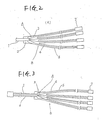
- Fig. 2 shows a first embodiment of a branching portion of a tape core type coated optical fiber (hereinafter simply referred to an "optical fiber branching portion") A.
- the optical fiber branching portion shown in Fig. 2 is provided with a tape core type coated fiber 1, a fixing portion 2 for fixing the tape core type coated fiber 1, a branch housing space 3, a single fiber 4, a single-fiber protecting sheath 5, an optical connector 7, and a multi-branch pipe B.
- Fig. 3 shows a second embodiment of a branching portion of a tape core type coated optical fiber according to the present invention, in which the tape core type coated fiber 1 is not fixed by the fixing portion instead the fiber 1 is housed in a protecting member 6 such as a tube or the like.
- Fig. 4A is a principle view of the multi-branch pipe B employed in the first embodiment shown in Fig. 2, which pipe comprises the single-fiber protecting sheath 5, the tape core type coated fiber fixing portion 2, and the branch housing space 3.
- Figs. 4B and 4C are cross sectional views showing arrangements of the configuration of single-fiber protecting sheath 5. That is, four protecting sheaths 5 form in a line in the arrangement of Fig. 4B, and in two lines and two columns in the arrangement of Fig. 4C.
- Figs. 5A and 5B show an example of a method of assembling the multi-branch pipe B arranged such that tubes 9 are inserted into a porous box 8 opened at its one side and a cover 10 is provided for covering the open side of the porous box 8.
- Figs. 5A and 5B are a plan view and a side view of the example, respectively.
- Fig. 6 is a sectional view showing the multi-branch pipe B employed in the second embodiment shown in Fig. 3, in which there is provided the tape core type coated fiber protecting member 6, a branch housing space 3, and a single-fiber protecting sheath 5.
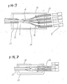
- Fig. 7 is a sectional view showing an example of an optical fiber cord applied to a branching portion of a tape core type coated fiber according to the present invention.
- the optical fiber cord shown in Fig. 7 has a configuration in which each of a tape core type coated fiber 1 and single fibers 4 is coated with a protecting sheath 13 containing therein a reinforcing member 12. An end of the protecting sheath 13 together with the multi-branch pipe B is contained in the reinforcing housing 17 filled with a resin 16.
- reinforcing housing 17 is pipe-like in Fig. 7, it is applicable to facilitate assembling of the inside by such a configuration that the reinforcing housing 17 is replaced by an one-side opening lunch box type reinforcing box 18 provided with a cover 10 as shown in Fig. 8.
- the tape core type coated fiber branching portion A shown in Fig. 2 is configured such that the tape core type coated fiber 1 branched at its forward end into single fibers is inserted from the tape core type coated fiber fixing portion 2 of the multi-branch pipe B shown in Fig. 4A into the protecting sheath 5 of the branching single fibers 4, and the tape core type coated fiber 1 is fixed at the tape core type coated fiber fixing portion 2, so that the branching portion A can be assembled without giving excessive force to the single fibers 4.
- branching portion A shown in Fig. 3 can be housed in the branching portion housing space 3 without fixing the tape core type coated fiber 1 at the branching portion A as shown in Fig. 6.
- the freedom of the tape core type coated fiber increases and the light transmission loss can sufficiently be minimized.
- optical fiber cord branching portion shown in Fig. 7 has a configuration in which the tape core type coated fiber branch portions made as described above are coated with the respective sheaths 13 and the reinforcing housing 17, and then the resin 16 is filled in the reinforcing housing 17. Accordingly, the resin 16 never directly touches the single fibers 4.
- optical fiber cord branching portion shown in Fig. 8 is similar in advantage to that shown in Fig. 7.
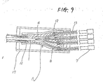
- Fig. 9 shows another arrangement of the optical fiber cord branching portion according to the invention.
- This arrangement is similar to the arrangement shown in Fig. 7.
- the reinforcing housing 17 is not filled with a resin.
- the branching portion of the optical fiber cord, an end part of the tape and an end part of each of the sheath 13 are fixedly covered with a heat-shrinkable tubing 19.
- This arrangement is advantageous in that the manufacturing time is shortened relative to the case in which a resin is filled in the housing 17.
- a heat-melting adhesion may be applied to the inner periphery of the heat-shrinkable tubing 19 thereby firmly fixing the branching portion, end part of the tape and end part of the sheath to one another.
- the multi-branch pipe has four branches.
- the invention is not limited thereto or thereby. That is, the multi-branch pipe may have a plurality of branches other than four.
- the single fibers branching from an end of the tape core type coated fiber never touch directly the adhesive or resin, so that stress is never exerted onto the optical fibers in the process of hardening the resin or adhesive, and the light transmission loss never increases in the manufacturing process.
Abstract
Description
- The present invention relates generally to an optical fiber, and more particularly to a branching portion of a tape core type coated optical fiber which branches optical fiber bundle into single fibers at its end portion.
- There has been developed a conventional optical fiber cord as shown in Fig. 1. The conventional optical fiber cord shown in Fig. 1 is provided with a tape core type coated
fiber 1, a reinforcingmember 12, a reinforcingsheath 13, asingle fiber 4, a branchingportion protecting plate 15, a reinforcinghousing 17, aresin 16, and anoptical fiber connector 7. The tape core type coatedfiber 1 is adhered to the branchingportion protecting plate 15. - Further, there is another conventional coated optical fiber branching portion of a five-to-one fiber conversion cord shown in 1988-Spring National Meeting B-599 of the Institute of Electronics, Information and Communication Engineers of Japan.
- According to the conventional optical fiber cord shown in Fig. 1, the tape core type coated
fiber 1 branching on the branchingportion protecting plate 15 is provisionally fixed to the branchingportion protecting plate 15 through an adhesive, and then, each of the tape core type coatedfiber 1 and thesingle fibers 4 is coated with the reinforcingsheath 13, an end of thesheath 13 and the connection portion between the tape core type coatedfiber 1 and thesingle fibers 4 are covered with the reinforcinghousing 17, and theresin 16 is filled in the reinforcinghousing 17. Such an optical fiber cord would cause a drawback that stress is exerted onto the tape core type coatedfiber 1 and thesingle fibers 4 in filling the resin and in hardening the resin to thereby increase undesirable light transmission loss. - Further, the conventional optical fiber cord would suffer from a problem that the tape core type coated
fiber 1 and thesingle fibers 4 are subject to stress by thermal expansion of theresin 16 when an environmental temperature varies since they are molded with theresin 16, so that the light transmission loss may increase. - Moreover, there would be raised a further problem that the work for fixing the branching portion of the tape core type coated
fiber 1 to the protectingplate 15 is fine work and poor in workability and, therefore, the light transmission loss may increase if the setting is not well. - There has been a still further problem that since the branching portion has such a basic configuration as described above, it is necessary to provide the protecting
plate 15 when the tape core type coatedfiber 1 is branched into thesingle fibers 4, and it is impossible to provide a mere branching portion of thesingle fibers 4 of the tape core type coatedfiber 1. - In view of the above-noted drawbacks and problems accompanying the conventional device, an object of the present invention is to provide a branching portion of a tape core type coated fiber, in which the single fibers branching from the tape core type coated fiber do not directly touch an adhesive or resin, no stress is exerted on the optical fibers in the process of hardening the adhesive or resin, no stress is exerted on the optical fibers even when the resin or the like is thermally expanded in use due to a change in an environmental temperature, and the light transmission loss does not increase.
- The foregoing and other objects have been achieved by the provision of a branching portion of a tape core type coated optical fiber according to the present invention described in detail hereinbelow.
-
- Fig. 1 is a sectional view showing a conventional optical fiber cord;
- Fig. 2 is a sectional view of an optical fiber branching portion according to a first embodiment of the present invention;
- Fig. 3 is a view showing an optical fiber branching portion according to a second embodiment of the invention;
- Fig. 4A is a view showing a multi-branch pipe for forming the branching portion of Fig. 2;
- Figs. 4B and 4C are cross sectional views showing two arrangements of a configuration of a multi branch pipe;
- Fig. 5A is a plan view of a multi-branch pipe arrangement different from that of Fig. 4A;
- Fig. 5B is a side view of the multi-branch pipe arrangement shown in Fig. 5B;
- Fig. 6 is a view showing a multi-branch pipe for forming branching portion of Fig. 3;
- Fig. 7 is a sectional view showing an optical fiber cord applied to the present invention; and
- Fig. 8 is a sectional view showing another optical fiber cord applied to the present invention.
- Fig. 9 is a sectional view showing another arrangement of the optical fiber cord according to the invention.
- The branching portion of the tape core type coated optical fiber of the present invention will now be described with reference to accompanying drawings.
- Fig. 2 shows a first embodiment of a branching portion of a tape core type coated optical fiber (hereinafter simply referred to an "optical fiber branching portion") A. The optical fiber branching portion shown in Fig. 2 is provided with a tape core type coated
fiber 1, afixing portion 2 for fixing the tape core type coatedfiber 1, abranch housing space 3, asingle fiber 4, a single-fiber protectingsheath 5, anoptical connector 7, and a multi-branch pipe B. - Fig. 3 shows a second embodiment of a branching portion of a tape core type coated optical fiber according to the present invention, in which the tape core type coated
fiber 1 is not fixed by the fixing portion instead thefiber 1 is housed in a protectingmember 6 such as a tube or the like. - Referring to Figs. 4 through 6, the above-mentioned multi-branch pipe B will be described.
- Fig. 4A is a principle view of the multi-branch pipe B employed in the first embodiment shown in Fig. 2, which pipe comprises the single-fiber protecting
sheath 5, the tape core type coatedfiber fixing portion 2, and thebranch housing space 3. Figs. 4B and 4C are cross sectional views showing arrangements of the configuration of single-fiber protectingsheath 5. That is, four protectingsheaths 5 form in a line in the arrangement of Fig. 4B, and in two lines and two columns in the arrangement of Fig. 4C. - Figs. 5A and 5B show an example of a method of assembling the multi-branch pipe B arranged such that
tubes 9 are inserted into a porous box 8 opened at its one side and acover 10 is provided for covering the open side of the porous box 8. Figs. 5A and 5B are a plan view and a side view of the example, respectively. - Fig. 6 is a sectional view showing the multi-branch pipe B employed in the second embodiment shown in Fig. 3, in which there is provided the tape core type coated
fiber protecting member 6, abranch housing space 3, and a single-fiber protectingsheath 5. - Fig. 7 is a sectional view showing an example of an optical fiber cord applied to a branching portion of a tape core type coated fiber according to the present invention. The optical fiber cord shown in Fig. 7 has a configuration in which each of a tape core type coated
fiber 1 andsingle fibers 4 is coated with a protectingsheath 13 containing therein a reinforcingmember 12. An end of the protectingsheath 13 together with the multi-branch pipe B is contained in the reinforcinghousing 17 filled with aresin 16. - Although the reinforcing
housing 17 is pipe-like in Fig. 7, it is applicable to facilitate assembling of the inside by such a configuration that the reinforcinghousing 17 is replaced by an one-side opening lunch boxtype reinforcing box 18 provided with acover 10 as shown in Fig. 8. - The tape core type coated fiber branching portion A shown in Fig. 2 is configured such that the tape core type coated
fiber 1 branched at its forward end into single fibers is inserted from the tape core type coatedfiber fixing portion 2 of the multi-branch pipe B shown in Fig. 4A into the protectingsheath 5 of the branchingsingle fibers 4, and the tape core type coatedfiber 1 is fixed at the tape core type coatedfiber fixing portion 2, so that the branching portion A can be assembled without giving excessive force to thesingle fibers 4. - Further, the branching portion A shown in Fig. 3 can be housed in the branching
portion housing space 3 without fixing the tape core type coatedfiber 1 at the branching portion A as shown in Fig. 6. Thus, the freedom of the tape core type coated fiber increases and the light transmission loss can sufficiently be minimized. - Further, the optical fiber cord branching portion shown in Fig. 7 has a configuration in which the tape core type coated fiber branch portions made as described above are coated with the
respective sheaths 13 and the reinforcinghousing 17, and then theresin 16 is filled in the reinforcinghousing 17. Accordingly, theresin 16 never directly touches thesingle fibers 4. - The optical fiber cord branching portion shown in Fig. 8 is similar in advantage to that shown in Fig. 7.
- Fig. 9 shows another arrangement of the optical fiber cord branching portion according to the invention. This arrangement is similar to the arrangement shown in Fig. 7. However, in this arrangement, the reinforcing
housing 17 is not filled with a resin. Instead, the branching portion of the optical fiber cord, an end part of the tape and an end part of each of thesheath 13 are fixedly covered with a heat-shrinkable tubing 19. This arrangement is advantageous in that the manufacturing time is shortened relative to the case in which a resin is filled in thehousing 17. A heat-melting adhesion may be applied to the inner periphery of the heat-shrinkable tubing 19 thereby firmly fixing the branching portion, end part of the tape and end part of the sheath to one another. - In the above-described embodiments, the multi-branch pipe has four branches. However, the invention is not limited thereto or thereby. That is, the multi-branch pipe may have a plurality of branches other than four.
- As described above, according to the present invention, the single fibers branching from an end of the tape core type coated fiber never touch directly the adhesive or resin, so that stress is never exerted onto the optical fibers in the process of hardening the resin or adhesive, and the light transmission loss never increases in the manufacturing process.
Claims (19)
means for housing said tape core type coated optical fiber, the tape core type coated optical fiber branches into a plurality of single fibers inside said housing means, said housing means comprising a plurality of branches through which each of said single fiber passes.
Applications Claiming Priority (2)
| Application Number | Priority Date | Filing Date | Title |
|---|---|---|---|
| JP63208667A JPH0797164B2 (en) | 1988-08-23 | 1988-08-23 | Branch of optical fiber ribbon |
| JP208667/88 | 1988-08-23 |
Publications (3)
| Publication Number | Publication Date |
|---|---|
| EP0355639A2 true EP0355639A2 (en) | 1990-02-28 |
| EP0355639A3 EP0355639A3 (en) | 1991-04-24 |
| EP0355639B1 EP0355639B1 (en) | 1994-11-02 |
Family
ID=16560059
Family Applications (1)
| Application Number | Title | Priority Date | Filing Date |
|---|---|---|---|
| EP89114966A Expired - Lifetime EP0355639B1 (en) | 1988-08-23 | 1989-08-11 | Tape core type coated optical fiber |
Country Status (4)
| Country | Link |
|---|---|
| US (1) | US4976508A (en) |
| EP (1) | EP0355639B1 (en) |
| JP (1) | JPH0797164B2 (en) |
| DE (1) | DE68919164T2 (en) |
Cited By (23)
| Publication number | Priority date | Publication date | Assignee | Title |
|---|---|---|---|---|
| EP0579357A1 (en) * | 1992-05-15 | 1994-01-19 | Andrew John Neave | A light distribution unit for use with a light projector which projects light via light guides |
| WO1994020872A1 (en) * | 1993-03-04 | 1994-09-15 | Siemens Aktiengesellschaft | Optical connecting cable |
| EP0617305A1 (en) * | 1993-03-26 | 1994-09-28 | Corning Incorporated | Cassette for an optical fiber device, equipped with a bundle of flexible tubes protecting the fibers |
| EP0646811A2 (en) * | 1993-10-01 | 1995-04-05 | BICC Public Limited Company | Breakout for optical fibres |
| WO1995015509A1 (en) * | 1993-12-02 | 1995-06-08 | Siemens Aktiengesellschaft | Connecting device and branching device for optical fibre cables |
| EP0903594A1 (en) * | 1997-09-18 | 1999-03-24 | PIRELLI CAVI E SISTEMI S.p.A. | Method for performing fixing inside a container for optical connection components |
| US6269212B1 (en) | 1997-09-18 | 2001-07-31 | Pirelli Cavi E Sistemi S.P.A. | Method for performing fixing inside a container for optical connection components |
| EP1168016A2 (en) * | 2000-06-23 | 2002-01-02 | Molex Incorporated | Fiber optic connector |
| EP1180706A1 (en) * | 2000-08-14 | 2002-02-20 | Dätwyler Ag Schweizerische Kabel-, Gummi- Und Kunststoffwerke | Prefabricated optical cable and method for prefabricating an optical cable |
| EP1245980A2 (en) * | 2001-03-28 | 2002-10-02 | Corning Cable Systems LLC | Furcation kit for optical fiber cable |
| WO2003048830A2 (en) * | 2001-12-04 | 2003-06-12 | Molex Incorporated | Fanout system or apparatus for a fiber optic cable and including a method of fabricating same |
| EP1361465A1 (en) | 2002-05-07 | 2003-11-12 | Corning Cable Systems LLC | High performance, flexible optical fiber furcation |
| WO2009150011A1 (en) * | 2008-06-10 | 2009-12-17 | Tyco Electronics Nederland Bv | Fiber optic furcation assembly |
| US7689089B2 (en) | 2006-10-11 | 2010-03-30 | Panduit Corp. | Release latch for pre-terminated cassette |
| DE102008062535A1 (en) * | 2008-12-16 | 2010-06-17 | Adc Gmbh | Micro-distribution cables for optical communication technology and method for producing a micro-distribution cable |
| US8573855B2 (en) | 2008-10-06 | 2013-11-05 | Adc Telecommunications, Inc. | Fanout cable assembly and method |
| WO2016078708A1 (en) * | 2014-11-20 | 2016-05-26 | Prysmian S.P.A. | Device for connecting an optical cable and a protective tube |
| US10514520B2 (en) | 2014-10-27 | 2019-12-24 | Commscope Technologies Llc | Fiber optic cable with flexible conduit |
| US10606019B2 (en) | 2015-07-31 | 2020-03-31 | Commscope Technologies Australia Pty Ltd | Cable breakout assembly |
| US10890730B2 (en) | 2016-08-31 | 2021-01-12 | Commscope Technologies Llc | Fiber optic cable clamp and clamp assembly |
| US10914909B2 (en) | 2016-10-13 | 2021-02-09 | Commscope Technologies Llc | Fiber optic breakout transition assembly incorporating epoxy plug and cable strain relief |
| US11131822B2 (en) | 2017-05-08 | 2021-09-28 | Commscope Technologies Llc | Fiber-optic breakout transition assembly |
| US11131821B2 (en) | 2016-03-18 | 2021-09-28 | Commscope Technologies Llc | Optic fiber cable fanout conduit arrangements; components, and methods |
Families Citing this family (20)
| Publication number | Priority date | Publication date | Assignee | Title |
|---|---|---|---|---|
| US5048918A (en) * | 1990-02-07 | 1991-09-17 | Raychem Corporation | Optical fiber cable termination |
| FR2658308B1 (en) * | 1990-02-09 | 1993-04-09 | Alcatel Cable | JUNCTION BOX FOR OPTICAL FIBER CABLE, AND MOUNTING METHOD THEREOF. |
| US5073044A (en) * | 1990-10-31 | 1991-12-17 | Amp Incorporated | Right angle strain relief for optical fiber connector |
| US5185840A (en) * | 1991-05-06 | 1993-02-09 | Computer Crafts, Inc. | Branching method for a multi-fiber fiberoptic cable |
| JPH04350801A (en) * | 1991-05-29 | 1992-12-04 | Furukawa Electric Co Ltd:The | Branch part of multi-unit coated optical fiber |
| US5231688A (en) * | 1991-10-07 | 1993-07-27 | Siecor Corporation | Furcation kit |
| US5892870A (en) * | 1995-11-16 | 1999-04-06 | Fiber Connections Inc. | Fibre optic cable connector |
| US6614972B1 (en) | 1998-12-02 | 2003-09-02 | 3M Innovative Properties Company | Coupler for transporting and distributing light to multiple locations with uniform color and intensity |
| US6618530B1 (en) | 1998-12-02 | 2003-09-09 | 3M Innovative Properties Company | Apparatus for transporting and distributing light using multiple light fibers |
| US8995106B2 (en) | 2011-02-08 | 2015-03-31 | Raycap, S.A. | Overvoltage protection system for wireless communication systems |
| US11251608B2 (en) | 2010-07-13 | 2022-02-15 | Raycap S.A. | Overvoltage protection system for wireless communication systems |
| US9099860B2 (en) | 2012-12-10 | 2015-08-04 | Raycap Intellectual Property Ltd. | Overvoltage protection and monitoring system |
| US9640986B2 (en) | 2013-10-23 | 2017-05-02 | Raycap Intellectual Property Ltd. | Cable breakout assembly |
| US9575277B2 (en) | 2015-01-15 | 2017-02-21 | Raycap, S.A. | Fiber optic cable breakout assembly |
| US10802237B2 (en) | 2015-11-03 | 2020-10-13 | Raycap S.A. | Fiber optic cable management system |
| US9971119B2 (en) | 2015-11-03 | 2018-05-15 | Raycap Intellectual Property Ltd. | Modular fiber optic cable splitter |
| WO2018136812A1 (en) | 2017-01-20 | 2018-07-26 | Raycap S.A. | Power transmission system for wireless communication systems |
| CN107167887B (en) * | 2017-05-16 | 2019-06-11 | 深圳长飞智连技术有限公司 | A kind of polarity management method of wildcard fiber optic tap module |
| US10971928B2 (en) | 2018-08-28 | 2021-04-06 | Raycap Ip Assets Ltd | Integrated overvoltage protection and monitoring system |
| US11677164B2 (en) | 2019-09-25 | 2023-06-13 | Raycap Ip Assets Ltd | Hybrid antenna distribution unit |
Citations (5)
| Publication number | Priority date | Publication date | Assignee | Title |
|---|---|---|---|---|
| FR2331041A1 (en) * | 1975-11-05 | 1977-06-03 | Fort Francois | Optical cables connector tubes - are precision machined and their ends are polished and they are held in plastics plate |
| JPS56165104A (en) * | 1980-05-24 | 1981-12-18 | Nippon Telegr & Teleph Corp <Ntt> | Cable termination construction in anchor device of marine optical communication cable |
| US4364788A (en) * | 1979-12-17 | 1982-12-21 | Western Electric Company, Inc. | Method of forming a fiber ribbon cable unit |
| JPS58166311A (en) * | 1982-03-26 | 1983-10-01 | Fujitsu Ltd | Optical fiber converting case |
| FR2587126A1 (en) * | 1985-09-09 | 1987-03-13 | Lignes Telegraph Telephon | Device for breaking out a fibre-optic bundle into single optical fibres |
Family Cites Families (7)
| Publication number | Priority date | Publication date | Assignee | Title |
|---|---|---|---|---|
| DE3024310C2 (en) * | 1980-06-27 | 1983-06-23 | Siemens AG, 1000 Berlin und 8000 München | Optical cable and process for its manufacture |
| WO1984000216A1 (en) * | 1982-07-05 | 1984-01-19 | Furukawa Electric Co Ltd | Coated optical fiber |
| JPS61144611A (en) * | 1984-12-19 | 1986-07-02 | Ube Nitto Kasei Kk | Reinforced optical fiber and its production |
| US4767183A (en) * | 1986-05-12 | 1988-08-30 | Westinghouse Electric Corp. | High strength, heavy walled cable construction |
| US4840454A (en) * | 1986-09-02 | 1989-06-20 | Siemens Aktiengesellschat | Optical cable and method of manufacturing |
| US4744622A (en) * | 1986-09-12 | 1988-05-17 | Amp Incorporated | Optical fiber splice case |
| FR2622024B1 (en) * | 1987-10-16 | 1990-01-19 | Comp Generale Electricite | METHOD OF MANUFACTURING A CABLE WITH OPTICAL FIBER AND CABLE OBTAINED BY THIS METHOD |
-
1988
- 1988-08-23 JP JP63208667A patent/JPH0797164B2/en not_active Expired - Fee Related
-
1989
- 1989-08-11 DE DE68919164T patent/DE68919164T2/en not_active Expired - Fee Related
- 1989-08-11 EP EP89114966A patent/EP0355639B1/en not_active Expired - Lifetime
- 1989-08-15 US US07/393,938 patent/US4976508A/en not_active Expired - Lifetime
Patent Citations (5)
| Publication number | Priority date | Publication date | Assignee | Title |
|---|---|---|---|---|
| FR2331041A1 (en) * | 1975-11-05 | 1977-06-03 | Fort Francois | Optical cables connector tubes - are precision machined and their ends are polished and they are held in plastics plate |
| US4364788A (en) * | 1979-12-17 | 1982-12-21 | Western Electric Company, Inc. | Method of forming a fiber ribbon cable unit |
| JPS56165104A (en) * | 1980-05-24 | 1981-12-18 | Nippon Telegr & Teleph Corp <Ntt> | Cable termination construction in anchor device of marine optical communication cable |
| JPS58166311A (en) * | 1982-03-26 | 1983-10-01 | Fujitsu Ltd | Optical fiber converting case |
| FR2587126A1 (en) * | 1985-09-09 | 1987-03-13 | Lignes Telegraph Telephon | Device for breaking out a fibre-optic bundle into single optical fibres |
Non-Patent Citations (3)
| Title |
|---|
| PATENT ABSTRACTS OF JAPAN, vol. 6, no. 51 (P-108)[929], 6th April 1982; & JP-A-56 165 104 (NIPPON DENSHIN) 18-12-1981 * |
| PATENT ABSTRACTS OF JAPAN, vol. 8, no. 1 (P-246)[1438], 6th January 1984; & JP-A-58 166 311 (FUJITSU) 01-10-1983 * |
| THE TRANSACTIONS OF THE I.E.C.E. OF JAPAN/SECTION E, vol. E-70, no. 4, April 1987, pages 276-277, Tokyo, JP; S. NAGASAWA et al.: "Structural design of optical-fiber fanout connector for fiber-ribbon cable termination" * |
Cited By (41)
| Publication number | Priority date | Publication date | Assignee | Title |
|---|---|---|---|---|
| EP0579357A1 (en) * | 1992-05-15 | 1994-01-19 | Andrew John Neave | A light distribution unit for use with a light projector which projects light via light guides |
| WO1994020872A1 (en) * | 1993-03-04 | 1994-09-15 | Siemens Aktiengesellschaft | Optical connecting cable |
| EP0617305A1 (en) * | 1993-03-26 | 1994-09-28 | Corning Incorporated | Cassette for an optical fiber device, equipped with a bundle of flexible tubes protecting the fibers |
| FR2703160A1 (en) * | 1993-03-26 | 1994-09-30 | Corning Inc | Cassette for fiber optic device, equipped with a bundle of flexible tubes for protecting the fibers. |
| US5438641A (en) * | 1993-03-26 | 1995-08-01 | Corning Incorporated | Optical fiber component cassette with pigtail tube assembly |
| EP0646811A2 (en) * | 1993-10-01 | 1995-04-05 | BICC Public Limited Company | Breakout for optical fibres |
| EP0646811A3 (en) * | 1993-10-01 | 1995-12-27 | Bicc Plc | Breakout for optical fibres. |
| WO1995015509A1 (en) * | 1993-12-02 | 1995-06-08 | Siemens Aktiengesellschaft | Connecting device and branching device for optical fibre cables |
| EP0903594A1 (en) * | 1997-09-18 | 1999-03-24 | PIRELLI CAVI E SISTEMI S.p.A. | Method for performing fixing inside a container for optical connection components |
| US6269212B1 (en) | 1997-09-18 | 2001-07-31 | Pirelli Cavi E Sistemi S.P.A. | Method for performing fixing inside a container for optical connection components |
| EP1168016A2 (en) * | 2000-06-23 | 2002-01-02 | Molex Incorporated | Fiber optic connector |
| EP1168016A3 (en) * | 2000-06-23 | 2005-04-27 | Molex Incorporated | Fiber optic connector |
| EP1180706A1 (en) * | 2000-08-14 | 2002-02-20 | Dätwyler Ag Schweizerische Kabel-, Gummi- Und Kunststoffwerke | Prefabricated optical cable and method for prefabricating an optical cable |
| EP1245980A2 (en) * | 2001-03-28 | 2002-10-02 | Corning Cable Systems LLC | Furcation kit for optical fiber cable |
| EP1245980B1 (en) * | 2001-03-28 | 2006-06-14 | Corning Cable Systems LLC | Furcation kit for optical fiber cable |
| WO2003048830A2 (en) * | 2001-12-04 | 2003-06-12 | Molex Incorporated | Fanout system or apparatus for a fiber optic cable and including a method of fabricating same |
| WO2003048830A3 (en) * | 2001-12-04 | 2003-12-04 | Molex Inc | Fanout system or apparatus for a fiber optic cable and including a method of fabricating same |
| CN1294434C (en) * | 2001-12-04 | 2007-01-10 | 莫列斯公司 | Fanout system or apparatus for a fiber optic cable and including a method of fabricating same |
| EP1361465A1 (en) | 2002-05-07 | 2003-11-12 | Corning Cable Systems LLC | High performance, flexible optical fiber furcation |
| US6771861B2 (en) | 2002-05-07 | 2004-08-03 | Corning Cable Systems Llc | High performance, flexible optical fiber furcation |
| US7962000B2 (en) | 2006-10-11 | 2011-06-14 | Panduit Corp. | Release latch for pre-terminated cassette |
| US7689089B2 (en) | 2006-10-11 | 2010-03-30 | Panduit Corp. | Release latch for pre-terminated cassette |
| US8346046B2 (en) | 2006-10-11 | 2013-01-01 | Panduit Corp. | Release latch for pre-terminated cassette |
| WO2009150011A1 (en) * | 2008-06-10 | 2009-12-17 | Tyco Electronics Nederland Bv | Fiber optic furcation assembly |
| JP2011523101A (en) * | 2008-06-10 | 2011-08-04 | タイコ エレクトロニクス ネーデルランド ビーヴイ | Optical fiber branch assembly |
| US8571367B2 (en) | 2008-06-10 | 2013-10-29 | Tyco Electronics Nederland Bv | Fiber optic furcation assembly |
| CN102057310B (en) * | 2008-06-10 | 2014-11-19 | 泰科电子荷兰公司 | Fiber optic furcation assembly |
| US8573855B2 (en) | 2008-10-06 | 2013-11-05 | Adc Telecommunications, Inc. | Fanout cable assembly and method |
| DE102008062535A1 (en) * | 2008-12-16 | 2010-06-17 | Adc Gmbh | Micro-distribution cables for optical communication technology and method for producing a micro-distribution cable |
| WO2010072286A1 (en) * | 2008-12-16 | 2010-07-01 | Adc Gmbh | Micro-distribution cable for optical communications and method for producing a micro-distribution cable |
| US10514520B2 (en) | 2014-10-27 | 2019-12-24 | Commscope Technologies Llc | Fiber optic cable with flexible conduit |
| US11543613B2 (en) | 2014-10-27 | 2023-01-03 | Commscope Technologies Llc | Fiber optic cable with flexible conduit |
| AU2014411737B2 (en) * | 2014-11-20 | 2021-01-28 | Prysmian S.P.A. | Device for connecting an optical cable and a protective tube |
| WO2016078708A1 (en) * | 2014-11-20 | 2016-05-26 | Prysmian S.P.A. | Device for connecting an optical cable and a protective tube |
| US10606019B2 (en) | 2015-07-31 | 2020-03-31 | Commscope Technologies Australia Pty Ltd | Cable breakout assembly |
| US11131821B2 (en) | 2016-03-18 | 2021-09-28 | Commscope Technologies Llc | Optic fiber cable fanout conduit arrangements; components, and methods |
| US11372188B2 (en) | 2016-08-31 | 2022-06-28 | Commscope Technologies Llc | Fiber optic cable clamp and clamp assembly |
| US10890730B2 (en) | 2016-08-31 | 2021-01-12 | Commscope Technologies Llc | Fiber optic cable clamp and clamp assembly |
| US10914909B2 (en) | 2016-10-13 | 2021-02-09 | Commscope Technologies Llc | Fiber optic breakout transition assembly incorporating epoxy plug and cable strain relief |
| US11579394B2 (en) | 2016-10-13 | 2023-02-14 | Commscope Technologies Llc | Fiber optic breakout transition assembly incorporating epoxy plug and cable strain relief |
| US11131822B2 (en) | 2017-05-08 | 2021-09-28 | Commscope Technologies Llc | Fiber-optic breakout transition assembly |
Also Published As
| Publication number | Publication date |
|---|---|
| JPH0797164B2 (en) | 1995-10-18 |
| US4976508A (en) | 1990-12-11 |
| DE68919164T2 (en) | 1995-03-09 |
| EP0355639B1 (en) | 1994-11-02 |
| DE68919164D1 (en) | 1994-12-08 |
| JPH0256505A (en) | 1990-02-26 |
| EP0355639A3 (en) | 1991-04-24 |
Similar Documents
| Publication | Publication Date | Title |
|---|---|---|
| US4976508A (en) | Tape core type coated optical fiber | |
| USRE49374E1 (en) | Fiber optic cable and furcation module | |
| US5970195A (en) | Fiber optic cable furcation unit | |
| US4465335A (en) | Concentric core optical fiber coupler | |
| US6909833B2 (en) | Optical fiber enclosure system using integrated optical connector and coupler assembly | |
| US6614971B2 (en) | Fanout system or apparatus for a fiber optic cable and including a method of fabricating same | |
| US5838861A (en) | Transition assembly for optical fiber | |
| US5905835A (en) | Optical fiber multi-ribbon | |
| US4989945A (en) | Branch device for multi-core optical fiber | |
| CA2074860A1 (en) | Method of reinforcing optical fiber coupler | |
| US5727102A (en) | Multifiber optical connector for optical ribbon cable | |
| US6676299B1 (en) | Device having multiple optical fibers | |
| US5425831A (en) | Optical fiber connecting method | |
| US4123138A (en) | Optical fiber connector | |
| US7093984B2 (en) | Anchor for fiber optic cable | |
| JP2000298219A (en) | Awg module | |
| US6226435B1 (en) | Bulbous configured fiber optic splice closure and associated methods | |
| JP2002267881A (en) | Optical fiber-branched coated optical fiber with multi- fiber optical connector | |
| EP1680698B1 (en) | Anchor for fiber optic cable | |
| US6047097A (en) | Optical coupler | |
| JPH01234805A (en) | Method of fixing fiber to fiber bender and optical tapping device | |
| CA2114691C (en) | Reinforced multicore optical fiber coupler | |
| JP2661960B2 (en) | Multi-core optical cord branch | |
| JPH0641204Y2 (en) | Optical repeater terminal optical fiber storage structure | |
| JPH02129605A (en) | Reinforced accommodating structure for optical fiber connection part |
Legal Events
| Date | Code | Title | Description |
|---|---|---|---|
| PUAI | Public reference made under article 153(3) epc to a published international application that has entered the european phase |
Free format text: ORIGINAL CODE: 0009012 |
|
| AK | Designated contracting states |
Kind code of ref document: A2 Designated state(s): DE GB IT |
|
| 17P | Request for examination filed |
Effective date: 19901220 |
|
| PUAL | Search report despatched |
Free format text: ORIGINAL CODE: 0009013 |
|
| AK | Designated contracting states |
Kind code of ref document: A3 Designated state(s): DE GB IT |
|
| 17Q | First examination report despatched |
Effective date: 19920714 |
|
| GRAA | (expected) grant |
Free format text: ORIGINAL CODE: 0009210 |
|
| AK | Designated contracting states |
Kind code of ref document: B1 Designated state(s): DE GB IT |
|
| REF | Corresponds to: |
Ref document number: 68919164 Country of ref document: DE Date of ref document: 19941208 |
|
| ITF | It: translation for a ep patent filed |
Owner name: SOCIETA' ITALIANA BREVETTI S.P.A. |
|
| PLBE | No opposition filed within time limit |
Free format text: ORIGINAL CODE: 0009261 |
|
| STAA | Information on the status of an ep patent application or granted ep patent |
Free format text: STATUS: NO OPPOSITION FILED WITHIN TIME LIMIT |
|
| 26N | No opposition filed | ||
| REG | Reference to a national code |
Ref country code: GB Ref legal event code: IF02 |
|
| PGFP | Annual fee paid to national office [announced via postgrant information from national office to epo] |
Ref country code: GB Payment date: 20020807 Year of fee payment: 14 |
|
| PGFP | Annual fee paid to national office [announced via postgrant information from national office to epo] |
Ref country code: DE Payment date: 20020816 Year of fee payment: 14 |
|
| PG25 | Lapsed in a contracting state [announced via postgrant information from national office to epo] |
Ref country code: GB Free format text: LAPSE BECAUSE OF NON-PAYMENT OF DUE FEES Effective date: 20030811 |
|
| PG25 | Lapsed in a contracting state [announced via postgrant information from national office to epo] |
Ref country code: DE Free format text: LAPSE BECAUSE OF NON-PAYMENT OF DUE FEES Effective date: 20040302 |
|
| GBPC | Gb: european patent ceased through non-payment of renewal fee |
Effective date: 20030811 |
|
| PG25 | Lapsed in a contracting state [announced via postgrant information from national office to epo] |
Ref country code: IT Free format text: LAPSE BECAUSE OF NON-PAYMENT OF DUE FEES Effective date: 20050811 |