EP0357343A2 - Method and apparatus for protecting electrical equipment - Google Patents
Method and apparatus for protecting electrical equipment Download PDFInfo
- Publication number
- EP0357343A2 EP0357343A2 EP89308612A EP89308612A EP0357343A2 EP 0357343 A2 EP0357343 A2 EP 0357343A2 EP 89308612 A EP89308612 A EP 89308612A EP 89308612 A EP89308612 A EP 89308612A EP 0357343 A2 EP0357343 A2 EP 0357343A2
- Authority
- EP
- European Patent Office
- Prior art keywords
- level
- input signal
- equipment
- detection means
- electromagnetic interference
- Prior art date
- Legal status (The legal status is an assumption and is not a legal conclusion. Google has not performed a legal analysis and makes no representation as to the accuracy of the status listed.)
- Withdrawn
Links
Images

Classifications
-
- G—PHYSICS
- G08—SIGNALLING
- G08B—SIGNALLING OR CALLING SYSTEMS; ORDER TELEGRAPHS; ALARM SYSTEMS
- G08B29/00—Checking or monitoring of signalling or alarm systems; Prevention or correction of operating errors, e.g. preventing unauthorised operation
- G08B29/18—Prevention or correction of operating errors
- G08B29/185—Signal analysis techniques for reducing or preventing false alarms or for enhancing the reliability of the system
Definitions
- This invention relates to a method and apparatus for preventing electrical and electronic equipment from reacting falsely to the effects of electromagnetic interference.
- a familiar example of this phenomenon may occur in a home burglar alarm.
- surges may be induced in the mains supply lines and in the burglar alarm signal or sensor lines.
- the alarm may react in the same way as it reacts when disturbed by an intruder, by going into an alarm mode. A series of such false alarms will reduce the effectiveness of the burglar alarm.
- the setting off of a burglar alarm will be interpreted as being caused by lightning rather than by an intruder, which may not always be the case.
- a false triggering caused by lightning or switching surges could have disastrous effects in the case of a factory fire alarm.
- a control room could be unnecessarily doused with carbon dioxide gas, for instance, or an overhead sprinkler system could be activated. This will occur in cases where lightning or switching surges create a false alarm condition.
- a method of protecting electronic or electrical equipment from electromagnetic interference including the steps of detecting the electromagnetic interference, generating an input signal representative of the interference, comparing the level of the input signal to a predetermined threshold level, and generating an output signal to initiate at least one protective measure in the event of the level of the input signal exceeding the predetermined threshold.
- Electromagnetic interference may be detected in at least one electrical supply conductor connected to the equipment, or may be detected by an independent antenna.
- the input signal may be filtered to reject frequency components thereof falling outside a predetermined frequency band.
- the predetermined frequency range may correspond, for example, to the electromagnetic frequency spectrum of lightning.
- the protective measure may comprise providing a reset signal to the equipment, or may comprise interrupting the power supply to the equipment for a predetermined period. or.
- apparatus for protecting electronic or electrical equipment from electromagnetic interference comprises detection means for detecting the electromagnetic interference and generating an input signal representative of the interference; level detection means for comparing the level of the input signal to a predetermined threshold level; and control means responsive to the level detection means for generating an output signal in the event of the level of the input signal exceeding the predetermined threshold.
- each main functional component of an electromagnetic interference circuit according to the invention is shown in block form.
- the detection means comprises a suitable antenna 1 which is intended to pick up electromagnetic interference.
- This may comprise a specially adapted antenna, or alternatively may be constituted by any power or signal lines of the apparatus to be protected, which perform the function of detecting electromagnetic interference.
- An input circuit 2 decouples and galvanically insulates the antenna 1 from the rest of the circuitry.
- the decoupled signal is then rectified in a rectification stage 3 so that both positive and negative excursions of the signal may be detected.
- the rectified signal is then fed to a frequency discrimination stage 4 and a level detection stage 5.
- the frequency discrimination stage 4 allows the circuitry to detect a specific source of interference, such as lightning, having a known or predicted interference frequency spectrum, and to discriminate between this source and another source having a different frequency or frequency spectrum, such as the 50Hz or 60Hz mains supply frequency.
- the function of frequency discrimination is performed by the combined action of the antenna 1, the input circuit 2, and further filtering means incorporated in the frequency discrimination stage 4.
- the level detection stage 5 performs the function of determining whether the magnitude of the interference signal exceeds a predetermined level, and if so, generates an output pulse which triggers timing means 6.
- Factors influencing the level of detection include the efficiency or gain of the antenna 1, the gain of the input and decoupling circuit 2 (if any) and the actual choice of the detection threshold of the level detector 5.
- the output pulse from the level detector 5 is converted to an output signal having a duration which is set by the timing means 6.
- the output signal in turn actuates switching means which are incorporated in an interface block 7.
- the interface block 7 provides a link between the protection circuit and the electrical or electronic apparatus requiring protection, and can also serve to isolate the protection circuit galvanically from the equipment it protects.
- the switching means resets the apparatus in the event of it being falsely triggered by lightning, or prevents the false triggering of the apparatus in the first place.
- the antenna means 1 comprises live and earth leads 10 and 11 which are connected to mains and earth lines, respectively, which power the electrical equipment (not shown) requiring protection. Electromagnetic interference occurring in or between the live and earth leads 10 and 11 will thus be detected.
- An extended signal lead can be used in place of the live lead 10, or an independent antenna having selected frequency response characteristics can be employed.
- the input circuit 2 comprises two decoupling capacitors 12 and a signal-type transformer 14.
- the capacitors 12 in conjunction with the transformer 14 provide galvanic isolation between the protection circuit and the outside world.
- a full-wave bridge rectifier 16 is coupled to the secondary of the transformer 14.
- the frequency discrimination means 4 is provided by low pass filters 20 located on either side of a zener diode 18.
- the low pass filters 20 are designed so that they primarily let through only signals having the frequency characteristics of lighting.
- the zener diode 18 has a selected threshold voltage and acts as the level detection stage 5. It has a voltage rating chosen to give the desired level of discrimination. Only input (interference) signals having a sufficiently high level will be passed by the zener diode to the following stages.
- the output signal from the filter 20 located after the zener diode 18 is fed into the base of a transistor 22.
- the transistor 22 provides a negative-going pulse to a timer 24, which provides an output signal having a predetermined time delay, set by an RC network.
- the output signal from the timer 24 passes through a light emitting diode 26.
- the light emitting diode 26 provides a visual indication of the period for which the timer holds its output signal on.
- a relay 28 is energised by the output signal from the timer.
- the relay actuates contacts 30.
- the contacts 30 are accessible to the user of the electrical of electronic equipment through output leads 32, and can be used in various ways.
- the contacts can be wired in series with the power supply to the equipment to be protected, for example, or can be connected to a reset or disable/enable input of the equipment.
- the switch 30 will operate to reset the alarm or to prevent the alarm from reacting to external stimuli for a time set by the timing device 24.
- the output signal of the timer can be applied directly to a reset input of the equipment.
- this output signal can be detected by hardware or software in computer-based equipment.
- the timing device 24 can be set to deliver an output signal for a time period equivalent to the maximum likely duration of electromagnetic interference caused by a lightning strike, for example.
- FIG. 3 shows an alternative, second embodiment of the interference prevention circuit.
- An antenna 110 is provided in the form of a pick-up wire which senses interference relative to a reference mains earth lead 112.
- the output of the antenna is connected via a decoupling capacitor 114 and a resistor 116 to a full wave rectifier bridge 118.
- the bridge output is connected to an opto-isolator 120.
- the decoupling function of the circuit is thus performed both by the capacitor 114 and the opto-isolator 120, which provide galvanic isolating between the circuit and the outside world.
- the frequency discrimination function of the circuit is performed by the RC high pass filter formed by the capacitor 114 and the resistor 116, and the high frequency cut-off of the opto-isolator 120.
- the output of the opto-isolator 120 is fed to the base of a transistor 122 via a pair of resistors 124 and 126.
- the values of these resistors, together with the value of the resistor 116, are selected to determine the discrimination threshold of the circuit, that is, the magnitude of the input signal which is required in order to turn the transistor 122 on.
- the transistor 122 When a sufficiently large input (interference) signal is detected, the transistor 122 turns on, and provides a negative going pulse to the trigger input of a timer 128.
- the timer 128 provides an output signal having a preset duration, which is determined by an RC network.
- the output of the timer is fed to a light emitting diode 130, which provides a visual indication of the period for which the timer holds its output signal on.
- a relay 132 is engergised, via a current limiting resistor 134, by the output of the timer 128, and operates contacts 136 which are, again, accessible to the user of the electrical or electronic equipment to be protected via output leads 138.
- the output signal of the timer 128 can be applied directly to the protected equipment as a reset signal. This is useful where speed is important, and where galvanic isolation is not required.
- the invention is not confined to alarm applications, but may be used to reset or protect any electronic or electrical equipment, such as computer installations, which may be affected by transient electromagnetic interference.
- the invention may also form part of a whole electrical protection scheme, incorporating additional circuitry. It will be understood that “protect” and “protection” are used in a broad sense in this specification, and it is intended to convey that the invention can provide protection against malfunctioning or error conditions, as well as protection against damage in certain cases.
Abstract
Description
- This invention relates to a method and apparatus for preventing electrical and electronic equipment from reacting falsely to the effects of electromagnetic interference.
- Electrical and electronic equipment is often affected by transient electromagnetic interference in communication and mains supply lines. Lightning and switching surges are prime examples of such interference. In many cases this will cause the malfunctioning of such equipment by creating a false alarm signal or condition to which it will respond.
- A familiar example of this phenomenon may occur in a home burglar alarm. In the event of a lightning strike in the vicinity, surges may be induced in the mains supply lines and in the burglar alarm signal or sensor lines. The alarm may react in the same way as it reacts when disturbed by an intruder, by going into an alarm mode. A series of such false alarms will reduce the effectiveness of the burglar alarm. In the event of stormy weather, for instance, the setting off of a burglar alarm will be interpreted as being caused by lightning rather than by an intruder, which may not always be the case.
- Likewise, a false triggering caused by lightning or switching surges could have disastrous effects in the case of a factory fire alarm. A control room could be unnecessarily doused with carbon dioxide gas, for instance, or an overhead sprinkler system could be activated. This will occur in cases where lightning or switching surges create a false alarm condition.
- The more often an alarm is falsely triggered the less effective it is in fulfilling its purpose.
- According to the invention there is provided a method of protecting electronic or electrical equipment from electromagnetic interference including the steps of detecting the electromagnetic interference, generating an input signal representative of the interference, comparing the level of the input signal to a predetermined threshold level, and generating an output signal to initiate at least one protective measure in the event of the level of the input signal exceeding the predetermined threshold.
- Electromagnetic interference may be detected in at least one electrical supply conductor connected to the equipment, or may be detected by an independent antenna.
- The input signal may be filtered to reject frequency components thereof falling outside a predetermined frequency band.
- The predetermined frequency range may correspond, for example, to the electromagnetic frequency spectrum of lightning.
- The protective measure may comprise providing a reset signal to the equipment, or may comprise interrupting the power supply to the equipment for a predetermined period. or.
- Further according to the invention, apparatus for protecting electronic or electrical equipment from electromagnetic interference comprises detection means for detecting the electromagnetic interference and generating an input signal representative of the interference; level detection means for comparing the level of the input signal to a predetermined threshold level; and control means responsive to the level detection means for generating an output signal in the event of the level of the input signal exceeding the predetermined threshold.
-
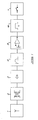
- Figure 1 shows a schematic diagram representing the main functional components of apparatus according to the invention in block form;
- Figure 2 shows a circuit diagram of a first embodiment of the invention; and
- Figure 3 illustrates a second embodiment of the invention.
- In Figure 1, each main functional component of an electromagnetic interference circuit according to the invention is shown in block form. The detection means comprises a
suitable antenna 1 which is intended to pick up electromagnetic interference. This may comprise a specially adapted antenna, or alternatively may be constituted by any power or signal lines of the apparatus to be protected, which perform the function of detecting electromagnetic interference. - An
input circuit 2 decouples and galvanically insulates theantenna 1 from the rest of the circuitry. The decoupled signal is then rectified in arectification stage 3 so that both positive and negative excursions of the signal may be detected. The rectified signal is then fed to afrequency discrimination stage 4 and a level detection stage 5. Thefrequency discrimination stage 4 allows the circuitry to detect a specific source of interference, such as lightning, having a known or predicted interference frequency spectrum, and to discriminate between this source and another source having a different frequency or frequency spectrum, such as the 50Hz or 60Hz mains supply frequency. The function of frequency discrimination is performed by the combined action of theantenna 1, theinput circuit 2, and further filtering means incorporated in thefrequency discrimination stage 4. - The level detection stage 5 performs the function of determining whether the magnitude of the interference signal exceeds a predetermined level, and if so, generates an output pulse which triggers timing means 6. Factors influencing the level of detection include the efficiency or gain of the
antenna 1, the gain of the input and decoupling circuit 2 (if any) and the actual choice of the detection threshold of the level detector 5. - The output pulse from the level detector 5 is converted to an output signal having a duration which is set by the timing means 6. The output signal in turn actuates switching means which are incorporated in an interface block 7. The interface block 7 provides a link between the protection circuit and the electrical or electronic apparatus requiring protection, and can also serve to isolate the protection circuit galvanically from the equipment it protects. The switching means resets the apparatus in the event of it being falsely triggered by lightning, or prevents the false triggering of the apparatus in the first place.
- Two specific embodiments of the apparatus described above will now be described. Referring to Figure 2, a circuit diagram embodying the functional blocks of Figure 1 is shown. The antenna means 1 comprises live and earth leads 10 and 11 which are connected to mains and earth lines, respectively, which power the electrical equipment (not shown) requiring protection. Electromagnetic interference occurring in or between the live and earth leads 10 and 11 will thus be detected. An extended signal lead can be used in place of the
live lead 10, or an independent antenna having selected frequency response characteristics can be employed. - The
input circuit 2 comprises twodecoupling capacitors 12 and a signal-type transformer 14. Thecapacitors 12 in conjunction with thetransformer 14 provide galvanic isolation between the protection circuit and the outside world. A full-wave bridge rectifier 16 is coupled to the secondary of thetransformer 14. - The frequency discrimination means 4 is provided by
low pass filters 20 located on either side of azener diode 18. Thelow pass filters 20 are designed so that they primarily let through only signals having the frequency characteristics of lighting. - The
zener diode 18 has a selected threshold voltage and acts as the level detection stage 5. It has a voltage rating chosen to give the desired level of discrimination. Only input (interference) signals having a sufficiently high level will be passed by the zener diode to the following stages. - The output signal from the
filter 20 located after thezener diode 18 is fed into the base of atransistor 22. Thetransistor 22 provides a negative-going pulse to atimer 24, which provides an output signal having a predetermined time delay, set by an RC network. The output signal from thetimer 24 passes through alight emitting diode 26. Thelight emitting diode 26 provides a visual indication of the period for which the timer holds its output signal on. - A relay 28 is energised by the output signal from the timer. The relay actuates contacts 30. The
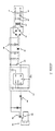
contacts 30 are accessible to the user of the electrical of electronic equipment through output leads 32, and can be used in various ways. The contacts can be wired in series with the power supply to the equipment to be protected, for example, or can be connected to a reset or disable/enable input of the equipment. In the case of the electronic equipment being a burglar alarm, theswitch 30 will operate to reset the alarm or to prevent the alarm from reacting to external stimuli for a time set by thetiming device 24. Alternatively, the output signal of the timer can be applied directly to a reset input of the equipment. For example, this output signal can be detected by hardware or software in computer-based equipment. Thetiming device 24 can be set to deliver an output signal for a time period equivalent to the maximum likely duration of electromagnetic interference caused by a lightning strike, for example. - Figure 3 shows an alternative, second embodiment of the interference prevention circuit. An
antenna 110 is provided in the form of a pick-up wire which senses interference relative to a referencemains earth lead 112. The output of the antenna is connected via adecoupling capacitor 114 and aresistor 116 to a fullwave rectifier bridge 118. The bridge output is connected to an opto-isolator 120. The decoupling function of the circuit is thus performed both by thecapacitor 114 and the opto-isolator 120, which provide galvanic isolating between the circuit and the outside world. The frequency discrimination function of the circuit is performed by the RC high pass filter formed by thecapacitor 114 and theresistor 116, and the high frequency cut-off of the opto-isolator 120. - The output of the opto-
isolator 120 is fed to the base of atransistor 122 via a pair ofresistors resistor 116, are selected to determine the discrimination threshold of the circuit, that is, the magnitude of the input signal which is required in order to turn thetransistor 122 on. - When a sufficiently large input (interference) signal is detected, the
transistor 122 turns on, and provides a negative going pulse to the trigger input of atimer 128. As in the first embodiment, thetimer 128 provides an output signal having a preset duration, which is determined by an RC network. The output of the timer is fed to alight emitting diode 130, which provides a visual indication of the period for which the timer holds its output signal on. Arelay 132 is engergised, via a current limiting resistor 134, by the output of thetimer 128, and operatescontacts 136 which are, again, accessible to the user of the electrical or electronic equipment to be protected via output leads 138. - As mentioned previously, the output signal of the
timer 128 can be applied directly to the protected equipment as a reset signal. This is useful where speed is important, and where galvanic isolation is not required. - The invention is not confined to alarm applications, but may be used to reset or protect any electronic or electrical equipment, such as computer installations, which may be affected by transient electromagnetic interference. The invention may also form part of a whole electrical protection scheme, incorporating additional circuitry. It will be understood that "protect" and "protection" are used in a broad sense in this specification, and it is intended to convey that the invention can provide protection against malfunctioning or error conditions, as well as protection against damage in certain cases.
Claims (20)
detection means (1) for detecting the electromagnetic interference and generating an input signal representative of the interference;
level detection means (5) for comparing the level of the input signal to a predetermined threshold level; and
control means (6, 7) responsive to the level detection means for generating an output signal in the event of the level of the input signal exceeding the predetermined threshold.
Applications Claiming Priority (2)
| Application Number | Priority Date | Filing Date | Title |
|---|---|---|---|
| ZA886541 | 1988-09-02 | ||
| ZA886541 | 1988-09-02 |
Publications (2)
| Publication Number | Publication Date |
|---|---|
| EP0357343A2 true EP0357343A2 (en) | 1990-03-07 |
| EP0357343A3 EP0357343A3 (en) | 1990-12-27 |
Family
ID=25579401
Family Applications (1)
| Application Number | Title | Priority Date | Filing Date |
|---|---|---|---|
| EP19890308612 Withdrawn EP0357343A3 (en) | 1988-09-02 | 1989-08-24 | Method and apparatus for protecting electrical equipment |
Country Status (1)
| Country | Link |
|---|---|
| EP (1) | EP0357343A3 (en) |
Cited By (3)
| Publication number | Priority date | Publication date | Assignee | Title |
|---|---|---|---|---|
| GB2257281A (en) * | 1991-06-07 | 1993-01-06 | Advance Security Inc | An alarm system |
| DE102004029360B4 (en) * | 2004-06-17 | 2007-06-21 | Siemens Ag | Device with an operating state and an interruption state |
| WO2009116849A2 (en) * | 2008-03-17 | 2009-09-24 | Pak Chuen Chang | Electrical interface protecting apparatus |
Citations (6)
| Publication number | Priority date | Publication date | Assignee | Title |
|---|---|---|---|---|
| CH105100A (en) * | 1923-04-26 | 1924-06-02 | Oerlikon Maschf | Process and device for the protection of electrical systems against undesired spark and arcing. |
| GB1030243A (en) * | 1963-02-01 | 1966-05-18 | Napier & Son Ltd | Means for detecting a fault on an electrical supply system |
| GB1119941A (en) * | 1966-08-19 | 1968-07-17 | George Scott Bowman | Protection device |
| DE1279512B (en) * | 1967-06-28 | 1968-10-03 | August Woerl | Circuit to prevent false alarms in monitoring systems with electromagnetic fields or sound or ultrasonic fields |
| US4206451A (en) * | 1975-11-05 | 1980-06-03 | Honeywell Inc. | Intrusion detection system |
| US4466071A (en) * | 1981-09-28 | 1984-08-14 | Texas A&M University System | High impedance fault detection apparatus and method |
-
1989
- 1989-08-24 EP EP19890308612 patent/EP0357343A3/en not_active Withdrawn
Patent Citations (6)
| Publication number | Priority date | Publication date | Assignee | Title |
|---|---|---|---|---|
| CH105100A (en) * | 1923-04-26 | 1924-06-02 | Oerlikon Maschf | Process and device for the protection of electrical systems against undesired spark and arcing. |
| GB1030243A (en) * | 1963-02-01 | 1966-05-18 | Napier & Son Ltd | Means for detecting a fault on an electrical supply system |
| GB1119941A (en) * | 1966-08-19 | 1968-07-17 | George Scott Bowman | Protection device |
| DE1279512B (en) * | 1967-06-28 | 1968-10-03 | August Woerl | Circuit to prevent false alarms in monitoring systems with electromagnetic fields or sound or ultrasonic fields |
| US4206451A (en) * | 1975-11-05 | 1980-06-03 | Honeywell Inc. | Intrusion detection system |
| US4466071A (en) * | 1981-09-28 | 1984-08-14 | Texas A&M University System | High impedance fault detection apparatus and method |
Cited By (4)
| Publication number | Priority date | Publication date | Assignee | Title |
|---|---|---|---|---|
| GB2257281A (en) * | 1991-06-07 | 1993-01-06 | Advance Security Inc | An alarm system |
| DE102004029360B4 (en) * | 2004-06-17 | 2007-06-21 | Siemens Ag | Device with an operating state and an interruption state |
| WO2009116849A2 (en) * | 2008-03-17 | 2009-09-24 | Pak Chuen Chang | Electrical interface protecting apparatus |
| WO2009116849A3 (en) * | 2008-03-17 | 2009-12-23 | Pak Chuen Chang | Electrical interface protecting apparatus |
Also Published As
| Publication number | Publication date |
|---|---|
| EP0357343A3 (en) | 1990-12-27 |
Similar Documents
| Publication | Publication Date | Title |
|---|---|---|
| US5224006A (en) | Electronic circuit breaker with protection against sputtering arc faults and ground faults | |
| US6504692B1 (en) | AFCI device which detects upstream and downstream series and parallel ARC faults | |
| US7099129B2 (en) | Ground fault circuit interrupter incorporating miswiring prevention circuitry | |
| US5291208A (en) | Incipient lightning detection and device protection | |
| US5940256A (en) | Circuit breaker responsive to repeated in-rush currents produced by a sputtering arc fault | |
| CA2207239C (en) | Apparatus for envelope detection of low current arcs | |
| CA2175514C (en) | Intelligent ground fault circuit interrupter | |
| EP1174974B1 (en) | Arc fault detection in ac electric power systems | |
| CA2278379C (en) | Apparatus sensitive to arc amplitude for envelope detection of low current arcs | |
| US5521603A (en) | Incipient lightning detection and device protection | |
| US6556397B2 (en) | Device and method for detecting arc fault | |
| MXPA97005845A (en) | Device of detection of arc failure and circuit circuit that incorporates it | |
| US4053815A (en) | Ground fault interrupters | |
| EP0357343A2 (en) | Method and apparatus for protecting electrical equipment | |
| US8711531B2 (en) | Electrical installation arrangement | |
| KR20040028684A (en) | Detection of arcing in dc electrical systems | |
| GB2268011A (en) | Residual current device | |
| US4243982A (en) | Current monitor | |
| US5225815A (en) | Monitor for a polyphase rectifier which detects open diodes by sensing a signal below a predetermined threshold | |
| US3997890A (en) | Alarm system with supervisory system to detect severing or bridging of detection switches | |
| US4142219A (en) | Two-wire system including signal receiving section and detection section with protected relay | |
| SU942088A1 (en) | Alarm | |
| GB1558473A (en) | Power supplies for alarm systems | |
| JPS62236100A (en) | Abnormality detection system | |
| JPS5856097A (en) | Invasion alarm |
Legal Events
| Date | Code | Title | Description |
|---|---|---|---|
| PUAI | Public reference made under article 153(3) epc to a published international application that has entered the european phase |
Free format text: ORIGINAL CODE: 0009012 |
|
| AK | Designated contracting states |
Kind code of ref document: A2 Designated state(s): AT BE CH DE ES FR GB GR IT LI LU NL SE |
|
| RIN1 | Information on inventor provided before grant (corrected) |
Inventor name: LAGESSE, RENE BRUNO Inventor name: BOURN, GAVIN WILLIAM Inventor name: GELDENHUYS, HENDRIK JACOBUS |
|
| PUAL | Search report despatched |
Free format text: ORIGINAL CODE: 0009013 |
|
| AK | Designated contracting states |
Kind code of ref document: A3 Designated state(s): AT BE CH DE ES FR GB GR IT LI LU NL SE |
|
| STAA | Information on the status of an ep patent application or granted ep patent |
Free format text: STATUS: THE APPLICATION IS DEEMED TO BE WITHDRAWN |
|
| 18D | Application deemed to be withdrawn |
Effective date: 19910628 |