EP0358910B1 - Image recognition system and method - Google Patents
Image recognition system and method Download PDFInfo
- Publication number
- EP0358910B1 EP0358910B1 EP89113971A EP89113971A EP0358910B1 EP 0358910 B1 EP0358910 B1 EP 0358910B1 EP 89113971 A EP89113971 A EP 89113971A EP 89113971 A EP89113971 A EP 89113971A EP 0358910 B1 EP0358910 B1 EP 0358910B1
- Authority
- EP
- European Patent Office
- Prior art keywords
- image
- pattern
- recognition system
- recited
- signature
- Prior art date
- Legal status (The legal status is an assumption and is not a legal conclusion. Google has not performed a legal analysis and makes no representation as to the accuracy of the status listed.)
- Expired - Lifetime
Links
Images


Classifications
-
- H—ELECTRICITY
- H04—ELECTRIC COMMUNICATION TECHNIQUE
- H04N—PICTORIAL COMMUNICATION, e.g. TELEVISION
- H04N17/00—Diagnosis, testing or measuring for television systems or their details
-
- G—PHYSICS
- G06—COMPUTING; CALCULATING OR COUNTING
- G06V—IMAGE OR VIDEO RECOGNITION OR UNDERSTANDING
- G06V40/00—Recognition of biometric, human-related or animal-related patterns in image or video data
- G06V40/10—Human or animal bodies, e.g. vehicle occupants or pedestrians; Body parts, e.g. hands
- G06V40/16—Human faces, e.g. facial parts, sketches or expressions
-
- H—ELECTRICITY
- H04—ELECTRIC COMMUNICATION TECHNIQUE
- H04H—BROADCAST COMMUNICATION
- H04H60/00—Arrangements for broadcast applications with a direct linking to broadcast information or broadcast space-time; Broadcast-related systems
- H04H60/35—Arrangements for identifying or recognising characteristics with a direct linkage to broadcast information or to broadcast space-time, e.g. for identifying broadcast stations or for identifying users
- H04H60/45—Arrangements for identifying or recognising characteristics with a direct linkage to broadcast information or to broadcast space-time, e.g. for identifying broadcast stations or for identifying users for identifying users
-
- H—ELECTRICITY
- H04—ELECTRIC COMMUNICATION TECHNIQUE
- H04N—PICTORIAL COMMUNICATION, e.g. TELEVISION
- H04N21/00—Selective content distribution, e.g. interactive television or video on demand [VOD]
- H04N21/40—Client devices specifically adapted for the reception of or interaction with content, e.g. set-top-box [STB]; Operations thereof
- H04N21/41—Structure of client; Structure of client peripherals
- H04N21/422—Input-only peripherals, i.e. input devices connected to specially adapted client devices, e.g. global positioning system [GPS]
- H04N21/42201—Input-only peripherals, i.e. input devices connected to specially adapted client devices, e.g. global positioning system [GPS] biosensors, e.g. heat sensor for presence detection, EEG sensors or any limb activity sensors worn by the user
Definitions
- the present invention relates generally to image recognition systems, and more particularly to image recognition systems and methods for use with television audience measurement and marketing data collection systems.
- United States Patent No. 3,056,135 describes a methods and apparatus for automatically determining the listening habits of wave signal receiver users.
- the method disclosed in this patent provides a record of the number and types of persons using a wave signal receiver by monitoring the operational conditions of the receiver and utilizing both strategicallly placed switches for counting the number of persons entering, leaving and within a particular area and a photographic recorder for periodically recording the composition of the audience.
- a mailable magazine provides a record of both the audience composition and the receiver operation information for manual processing by a survey organization.
- acquiring data is slow and further many viewing audience members object to being identified from the photographic record.
- United States Patent No. 4,644,509 discloses an ultrasonic, pulse-echo method and apparatus for determining the numbers of persons in the audience and the composition of the audience of a radio receiver and/or a television receiver.
- First and second reflected ultrasonic wave maps of the monitored area are collected, first without people and second with people who may be present in the monitored area.
- the first collected background defining map is substracted from the second collected map to obtain a resulting map.
- the resulting map is processed to identify clusters having a minimum intensity.
- a cluster size of the thus identified clusters is utilized to identify clusters corresponding to people in an audience. While this arrangement is effective for counting viewing audience members, individual audience members cannot be identified.
- a plurality of feature image signatures are stored corresponding to each of the plurality of predetermined patterns.
- a universal feature image signature is stored that includes each of the stored feature image signatures.
- a predefined series of portions of a captured video image is sequentially compared with the universal feature image signature to identify matching portions.
- Each of the identified matching video image portions is compared with the stored feature image signatures to identify the predetermined pattern.
- Each of the plurality of feature image signatures and the universal feature image signature are stored in a distinct memory space of a predetermined capacity.
- the feature image signatures are generated by processing a plurality of video images of the pattern to be identified.
- a signature from each of the processed video images is extracted and stored in the corresponding predetermined memory space for the particular pattern and in the predetermined memory space for the universal feature image signature.
- a feature image signature is stored corresponding to each predetermined individual member's face of a viewing audience.
- An audience scanner includes audience locating circuitry for locating individual audience members in the monitored area.
- a video image is captured and processed for a first one of the located individual audience members.
- a portion of the processed video image is identified that matches a stored universal image signature that includes each of the feature image signatures. The identified portion is compared with the stored feature image signatures to identify the audience member. These steps are repeated to identify all of the located individual audience members in the monitored area.
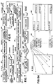
- FIG. 1 there is illustrated a block diagram of a new and improved image recognition system according to the invention generally designated by the reference numeral 10. While the image recognition system 10 is depicted and generally described herein for use with a television receiver to identify individual members of a viewing audience, the principles of the present invention are also applicable to other image recognition systems.
- the image recognition system 10 includes an audience scanner 12 for scanning and capturing an image of the viewing audience members within a monitored area, and a control command processor subsystem 14 for performing control operations and for storing and processing captured images.
- a data transfer device 16 is used for periodically transferring stored data to a central computer (not shown) of the television audience measurement and/or marketing data collection systems.
- the image recognition system 10 includes an audience location subsystem 18 illustrated in FIG. 3 for locating the audience members within the monitored area, a distance measurement subsystem 20 illustrated in FIG. 4 for identifying the distance between audience members and the audience scanner 12, an illumination controller 22 and a scanner controller 24 for providing illumination and motor control signals to the audience scanner 12.
- An audience recognition subsystem 26 for learning and for recognizing feature image signatures of the audience members is illustrated in FIGS. 6 and 7.
- the audience scanner 12 includes a video camera 28 providing a video image signal at a line 28A that is applied to the audience recognition subsystem 26.
- An infrared video camera for example, such as a Model CCD1200 IR Microcam, manufactured and sold by Electrophysics Corporation of Nutley, New Jersey, may be employed for the video camera 28.
- An infrared sensor 30 provides a sensed infrared signal at a line 30A that is applied to the audience location subsystem 18.
- a parallel opposed dual pyroelectric infrared detector used in conjunction with an optic focusing device including a pair of fixed surface mirrors and a Fresnel lens, may be used for the infrared sensor 30, for example, such as an Eltec Model 4192 and an Eltec Model 826C manufactured and sold by Eltec Instruments, Inc. of Daytona Beach, Florida.
- An ultrasound transducer 32 such as a 50 KHz electrostatic transducer, for transmitting and for receiving ultrasonic signals provides a distance pulse echo signal at a line 32A that is applied to the distance measurement subsystem 20.
- a pair of infrared illumination devices 34 for illuminating the monitored area are operatively controlled by the illumination controller 22.
- a scanner drive 36, such as a stepping motor is operatively controlled by the scanner controller 24 for stepwise angular rotation of the video camera 28 for scanning the monitored area.
- FIG. 3 provides a block diagram of an audience location subsystem 18 of the image recognition system 10.
- the sensed voltage signal output of the infrared sensor 30 at line 30A corresponds to the temperature distribution of the monitored area.
- the sensed infrared signal at line 30A is applied to a preamplifier device 38.
- the amplified infrared signal is applied to a low pass filter 40 for providing a filtered infrared signal that is applied to an analog-to-digital A/D converter 42 which generates a digital representation of the processed infrared signal.
- the digitized signal is applied to an audience location computation logic circuit 44 to identify directions within the monitored area corresponding to the possible locations of individual audience members.
- the identified directions signal at line 46 is applied to the control command processor subsystem 14.
- the separate audience location computation logic circuit 44 may be eliminated with the digitized signal output of the A/D converter 42 applied to the control command processor subsystem 14. Then the direction identifying function of the computation logic circuit 44 is performed by the control command processor subsystem 14.
- the control command processor subsystem 14 utilizes are identified directions signal at line 46 from the audience location subsystem 18 to initiate operation of the distance measurement subsystem 20.
- FIG. 4 provides a block diagram of a distance measurement subsystem 20 of the image recognition system 10.
- An ultrasound range module 48 drives the ultrasound transducer 32 for transmitting an ultrasonic burst signal and for receiving an echo signal responsive to an enable or initiate input signal applied by a transmitter controller device 50.
- An output echo signal of the ultrasound range module 48 is coupled to the control command processor subsystem 14 via a distance measurement logic circuit 52 which converts the echo signal to a suitable format for use by the control command processor subsystem 14.
- a sonar ranging module for example, such as an integrated circuit device type SN28827 manufactured and sold by Texas Instruments may be used for the ultrasound range module 48.
- Bidirectional communication with the control command processor subsystem 14 at a line 54 include the processed echo signal output of the distance measurement logic circuit 52 and an input control signal to the transmitter controller 50.
- the processed echo signal representative of distance between the scanner 12 and the located individual audience member is utilized by the control command processor subsystem 14 for adjusting the focus and zooming functions of the video camera 28.
- FIG. 5 provides a block diagram representation of the control command processor subsystem 14 of the image recognition system 10.
- the control command processor subsystem 14 includes a central processing unit 56, such as, an Intel 80286 high performance 16-bit microprocessor with integrated memory management and adapted for multi-tasking systems and an associated memory device 58.
- the central processing unit 56 is programmable to perform the control and signal processing functions and includes, in known manner, asynchronous input signal timing and clock control bus timing functions.
- An interface device 60 is provided in conjunction with the central processing unit 56 to enable bidirectional communications between the image recognition system 10 and a host system for a particular application.
- the host system may be a home unit (not shown) of the type as described in United States patent 4,697,209 to David A. Kiewit and Daozheng Lu and/or the data transfer device 16.
- the control command processor subsystem 14 further may include an image display 62, a computer display 64 and a keyboard 66 for use during the installation of the image recognition system 10.
- Control signals from the central processing unit 56 at a line 68 are applied to the illumination controller 22 for controlling illumination of the monitored area.
- Motor control signals at a line 70 from the central processing unit 56 are applied to the scanner controller 24 which are translated and applied to the stepping motor 36 at a line 36A.
- Feedback position signals may be provided to the central processing unit 56.
- Bidirectional communications are provided between the central processing unit 56 and the audience recognition subsystem 26 illustrated at a line 72.
- FIGS. 6 and 7 provide a block diagram representation of the audience recognition subsystem 26.
- a learning operational mode of the audience recognition subsystem 26 is illustrated.
- the infrared image output signal at line 28A of the infrared video camera 28 is applied to an image acquisition block 74 coupled to an analog-to-digital A/D converter 76 which generates a digital representation of the infrared image signal.
- a face imager registration block 78 identifies a predetermined portion (mxn) pixels of the digitized image signal.
- a gray-level subimage output of the face image registration block 78 at a line G-Sub is applied to a normalization block 80.
- the normalized output of block 80 is applied to a thresholding block 82 to provide a thresholded, binary level face image output at a line B-Sub.
- Each pixel of the (mxn) threshold, binary level face or B-Sub image is represented by a single binary digit or bit, or 2500 bits for the 50x50 pixels.
- the B-Sub image signal is applied to a feature signature extraction block 84.
- An extracted pattern image signature output of the feature signature extraction block 84 is stored in both an individual face storage library (IFL) 86 and a universal face model (UFM) storage block 88.
- the universal face model UFM includes all the individual pattern image or face signatures stored within the individual face library IFL.
- a stop function flag is set at stop blocks 90 for updating the image libraries performed by the control command processor subsystem 14 as illustrated in FIG. 8A.
- FIG 6A provides a graphical representation of a B-sub image including mxn pixels. Each of the mxn pixels is either a zero or a one.
- the B-sub image pixel data is utilized to extract the pattern image signature for storing in the learning operational mode (FIG. 6) and to extract the pattern image signature for comparing with the universal image signature and the pattern image signatures in the recognition operational mode illustrated in FIG. 7.
- a pseudo random predetermined sequence of the mxn B-Sub image bits defines a predetermined number T of feature positions used for storing the extracted feature signature output of the feature signature extraction block 84.
- Each feature position has a predetermined length L, where the value of L is between 3 and 10.
- T a total memory space for each of the pattern or face image signature and the universal pattern image signature equal T multiplied by b or, for example, 357 positions x 16 bytes/position or 5712 bytes.
- the corresponding memory space is represented by the reference character 86 corresponding to the IFL block 86.
- the logic steps performed for storing the individual face and the universal face model are described with respect to FIG. 8B.
- a distinct memory space of a predetermined capacity is defined for the universal pattern image signature and each of the pattern image or individual face signatures within the image face library.
- individual face signatures TxP
- bxTxP IFL defined memory spaces
- bxT UFM defined memory space
- Multiple face images are learned for each of the audience members P by sequentially processing a series of video images of the video camera 28 by the image signal processing blocks of FIG. 6 for each of the audience members. All of the resulting extracted pattern image signatures for each of the audience members are stored in the particular corresponding memory space of the IFL memory spaces.
- FIG. 7 provides a block diagram representation of the recognition mode of the audience recognition subsystem 26.
- the digital representation of the infrared image signal from the analog-to-digital A/D converter 76 corresponding to an identified direction of an audience member by the audience location subsystem 18 is applied to a zooming and vertical strip image block 92.
- a first search area matrix (mxn)i is identified by a search area registration block 94.
- a gray-level subimage output G-Sub of the search area regis-tration block 94 is applied to a normalization block 96.
- the normalized output of block 96 is applied to a thresholding block 98 to provide a thresholded, binary level search area image output B-Sub.
- the search area B-Sub image is compared with the universal pattern image signature at a block 100 labelled recognition for UFM.
- the search area B-Sub image matches or exceeds a predetermined correlation threshold with the universal pattern image signature
- B-Sub image After each of the search area matrices have been processed, more than one B-Sub image may be found that match the universal face model and an individual face library.
- the search area B-Sub image having the best matching rate or highest correlation with an individual face in the individual face library is identified at a conclusion block 108.
- the logic steps performed for recognizing the universal face model and the individual face are described with respect to FIG. 8B.
- An output signal at a line 110 is then stored corresponding to the particular identified individual member of the viewing audience.
- the thus identified individual viewing member data can be stored together with other parameter data of a television data collection system, such as channel reception of a monitored receiver.
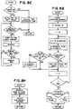
- FIG. 8A there is a main flow chart illustrating the logical steps performed by the control command processor subsystem 14 of the image recognition system 10.
- the sequential steps begin with an initialization routine. Then if a stop function is set, the pattern image signatures and universal pattern image signature memory spaces can be updated to include the IFL and UFM signatures stored at blocks 86 and 88 of FIG. 6. Otherwise, it is determined whether any function or mode has been selected, such as by a remote control or keyboard entry. If yes, then the selected function or mode is set or updated and then performed. Otherwise, the next sequential function or mode of modes 1-7 is performed.
- FIG. 8B is a flow chart illustrating the logic steps performed for learning and recognizing the universal face model and the individual face.
- the sequential operations begin by setting a memory space address ADDR to the starting address with N-found set to zero.
- the corresponding bit position B bit of ADDR + A byte is determined by the particular feature value S, where S is between 0 and 127, A equals an integer value S/8 and B equals S mod 8 or the residue of S after A bytes.
- An individual audience member face image may be learned multiple times (R) with R possible different extracted signatures resulting, depending on any changed facial expressions or various profiles of the audience member.
- R Each of the extracted feature signatures is sequentially stored within the corresponding pattern image signature memory space for the particular audience member by repeating the sequential signal processing of FIG. 6 and the learning or storing steps of FIG. 8B.
- the sequential steps for the recognition mode are performed, such as at the recognition for UFM block 100 when the search area B-Sub image is compared with the universal pattern image signature or at the block 104 when the search area B-Sub image is compared with individual pattern image signatures.
- the resulting N-found value is compared with a threshold value. If resulting N-found value is less than the threshold value, then a FALSE or no recognition for the UFM or the particular IFL is indicated. If resulting N-found value is greater than or equal to the threshold value, then a TRUE or a recognition of the UFM or the particular IFL is indicated.
- FIG. 8C is a flow chart illustrating an operational function or mode 1 logical steps performed to add to the individual pattern image signatures and universal pattern image signature memory space or library. The sequential steps begin with a get and display a picture subroutine illustrated in FIG. 8D. Next a search all libraries subroutine illustrated in FIG. 8E is performed. The results are displayed and added to the library.
- the get and display a picture subroutine of FIG. 8D starts with an image acquisition step (block 74 of FIG. 6).
- the infrared video image is processed (blocks 76, 78, 80 and 82 of FIG. 6) to provide a binary picture (B-sub image).
- a ratio of the ones in the resulting binary picture is calculated and the resulting binary picture is displayed.
- the search all libraries subroutine begins with a check of the exposure time based on the calculated ratio of ones and if adjustment is required, then the sequential operation return without searching the libraries. Otherwise, if adjustment of the exposure time is not required, then an initial MAX value is set for the predetermined N-found value.
- a first library is searched (block 104 of FIG. 7 and FIG. 8B) and if the result N-found value is greater than the initial MAX value, then the MAX value is updated. Otherwise the MAX value is not changed. Then a next library is searched and the result is compared to the resulting MAX value and adjusted, until all the libraries have been searched.
- FIG. 8F is a flow chart illustrating an operational function or mode 2 logical steps performed to verify and add to library. The sequential steps begin with the get and display the picture subroutine illustrated in FIG. 8D. Next the search all libraries subroutine illustrated in FIG. 8E is performed. The results are displayed and added to the identified correct library.
- FIG. 8G is a flow chart illustrating an operational function or mode 3 logical steps performed to search and display. The sequential steps begin with a get and display the picture subroutine illustrated in FIG. 8D. Next the search all libraries subroutine illustrated in FIG. 8E is performed. The results are displayed.
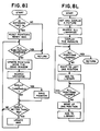
- FIG. 8H is a flow chart illustrating an operational function or mode 4 logical steps performed to locate head and search. The sequential steps begin with a search raw picture for heads subroutine illustrated in FIG. 8I. Next a locate and search head(s) subroutine illustrated in FIG. 8J is performed.
- the search raw picture for head(s) subroutine begins with a check of the exposure time and if adjustment is required, then the sequential operation return without performing any searching for heads. Otherwise, if adjustment of the exposure time is not required, then an initial MAX value is set for the predetermined N-found value and a search area pointer i is reset.
- the first search area matrix is identified and compared with the universal pattern image signature UFM (block 100 of FIG. 7). The result is compared with the set for the correlation threshold MAX value, and if the result is greater than the initial MAX value, then that search area pointer is saved and the MAX value is updated. Otherwise, the search area pointer is not saved and the MAX value is not changed. Then the search area pointer value is updated and the next search area matrix is identified and the sequential steps are repeated until the total raw picture has been searched.
- FIG. 8J illustrates the locate and search head(s) subroutine performed by the control command processor subsystem 14 in the mode 4. If one search area pointer is stored in the subroutine of FIG. 8I, then the search area window is set to the identified search area matrix by the saved pointer value which corresponds to the head image portion. The exposure time is adjusted and the search all libraries subroutine of FIG. 8E is performed and the results are displayed.
- the MAX value is reset for a predetermined initial value. Then the search area window is set to the first identified search area matrix by the first saved pointer value which corresponds to a first head image portion. A local normalization is performed on the search area matrix data and the search all libraries subroutine of FIG. 8E is performed, and if the result is greater thanthe initial MAX value, then the MAX value is updated. Otherwise the MAX value is not changed. Then a next search area window is set to the next saved pointer value which corresponds to a next head image portion and the sequential steps are repeated until all the head image portions have been searched. Then the search area window is set to the identified search area matrix having the highest MAX value which corresponds to the head image portion. A local normalization is performed on the search area matrix data and the search all libraries subroutine of FIG. 8E is performed and the results are displayed.
- FIG. 8K is a flow chart illustrating an operational function or mode 5 logical steps performed to scan and search the monitored area. The sequential steps begin with scanning of the monitored area. Then the video camera 28 is pointed to audience members within the monitored area and the mode 4 operations of FIG. 8H are performed.
- FIG. 8L is a flow chart illustrating an operational function or mode 6 logical steps performed to shift and learn.
- the sequential steps begin with the get and display the picture subroutine illustrated in FIG. 8D.
- the search all libraries subroutine illustrated in FIG. 8E is performed.
- the results are displayed and if all positions have been learned, then the sequential operation return without adding to the library. Otherwise, the audience member image is shifted to the left one position and added to the pattern image signature IFL and universal pattern image signature UFM. Then the audience member image is moved up one position and sequentially repeated until all positions have been learned and added to the library.
- FIG. 8M is a flow chart illustrating an operational function or mode 7 logical steps performed to search and pause.
- the sequential steps begin with the search raw picture for heads subroutine illustrated in FIG. 8I. Net the locate and search head(s) subroutine illustrated in FIG. 8J is performed. Then if a continue decision is yes, the sequential mode 7 steps are repeated.
Abstract
Description
- The present invention relates generally to image recognition systems, and more particularly to image recognition systems and methods for use with television audience measurement and marketing data collection systems.
- Manual systems for determining the viewing/listening habits of the public are prone to inaccuracies resulting from the entry of erroneous data that may be intentionally or unintentionally entered, and are slow in acquiring data.
- United States Patent No. 3,056,135 describes a methods and apparatus for automatically determining the listening habits of wave signal receiver users. The method disclosed in this patent provides a record of the number and types of persons using a wave signal receiver by monitoring the operational conditions of the receiver and utilizing both strategicallly placed switches for counting the number of persons entering, leaving and within a particular area and a photographic recorder for periodically recording the composition of the audience. A mailable magazine provides a record of both the audience composition and the receiver operation information for manual processing by a survey organization. Thus a disadvantage is that acquiring data is slow and further many viewing audience members object to being identified from the photographic record.
- United States Patent No. 4,644,509 discloses an ultrasonic, pulse-echo method and apparatus for determining the numbers of persons in the audience and the composition of the audience of a radio receiver and/or a television receiver. First and second reflected ultrasonic wave maps of the monitored area are collected, first without people and second with people who may be present in the monitored area. The first collected background defining map is substracted from the second collected map to obtain a resulting map. The resulting map is processed to identify clusters having a minimum intensity. A cluster size of the thus identified clusters is utilized to identify clusters corresponding to people in an audience. While this arrangement is effective for counting viewing audience members, individual audience members cannot be identified.
- Various image recognition arrangements and systems are known for recognizing patterns within a captured video image. However, the conventional pattern recognition systems are impractical and uneconomical for identifying individual audience members of a viewing audience due to the vast information storage and computing requirements that would be needed in the conventional systems. It is desirable to provide an image recognition system having the capability to identify individual members of the viewing audience.
- It is therefore the main object of the present invention to provide an improved recognition system and method for identifying a pattern of a plurality of predetermined patterns in a video image and, particularly, for identifying predetermined individual members of a viewing audience in a monitored area.
- This object is achieved by the image recognition system and method as defined in the appended claims.
- In accordance with a preferred embodiment of the invention a plurality of feature image signatures are stored corresponding to each of the plurality of predetermined patterns. A universal feature image signature is stored that includes each of the stored feature image signatures. A predefined series of portions of a captured video image is sequentially compared with the universal feature image signature to identify matching portions. Each of the identified matching video image portions is compared with the stored feature image signatures to identify the predetermined pattern.
- Each of the plurality of feature image signatures and the universal feature image signature are stored in a distinct memory space of a predetermined capacity. The feature image signatures are generated by processing a plurality of video images of the pattern to be identified. A signature from each of the processed video images is extracted and stored in the corresponding predetermined memory space for the particular pattern and in the predetermined memory space for the universal feature image signature.
- A feature image signature is stored corresponding to each predetermined individual member's face of a viewing audience. An audience scanner includes audience locating circuitry for locating individual audience members in the monitored area. A video image is captured and processed for a first one of the located individual audience members. A portion of the processed video image is identified that matches a stored universal image signature that includes each of the feature image signatures. The identified portion is compared with the stored feature image signatures to identify the audience member. These steps are repeated to identify all of the located individual audience members in the monitored area.
- In the following the invention in a preferred form in explained in connection with the accompanying drawings in which:
- FIG. 1 is a block diagram of an image recognition system according to the present invention;
- FIG. 2 is a perspective view partly broken away to show interior details of an audience scanner of the image recognition system of FIG. 1;
- FIG. 3 is a block diagram of an audience location subsystem of the image recognition system of FIG. 1;
- FIG. 4 is a block diagram of a distance measurement subsystem of the image recognition system of FIG. 1;
- FIG. 5 is a block diagram of a control command processor subsystem of the image recognition system of FIG. 1;
- FIG. 6 is a block diagram of a learning functional portion of an audience recognition subsystem of the image recognition system of FIG. 1;
- FIG. 6A is a graphical representation of a binary subimage and feature identifying logic for extracting and storing an image signature of the image recognition system of FIG. 1;
- FIG. 7 is a block diagram of a recognition functional portion of the audience recognition subsystem of the image recognition system of FIG. 1;
- FIGS. 8A - 8M are flow charts illustrating the logical steps performed by the image recognition system of FIG. 1.
- Referring now to the drawings, with particular attention to FIG. 1, there is illustrated a block diagram of a new and improved image recognition system according to the invention generally designated by the
reference numeral 10. While theimage recognition system 10 is depicted and generally described herein for use with a television receiver to identify individual members of a viewing audience, the principles of the present invention are also applicable to other image recognition systems. - As its major components, the
image recognition system 10 includes anaudience scanner 12 for scanning and capturing an image of the viewing audience members within a monitored area, and a controlcommand processor subsystem 14 for performing control operations and for storing and processing captured images. Adata transfer device 16 is used for periodically transferring stored data to a central computer (not shown) of the television audience measurement and/or marketing data collection systems. Theimage recognition system 10 includes anaudience location subsystem 18 illustrated in FIG. 3 for locating the audience members within the monitored area, adistance measurement subsystem 20 illustrated in FIG. 4 for identifying the distance between audience members and theaudience scanner 12, anillumination controller 22 and ascanner controller 24 for providing illumination and motor control signals to theaudience scanner 12. Anaudience recognition subsystem 26 for learning and for recognizing feature image signatures of the audience members is illustrated in FIGS. 6 and 7. - Referring also to FIG. 2, the
audience scanner 12 includes avideo camera 28 providing a video image signal at aline 28A that is applied to theaudience recognition subsystem 26. An infrared video camera, for example, such as a Model CCD1200 IR Microcam, manufactured and sold by Electrophysics Corporation of Nutley, New Jersey, may be employed for thevideo camera 28. Aninfrared sensor 30 provides a sensed infrared signal at aline 30A that is applied to theaudience location subsystem 18. A parallel opposed dual pyroelectric infrared detector used in conjunction with an optic focusing device including a pair of fixed surface mirrors and a Fresnel lens, may be used for theinfrared sensor 30, for example, such as an Eltec Model 4192 and an Eltec Model 826C manufactured and sold by Eltec Instruments, Inc. of Daytona Beach, Florida. Anultrasound transducer 32, such as a 50 KHz electrostatic transducer, for transmitting and for receiving ultrasonic signals provides a distance pulse echo signal at aline 32A that is applied to thedistance measurement subsystem 20. - A pair of
infrared illumination devices 34 for illuminating the monitored area are operatively controlled by theillumination controller 22. A Model IRL200 infrared room illuminator manufactured and sold by Electrophysics Corporation of Nutley, New Jersey, may be employed for theillumination devices 34, although various illumination devices such as infrared lasers, light emitting diodes or a filtered flash lamp can be used. Ascanner drive 36, such as a stepping motor is operatively controlled by thescanner controller 24 for stepwise angular rotation of thevideo camera 28 for scanning the monitored area. - FIG. 3 provides a block diagram of an
audience location subsystem 18 of theimage recognition system 10. The sensed voltage signal output of theinfrared sensor 30 atline 30A corresponds to the temperature distribution of the monitored area. The sensed infrared signal atline 30A is applied to apreamplifier device 38. The amplified infrared signal is applied to alow pass filter 40 for providing a filtered infrared signal that is applied to an analog-to-digital A/D converter 42 which generates a digital representation of the processed infrared signal. The digitized signal is applied to an audience location computation logic circuit 44 to identify directions within the monitored area corresponding to the possible locations of individual audience members. The identified directions signal atline 46 is applied to the controlcommand processor subsystem 14. - Alternatively, the separate audience location computation logic circuit 44 may be eliminated with the digitized signal output of the A/
D converter 42 applied to the controlcommand processor subsystem 14. Then the direction identifying function of the computation logic circuit 44 is performed by the controlcommand processor subsystem 14. - The control
command processor subsystem 14 utilizes are identified directions signal atline 46 from theaudience location subsystem 18 to initiate operation of thedistance measurement subsystem 20. - FIG. 4 provides a block diagram of a
distance measurement subsystem 20 of theimage recognition system 10. Anultrasound range module 48 drives theultrasound transducer 32 for transmitting an ultrasonic burst signal and for receiving an echo signal responsive to an enable or initiate input signal applied by atransmitter controller device 50. An output echo signal of theultrasound range module 48 is coupled to the controlcommand processor subsystem 14 via a distancemeasurement logic circuit 52 which converts the echo signal to a suitable format for use by the controlcommand processor subsystem 14. A sonar ranging module, for example, such as an integrated circuit device type SN28827 manufactured and sold by Texas Instruments may be used for theultrasound range module 48. Bidirectional communication with the controlcommand processor subsystem 14 at aline 54 include the processed echo signal output of the distancemeasurement logic circuit 52 and an input control signal to thetransmitter controller 50. - The processed echo signal representative of distance between the
scanner 12 and the located individual audience member is utilized by the controlcommand processor subsystem 14 for adjusting the focus and zooming functions of thevideo camera 28. - FIG. 5 provides a block diagram representation of the control
command processor subsystem 14 of theimage recognition system 10. The controlcommand processor subsystem 14 includes acentral processing unit 56, such as, anIntel 80286 high performance 16-bit microprocessor with integrated memory management and adapted for multi-tasking systems and an associatedmemory device 58. Thecentral processing unit 56 is programmable to perform the control and signal processing functions and includes, in known manner, asynchronous input signal timing and clock control bus timing functions. Aninterface device 60 is provided in conjunction with thecentral processing unit 56 to enable bidirectional communications between theimage recognition system 10 and a host system for a particular application. The host system may be a home unit (not shown) of the type as described in United States patent 4,697,209 to David A. Kiewit and Daozheng Lu and/or thedata transfer device 16. - The control
command processor subsystem 14 further may include animage display 62, acomputer display 64 and a keyboard 66 for use during the installation of theimage recognition system 10. - Control signals from the
central processing unit 56 at aline 68 are applied to theillumination controller 22 for controlling illumination of the monitored area. Motor control signals at aline 70 from thecentral processing unit 56 are applied to thescanner controller 24 which are translated and applied to the steppingmotor 36 at aline 36A. Feedback position signals may be provided to thecentral processing unit 56. Bidirectional communications are provided between thecentral processing unit 56 and theaudience recognition subsystem 26 illustrated at aline 72. - FIGS. 6 and 7 provide a block diagram representation of the
audience recognition subsystem 26. Referring initially to FIG. 6, a learning operational mode of theaudience recognition subsystem 26 is illustrated. The infrared image output signal atline 28A of theinfrared video camera 28 is applied to animage acquisition block 74 coupled to an analog-to-digital A/D converter 76 which generates a digital representation of the infrared image signal. A faceimager registration block 78 identifies a predetermined portion (mxn) pixels of the digitized image signal. The values of m and n are between 32 and 256, for example, such as a middle pixel image portion including m=50 and n=50. A gray-level subimage output of the faceimage registration block 78 at a line G-Sub is applied to anormalization block 80. The normalized output ofblock 80 is applied to athresholding block 82 to provide a thresholded, binary level face image output at a line B-Sub. Each pixel of the (mxn) threshold, binary level face or B-Sub image is represented by a single binary digit or bit, or 2500 bits for the 50x50 pixels. The B-Sub image signal is applied to a featuresignature extraction block 84. An extracted pattern image signature output of the featuresignature extraction block 84 is stored in both an individual face storage library (IFL) 86 and a universal face model (UFM)storage block 88. The universal face model UFM includes all the individual pattern image or face signatures stored within the individual face library IFL. A stop function flag is set at stop blocks 90 for updating the image libraries performed by the controlcommand processor subsystem 14 as illustrated in FIG. 8A. - FIG 6A provides a graphical representation of a B-sub image including mxn pixels. Each of the mxn pixels is either a zero or a one. The B-sub image pixel data is utilized to extract the pattern image signature for storing in the learning operational mode (FIG. 6) and to extract the pattern image signature for comparing with the universal image signature and the pattern image signatures in the recognition operational mode illustrated in FIG. 7.
- A pseudo random predetermined sequence of the mxn B-Sub image bits defines a predetermined number T of feature positions used for storing the extracted feature signature output of the feature
signature extraction block 84. Each feature position has a predetermined length L, where the value of L is between 3 and 10. Considering a predetermined feature position of length L=7 and with the above example B-Sub image of 2500 bits, a pseudo random sequence of 2500/7 or 357 feature positions results or T=357. Each feature has a value between 0 and (2L-1) or, for example, between 0 and 127 when L=7. Amemory space 2L bits arranged as bytes b, where b equals 2L/8, is used for storing the possible feature values for each of the feature positions or, for example, 2*7 or 128 bits or 16 bytes. Thus a total memory space for each of the pattern or face image signature and the universal pattern image signature equal T multiplied by b or, for example, 357 positions x 16 bytes/position or 5712 bytes. - FIG. 6A illustrates a plurality of feature positions i=0 through i=(T-1) generally designated by the
reference character 84 corresponding to thefeature extraction block 84. The corresponding memory space is represented by thereference character 86 corresponding to theIFL block 86. The first or i=0 feature position value is stored in a corresponding bit position B in a corresponding byte between 0 and (b-1) within thememory space 84. The logic steps performed for storing the individual face and the universal face model are described with respect to FIG. 8B. - A distinct memory space of a predetermined capacity is defined for the universal pattern image signature and each of the pattern image or individual face signatures within the image face library. For example, for a viewing audience including a defined number of audience members P, individual face signatures (TxP) are stored in both the corresponding IFL defined memory spaces (bxTxP) and the UFM defined memory space (bxT). Multiple face images are learned for each of the audience members P by sequentially processing a series of video images of the
video camera 28 by the image signal processing blocks of FIG. 6 for each of the audience members. All of the resulting extracted pattern image signatures for each of the audience members are stored in the particular corresponding memory space of the IFL memory spaces. - FIG. 7 provides a block diagram representation of the recognition mode of the
audience recognition subsystem 26. The digital representation of the infrared image signal from the analog-to-digital A/D converter 76 corresponding to an identified direction of an audience member by theaudience location subsystem 18 is applied to a zooming and verticalstrip image block 92. A first search area matrix (mxn)i is identified by a searcharea registration block 94. A gray-level subimage output G-Sub of the search area regis-tration block 94 is applied to anormalization block 96. The normalized output ofblock 96 is applied to athresholding block 98 to provide a thresholded, binary level search area image output B-Sub. The search area B-Sub image is compared with the universal pattern image signature at ablock 100 labelled recognition for UFM. - If the decision at a
block 102 is that the search area B-Sub image matches or exceeds a predetermined correlation threshold with the universal pattern image signature, then the search area B-Sub image is compared to identify a match with each of the pattern image signatures stored in the individual face library as illustrated at ablock 104. Then or after a decision atblock 102 that the search area B-Sub image does not match the universal pattern image signature, i is incremented by 1 or where i=i+1, at ablock 106 so that a next search matrix (mxn)i is identified by the searcharea registration block 94 and processed as described for the first search area matrix. - After each of the search area matrices have been processed, more than one B-Sub image may be found that match the universal face model and an individual face library. The search area B-Sub image having the best matching rate or highest correlation with an individual face in the individual face library is identified at a
conclusion block 108. The logic steps performed for recognizing the universal face model and the individual face are described with respect to FIG. 8B. An output signal at a line 110 is then stored corresponding to the particular identified individual member of the viewing audience. The thus identified individual viewing member data can be stored together with other parameter data of a television data collection system, such as channel reception of a monitored receiver. - Referring to FIG. 8A, there is a main flow chart illustrating the logical steps performed by the control
command processor subsystem 14 of theimage recognition system 10. The sequential steps begin with an initialization routine. Then if a stop function is set, the pattern image signatures and universal pattern image signature memory spaces can be updated to include the IFL and UFM signatures stored atblocks - FIG. 8B is a flow chart illustrating the logic steps performed for learning and recognizing the universal face model and the individual face. The sequential operations begin by setting a memory space address ADDR to the starting address with N-found set to zero. In the learning mode, an identified feature value from the B-Sub image is set to a corresponding bit position, starting with feature position i=0 and repeated for each feature position to i=356. The corresponding bit position B bit of ADDR + A byte, is determined by the particular feature value S, where S is between 0 and 127, A equals an integer value S/8 and B equals
S mod 8 or the residue of S after A bytes. For example, a feature value S-114 from the B-Sub image for the feature position i=0 is set to the 2nd bit of ADDR + 14 byte. - An individual audience member face image may be learned multiple times (R) with R possible different extracted signatures resulting, depending on any changed facial expressions or various profiles of the audience member. Each of the extracted feature signatures is sequentially stored within the corresponding pattern image signature memory space for the particular audience member by repeating the sequential signal processing of FIG. 6 and the learning or storing steps of FIG. 8B.
- Otherwise if not in the learning mode, then the sequential steps for the recognition mode are performed, such as at the recognition for UFM block 100 when the search area B-Sub image is compared with the universal pattern image signature or at the
block 104 when the search area B-Sub image is compared with individual pattern image signatures. - In the recognition mode, the identified feature value from the B-Sub image is compared to a corresponding bit position, starting with feature position i=0 and repeated for each feature position to i=356. If the corresponding bit position is set, a match is indicated and the N-found value is incremented by one. Otherwise, if the corresponding bit position is not set, nonmatching is indicated and the N-found value is not changed. The next incremental feature position is then compared to the corresponding bit position for the identified feature value.
- After the last feature position i=356 has been identified and compared to identify a match, then the resulting N-found value is compared with a threshold value. If resulting N-found value is less than the threshold value, then a FALSE or no recognition for the UFM or the particular IFL is indicated. If resulting N-found value is greater than or equal to the threshold value, then a TRUE or a recognition of the UFM or the particular IFL is indicated.
- FIG. 8C is a flow chart illustrating an operational function or
mode 1 logical steps performed to add to the individual pattern image signatures and universal pattern image signature memory space or library. The sequential steps begin with a get and display a picture subroutine illustrated in FIG. 8D. Next a search all libraries subroutine illustrated in FIG. 8E is performed. The results are displayed and added to the library. - The get and display a picture subroutine of FIG. 8D starts with an image acquisition step (block 74 of FIG. 6). The infrared video image is processed (blocks 76, 78, 80 and 82 of FIG. 6) to provide a binary picture (B-sub image). A ratio of the ones in the resulting binary picture is calculated and the resulting binary picture is displayed.
- In FIG. 8E, the search all libraries subroutine begins with a check of the exposure time based on the calculated ratio of ones and if adjustment is required, then the sequential operation return without searching the libraries. Otherwise, if adjustment of the exposure time is not required, then an initial MAX value is set for the predetermined N-found value. A first library is searched (block 104 of FIG. 7 and FIG. 8B) and if the result N-found value is greater than the initial MAX value, then the MAX value is updated. Otherwise the MAX value is not changed. Then a next library is searched and the result is compared to the resulting MAX value and adjusted, until all the libraries have been searched.
- FIG. 8F is a flow chart illustrating an operational function or
mode 2 logical steps performed to verify and add to library. The sequential steps begin with the get and display the picture subroutine illustrated in FIG. 8D. Next the search all libraries subroutine illustrated in FIG. 8E is performed. The results are displayed and added to the identified correct library. - FIG. 8G is a flow chart illustrating an operational function or
mode 3 logical steps performed to search and display. The sequential steps begin with a get and display the picture subroutine illustrated in FIG. 8D. Next the search all libraries subroutine illustrated in FIG. 8E is performed. The results are displayed. - FIG. 8H is a flow chart illustrating an operational function or
mode 4 logical steps performed to locate head and search. The sequential steps begin with a search raw picture for heads subroutine illustrated in FIG. 8I. Next a locate and search head(s) subroutine illustrated in FIG. 8J is performed. - In FIG. 8I, the search raw picture for head(s) subroutine begins with a check of the exposure time and if adjustment is required, then the sequential operation return without performing any searching for heads. Otherwise, if adjustment of the exposure time is not required, then an initial MAX value is set for the predetermined N-found value and a search area pointer i is reset. The first search area matrix is identified and compared with the universal pattern image signature UFM (block 100 of FIG. 7). The result is compared with the set for the correlation threshold MAX value, and if the result is greater than the initial MAX value, then that search area pointer is saved and the MAX value is updated. Otherwise, the search area pointer is not saved and the MAX value is not changed. Then the search area pointer value is updated and the next search area matrix is identified and the sequential steps are repeated until the total raw picture has been searched.
- FIG. 8J illustrates the locate and search head(s) subroutine performed by the control
command processor subsystem 14 in themode 4. If one search area pointer is stored in the subroutine of FIG. 8I, then the search area window is set to the identified search area matrix by the saved pointer value which corresponds to the head image portion. The exposure time is adjusted and the search all libraries subroutine of FIG. 8E is performed and the results are displayed. - Otherwise, if more than one pointer value are stored in the subroutine of FIG. 8I, then the MAX value is reset for a predetermined initial value. Then the search area window is set to the first identified search area matrix by the first saved pointer value which corresponds to a first head image portion. A local normalization is performed on the search area matrix data and the search all libraries subroutine of FIG. 8E is performed, and if the result is greater thanthe initial MAX value, then the MAX value is updated. Otherwise the MAX value is not changed. Then a next search area window is set to the next saved pointer value which corresponds to a next head image portion and the sequential steps are repeated until all the head image portions have been searched. Then the search area window is set to the identified search area matrix having the highest MAX value which corresponds to the head image portion. A local normalization is performed on the search area matrix data and the search all libraries subroutine of FIG. 8E is performed and the results are displayed.
- FIG. 8K is a flow chart illustrating an operational function or
mode 5 logical steps performed to scan and search the monitored area. The sequential steps begin with scanning of the monitored area. Then thevideo camera 28 is pointed to audience members within the monitored area and themode 4 operations of FIG. 8H are performed. - FIG. 8L is a flow chart illustrating an operational function or
mode 6 logical steps performed to shift and learn. The sequential steps begin with the get and display the picture subroutine illustrated in FIG. 8D. Next the search all libraries subroutine illustrated in FIG. 8E is performed. The results are displayed and if all positions have been learned, then the sequential operation return without adding to the library. Otherwise, the audience member image is shifted to the left one position and added to the pattern image signature IFL and universal pattern image signature UFM. Then the audience member image is moved up one position and sequentially repeated until all positions have been learned and added to the library. - FIG. 8M is a flow chart illustrating an operational function or
mode 7 logical steps performed to search and pause. The sequential steps begin with the search raw picture for heads subroutine illustrated in FIG. 8I. Net the locate and search head(s) subroutine illustrated in FIG. 8J is performed. Then if a continue decision is yes, thesequential mode 7 steps are repeated. - Although the present invention has been described in connection with details of a preferred embodiment, many alterations and modifications may be made without departing from the invention. Accordingly, it is intended that all such alterations and modifications be considered as within the scope of the invention as defined in the appended claims.
Claims (17)
- An image recognition system (10) for identifying a predetermined pattern of a plurality of predetermined patterns in a video image comprising:
means (86) for storing a plurality of pattern image signatures, each of said pattern image signatures corresponding to one of the plurality of predetermined patterns;
means (88) for storing a universal pattern image signature including said pattern image signatures;
means (100, 102) for sequentially comparing a predefined series of portions of the video image with said universal pattern image signature and for identifying matching portions; and
means (104, 108) for comparing each of said identified matching video image portions (102) with said stored pattern image signatures to identify the predetermined pattern. - An image recognition system as recited in claim 1 wherein said means (86) for storing a plurality of pattern image signatures includes a distinct memory space having a predetermined capacity defined for each of said pattern image signatures.
- An image recognition system as recited in claim 2 wherein said means (88) for storing a universal pattern image signature includes a distinct memory space having said predetermined capacity.
- An image recognition system as recited in claim 1 further comprises means (28, 74, 76, 78, 80, 82, 84) for generating said plurality of pattern image signatures.
- An image recognition system as recited in claim 4 wherein said pattern image signature generating means includes:
means (28, 74) for capturing a video image of the predetermined pattern;
means (76, 78, 80, 82) for processing said captured video image to provide a digitized image signal; and
means (84) for extracting a pattern signature from said digitized image signal. - An image recognition system as recited in claim 5 wherein said digitized image signal comprises a digitized gray level image (78, G-SUB).
- An image recognition system as recited in claim 5 wherein said digitized image signal comprises a thresholded binary image (82, B-SUB).
- An image recognition system as recited in claim 5 wherein said pattern signature extracting means comprises:
means (84 and FIG. 8B) for defining a plurality of predefined feature positions (i=0 to i=(T-1)) from said digitized image signal;
means (84 and FIG. 8B) for identifying a feature value for each of said plurality of predefined feature positions (i=0 to i=(T-1)); and
means (86 and FIG. 8B) for determining a memory location (B=ADDR + A byte) corresponding to said identified feature value (S) for each of a plurality of predefined feature positions. - An image recognition system as recited in claim 8 wherein said predefined feature positions (i=0 to i=(T-1)) include a predetermined number L of pixels from said digitized image signal, each pixel is represented by a single binary digit.
- An image recognition system as recited in claim 9 wherein said digitized image signal includes mxn binary digits and wherein said plurality of feature positions equals (mxn)/L.
- An imager recognition system as recited in claim 10 wherein said plurality of feature positions (i=0 to i=(T-1)) is defined by a pseudo random predetermined sequence of said mxn binary digits.
- An image recognition system as recited in claim 9 wherein said feature value equals a value betwen 0 and (2L-1).
- An image recognition system as recited in claim 9 wherein a predetermiend number equal to 2L of said memory locations are defined for each of said plurality of feature positions.
- An image recognition system as recited in claim 1 wherein said video image is obtained by audience scanning means (12, 18, 26) scanning a viewing audience in a monitored area and said predetermiend pattern is that one of an individual member or face of said audience.
- A method of generating a pattern image signature for use in an image recognition system (10) for identifying a predetermined pattern of a plurality of predetermined patterns in a video image, the image recognition system including a plurality of distinct pattern image signature memory spaces (86) for storing each of the pattern image signatures corresponding to one of the plurality of predetermined patterns and a universal image memory space (88) for storing a universal pattern image signature; said method comprising the steps of:
capturing (28, 74) a video image of the predetermined pattern;
processing (76, 78, 80, 82) said captured video image to provide a digitized image signal (B-SUB);
identifying (84 and FIG. 8B) a feature value (S) from said digitized image signal for each of a plurality of predefined feature positions (i=0 to i=(T-1));
identifying (84 and FIG. 8B) a memory locations corresponding to said identified feature value for each of a plurality of predefined feature positions; and
storing (86 and FIG. 8B) a binary digit one in said identified memory locations in the pattern image signature memory space corresponding to the predetermined pattern. - A method as recited in claim 15 further comprising capturing at least one subsequent video image of the predetermined pattern and sequentially repeating the signature generating steps.
- A method as recited in claim 15 further comprising the steps of:
identifying (84 and FIG. 8B) a corresponding memory location in the universal image signature memory space (88); and
storing (88 and FIG. 8B) a binary digit one in said corresponding identified memory locations.
Applications Claiming Priority (2)
| Application Number | Priority Date | Filing Date | Title |
|---|---|---|---|
| US244492 | 1988-09-14 | ||
| US07/244,492 US5031228A (en) | 1988-09-14 | 1988-09-14 | Image recognition system and method |
Publications (3)
| Publication Number | Publication Date |
|---|---|
| EP0358910A2 EP0358910A2 (en) | 1990-03-21 |
| EP0358910A3 EP0358910A3 (en) | 1991-10-09 |
| EP0358910B1 true EP0358910B1 (en) | 1994-09-14 |
Family
ID=22922996
Family Applications (1)
| Application Number | Title | Priority Date | Filing Date |
|---|---|---|---|
| EP89113971A Expired - Lifetime EP0358910B1 (en) | 1988-09-14 | 1989-07-28 | Image recognition system and method |
Country Status (8)
| Country | Link |
|---|---|
| US (1) | US5031228A (en) |
| EP (1) | EP0358910B1 (en) |
| JP (1) | JPH02121070A (en) |
| AT (1) | ATE111663T1 (en) |
| AU (1) | AU2854189A (en) |
| CA (1) | CA1325480C (en) |
| DE (1) | DE68918209T2 (en) |
| ES (1) | ES2058415T3 (en) |
Cited By (2)
| Publication number | Priority date | Publication date | Assignee | Title |
|---|---|---|---|---|
| US9015740B2 (en) | 2005-12-12 | 2015-04-21 | The Nielsen Company (Us), Llc | Systems and methods to wirelessly meter audio/visual devices |
| US9124769B2 (en) | 2008-10-31 | 2015-09-01 | The Nielsen Company (Us), Llc | Methods and apparatus to verify presentation of media content |
Families Citing this family (199)
| Publication number | Priority date | Publication date | Assignee | Title |
|---|---|---|---|---|
| US5164992A (en) * | 1990-11-01 | 1992-11-17 | Massachusetts Institute Of Technology | Face recognition system |
| WO1992017287A2 (en) * | 1991-03-29 | 1992-10-15 | Csx Transportation, Inc. | Device to uniquely recognize travelling containers |
| USRE48056E1 (en) | 1991-12-23 | 2020-06-16 | Blanding Hovenweep, Llc | Ergonomic man-machine interface incorporating adaptive pattern recognition based control system |
| US8352400B2 (en) | 1991-12-23 | 2013-01-08 | Hoffberg Steven M | Adaptive pattern recognition based controller apparatus and method and human-factored interface therefore |
| US5903454A (en) | 1991-12-23 | 1999-05-11 | Hoffberg; Linda Irene | Human-factored interface corporating adaptive pattern recognition based controller apparatus |
| USRE46310E1 (en) | 1991-12-23 | 2017-02-14 | Blanding Hovenweep, Llc | Ergonomic man-machine interface incorporating adaptive pattern recognition based control system |
| US6081750A (en) * | 1991-12-23 | 2000-06-27 | Hoffberg; Steven Mark | Ergonomic man-machine interface incorporating adaptive pattern recognition based control system |
| US6850252B1 (en) | 1999-10-05 | 2005-02-01 | Steven M. Hoffberg | Intelligent electronic appliance system and method |
| USRE47908E1 (en) | 1991-12-23 | 2020-03-17 | Blanding Hovenweep, Llc | Ergonomic man-machine interface incorporating adaptive pattern recognition based control system |
| US10361802B1 (en) | 1999-02-01 | 2019-07-23 | Blanding Hovenweep, Llc | Adaptive pattern recognition based control system and method |
| US6418424B1 (en) | 1991-12-23 | 2002-07-09 | Steven M. Hoffberg | Ergonomic man-machine interface incorporating adaptive pattern recognition based control system |
| US6400996B1 (en) | 1999-02-01 | 2002-06-04 | Steven M. Hoffberg | Adaptive pattern recognition based control system and method |
| US5331544A (en) * | 1992-04-23 | 1994-07-19 | A. C. Nielsen Company | Market research method and system for collecting retail store and shopper market research data |
| US5432864A (en) * | 1992-10-05 | 1995-07-11 | Daozheng Lu | Identification card verification system |
| US5550928A (en) * | 1992-12-15 | 1996-08-27 | A.C. Nielsen Company | Audience measurement system and method |
| DE4312185A1 (en) * | 1993-04-14 | 1994-10-20 | Thomas Hohenacker | Device for storing image information displayed on a monitor |
| US5481294A (en) * | 1993-10-27 | 1996-01-02 | A. C. Nielsen Company | Audience measurement system utilizing ancillary codes and passive signatures |
| US5841978A (en) * | 1993-11-18 | 1998-11-24 | Digimarc Corporation | Network linking method using steganographically embedded data objects |
| US5497314A (en) * | 1994-03-07 | 1996-03-05 | Novak; Jeffrey M. | Automated apparatus and method for object recognition at checkout counters |
| JP3974946B2 (en) * | 1994-04-08 | 2007-09-12 | オリンパス株式会社 | Image classification device |
| US6560349B1 (en) | 1994-10-21 | 2003-05-06 | Digimarc Corporation | Audio monitoring using steganographic information |
| JPH08138053A (en) * | 1994-11-08 | 1996-05-31 | Canon Inc | Subject imformation processor and remote control device |
| EP0737869A3 (en) * | 1995-04-12 | 1997-08-20 | Matsushita Electric Ind Co Ltd | Thermal object measuring apparatus, viewer survey system, distance detector, thermal object detecting method and apparatus |
| US6760463B2 (en) | 1995-05-08 | 2004-07-06 | Digimarc Corporation | Watermarking methods and media |
| US7805500B2 (en) | 1995-05-08 | 2010-09-28 | Digimarc Corporation | Network linking methods and apparatus |
| US7224819B2 (en) | 1995-05-08 | 2007-05-29 | Digimarc Corporation | Integrating digital watermarks in multimedia content |
| US7562392B1 (en) | 1999-05-19 | 2009-07-14 | Digimarc Corporation | Methods of interacting with audio and ambient music |
| US6411725B1 (en) | 1995-07-27 | 2002-06-25 | Digimarc Corporation | Watermark enabled video objects |
| US7711564B2 (en) | 1995-07-27 | 2010-05-04 | Digimarc Corporation | Connected audio and other media objects |
| US6829368B2 (en) | 2000-01-26 | 2004-12-07 | Digimarc Corporation | Establishing and interacting with on-line media collections using identifiers in media signals |
| US6965682B1 (en) * | 1999-05-19 | 2005-11-15 | Digimarc Corp | Data transmission by watermark proxy |
| US6577746B1 (en) | 1999-12-28 | 2003-06-10 | Digimarc Corporation | Watermark-based object linking and embedding |
| US6505160B1 (en) * | 1995-07-27 | 2003-01-07 | Digimarc Corporation | Connected audio and other media objects |
| US7289643B2 (en) | 2000-12-21 | 2007-10-30 | Digimarc Corporation | Method, apparatus and programs for generating and utilizing content signatures |
| US6647548B1 (en) * | 1996-09-06 | 2003-11-11 | Nielsen Media Research, Inc. | Coded/non-coded program audience measurement system |
| US5933502A (en) * | 1996-12-20 | 1999-08-03 | Intel Corporation | Method and apparatus for enhancing the integrity of visual authentication |
| US6111517A (en) * | 1996-12-30 | 2000-08-29 | Visionics Corporation | Continuous video monitoring using face recognition for access control |
| DE19708240C2 (en) | 1997-02-28 | 1999-10-14 | Siemens Ag | Arrangement and method for detecting an object in a region illuminated by waves in the invisible spectral range |
| DE19728099A1 (en) * | 1997-07-02 | 1999-01-07 | Klaus Dr Ing Schulze | Method and device for recognizing unique image sequences |
| WO1999027838A2 (en) * | 1997-12-01 | 1999-06-10 | Eraslan Arsev H | Three-dimensional face identification system |
| US5940118A (en) * | 1997-12-22 | 1999-08-17 | Nortel Networks Corporation | System and method for steering directional microphones |
| US7689532B1 (en) | 2000-07-20 | 2010-03-30 | Digimarc Corporation | Using embedded data with file sharing |
| US7134130B1 (en) | 1998-12-15 | 2006-11-07 | Gateway Inc. | Apparatus and method for user-based control of television content |
| US7062073B1 (en) | 1999-01-19 | 2006-06-13 | Tumey David M | Animated toy utilizing artificial intelligence and facial image recognition |
| US7904187B2 (en) | 1999-02-01 | 2011-03-08 | Hoffberg Steven M | Internet appliance system and method |
| US7039221B1 (en) | 1999-04-09 | 2006-05-02 | Tumey David M | Facial image verification utilizing smart-card with integrated video camera |
| US8874244B2 (en) | 1999-05-19 | 2014-10-28 | Digimarc Corporation | Methods and systems employing digital content |
| US7302574B2 (en) | 1999-05-19 | 2007-11-27 | Digimarc Corporation | Content identifiers triggering corresponding responses through collaborative processing |
| US6519607B1 (en) * | 1999-10-28 | 2003-02-11 | Hewlett-Packard Company | Image driven operating system |
| US8121843B2 (en) | 2000-05-02 | 2012-02-21 | Digimarc Corporation | Fingerprint methods and systems for media signals |
| US7046819B2 (en) | 2001-04-25 | 2006-05-16 | Digimarc Corporation | Encoded reference signal for digital watermarks |
| US6735329B2 (en) * | 2001-05-18 | 2004-05-11 | Leonard S. Schultz | Methods and apparatus for image recognition and dictation |
| US20020194586A1 (en) * | 2001-06-15 | 2002-12-19 | Srinivas Gutta | Method and system and article of manufacture for multi-user profile generation |
| US20030002646A1 (en) * | 2001-06-27 | 2003-01-02 | Philips Electronics North America Corp. | Intelligent phone router |
| US7113916B1 (en) * | 2001-09-07 | 2006-09-26 | Hill Daniel A | Method of facial coding monitoring for the purpose of gauging the impact and appeal of commercially-related stimuli |
| US20030226968A1 (en) * | 2002-06-10 | 2003-12-11 | Steve Montellese | Apparatus and method for inputting data |
| US7395062B1 (en) | 2002-09-13 | 2008-07-01 | Nielson Media Research, Inc. A Delaware Corporation | Remote sensing system |
| US8144183B2 (en) * | 2002-10-15 | 2012-03-27 | Revolutionary Concepts, Inc. | Two-way audio-video communication method for receiving person at entrance |
| US8154581B2 (en) | 2002-10-15 | 2012-04-10 | Revolutionary Concepts, Inc. | Audio-video communication system for receiving person at entrance |
| US8139098B2 (en) * | 2002-10-15 | 2012-03-20 | Revolutionary Concepts, Inc. | Video communication method for receiving person at entrance |
| US6862253B2 (en) * | 2002-10-23 | 2005-03-01 | Robert L. Blosser | Sonic identification system and method |
| US7609853B2 (en) * | 2002-12-11 | 2009-10-27 | The Nielsen Company (Us), Llc | Detecting a composition of an audience |
| US7203338B2 (en) * | 2002-12-11 | 2007-04-10 | Nielsen Media Research, Inc. | Methods and apparatus to count people appearing in an image |
| US8235725B1 (en) * | 2005-02-20 | 2012-08-07 | Sensory Logic, Inc. | Computerized method of assessing consumer reaction to a business stimulus employing facial coding |
| US7631324B2 (en) * | 2005-06-08 | 2009-12-08 | The Nielsen Company (Us), Llc | Methods and apparatus for indirect illumination in electronic media rating systems |
| US7450740B2 (en) | 2005-09-28 | 2008-11-11 | Facedouble, Inc. | Image classification and information retrieval over wireless digital networks and the internet |
| US8600174B2 (en) | 2005-09-28 | 2013-12-03 | Facedouble, Inc. | Method and system for attaching a metatag to a digital image |
| US8369570B2 (en) | 2005-09-28 | 2013-02-05 | Facedouble, Inc. | Method and system for tagging an image of an individual in a plurality of photos |
| US7599527B2 (en) * | 2005-09-28 | 2009-10-06 | Facedouble, Inc. | Digital image search system and method |
| US7587070B2 (en) * | 2005-09-28 | 2009-09-08 | Facedouble, Inc. | Image classification and information retrieval over wireless digital networks and the internet |
| US8311294B2 (en) | 2009-09-08 | 2012-11-13 | Facedouble, Inc. | Image classification and information retrieval over wireless digital networks and the internet |
| JP4749139B2 (en) * | 2005-12-05 | 2011-08-17 | 株式会社日立製作所 | Dangerous video detection method, video difference detection method and apparatus |
| US7930199B1 (en) | 2006-07-21 | 2011-04-19 | Sensory Logic, Inc. | Method and report assessing consumer reaction to a stimulus by matching eye position with facial coding |
| US7826464B2 (en) * | 2007-01-10 | 2010-11-02 | Mikhail Fedorov | Communication system |
| KR101378372B1 (en) * | 2007-07-12 | 2014-03-27 | 삼성전자주식회사 | Digital image processing apparatus, method for controlling the same, and recording medium storing program to implement the method |
| US20100162285A1 (en) * | 2007-09-11 | 2010-06-24 | Yossef Gerard Cohen | Presence Detector and Method for Estimating an Audience |
| US8108055B2 (en) * | 2007-12-28 | 2012-01-31 | Larry Wong | Method, system and apparatus for controlling an electrical device |
| US9721148B2 (en) | 2007-12-31 | 2017-08-01 | Applied Recognition Inc. | Face detection and recognition |
| CA2897227C (en) * | 2007-12-31 | 2017-01-10 | Applied Recognition Inc. | Method, system, and computer program for identification and sharing of digital images with face signatures |
| US20090284578A1 (en) * | 2008-05-11 | 2009-11-19 | Revolutionary Concepts, Inc. | Real estate communications and monitoring systems and methods for use by real estate agents |
| US20090278683A1 (en) * | 2008-05-11 | 2009-11-12 | Revolutionary Concepts, Inc. | Systems, methods, and apparatus for metal detection, viewing, and communications |
| US10380603B2 (en) * | 2008-05-31 | 2019-08-13 | International Business Machines Corporation | Assessing personality and mood characteristics of a customer to enhance customer satisfaction and improve chances of a sale |
| US8219438B1 (en) * | 2008-06-30 | 2012-07-10 | Videomining Corporation | Method and system for measuring shopper response to products based on behavior and facial expression |
| US8411963B2 (en) * | 2008-08-08 | 2013-04-02 | The Nielsen Company (U.S.), Llc | Methods and apparatus to count persons in a monitored environment |
| US8487772B1 (en) | 2008-12-14 | 2013-07-16 | Brian William Higgins | System and method for communicating information |
| JP2010157119A (en) * | 2008-12-26 | 2010-07-15 | Fujitsu Ltd | Monitoring device, monitoring method, and monitoring program |
| US8049643B2 (en) | 2009-02-04 | 2011-11-01 | Pete Ness | Vehicle tracking system for vehicle washing |
| US20100223144A1 (en) * | 2009-02-27 | 2010-09-02 | The Go Daddy Group, Inc. | Systems for generating online advertisements offering dynamic content relevant domain names for registration |
| US9195898B2 (en) | 2009-04-14 | 2015-11-24 | Qualcomm Incorporated | Systems and methods for image recognition using mobile devices |
| US8600100B2 (en) * | 2009-04-16 | 2013-12-03 | Sensory Logic, Inc. | Method of assessing people's self-presentation and actions to evaluate personality type, behavioral tendencies, credibility, motivations and other insights through facial muscle activity and expressions |
| US8538093B2 (en) * | 2009-04-20 | 2013-09-17 | Mark Kodesh | Method and apparatus for encouraging social networking through employment of facial feature comparison and matching |
| US8351712B2 (en) * | 2009-04-27 | 2013-01-08 | The Neilsen Company (US), LLC | Methods and apparatus to perform image classification based on pseudorandom features |
| US20100325253A1 (en) * | 2009-06-18 | 2010-12-23 | The Go Daddy Group, Inc. | Generating and registering screen name-based domain names |
| US20100325128A1 (en) * | 2009-06-18 | 2010-12-23 | The Go Daddy Group, Inc. | Generating and registering domain name-based screen names |
| US8326002B2 (en) * | 2009-08-13 | 2012-12-04 | Sensory Logic, Inc. | Methods of facial coding scoring for optimally identifying consumers' responses to arrive at effective, incisive, actionable conclusions |
| US8276057B2 (en) | 2009-09-17 | 2012-09-25 | Go Daddy Operating Company, LLC | Announcing a domain name registration on a social website |
| US8312364B2 (en) | 2009-09-17 | 2012-11-13 | Go Daddy Operating Company, LLC | Social website domain registration announcement and search engine feed |
| GB2474508B (en) | 2009-10-16 | 2015-12-09 | Norwell Sa | Audience measurement system |
| JP2011124819A (en) * | 2009-12-11 | 2011-06-23 | Sanyo Electric Co Ltd | Electronic camera |
| JP2011130043A (en) * | 2009-12-16 | 2011-06-30 | Sanyo Electric Co Ltd | Electronic camera |
| US10628741B2 (en) | 2010-06-07 | 2020-04-21 | Affectiva, Inc. | Multimodal machine learning for emotion metrics |
| US9723992B2 (en) | 2010-06-07 | 2017-08-08 | Affectiva, Inc. | Mental state analysis using blink rate |
| US11465640B2 (en) | 2010-06-07 | 2022-10-11 | Affectiva, Inc. | Directed control transfer for autonomous vehicles |
| US11484685B2 (en) | 2010-06-07 | 2022-11-01 | Affectiva, Inc. | Robotic control using profiles |
| US10143414B2 (en) | 2010-06-07 | 2018-12-04 | Affectiva, Inc. | Sporadic collection with mobile affect data |
| US11935281B2 (en) | 2010-06-07 | 2024-03-19 | Affectiva, Inc. | Vehicular in-cabin facial tracking using machine learning |
| US9959549B2 (en) | 2010-06-07 | 2018-05-01 | Affectiva, Inc. | Mental state analysis for norm generation |
| US11393133B2 (en) | 2010-06-07 | 2022-07-19 | Affectiva, Inc. | Emoji manipulation using machine learning |
| US10289898B2 (en) | 2010-06-07 | 2019-05-14 | Affectiva, Inc. | Video recommendation via affect |
| US11067405B2 (en) | 2010-06-07 | 2021-07-20 | Affectiva, Inc. | Cognitive state vehicle navigation based on image processing |
| US10779761B2 (en) | 2010-06-07 | 2020-09-22 | Affectiva, Inc. | Sporadic collection of affect data within a vehicle |
| US10869626B2 (en) | 2010-06-07 | 2020-12-22 | Affectiva, Inc. | Image analysis for emotional metric evaluation |
| US11073899B2 (en) | 2010-06-07 | 2021-07-27 | Affectiva, Inc. | Multidevice multimodal emotion services monitoring |
| US9247903B2 (en) | 2010-06-07 | 2016-02-02 | Affectiva, Inc. | Using affect within a gaming context |
| US11232290B2 (en) | 2010-06-07 | 2022-01-25 | Affectiva, Inc. | Image analysis using sub-sectional component evaluation to augment classifier usage |
| US10897650B2 (en) | 2010-06-07 | 2021-01-19 | Affectiva, Inc. | Vehicle content recommendation using cognitive states |
| US11430260B2 (en) | 2010-06-07 | 2022-08-30 | Affectiva, Inc. | Electronic display viewing verification |
| US11587357B2 (en) | 2010-06-07 | 2023-02-21 | Affectiva, Inc. | Vehicular cognitive data collection with multiple devices |
| US10799168B2 (en) | 2010-06-07 | 2020-10-13 | Affectiva, Inc. | Individual data sharing across a social network |
| US9204836B2 (en) | 2010-06-07 | 2015-12-08 | Affectiva, Inc. | Sporadic collection of mobile affect data |
| US9646046B2 (en) | 2010-06-07 | 2017-05-09 | Affectiva, Inc. | Mental state data tagging for data collected from multiple sources |
| US11511757B2 (en) | 2010-06-07 | 2022-11-29 | Affectiva, Inc. | Vehicle manipulation with crowdsourcing |
| US10401860B2 (en) | 2010-06-07 | 2019-09-03 | Affectiva, Inc. | Image analysis for two-sided data hub |
| US10922567B2 (en) | 2010-06-07 | 2021-02-16 | Affectiva, Inc. | Cognitive state based vehicle manipulation using near-infrared image processing |
| US10111611B2 (en) | 2010-06-07 | 2018-10-30 | Affectiva, Inc. | Personal emotional profile generation |
| US10911829B2 (en) | 2010-06-07 | 2021-02-02 | Affectiva, Inc. | Vehicle video recommendation via affect |
| US10843078B2 (en) | 2010-06-07 | 2020-11-24 | Affectiva, Inc. | Affect usage within a gaming context |
| US9934425B2 (en) | 2010-06-07 | 2018-04-03 | Affectiva, Inc. | Collection of affect data from multiple mobile devices |
| US9642536B2 (en) | 2010-06-07 | 2017-05-09 | Affectiva, Inc. | Mental state analysis using heart rate collection based on video imagery |
| US11704574B2 (en) | 2010-06-07 | 2023-07-18 | Affectiva, Inc. | Multimodal machine learning for vehicle manipulation |
| US11410438B2 (en) | 2010-06-07 | 2022-08-09 | Affectiva, Inc. | Image analysis using a semiconductor processor for facial evaluation in vehicles |
| US11700420B2 (en) | 2010-06-07 | 2023-07-11 | Affectiva, Inc. | Media manipulation using cognitive state metric analysis |
| US11887352B2 (en) | 2010-06-07 | 2024-01-30 | Affectiva, Inc. | Live streaming analytics within a shared digital environment |
| US10627817B2 (en) | 2010-06-07 | 2020-04-21 | Affectiva, Inc. | Vehicle manipulation using occupant image analysis |
| US11056225B2 (en) | 2010-06-07 | 2021-07-06 | Affectiva, Inc. | Analytics for livestreaming based on image analysis within a shared digital environment |
| US11318949B2 (en) | 2010-06-07 | 2022-05-03 | Affectiva, Inc. | In-vehicle drowsiness analysis using blink rate |
| US10074024B2 (en) | 2010-06-07 | 2018-09-11 | Affectiva, Inc. | Mental state analysis using blink rate for vehicles |
| US10108852B2 (en) | 2010-06-07 | 2018-10-23 | Affectiva, Inc. | Facial analysis to detect asymmetric expressions |
| US11430561B2 (en) | 2010-06-07 | 2022-08-30 | Affectiva, Inc. | Remote computing analysis for cognitive state data metrics |
| US10204625B2 (en) | 2010-06-07 | 2019-02-12 | Affectiva, Inc. | Audio analysis learning using video data |
| US10474875B2 (en) | 2010-06-07 | 2019-11-12 | Affectiva, Inc. | Image analysis using a semiconductor processor for facial evaluation |
| US11292477B2 (en) | 2010-06-07 | 2022-04-05 | Affectiva, Inc. | Vehicle manipulation using cognitive state engineering |
| US9503786B2 (en) | 2010-06-07 | 2016-11-22 | Affectiva, Inc. | Video recommendation using affect |
| US11657288B2 (en) | 2010-06-07 | 2023-05-23 | Affectiva, Inc. | Convolutional computing using multilayered analysis engine |
| US10614289B2 (en) | 2010-06-07 | 2020-04-07 | Affectiva, Inc. | Facial tracking with classifiers |
| US11151610B2 (en) | 2010-06-07 | 2021-10-19 | Affectiva, Inc. | Autonomous vehicle control using heart rate collection based on video imagery |
| US10796176B2 (en) | 2010-06-07 | 2020-10-06 | Affectiva, Inc. | Personal emotional profile generation for vehicle manipulation |
| US10592757B2 (en) | 2010-06-07 | 2020-03-17 | Affectiva, Inc. | Vehicular cognitive data collection using multiple devices |
| US11823055B2 (en) | 2019-03-31 | 2023-11-21 | Affectiva, Inc. | Vehicular in-cabin sensing using machine learning |
| US11017250B2 (en) | 2010-06-07 | 2021-05-25 | Affectiva, Inc. | Vehicle manipulation using convolutional image processing |
| US10517521B2 (en) | 2010-06-07 | 2019-12-31 | Affectiva, Inc. | Mental state mood analysis using heart rate collection based on video imagery |
| US10482333B1 (en) | 2017-01-04 | 2019-11-19 | Affectiva, Inc. | Mental state analysis using blink rate within vehicles |
| US8565500B2 (en) * | 2010-06-14 | 2013-10-22 | Siemens Medical Solutions Usa, Inc. | Automatic patient and device recognition and association system |
| US20120116252A1 (en) * | 2010-10-13 | 2012-05-10 | The Regents Of The University Of Colorado, A Body Corporate | Systems and methods for detecting body orientation or posture |
| EP2678820A4 (en) | 2011-02-27 | 2014-12-03 | Affectiva Inc | Video recommendation based on affect |
| US20130127620A1 (en) | 2011-06-20 | 2013-05-23 | Cerner Innovation, Inc. | Management of patient fall risk |
| US10546481B2 (en) | 2011-07-12 | 2020-01-28 | Cerner Innovation, Inc. | Method for determining whether an individual leaves a prescribed virtual perimeter |
| US9741227B1 (en) | 2011-07-12 | 2017-08-22 | Cerner Innovation, Inc. | Method and process for determining whether an individual suffers a fall requiring assistance |
| US9489820B1 (en) | 2011-07-12 | 2016-11-08 | Cerner Innovation, Inc. | Method for determining whether an individual leaves a prescribed virtual perimeter |
| US8548207B2 (en) | 2011-08-15 | 2013-10-01 | Daon Holdings Limited | Method of host-directed illumination and system for conducting host-directed illumination |
| US8620088B2 (en) | 2011-08-31 | 2013-12-31 | The Nielsen Company (Us), Llc | Methods and apparatus to count people in images |
| US8809788B2 (en) * | 2011-10-26 | 2014-08-19 | Redwood Systems, Inc. | Rotating sensor for occupancy detection |
| US9202105B1 (en) | 2012-01-13 | 2015-12-01 | Amazon Technologies, Inc. | Image analysis for user authentication |
| US20130226655A1 (en) * | 2012-02-29 | 2013-08-29 | BVI Networks, Inc. | Method and system for statistical analysis of customer movement and integration with other data |
| US8769557B1 (en) | 2012-12-27 | 2014-07-01 | The Nielsen Company (Us), Llc | Methods and apparatus to determine engagement levels of audience members |
| US10096223B1 (en) | 2013-12-18 | 2018-10-09 | Cerner Innovication, Inc. | Method and process for determining whether an individual suffers a fall requiring assistance |
| US9729833B1 (en) | 2014-01-17 | 2017-08-08 | Cerner Innovation, Inc. | Method and system for determining whether an individual takes appropriate measures to prevent the spread of healthcare-associated infections along with centralized monitoring |
| US10078956B1 (en) | 2014-01-17 | 2018-09-18 | Cerner Innovation, Inc. | Method and system for determining whether an individual takes appropriate measures to prevent the spread of healthcare-associated infections |
| US10225522B1 (en) | 2014-01-17 | 2019-03-05 | Cerner Innovation, Inc. | Method and system for determining whether an individual takes appropriate measures to prevent the spread of healthcare-associated infections |
| CA3186147A1 (en) | 2014-08-28 | 2016-02-28 | Kevin Alan Tussy | Facial recognition authentication system including path parameters |
| US10614204B2 (en) | 2014-08-28 | 2020-04-07 | Facetec, Inc. | Facial recognition authentication system including path parameters |
| US10698995B2 (en) | 2014-08-28 | 2020-06-30 | Facetec, Inc. | Method to verify identity using a previously collected biometric image/data |
| US10803160B2 (en) | 2014-08-28 | 2020-10-13 | Facetec, Inc. | Method to verify and identify blockchain with user question data |
| US11256792B2 (en) | 2014-08-28 | 2022-02-22 | Facetec, Inc. | Method and apparatus for creation and use of digital identification |
| US10915618B2 (en) | 2014-08-28 | 2021-02-09 | Facetec, Inc. | Method to add remotely collected biometric images / templates to a database record of personal information |
| US10090068B2 (en) | 2014-12-23 | 2018-10-02 | Cerner Innovation, Inc. | Method and system for determining whether a monitored individual's hand(s) have entered a virtual safety zone |
| US10524722B2 (en) | 2014-12-26 | 2020-01-07 | Cerner Innovation, Inc. | Method and system for determining whether a caregiver takes appropriate measures to prevent patient bedsores |
| CN105809655B (en) * | 2014-12-30 | 2021-06-29 | 清华大学 | Vehicle inspection method and system |
| KR102306538B1 (en) * | 2015-01-20 | 2021-09-29 | 삼성전자주식회사 | Apparatus and method for editing content |
| US10091463B1 (en) | 2015-02-16 | 2018-10-02 | Cerner Innovation, Inc. | Method for determining whether an individual enters a prescribed virtual zone using 3D blob detection |
| US10342478B2 (en) | 2015-05-07 | 2019-07-09 | Cerner Innovation, Inc. | Method and system for determining whether a caretaker takes appropriate measures to prevent patient bedsores |
| US9892611B1 (en) | 2015-06-01 | 2018-02-13 | Cerner Innovation, Inc. | Method for determining whether an individual enters a prescribed virtual zone using skeletal tracking and 3D blob detection |
| GB2540562B (en) * | 2015-07-21 | 2019-09-04 | Advanced Risc Mach Ltd | Method of and apparatus for generating a signature representative of the content of an array of data |
| US10614288B2 (en) | 2015-12-31 | 2020-04-07 | Cerner Innovation, Inc. | Methods and systems for detecting stroke symptoms |
| US10439556B2 (en) * | 2016-04-20 | 2019-10-08 | Microchip Technology Incorporated | Hybrid RC/crystal oscillator |
| USD987653S1 (en) | 2016-04-26 | 2023-05-30 | Facetec, Inc. | Display screen or portion thereof with graphical user interface |
| US10147184B2 (en) | 2016-12-30 | 2018-12-04 | Cerner Innovation, Inc. | Seizure detection |
| US10922566B2 (en) | 2017-05-09 | 2021-02-16 | Affectiva, Inc. | Cognitive state evaluation for vehicle navigation |
| US20190172458A1 (en) | 2017-12-01 | 2019-06-06 | Affectiva, Inc. | Speech analysis for cross-language mental state identification |
| US10810427B1 (en) | 2017-12-15 | 2020-10-20 | AI Incorporated | Methods for an autonomous robotic device to identify locations captured in an image |
| US10643446B2 (en) | 2017-12-28 | 2020-05-05 | Cerner Innovation, Inc. | Utilizing artificial intelligence to detect objects or patient safety events in a patient room |
| US10482321B2 (en) | 2017-12-29 | 2019-11-19 | Cerner Innovation, Inc. | Methods and systems for identifying the crossing of a virtual barrier |
| US10922936B2 (en) | 2018-11-06 | 2021-02-16 | Cerner Innovation, Inc. | Methods and systems for detecting prohibited objects |
| US11887383B2 (en) | 2019-03-31 | 2024-01-30 | Affectiva, Inc. | Vehicle interior object management |
| US11560784B2 (en) | 2019-06-11 | 2023-01-24 | Noven, Inc. | Automated beam pump diagnostics using surface dynacard |
| US11769056B2 (en) | 2019-12-30 | 2023-09-26 | Affectiva, Inc. | Synthetic data for neural network training using vectors |
| US11711638B2 (en) | 2020-06-29 | 2023-07-25 | The Nielsen Company (Us), Llc | Audience monitoring systems and related methods |
| US11860704B2 (en) | 2021-08-16 | 2024-01-02 | The Nielsen Company (Us), Llc | Methods and apparatus to determine user presence |
| US11758223B2 (en) | 2021-12-23 | 2023-09-12 | The Nielsen Company (Us), Llc | Apparatus, systems, and methods for user presence detection for audience monitoring |
Family Cites Families (7)
| Publication number | Priority date | Publication date | Assignee | Title |
|---|---|---|---|---|
| JPS57157378A (en) * | 1981-03-25 | 1982-09-28 | Hitachi Ltd | Setting method of binary-coded threshold level |
| US4606069A (en) * | 1983-06-10 | 1986-08-12 | At&T Bell Laboratories | Apparatus and method for compression of facsimile information by pattern matching |
| US4672678A (en) * | 1984-06-25 | 1987-06-09 | Fujitsu Limited | Pattern recognition apparatus |
| US4611347A (en) * | 1984-09-24 | 1986-09-09 | At&T Bell Laboratories | Video recognition system |
| US4739398A (en) * | 1986-05-02 | 1988-04-19 | Control Data Corporation | Method, apparatus and system for recognizing broadcast segments |
| US4754487A (en) * | 1986-05-27 | 1988-06-28 | Image Recall Systems, Inc. | Picture storage and retrieval system for various limited storage mediums |
| AU8326287A (en) * | 1986-10-31 | 1988-05-25 | Quad/Tech, Inc. | Improved cutoff control system |
-
1988
- 1988-09-14 US US07/244,492 patent/US5031228A/en not_active Expired - Lifetime
-
1989
- 1989-01-16 AU AU28541/89A patent/AU2854189A/en not_active Abandoned
- 1989-06-28 CA CA000604168A patent/CA1325480C/en not_active Expired - Fee Related
- 1989-07-28 ES ES89113971T patent/ES2058415T3/en not_active Expired - Lifetime
- 1989-07-28 DE DE68918209T patent/DE68918209T2/en not_active Expired - Fee Related
- 1989-07-28 EP EP89113971A patent/EP0358910B1/en not_active Expired - Lifetime
- 1989-07-28 AT AT89113971T patent/ATE111663T1/en not_active IP Right Cessation
- 1989-09-14 JP JP1239813A patent/JPH02121070A/en active Pending
Cited By (2)
| Publication number | Priority date | Publication date | Assignee | Title |
|---|---|---|---|---|
| US9015740B2 (en) | 2005-12-12 | 2015-04-21 | The Nielsen Company (Us), Llc | Systems and methods to wirelessly meter audio/visual devices |
| US9124769B2 (en) | 2008-10-31 | 2015-09-01 | The Nielsen Company (Us), Llc | Methods and apparatus to verify presentation of media content |
Also Published As
| Publication number | Publication date |
|---|---|
| EP0358910A2 (en) | 1990-03-21 |
| US5031228A (en) | 1991-07-09 |
| DE68918209T2 (en) | 1995-02-02 |
| CA1325480C (en) | 1993-12-21 |
| EP0358910A3 (en) | 1991-10-09 |
| DE68918209D1 (en) | 1994-10-20 |
| AU2854189A (en) | 1990-03-22 |
| JPH02121070A (en) | 1990-05-08 |
| ATE111663T1 (en) | 1994-09-15 |
| ES2058415T3 (en) | 1994-11-01 |
Similar Documents
| Publication | Publication Date | Title |
|---|---|---|
| EP0358910B1 (en) | Image recognition system and method | |
| US4858000A (en) | Image recognition audience measurement system and method | |
| US4644509A (en) | Ultrasonic audience measurement system and method | |
| US5991431A (en) | Mouse adapted to scan biometric data | |
| US5467403A (en) | Portable fingerprint scanning apparatus for identification verification | |
| US5920337A (en) | Omnidirectional visual image detector and processor | |
| EP0720109A1 (en) | Multimedia program indexing system and method | |
| US20100183227A1 (en) | Person detecting apparatus and method and privacy protection system employing the same | |
| AU2000241410B2 (en) | Surveillance system with camera | |
| US20090315869A1 (en) | Digital photo frame, information processing system, and control method | |
| CN101166239A (en) | Image processing system and method for improving repeatability | |
| KR100835378B1 (en) | Method for controlling of machine of unification remote controller | |
| US8675057B2 (en) | Obtaining consumer electronic device state information | |
| WO2003025859A1 (en) | Interface apparatus | |
| EP0979483A4 (en) | Hand-holdable optical scanner particularly useful as electronic translator | |
| JP2006172456A (en) | Identifying object tracked in image using active device | |
| US4684995A (en) | Simultaneous exposure/focus control in a video camera using a solid state image sensor | |
| US5612533A (en) | Low-profile horizon-sampling light sensor | |
| JPH0723012A (en) | Audience rating survey system | |
| US20050161582A1 (en) | Method for controlling light source and optical input device using the same | |
| KR101060414B1 (en) | Monitoring system and mathod for the same | |
| EP0718636A2 (en) | Apparatus and method for remote sensing of an object | |
| CN114613069A (en) | Intelligent self-service terminal and intelligent auxiliary method thereof | |
| KR20020015505A (en) | Intelligent robotic camera and distributed control apparatus thereof | |
| KR19990060503A (en) | Apparatus and method for recording subject specific part of video camera |
Legal Events
| Date | Code | Title | Description |
|---|---|---|---|
| PUAI | Public reference made under article 153(3) epc to a published international application that has entered the european phase |
Free format text: ORIGINAL CODE: 0009012 |
|
| AK | Designated contracting states |
Kind code of ref document: A2 Designated state(s): AT BE CH DE ES FR GB GR IT LI LU NL SE |
|
| PUAL | Search report despatched |
Free format text: ORIGINAL CODE: 0009013 |
|
| AK | Designated contracting states |
Kind code of ref document: A3 Designated state(s): AT BE CH DE ES FR GB GR IT LI LU NL SE |
|
| 17P | Request for examination filed |
Effective date: 19920407 |
|
| 17Q | First examination report despatched |
Effective date: 19940119 |
|
| ITF | It: translation for a ep patent filed |
Owner name: DE DOMINICIS & MAYER S.R.L. |
|
| GRAA | (expected) grant |
Free format text: ORIGINAL CODE: 0009210 |
|
| AK | Designated contracting states |
Kind code of ref document: B1 Designated state(s): AT BE CH DE ES FR GB GR IT LI LU NL SE |
|
| PG25 | Lapsed in a contracting state [announced via postgrant information from national office to epo] |
Ref country code: GR Free format text: LAPSE BECAUSE OF FAILURE TO SUBMIT A TRANSLATION OF THE DESCRIPTION OR TO PAY THE FEE WITHIN THE PRESCRIBED TIME-LIMIT Effective date: 19940914 |
|
| REF | Corresponds to: |
Ref document number: 111663 Country of ref document: AT Date of ref document: 19940915 Kind code of ref document: T |
|
| REF | Corresponds to: |
Ref document number: 68918209 Country of ref document: DE Date of ref document: 19941020 |
|
| REG | Reference to a national code |
Ref country code: ES Ref legal event code: FG2A Ref document number: 2058415 Country of ref document: ES Kind code of ref document: T3 |
|
| ET | Fr: translation filed | ||
| EAL | Se: european patent in force in sweden |
Ref document number: 89113971.9 |
|
| REG | Reference to a national code |
Ref country code: GR Ref legal event code: FG4A Free format text: 3014272 |
|
| PLBE | No opposition filed within time limit |
Free format text: ORIGINAL CODE: 0009261 |
|
| STAA | Information on the status of an ep patent application or granted ep patent |
Free format text: STATUS: NO OPPOSITION FILED WITHIN TIME LIMIT |
|
| PG25 | Lapsed in a contracting state [announced via postgrant information from national office to epo] |
Ref country code: SE Effective date: 19950729 |
|
| PG25 | Lapsed in a contracting state [announced via postgrant information from national office to epo] |
Ref country code: LU Free format text: LAPSE BECAUSE OF NON-PAYMENT OF DUE FEES Effective date: 19950731 |
|
| 26N | No opposition filed | ||
| PG25 | Lapsed in a contracting state [announced via postgrant information from national office to epo] |
Ref country code: NL Effective date: 19960201 |
|
| REG | Reference to a national code |
Ref country code: GR Ref legal event code: MM2A Free format text: 3014272 |
|
| NLV4 | Nl: lapsed or anulled due to non-payment of the annual fee |
Effective date: 19960201 |
|
| EUG | Se: european patent has lapsed |
Ref document number: 89113971.9 |
|
| REG | Reference to a national code |
Ref country code: CH Ref legal event code: PUE Owner name: A. C. NIELSEN COMPANY TRANSFER- NIELSEN MEDIA RESE |
|
| REG | Reference to a national code |
Ref country code: GB Ref legal event code: 732E |
|
| REG | Reference to a national code |
Ref country code: FR Ref legal event code: TP |
|
| REG | Reference to a national code |
Ref country code: ES Ref legal event code: PC2A |
|
| BECA | Be: change of holder's address |
Free format text: 980608 *NIELSEN MEDIA RESEARCH INC.:299 PARK AVENUE, NEW YORK, NEW YORK 10171-0074 |
|
| REG | Reference to a national code |
Ref country code: GB Ref legal event code: IF02 |
|
| PGFP | Annual fee paid to national office [announced via postgrant information from national office to epo] |
Ref country code: AT Payment date: 20040702 Year of fee payment: 16 |
|
| PGFP | Annual fee paid to national office [announced via postgrant information from national office to epo] |
Ref country code: FR Payment date: 20040720 Year of fee payment: 16 |
|
| PGFP | Annual fee paid to national office [announced via postgrant information from national office to epo] |
Ref country code: GB Payment date: 20040721 Year of fee payment: 16 |
|
| PGFP | Annual fee paid to national office [announced via postgrant information from national office to epo] |
Ref country code: CH Payment date: 20040722 Year of fee payment: 16 |
|
| PGFP | Annual fee paid to national office [announced via postgrant information from national office to epo] |
Ref country code: ES Payment date: 20040809 Year of fee payment: 16 |
|
| PGFP | Annual fee paid to national office [announced via postgrant information from national office to epo] |
Ref country code: BE Payment date: 20040819 Year of fee payment: 16 |
|
| PGFP | Annual fee paid to national office [announced via postgrant information from national office to epo] |
Ref country code: DE Payment date: 20040831 Year of fee payment: 16 |
|
| PG25 | Lapsed in a contracting state [announced via postgrant information from national office to epo] |
Ref country code: IT Free format text: LAPSE BECAUSE OF NON-PAYMENT OF DUE FEES;WARNING: LAPSES OF ITALIAN PATENTS WITH EFFECTIVE DATE BEFORE 2007 MAY HAVE OCCURRED AT ANY TIME BEFORE 2007. THE CORRECT EFFECTIVE DATE MAY BE DIFFERENT FROM THE ONE RECORDED. Effective date: 20050728 Ref country code: GB Free format text: LAPSE BECAUSE OF NON-PAYMENT OF DUE FEES Effective date: 20050728 Ref country code: AT Free format text: LAPSE BECAUSE OF NON-PAYMENT OF DUE FEES Effective date: 20050728 |
|
| PG25 | Lapsed in a contracting state [announced via postgrant information from national office to epo] |
Ref country code: ES Free format text: LAPSE BECAUSE OF NON-PAYMENT OF DUE FEES Effective date: 20050729 |
|
| PG25 | Lapsed in a contracting state [announced via postgrant information from national office to epo] |
Ref country code: LI Free format text: LAPSE BECAUSE OF NON-PAYMENT OF DUE FEES Effective date: 20050731 Ref country code: CH Free format text: LAPSE BECAUSE OF NON-PAYMENT OF DUE FEES Effective date: 20050731 Ref country code: BE Free format text: LAPSE BECAUSE OF NON-PAYMENT OF DUE FEES Effective date: 20050731 |
|
| PG25 | Lapsed in a contracting state [announced via postgrant information from national office to epo] |
Ref country code: DE Free format text: LAPSE BECAUSE OF NON-PAYMENT OF DUE FEES Effective date: 20060201 |
|
| REG | Reference to a national code |
Ref country code: CH Ref legal event code: PL |
|
| GBPC | Gb: european patent ceased through non-payment of renewal fee |
Effective date: 20050728 |
|
| PG25 | Lapsed in a contracting state [announced via postgrant information from national office to epo] |
Ref country code: FR Free format text: LAPSE BECAUSE OF NON-PAYMENT OF DUE FEES Effective date: 20060331 |
|
| REG | Reference to a national code |
Ref country code: FR Ref legal event code: ST Effective date: 20060331 |
|
| REG | Reference to a national code |
Ref country code: ES Ref legal event code: FD2A Effective date: 20050729 |
|
| BERE | Be: lapsed |
Owner name: *NIELSEN MEDIA RESEARCH INC. Effective date: 20050731 |