EP0359352A2 - Telecommunications transmission security arrangement - Google Patents
Telecommunications transmission security arrangement Download PDFInfo
- Publication number
- EP0359352A2 EP0359352A2 EP89303154A EP89303154A EP0359352A2 EP 0359352 A2 EP0359352 A2 EP 0359352A2 EP 89303154 A EP89303154 A EP 89303154A EP 89303154 A EP89303154 A EP 89303154A EP 0359352 A2 EP0359352 A2 EP 0359352A2
- Authority
- EP
- European Patent Office
- Prior art keywords
- path
- circuit means
- transmission
- arrangement
- security arrangement
- Prior art date
- Legal status (The legal status is an assumption and is not a legal conclusion. Google has not performed a legal analysis and makes no representation as to the accuracy of the status listed.)
- Granted
Links
Images

Classifications
-
- H—ELECTRICITY
- H04—ELECTRIC COMMUNICATION TECHNIQUE
- H04K—SECRET COMMUNICATION; JAMMING OF COMMUNICATION
- H04K1/00—Secret communication
-
- H—ELECTRICITY
- H04—ELECTRIC COMMUNICATION TECHNIQUE
- H04Q—SELECTING
- H04Q11/00—Selecting arrangements for multiplex systems
- H04Q11/04—Selecting arrangements for multiplex systems for time-division multiplexing
-
- H—ELECTRICITY
- H04—ELECTRIC COMMUNICATION TECHNIQUE
- H04J—MULTIPLEX COMMUNICATION
- H04J3/00—Time-division multiplex systems
- H04J3/02—Details
- H04J3/08—Intermediate station arrangements, e.g. for branching, for tapping-off
- H04J3/085—Intermediate station arrangements, e.g. for branching, for tapping-off for ring networks, e.g. SDH/SONET rings, self-healing rings, meashed SDH/SONET networks
Definitions
- the present invention relates to a telecommunications transmission security arrangement.
- the present invention finds application in the field of digital telephony which use digital telephone exchange equipment such as System X in the network.
- Simple protection switching can be achieved by launching data streams along two parallel interfaces and choosing the better one at the receiving end. This technique may be used by both switching and transmission, however a problem arises in that the junctions between them are unsecured 2048 kbit/s interfaces.
- the present invention overcomes this problem by providing protection switching in the form of a 'Scissors Crossover', where 16 by 2048 kbit/s streams from each of two switching planes are distributed to a pair of multi digital line termination units which are connected to the transmission interface of a duplicate 34,368 kbit/s inter-exchange transmission link. Similarly the input multi digital line termination devices interface to both switching planes.
- the present invention has the advantage that since the existing switch architecture carries 16 by 2048 kbit/s speech links, corresponding to a 34368 kbit/s transmission link, then a fully protected transmission arrangement can be built from few functional units, and several similar configurations are possible for different carrier rate transmission systems.
- a further advantage is that the pairs received into the exchange network can be operated with asynchronous gapped clocks which will result in considerable saving of equipment. This is because many phase locked loops, line coding transformers, clock recovery circuits, etc can be eliminated and the remainder provided by logic performed by digital integrated circuits, because of the smoothing effect of aligners (or retimers).
- a telecommunications transmission security arrangement comprising first and second transmission paths, each path having first and second serially connected circuit means said first circuit means of said first path being arranged to be connectable to said second circuit means of said second path, and, said first circuit means of said second path being arranged to be connectable to said second circuit means of said first path, the second circuit means of each path are arranged to monitor alarm conditions of the transmission paths and set up a transmission path by way of the first circuit means of the first path and the second circuit means of the second path when the first path is determined not suitable for transmission, and, to set up a transmission path by way of the first circuit means of the second path and the second circuit means of the first path when the second path is determined not suitable for transmission.
- a duplicated transmission system comprising a first plane, PLANE 0 and a second plane, PLANE1. each carrying 16 x 2048 kbit/s.
- Each plane at each end of the transmission line includes a line control multiplexer, 1 connected to a multi digital line termination unit, 2 which is interfaced to the transmission line by transmission interface equipment 3.
- the multi digital line termination unit 2 and the line control multiplexer 1, are used to provide the scissors crossover protection by use of paths 4,5. Selection of an A or B switch plane is made by the multi-digital line termination unit 2.
- the digital line termination units constantly monitor line alarm conditions, such as input loss, loss of frame alignment, high error rate, and all 1's condition.
- a subsystem known as the digital switching subsystem controls the digital line termination units. It receives the monitored alarm conditions and decides when a path is becoming unacceptable for transmission and instructs the respective digital line termination unit to switch to the standby route.
- An article by A.S. Philip, entitled The System X Digital Switching Subsystem (DSS), Systems Technology No 32, September 1979 at page 5 describes the digital switching subsystem in detail, and discusses digital line termination units.
- the line control multiplexer distributes clock, synchronised 2Mbit speech data and control sync signals. It basically provides a number of fanout circuits.
- the scissors crossover principle can be used in transmission rings to take advantage of the case of tributary configuration.
- Figure 2 shows two configurations superimposed and configured as a ring.
- the scissors crossover is shown as paths 4,5 between the line control multiplexers 1 and the multi digital line termination units 2.
- the Add and Drop Multiplexer (ADMX) 6 has to be connected to the scissors crossover function.
- the Add and Drop Multiplexer is arranged to add and drop the required tributaries and pass these tributaries via the Intermediate Interface to the scissors crossover function main switch.
- the ADMX 7 corresponds to that shown as 7 in Figure 2, for example, and the fanout/fanin circuits 17,18 and the HDB3 circuits 16, correspond to the tributary multiplexer/demultiplexer circuits 9,10 of Figure 2, for example.
- Some applications can be attached to the Intermediate Interfaces without the need for the low bit rate interfaces.
- the division of control between the ring and the attached applications, including the main switch, can be very conveniently drawn at the Intermediate Interface.
- the ring control looks after the connection of a pair of tributaries between the applications.
- the receiving application whether using conventional protection switching or a scissors crossover, decides which of the pair of tributaries is the worker and which is the standby.
- the slip units of the ADMX will independently use the transport fault detection mechanisms to decide the best clock to use and alarm any area not performing to standard. Alarms are reported around the ring to the Master ADMX.
- the Master ADMX is usually the one which receives the Network Clock.
- Each slip unit of an ADMX is able to extract control messages carried by the transport overhead of both counter rotating ring transmission systems, from the Master ADMX. These messages, if validated, are used to change the column interchange switch selections and other administration functions.
- bit rate of the ring is assumed to be 155.52 Mbit/s although the principles will equally apply to higher or lower multiple bit rates.
- Each ADMX consist of two identical "Slip Units", 14,15 as shown in Figure 2. Traffic is slipped to and from the upper 155.52 Mbit/s Synchronous Stream by Slip Unit, 14 and traffic is slipped to and from the lower 155 Mbit/s Synchronous Stream by Slip Unit, 15.
- the ADMX is able to have a multiplicity of Intermediate Interfaces. The number will depend on the total amount of bandwidth to be attached, and the number of separate equipments of lower order multiplexers that must be attached.
- the general arrangement for one slip unit (half an ADMX) is shown in Figure 4.
- a pair of slip units usually the pair attached to the switch in the exchange, are supplied with a network clock which they use for their respective transmission interfaces. These clocks are transmitted around the ring in opposite directions. At the other pairs of slip units around the ring, the clock received by one slip unit of a pair is normally used by the other one of that pair to transmit around the ring. The same clock is also divided and used for the Intermediate Interface. Under fault conditions, when a slip unit cannot use its transmit normal clock it will use its own received clock, or if that is suspect then its standby crystal, 14.
- Receive clock selection is made by circuit, 20, and the transmit clock selection by circuit 21.
- the input or output stream, or both contain additional data in addition to the critical data.
- the additional data is used to fill up the data stream to the standard size and to indicate what data is critical data and what is additional data.
- a slip unit must rejustify all its received Intermediate Interfaces to the ring timing used by its 155.52 Mbit/s transmit interface.
- An ADMX has to rejustify between slip unit pairs which are supplied by the network clock. In practice all pairs have to rejustify in order to simplify the return from a standby clock after a fault. This rejustification is a complete payload rejustification.
- a slip unit is required to take any combination of tributaries, from the 155 Mbit/s ring interface, and pass the tributaries in a defined order to an Intermediate Interface, provided that the total bandwidth of the tributaries is within the bandwidth capability of the Intermediate Interface.
- a tributary is carried by several 9 byte columns.
- the column interchange switch function 22,32 must maintain sequence integrity, so that tributaries are accurately reassembled on the other side of the switch.
- the advantage of having a tributary switching function within the ADMX is to minimise the number of tributary interfaces that have to be provided and still offer a very flexible arrangement.
- the rate adaption function is required to group the tributaries into several lower speed byte streams. This is a straight forward function as the column interchange switch, 22,32 puts the tributaries into a convenient order for grouping.
- the 155.52 Mbit/s signals are received by an optical interface 23 and passed to the other slip unit of the ADMX.
- Clock information is extracted by circuit 20 and control information by the control circuits 24,24a.
- Data is processed by the column interchange switch 22, bit rate adapter 25, and is outputted to the intermediate interfaces by optic transmitters 26.
- Clock, control and data information is received from the other slip unit in the ADMX and processed by a payload retimer 27.
- the data and clock information is passed to a selector circuit 28, and the control information is passed to control circuit 24b.
- Incoming data from the intermediate interfaces is received by optic transmitters 29 and is processed by rejustifier circuits 30, bit rate adaptor circuit 31 and the column interchange switch 32 before being presented to the selector circuit 28.
- the bit rate adaptor circuit 31 and column interchange switch 32 are controlled by control circuit 24.
- the selector circuit 28 passes the selected data to the transmit optic interface 33 which is controlled by circuit 24b.
- the invention is not intended to be limited to the embodiments described above.
- the invention can be applied to any two plane switching arrangement where security is required.
- the invention could be used in an automatic digital distribution frame where electrical or optical links can be reconfigured at the distribution frame automatically, with security being provided by the scissors crossover technique at each switching stage of the automatic distribution frame.
- different transmission rates than those disclosed could also be used.
Abstract
Description
- The present invention relates to a telecommunications transmission security arrangement.
- The present invention finds application in the field of digital telephony which use digital telephone exchange equipment such as System X in the network.
- With the introduction of optical fibres into the telecommunications network it becomes necessary to terminate 10 Mbits/s systems on the digital switches in the exchanges. Although the architecture of existing switches is suitable for directly terminating systems such as high order transmission interfaces, the security of the transmission interface was based on individual 2048 kbit/s links.
- Simple protection switching can be achieved by launching data streams along two parallel interfaces and choosing the better one at the receiving end. This technique may be used by both switching and transmission, however a problem arises in that the junctions between them are unsecured 2048 kbit/s interfaces.
- The present invention overcomes this problem by providing protection switching in the form of a 'Scissors Crossover', where 16 by 2048 kbit/s streams from each of two switching planes are distributed to a pair of multi digital line termination units which are connected to the transmission interface of a duplicate 34,368 kbit/s inter-exchange transmission link. Similarly the input multi digital line termination devices interface to both switching planes.
- The present invention has the advantage that since the existing switch architecture carries 16 by 2048 kbit/s speech links, corresponding to a 34368 kbit/s transmission link, then a fully protected transmission arrangement can be built from few functional units, and several similar configurations are possible for different carrier rate transmission systems. A further advantage is that the pairs received into the exchange network can be operated with asynchronous gapped clocks which will result in considerable saving of equipment. This is because many phase locked loops, line coding transformers, clock recovery circuits, etc can be eliminated and the remainder provided by logic performed by digital integrated circuits, because of the smoothing effect of aligners (or retimers).
- According to the present invention there is provided a telecommunications transmission security arrangement comprising first and second transmission paths, each path having first and second serially connected circuit means said first circuit means of said first path being arranged to be connectable to said second circuit means of said second path, and, said first circuit means of said second path being arranged to be connectable to said second circuit means of said first path, the second circuit means of each path are arranged to monitor alarm conditions of the transmission paths and set up a transmission path by way of the first circuit means of the first path and the second circuit means of the second path when the first path is determined not suitable for transmission, and, to set up a transmission path by way of the first circuit means of the second path and the second circuit means of the first path when the second path is determined not suitable for transmission.
- Embodiments of the invention will now be described with reference to the accompanying drawings in which:
- Figure 1 shows a block diagram of a transmission system incorporating scissors-crossover protection switching;
- Figure 2 shows a block diagram of a transmission ring incorporating scissors-crossover protection switching;
- Figure 3 shows a block diagram of a protected switch function contained in Application B of Figure 2, and;
- Figure 4 shows a block diagram of a slip unit.
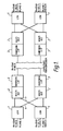
- Referring to Figure 1, a duplicated transmission system is shown comprising a first plane,
PLANE 0 and a second plane, PLANE1. each carrying 16 x 2048 kbit/s. - Each plane at each end of the transmission line includes a line control multiplexer, 1 connected to a multi digital line termination unit, 2 which is interfaced to the transmission line by
transmission interface equipment 3. The multi digitalline termination unit 2 and theline control multiplexer 1, are used to provide the scissors crossover protection by use ofpaths line termination unit 2. - In the environment of System X, the digital line termination units constantly monitor line alarm conditions, such as input loss, loss of frame alignment, high error rate, and all 1's condition.
- A subsystem known as the digital switching subsystem controls the digital line termination units. It receives the monitored alarm conditions and decides when a path is becoming unacceptable for transmission and instructs the respective digital line termination unit to switch to the standby route. An article by A.S. Philip, entitled The System X Digital Switching Subsystem (DSS), Systems Technology
No 32, September 1979 atpage 5 describes the digital switching subsystem in detail, and discusses digital line termination units. - The line control multiplexer distributes clock, synchronised 2Mbit speech data and control sync signals. It basically provides a number of fanout circuits.
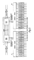
- Referring to Figure 2, the scissors crossover principle can be used in transmission rings to take advantage of the case of tributary configuration. Figure 2 shows two configurations superimposed and configured as a ring. The scissors crossover is shown as
paths line control multiplexers 1 and the multi digitalline termination units 2. - If the ring is broken at X then application A is still connected to the main switch via the upper route, while application B is still connected via the lower route. It is very important to be able to protection select at the tributary level.
- At each attachment point to the ring it is necessary to have an Add and Drop Multiplexer, 6-8 because only some of the tributaries are terminated at any attachment point.
- The Add and Drop Multiplexer (ADMX) 6 has to be connected to the scissors crossover function. The Add and Drop Multiplexer is arranged to add and drop the required tributaries and pass these tributaries via the Intermediate Interface to the scissors crossover function main switch.
- Where
ordinary type 2048/1544 kbit/s interfaces are required then the scissors crossover function is replaced by tributary multiplexer/demultiplexers 9-12. There are two arrangements shown in Figure 2, (A) where an unsecured tributary interface is required and protection has to be done external to the application byunit 13 and (B), where the application contains the protection switching function. A more detailed arrangement of the tributary interface is shown in Figure 3. - In Figure 3, the ADMX 7 corresponds to that shown as 7 in Figure 2, for example, and the fanout/
fanin circuits 17,18 and the HDB3 circuits 16, correspond to the tributary multiplexer/demultiplexer circuits 9,10 of Figure 2, for example. Some applications can be attached to the Intermediate Interfaces without the need for the low bit rate interfaces. - The division of control between the ring and the attached applications, including the main switch, can be very conveniently drawn at the Intermediate Interface. The ring control looks after the connection of a pair of tributaries between the applications. The receiving application, whether using conventional protection switching or a scissors crossover, decides which of the pair of tributaries is the worker and which is the standby. The slip units of the ADMX will independently use the transport fault detection mechanisms to decide the best clock to use and alarm any area not performing to standard. Alarms are reported around the ring to the Master ADMX. The Master ADMX is usually the one which receives the Network Clock.
- Each slip unit of an ADMX is able to extract control messages carried by the transport overhead of both counter rotating ring transmission systems, from the Master ADMX. These messages, if validated, are used to change the column interchange switch selections and other administration functions.
- The security timing and switching of the ADMX, 6-8 will now be described in detail. The bit rate of the ring is assumed to be 155.52 Mbit/s although the principles will equally apply to higher or lower multiple bit rates.
- Each ADMX consist of two identical "Slip Units", 14,15 as shown in Figure 2. Traffic is slipped to and from the upper 155.52 Mbit/s Synchronous Stream by Slip Unit, 14 and traffic is slipped to and from the lower 155 Mbit/s Synchronous Stream by Slip Unit, 15.
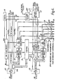
- The ADMX is able to have a multiplicity of Intermediate Interfaces. The number will depend on the total amount of bandwidth to be attached, and the number of separate equipments of lower order multiplexers that must be attached. The general arrangement for one slip unit (half an ADMX) is shown in Figure 4.
- A pair of slip units, usually the pair attached to the switch in the exchange, are supplied with a network clock which they use for their respective transmission interfaces. These clocks are transmitted around the ring in opposite directions. At the other pairs of slip units around the ring, the clock received by one slip unit of a pair is normally used by the other one of that pair to transmit around the ring. The same clock is also divided and used for the Intermediate Interface. Under fault conditions, when a slip unit cannot use its transmit normal clock it will use its own received clock, or if that is suspect then its standby crystal, 14.
- Receive clock selection is made by circuit, 20, and the transmit clock selection by
circuit 21. - At the receiving end of an Intermediate Interface there is a rejustifier, 15. This transfers the payload from the timing reference of the transmitting end to the timing reference of the receiving end.
- Rejustification is used where no critical data loss is permissible. The input or output stream, or both, contain additional data in addition to the critical data. The additional data is used to fill up the data stream to the standard size and to indicate what data is critical data and what is additional data.
- A slip unit must rejustify all its received Intermediate Interfaces to the ring timing used by its 155.52 Mbit/s transmit interface.
- An ADMX has to rejustify between slip unit pairs which are supplied by the network clock. In practice all pairs have to rejustify in order to simplify the return from a standby clock after a fault. This rejustification is a complete payload rejustification.
- A slip unit is required to take any combination of tributaries, from the 155 Mbit/s ring interface, and pass the tributaries in a defined order to an Intermediate Interface, provided that the total bandwidth of the tributaries is within the bandwidth capability of the Intermediate Interface. A tributary is carried by several 9 byte columns. The column
interchange switch function - The advantage of having a tributary switching function within the ADMX is to minimise the number of tributary interfaces that have to be provided and still offer a very flexible arrangement. In order to allow for a multiplicity of Intermediate Interfaces, the rate adaption function is required to group the tributaries into several lower speed byte streams. This is a straight forward function as the column interchange switch, 22,32 puts the tributaries into a convenient order for grouping.
- The 155.52 Mbit/s signals are received by an
optical interface 23 and passed to the other slip unit of the ADMX. Clock information is extracted bycircuit 20 and control information by thecontrol circuits - Data is processed by the
column interchange switch 22,bit rate adapter 25, and is outputted to the intermediate interfaces byoptic transmitters 26. - Clock, control and data information is received from the other slip unit in the ADMX and processed by a
payload retimer 27. The data and clock information is passed to aselector circuit 28, and the control information is passed to controlcircuit 24b. Incoming data from the intermediate interfaces is received byoptic transmitters 29 and is processed byrejustifier circuits 30, bitrate adaptor circuit 31 and thecolumn interchange switch 32 before being presented to theselector circuit 28. The bitrate adaptor circuit 31 andcolumn interchange switch 32 are controlled bycontrol circuit 24. Theselector circuit 28, passes the selected data to the transmitoptic interface 33 which is controlled bycircuit 24b. - The invention is not intended to be limited to the embodiments described above. The invention can be applied to any two plane switching arrangement where security is required. For example, the invention could be used in an automatic digital distribution frame where electrical or optical links can be reconfigured at the distribution frame automatically, with security being provided by the scissors crossover technique at each switching stage of the automatic distribution frame. Also, different transmission rates than those disclosed could also be used.
Claims (7)
Applications Claiming Priority (2)
| Application Number | Priority Date | Filing Date | Title |
|---|---|---|---|
| GB8819470 | 1988-08-16 | ||
| GB8819470A GB2222055B (en) | 1988-08-16 | 1988-08-16 | Telecommunications transmission security arrangement |
Publications (3)
| Publication Number | Publication Date |
|---|---|
| EP0359352A2 true EP0359352A2 (en) | 1990-03-21 |
| EP0359352A3 EP0359352A3 (en) | 1992-08-26 |
| EP0359352B1 EP0359352B1 (en) | 1999-10-13 |
Family
ID=10642218
Family Applications (1)
| Application Number | Title | Priority Date | Filing Date |
|---|---|---|---|
| EP89303154A Expired - Lifetime EP0359352B1 (en) | 1988-08-16 | 1989-03-30 | Telecommunications transmission security arrangement |
Country Status (12)
| Country | Link |
|---|---|
| US (1) | US5091902A (en) |
| EP (1) | EP0359352B1 (en) |
| JP (1) | JPH0276428A (en) |
| KR (1) | KR900004128A (en) |
| CN (1) | CN1018227B (en) |
| DE (1) | DE68929085T2 (en) |
| DK (1) | DK402389A (en) |
| ES (1) | ES2136592T3 (en) |
| FI (1) | FI893848A (en) |
| GB (1) | GB2222055B (en) |
| IN (1) | IN172258B (en) |
| PT (1) | PT91377A (en) |
Cited By (9)
| Publication number | Priority date | Publication date | Assignee | Title |
|---|---|---|---|---|
| EP0505062A2 (en) * | 1991-03-22 | 1992-09-23 | Gpt Limited | Multiplex data ring transmission |
| EP0570882A2 (en) * | 1992-05-21 | 1993-11-24 | Alcatel N.V. | A distributed control methodology and mechanism for implementing automatic protection switching |
| US5436886A (en) * | 1994-07-14 | 1995-07-25 | Northern Telecom Limited | ATM switch in dual switch plane operation |
| WO1997024900A1 (en) * | 1995-12-29 | 1997-07-10 | Mci Communications Corporation | Method and system for optical restoration tributary switching in a fiber network |
| US5731887A (en) * | 1995-12-22 | 1998-03-24 | Mci Communications Corporation | System and method for photonic facility and line protection switching |
| US5777761A (en) * | 1995-12-22 | 1998-07-07 | Mci Communications Corporation | System and method for photonic facility and line protection switching using wavelength translation |
| US5903370A (en) * | 1996-06-28 | 1999-05-11 | Mci Communications Corporation | System for an optical domain |
| US6108113A (en) * | 1995-12-29 | 2000-08-22 | Mci Communications Corporation | Method and system for transporting ancillary network data |
| US6285475B1 (en) | 1995-12-29 | 2001-09-04 | Mci Communications Corporation | Method and system for detecting optical faults in a network fiber link |
Families Citing this family (10)
| Publication number | Priority date | Publication date | Assignee | Title |
|---|---|---|---|---|
| GB9010603D0 (en) * | 1990-05-11 | 1990-07-04 | Int Computers Ltd | Access control in a distributed computer system |
| JP2663687B2 (en) * | 1990-07-27 | 1997-10-15 | 日本電気株式会社 | ATM communication system in dual ring network |
| US5454025A (en) * | 1992-11-12 | 1995-09-26 | Mulrow; Robert J. | Switch bypass for a public safety calling system |
| CA2107755C (en) * | 1992-11-16 | 1998-07-07 | Paul Elliott Janssen | Telecommunication system with improved reconfiguration flexibility |
| DE4331577C2 (en) * | 1993-09-16 | 1995-12-07 | Siemens Ag | Method and circuit arrangement for transmitting message cells via redundant virtual path pairs of an ATM communication network |
| US6005694A (en) * | 1995-12-28 | 1999-12-21 | Mci Worldcom, Inc. | Method and system for detecting optical faults within the optical domain of a fiber communication network |
| JP3531526B2 (en) * | 1999-05-13 | 2004-05-31 | 日本電気株式会社 | Communications system |
| US6914878B1 (en) | 2000-10-16 | 2005-07-05 | Telefonaktiebolaget Lm Ericsson (Publ) | Fault detection in multi-plane switch |
| JP4562900B2 (en) * | 2000-11-30 | 2010-10-13 | パナソニック株式会社 | Transmission device and remote control system |
| EP2621135B1 (en) * | 2012-01-24 | 2018-06-13 | ADVA Optical Networking SE | A method and a system for providing a flexible secondary data path |
Citations (1)
| Publication number | Priority date | Publication date | Assignee | Title |
|---|---|---|---|---|
| US4648088A (en) * | 1985-08-19 | 1987-03-03 | Rockwell International Corporation | Distributed control time division multiplex ring communication apparatus |
Family Cites Families (10)
| Publication number | Priority date | Publication date | Assignee | Title |
|---|---|---|---|---|
| JPS5412766B2 (en) * | 1971-11-24 | 1979-05-25 | ||
| US4076961A (en) * | 1974-09-23 | 1978-02-28 | Intertel, Inc. | Automatic switching unit for data communications network |
| JPS55136742A (en) * | 1979-04-13 | 1980-10-24 | Toshiba Corp | Multiplex communication system |
| US4385392A (en) * | 1981-07-31 | 1983-05-24 | Angell Gary W | Modem fault detector and corrector system |
| AU552312B2 (en) * | 1982-02-08 | 1986-05-29 | Racal-Milgo Limited | Communication system |
| US4633246A (en) * | 1984-01-09 | 1986-12-30 | Fiberlan, Inc. | Time divison multiplex ring |
| GB2165412B (en) * | 1984-10-05 | 1988-08-10 | Stc Plc | Improvements in optical transmission systems |
| US4694492A (en) * | 1984-11-09 | 1987-09-15 | Pirmasafe, Inc. | Computer communications security control system |
| EP0194674B1 (en) * | 1985-03-12 | 1992-06-24 | Honda Giken Kogyo Kabushiki Kaisha | Multiplex transmission system |
| US4680771A (en) * | 1985-12-31 | 1987-07-14 | Amada Engineering Service Co., Inc. | Mirror adjustment device in laser oscillator |
-
1988
- 1988-08-16 GB GB8819470A patent/GB2222055B/en not_active Expired - Lifetime
-
1989
- 1989-03-30 DE DE68929085T patent/DE68929085T2/en not_active Expired - Lifetime
- 1989-03-30 ES ES89303154T patent/ES2136592T3/en not_active Expired - Lifetime
- 1989-03-30 EP EP89303154A patent/EP0359352B1/en not_active Expired - Lifetime
- 1989-04-13 IN IN279MA1989 patent/IN172258B/en unknown
- 1989-04-26 KR KR1019890005497A patent/KR900004128A/en not_active Application Discontinuation
- 1989-05-06 CN CN89103060A patent/CN1018227B/en not_active Expired
- 1989-06-05 JP JP1141304A patent/JPH0276428A/en active Pending
- 1989-08-03 PT PT91377A patent/PT91377A/en not_active Application Discontinuation
- 1989-08-15 FI FI893848A patent/FI893848A/en not_active IP Right Cessation
- 1989-08-16 DK DK402389A patent/DK402389A/en not_active Application Discontinuation
-
1990
- 1990-05-24 US US07/529,686 patent/US5091902A/en not_active Expired - Lifetime
Patent Citations (1)
| Publication number | Priority date | Publication date | Assignee | Title |
|---|---|---|---|---|
| US4648088A (en) * | 1985-08-19 | 1987-03-03 | Rockwell International Corporation | Distributed control time division multiplex ring communication apparatus |
Non-Patent Citations (3)
| Title |
|---|
| GLOBECOM '86, SESSION 33, PAPER 5 vol. 2, 1 December 1986, HOUSTON US pages 1 - 5; T. WAKABAYASHI ET AL.: 'A Synchronous DS3 ADD/Drop Multiplexer with Cross-Connect' * |
| INTERNATIONAL SWITCHING SYMPOSIUM 1987, SESSION B2, PAPER 2 vol. 1, 15 March 1987, PHOENIX US pages 1 - 6; M.A.KOLLMORGEN ET AL.: 'Exploiting the Power of Common Channel Signaling System No. 7: Network Capabilities and New Signaling Network Switching Technology' * |
| INTERNATIONAL SYMPOSIUM ON SUBSCRIBER LOOPS AND SERVICES, SESSION 9, PAPER 3 11 September 1988, BOSTON US pages 1 - 5; G.CHOPPING ET AL.: 'Transmission Protection and Interfacing in the Synchronous Local Network' * |
Cited By (14)
| Publication number | Priority date | Publication date | Assignee | Title |
|---|---|---|---|---|
| EP0505062A3 (en) * | 1991-03-22 | 1993-04-28 | Gpt Limited | Multiplex data ring transmission |
| EP0505062A2 (en) * | 1991-03-22 | 1992-09-23 | Gpt Limited | Multiplex data ring transmission |
| US5740157A (en) * | 1992-05-21 | 1998-04-14 | Alcatel Network Systems, Inc. | Distributed control methodology and mechanism for implementing automatic protection switching |
| EP0570882A2 (en) * | 1992-05-21 | 1993-11-24 | Alcatel N.V. | A distributed control methodology and mechanism for implementing automatic protection switching |
| EP0570882A3 (en) * | 1992-05-21 | 1995-07-19 | Alcatel Nv | A distributed control methodology and mechanism for implementing automatic protection switching. |
| US5436886A (en) * | 1994-07-14 | 1995-07-25 | Northern Telecom Limited | ATM switch in dual switch plane operation |
| WO1996002994A1 (en) * | 1994-07-14 | 1996-02-01 | Northern Telecom Limited | Atm switch in dual switch plane operation |
| US5777761A (en) * | 1995-12-22 | 1998-07-07 | Mci Communications Corporation | System and method for photonic facility and line protection switching using wavelength translation |
| US5731887A (en) * | 1995-12-22 | 1998-03-24 | Mci Communications Corporation | System and method for photonic facility and line protection switching |
| WO1997024900A1 (en) * | 1995-12-29 | 1997-07-10 | Mci Communications Corporation | Method and system for optical restoration tributary switching in a fiber network |
| US5884017A (en) * | 1995-12-29 | 1999-03-16 | Mci Communications Corporation | Method and system for optical restoration tributary switching in a fiber network |
| US6108113A (en) * | 1995-12-29 | 2000-08-22 | Mci Communications Corporation | Method and system for transporting ancillary network data |
| US6285475B1 (en) | 1995-12-29 | 2001-09-04 | Mci Communications Corporation | Method and system for detecting optical faults in a network fiber link |
| US5903370A (en) * | 1996-06-28 | 1999-05-11 | Mci Communications Corporation | System for an optical domain |
Also Published As
| Publication number | Publication date |
|---|---|
| KR900004128A (en) | 1990-03-27 |
| FI893848A (en) | 1990-02-17 |
| DE68929085D1 (en) | 1999-11-18 |
| PT91377A (en) | 1990-03-08 |
| IN172258B (en) | 1993-05-22 |
| FI893848A0 (en) | 1989-08-15 |
| US5091902A (en) | 1992-02-25 |
| GB8819470D0 (en) | 1988-09-21 |
| JPH0276428A (en) | 1990-03-15 |
| CN1018227B (en) | 1992-09-09 |
| DK402389A (en) | 1990-02-17 |
| ES2136592T3 (en) | 1999-12-01 |
| EP0359352B1 (en) | 1999-10-13 |
| DE68929085T2 (en) | 2000-02-03 |
| GB2222055B (en) | 1992-10-28 |
| CN1040468A (en) | 1990-03-14 |
| EP0359352A3 (en) | 1992-08-26 |
| GB2222055A (en) | 1990-02-21 |
| DK402389D0 (en) | 1989-08-16 |
Similar Documents
| Publication | Publication Date | Title |
|---|---|---|
| US5091902A (en) | Telecommunications transmission security arrangement | |
| EP0548648B1 (en) | 1:N Ring-type signal protection apparatus | |
| EP0559090B1 (en) | Network element comprising a cross-connect matrix and a server | |
| US6317426B1 (en) | Method and apparatus for hybrid protection in a switching network | |
| US5365510A (en) | Communications system with a single protection loop | |
| JP3803974B2 (en) | Integrated multi-structure digital cross-connect integrated office link | |
| US5406401A (en) | Apparatus and method for selective tributary switching in a bidirectional ring transmission system | |
| EP0857401B1 (en) | Broadband digital cross-connect system | |
| JPH07212382A (en) | Communication system | |
| US7313088B2 (en) | Common protection architecture for optical network | |
| JPH07212385A (en) | Communication system | |
| JPH06284141A (en) | Bi-directional transmission line changeover ring network | |
| JP3442180B2 (en) | Add-drop multiplex equipment | |
| EP0741933B1 (en) | Sdh add-drop multiplexer | |
| KR100256689B1 (en) | Add drop multiplexer optical transmission apparatus | |
| AU665655B2 (en) | Dual connections | |
| US7158720B1 (en) | Optical shared protection ring for multiple spans | |
| EP0638223B1 (en) | A method and a cross-connection architecture for error-free change-over of a cross-connection matrix | |
| CA1279132C (en) | Ring transmission system | |
| EP0950336A2 (en) | Method and apparatus to interconnect two or more cross-connects into a single pcm network | |
| KR19990042385A (en) | Branch and combined control device using control signal | |
| JPH1022961A (en) | 1-to-n optical line switch system using adm device | |
| JP2000013349A (en) | Transmission rate conversion method and device | |
| JP2001501423A (en) | Ring circuit with transport loop and card protection |
Legal Events
| Date | Code | Title | Description |
|---|---|---|---|
| PUAI | Public reference made under article 153(3) epc to a published international application that has entered the european phase |
Free format text: ORIGINAL CODE: 0009012 |
|
| AK | Designated contracting states |
Kind code of ref document: A2 Designated state(s): BE DE ES FR GR IT LU NL SE |
|
| PUAL | Search report despatched |
Free format text: ORIGINAL CODE: 0009013 |
|
| AK | Designated contracting states |
Kind code of ref document: A3 Designated state(s): BE DE ES FR GR IT LU NL SE |
|
| 17P | Request for examination filed |
Effective date: 19930210 |
|
| 17Q | First examination report despatched |
Effective date: 19941223 |
|
| RAP1 | Party data changed (applicant data changed or rights of an application transferred) |
Owner name: GPT LIMITED |
|
| GRAG | Despatch of communication of intention to grant |
Free format text: ORIGINAL CODE: EPIDOS AGRA |
|
| GRAG | Despatch of communication of intention to grant |
Free format text: ORIGINAL CODE: EPIDOS AGRA |
|
| GRAH | Despatch of communication of intention to grant a patent |
Free format text: ORIGINAL CODE: EPIDOS IGRA |
|
| RAP1 | Party data changed (applicant data changed or rights of an application transferred) |
Owner name: MARCONI COMMUNICATIONS LIMITED |
|
| GRAH | Despatch of communication of intention to grant a patent |
Free format text: ORIGINAL CODE: EPIDOS IGRA |
|
| GRAA | (expected) grant |
Free format text: ORIGINAL CODE: 0009210 |
|
| AK | Designated contracting states |
Kind code of ref document: B1 Designated state(s): BE DE ES FR GR IT LU NL SE |
|
| PG25 | Lapsed in a contracting state [announced via postgrant information from national office to epo] |
Ref country code: GR Free format text: LAPSE BECAUSE OF NON-PAYMENT OF DUE FEES Effective date: 19991013 Ref country code: SE Free format text: THE PATENT HAS BEEN ANNULLED BY A DECISION OF A NATIONAL AUTHORITY Effective date: 19991013 |
|
| ITF | It: translation for a ep patent filed |
Owner name: JACOBACCI & PERANI S.P.A. |
|
| ET | Fr: translation filed | ||
| REF | Corresponds to: |
Ref document number: 68929085 Country of ref document: DE Date of ref document: 19991118 |
|
| REG | Reference to a national code |
Ref country code: ES Ref legal event code: FG2A Ref document number: 2136592 Country of ref document: ES Kind code of ref document: T3 |
|
| PG25 | Lapsed in a contracting state [announced via postgrant information from national office to epo] |
Ref country code: LU Free format text: LAPSE BECAUSE OF NON-PAYMENT OF DUE FEES Effective date: 20000330 |
|
| PLBE | No opposition filed within time limit |
Free format text: ORIGINAL CODE: 0009261 |
|
| STAA | Information on the status of an ep patent application or granted ep patent |
Free format text: STATUS: NO OPPOSITION FILED WITHIN TIME LIMIT |
|
| 26N | No opposition filed | ||
| PGFP | Annual fee paid to national office [announced via postgrant information from national office to epo] |
Ref country code: ES Payment date: 20020315 Year of fee payment: 14 |
|
| PGFP | Annual fee paid to national office [announced via postgrant information from national office to epo] |
Ref country code: BE Payment date: 20020527 Year of fee payment: 14 |
|
| PG25 | Lapsed in a contracting state [announced via postgrant information from national office to epo] |
Ref country code: BE Free format text: LAPSE BECAUSE OF NON-PAYMENT OF DUE FEES Effective date: 20030331 Ref country code: ES Free format text: LAPSE BECAUSE OF NON-PAYMENT OF DUE FEES Effective date: 20030331 |
|
| BERE | Be: lapsed |
Owner name: *MARCONI COMMUNICATIONS LTD Effective date: 20030331 |
|
| NLS | Nl: assignments of ep-patents |
Owner name: MARCONI UK INTELLECTUAL PROPERTY LTD |
|
| REG | Reference to a national code |
Ref country code: FR Ref legal event code: TP |
|
| REG | Reference to a national code |
Ref country code: ES Ref legal event code: FD2A Effective date: 20030331 |
|
| NLS | Nl: assignments of ep-patents |
Owner name: ERICSSON AB Effective date: 20060802 Owner name: M (DGP1) LTD Effective date: 20060802 |
|
| REG | Reference to a national code |
Ref country code: FR Ref legal event code: TP |
|
| PGFP | Annual fee paid to national office [announced via postgrant information from national office to epo] |
Ref country code: NL Payment date: 20080324 Year of fee payment: 20 |
|
| PGFP | Annual fee paid to national office [announced via postgrant information from national office to epo] |
Ref country code: FR Payment date: 20080317 Year of fee payment: 20 Ref country code: DE Payment date: 20080430 Year of fee payment: 20 |
|
| PGFP | Annual fee paid to national office [announced via postgrant information from national office to epo] |
Ref country code: IT Payment date: 20080329 Year of fee payment: 20 |
|
| PG25 | Lapsed in a contracting state [announced via postgrant information from national office to epo] |
Ref country code: NL Free format text: LAPSE BECAUSE OF EXPIRATION OF PROTECTION Effective date: 20090330 |
|
| NLV7 | Nl: ceased due to reaching the maximum lifetime of a patent |
Effective date: 20090330 |