EP0362397A1 - Heater-fumigator - Google Patents
Heater-fumigator Download PDFInfo
- Publication number
- EP0362397A1 EP0362397A1 EP89902287A EP89902287A EP0362397A1 EP 0362397 A1 EP0362397 A1 EP 0362397A1 EP 89902287 A EP89902287 A EP 89902287A EP 89902287 A EP89902287 A EP 89902287A EP 0362397 A1 EP0362397 A1 EP 0362397A1
- Authority
- EP
- European Patent Office
- Prior art keywords
- vaporizer
- bottle
- heater
- chemical
- thermal
- Prior art date
- Legal status (The legal status is an assumption and is not a legal conclusion. Google has not performed a legal analysis and makes no representation as to the accuracy of the status listed.)
- Granted
Links
- 239000000126 substance Substances 0.000 claims abstract description 44
- 238000010438 heat treatment Methods 0.000 claims abstract description 7
- 239000006200 vaporizer Substances 0.000 claims description 38
- 238000009835 boiling Methods 0.000 claims description 11
- 239000002904 solvent Substances 0.000 claims description 6
- 238000004891 communication Methods 0.000 claims description 2
- 230000008878 coupling Effects 0.000 abstract 1
- 238000010168 coupling process Methods 0.000 abstract 1
- 238000005859 coupling reaction Methods 0.000 abstract 1
- 238000009834 vaporization Methods 0.000 description 10
- 230000008016 vaporization Effects 0.000 description 10
- 150000001338 aliphatic hydrocarbons Chemical class 0.000 description 9
- 239000002917 insecticide Substances 0.000 description 9
- 239000007788 liquid Substances 0.000 description 9
- VYPSYNLAJGMNEJ-UHFFFAOYSA-N Silicium dioxide Chemical compound O=[Si]=O VYPSYNLAJGMNEJ-UHFFFAOYSA-N 0.000 description 7
- OKTJSMMVPCPJKN-UHFFFAOYSA-N Carbon Chemical compound [C] OKTJSMMVPCPJKN-UHFFFAOYSA-N 0.000 description 6
- 235000013312 flour Nutrition 0.000 description 6
- 239000000203 mixture Substances 0.000 description 6
- 239000002023 wood Substances 0.000 description 6
- 239000000843 powder Substances 0.000 description 5
- 230000000052 comparative effect Effects 0.000 description 4
- 239000003292 glue Substances 0.000 description 4
- 241000255925 Diptera Species 0.000 description 3
- 238000010521 absorption reaction Methods 0.000 description 3
- 230000001276 controlling effect Effects 0.000 description 3
- 229910052500 inorganic mineral Inorganic materials 0.000 description 3
- 230000000749 insecticidal effect Effects 0.000 description 3
- 239000000463 material Substances 0.000 description 3
- 239000011707 mineral Substances 0.000 description 3
- 239000003921 oil Substances 0.000 description 3
- XLYOFNOQVPJJNP-UHFFFAOYSA-N water Substances O XLYOFNOQVPJJNP-UHFFFAOYSA-N 0.000 description 3
- XLOPRKKSAJMMEW-SFYZADRCSA-M (R,R)-chrysanthemate Chemical compound CC(C)=C[C@@H]1[C@@H](C([O-])=O)C1(C)C XLOPRKKSAJMMEW-SFYZADRCSA-M 0.000 description 2
- OSDLLIBGSJNGJE-UHFFFAOYSA-N 4-chloro-3,5-dimethylphenol Chemical compound CC1=CC(O)=CC(C)=C1Cl OSDLLIBGSJNGJE-UHFFFAOYSA-N 0.000 description 2
- HEDRZPFGACZZDS-UHFFFAOYSA-N Chloroform Chemical compound ClC(Cl)Cl HEDRZPFGACZZDS-UHFFFAOYSA-N 0.000 description 2
- NIQCNGHVCWTJSM-UHFFFAOYSA-N Dimethyl phthalate Chemical compound COC(=O)C1=CC=CC=C1C(=O)OC NIQCNGHVCWTJSM-UHFFFAOYSA-N 0.000 description 2
- UFWIBTONFRDIAS-UHFFFAOYSA-N Naphthalene Chemical compound C1=CC=CC2=CC=CC=C21 UFWIBTONFRDIAS-UHFFFAOYSA-N 0.000 description 2
- 229920002472 Starch Polymers 0.000 description 2
- PNEYBMLMFCGWSK-UHFFFAOYSA-N aluminium oxide Inorganic materials [O-2].[O-2].[O-2].[Al+3].[Al+3] PNEYBMLMFCGWSK-UHFFFAOYSA-N 0.000 description 2
- 230000000844 anti-bacterial effect Effects 0.000 description 2
- 239000010425 asbestos Substances 0.000 description 2
- 239000003899 bactericide agent Substances 0.000 description 2
- 230000008901 benefit Effects 0.000 description 2
- 239000000440 bentonite Substances 0.000 description 2
- 229910000278 bentonite Inorganic materials 0.000 description 2
- SVPXDRXYRYOSEX-UHFFFAOYSA-N bentoquatam Chemical compound O.O=[Si]=O.O=[Al]O[Al]=O SVPXDRXYRYOSEX-UHFFFAOYSA-N 0.000 description 2
- 239000004927 clay Substances 0.000 description 2
- 239000002781 deodorant agent Substances 0.000 description 2
- 238000001035 drying Methods 0.000 description 2
- 239000000417 fungicide Substances 0.000 description 2
- 230000005484 gravity Effects 0.000 description 2
- 238000007373 indentation Methods 0.000 description 2
- 239000000077 insect repellent Substances 0.000 description 2
- 238000004898 kneading Methods 0.000 description 2
- -1 medicinals Substances 0.000 description 2
- 238000000465 moulding Methods 0.000 description 2
- 239000012188 paraffin wax Substances 0.000 description 2
- 239000010451 perlite Substances 0.000 description 2
- 235000019362 perlite Nutrition 0.000 description 2
- BASFCYQUMIYNBI-UHFFFAOYSA-N platinum Chemical compound [Pt] BASFCYQUMIYNBI-UHFFFAOYSA-N 0.000 description 2
- 230000002035 prolonged effect Effects 0.000 description 2
- 230000001681 protective effect Effects 0.000 description 2
- 239000005871 repellent Substances 0.000 description 2
- 230000002940 repellent Effects 0.000 description 2
- 229910052895 riebeckite Inorganic materials 0.000 description 2
- 239000000741 silica gel Substances 0.000 description 2
- 229910002027 silica gel Inorganic materials 0.000 description 2
- 239000000377 silicon dioxide Substances 0.000 description 2
- 239000007787 solid Substances 0.000 description 2
- 239000008107 starch Substances 0.000 description 2
- 235000019698 starch Nutrition 0.000 description 2
- 239000004308 thiabendazole Substances 0.000 description 2
- 235000010296 thiabendazole Nutrition 0.000 description 2
- WJCNZQLZVWNLKY-UHFFFAOYSA-N thiabendazole Chemical compound S1C=NC(C=2NC3=CC=CC=C3N=2)=C1 WJCNZQLZVWNLKY-UHFFFAOYSA-N 0.000 description 2
- 229960004546 thiabendazole Drugs 0.000 description 2
- OCJBOOLMMGQPQU-UHFFFAOYSA-N 1,4-dichlorobenzene Chemical compound ClC1=CC=C(Cl)C=C1 OCJBOOLMMGQPQU-UHFFFAOYSA-N 0.000 description 1
- YPZMPEPLWKRVLD-UHFFFAOYSA-N 2,3,4,5,6,7-hexahydroxyheptanal Chemical compound OCC(O)C(O)C(O)C(O)C(O)C=O YPZMPEPLWKRVLD-UHFFFAOYSA-N 0.000 description 1
- 244000215068 Acacia senegal Species 0.000 description 1
- 239000005995 Aluminium silicate Substances 0.000 description 1
- 229920002134 Carboxymethyl cellulose Polymers 0.000 description 1
- 229920000742 Cotton Polymers 0.000 description 1
- 239000004287 Dehydroacetic acid Substances 0.000 description 1
- 239000004375 Dextrin Substances 0.000 description 1
- 229920001353 Dextrin Polymers 0.000 description 1
- YUGWDVYLFSETPE-JLHYYAGUSA-N Empenthrin Chemical compound CC\C=C(/C)C(C#C)OC(=O)C1C(C=C(C)C)C1(C)C YUGWDVYLFSETPE-JLHYYAGUSA-N 0.000 description 1
- LFQSCWFLJHTTHZ-UHFFFAOYSA-N Ethanol Chemical compound CCO LFQSCWFLJHTTHZ-UHFFFAOYSA-N 0.000 description 1
- 229920000084 Gum arabic Polymers 0.000 description 1
- MMOXZBCLCQITDF-UHFFFAOYSA-N N,N-diethyl-m-toluamide Chemical compound CCN(CC)C(=O)C1=CC=CC(C)=C1 MMOXZBCLCQITDF-UHFFFAOYSA-N 0.000 description 1
- ISRUGXGCCGIOQO-UHFFFAOYSA-N Rhoden Chemical compound CNC(=O)OC1=CC=CC=C1OC(C)C ISRUGXGCCGIOQO-UHFFFAOYSA-N 0.000 description 1
- 241000283984 Rodentia Species 0.000 description 1
- RTAQQCXQSZGOHL-UHFFFAOYSA-N Titanium Chemical compound [Ti] RTAQQCXQSZGOHL-UHFFFAOYSA-N 0.000 description 1
- 239000000205 acacia gum Substances 0.000 description 1
- 235000010489 acacia gum Nutrition 0.000 description 1
- 239000000642 acaricide Substances 0.000 description 1
- 239000000654 additive Substances 0.000 description 1
- 235000012211 aluminium silicate Nutrition 0.000 description 1
- 239000003963 antioxidant agent Substances 0.000 description 1
- 239000011230 binding agent Substances 0.000 description 1
- 235000015895 biscuits Nutrition 0.000 description 1
- 239000001768 carboxy methyl cellulose Substances 0.000 description 1
- 235000010948 carboxy methyl cellulose Nutrition 0.000 description 1
- 239000008112 carboxymethyl-cellulose Substances 0.000 description 1
- 239000003054 catalyst Substances 0.000 description 1
- 239000003795 chemical substances by application Substances 0.000 description 1
- 239000010632 citronella oil Substances 0.000 description 1
- 239000002537 cosmetic Substances 0.000 description 1
- 239000001941 cymbopogon citratus dc and cymbopogon flexuosus oil Substances 0.000 description 1
- 230000007547 defect Effects 0.000 description 1
- 235000019258 dehydroacetic acid Nutrition 0.000 description 1
- 229940061632 dehydroacetic acid Drugs 0.000 description 1
- JEQRBTDTEKWZBW-UHFFFAOYSA-N dehydroacetic acid Chemical compound CC(=O)C1=C(O)OC(C)=CC1=O JEQRBTDTEKWZBW-UHFFFAOYSA-N 0.000 description 1
- PGRHXDWITVMQBC-UHFFFAOYSA-N dehydroacetic acid Natural products CC(=O)C1C(=O)OC(C)=CC1=O PGRHXDWITVMQBC-UHFFFAOYSA-N 0.000 description 1
- 238000000151 deposition Methods 0.000 description 1
- 235000019425 dextrin Nutrition 0.000 description 1
- FBSAITBEAPNWJG-UHFFFAOYSA-N dimethyl phthalate Natural products CC(=O)OC1=CC=CC=C1OC(C)=O FBSAITBEAPNWJG-UHFFFAOYSA-N 0.000 description 1
- 229960001826 dimethylphthalate Drugs 0.000 description 1
- 230000003292 diminished effect Effects 0.000 description 1
- GMSCBRSQMRDRCD-UHFFFAOYSA-N dodecyl 2-methylprop-2-enoate Chemical compound CCCCCCCCCCCCOC(=O)C(C)=C GMSCBRSQMRDRCD-UHFFFAOYSA-N 0.000 description 1
- BNKAXGCRDYRABM-UHFFFAOYSA-N ethenyl dihydrogen phosphate Chemical compound OP(O)(=O)OC=C BNKAXGCRDYRABM-UHFFFAOYSA-N 0.000 description 1
- BEFDCLMNVWHSGT-UHFFFAOYSA-N ethenylcyclopentane Chemical compound C=CC1CCCC1 BEFDCLMNVWHSGT-UHFFFAOYSA-N 0.000 description 1
- 238000000605 extraction Methods 0.000 description 1
- 238000004817 gas chromatography Methods 0.000 description 1
- 239000003365 glass fiber Substances 0.000 description 1
- 239000010440 gypsum Substances 0.000 description 1
- 229910052602 gypsum Inorganic materials 0.000 description 1
- 239000004009 herbicide Substances 0.000 description 1
- 230000006872 improvement Effects 0.000 description 1
- 239000003112 inhibitor Substances 0.000 description 1
- 239000012784 inorganic fiber Substances 0.000 description 1
- NLYAJNPCOHFWQQ-UHFFFAOYSA-N kaolin Chemical compound O.O.O=[Al]O[Si](=O)O[Si](=O)O[Al]=O NLYAJNPCOHFWQQ-UHFFFAOYSA-N 0.000 description 1
- 229940107698 malachite green Drugs 0.000 description 1
- FDZZZRQASAIRJF-UHFFFAOYSA-M malachite green Chemical compound [Cl-].C1=CC(N(C)C)=CC=C1C(C=1C=CC=CC=1)=C1C=CC(=[N+](C)C)C=C1 FDZZZRQASAIRJF-UHFFFAOYSA-M 0.000 description 1
- 230000004048 modification Effects 0.000 description 1
- 238000012986 modification Methods 0.000 description 1
- 239000004745 nonwoven fabric Substances 0.000 description 1
- 239000003960 organic solvent Substances 0.000 description 1
- 238000013021 overheating Methods 0.000 description 1
- 230000003647 oxidation Effects 0.000 description 1
- 238000007254 oxidation reaction Methods 0.000 description 1
- 239000002304 perfume Substances 0.000 description 1
- 239000000049 pigment Substances 0.000 description 1
- 230000008635 plant growth Effects 0.000 description 1
- 229910052697 platinum Inorganic materials 0.000 description 1
- 229920001296 polysiloxane Polymers 0.000 description 1
- 229910052573 porcelain Inorganic materials 0.000 description 1
- 239000011148 porous material Substances 0.000 description 1
- SMKRKQBMYOFFMU-UHFFFAOYSA-N prallethrin Chemical compound CC1(C)C(C=C(C)C)C1C(=O)OC1C(C)=C(CC#C)C(=O)C1 SMKRKQBMYOFFMU-UHFFFAOYSA-N 0.000 description 1
- 230000001698 pyrogenic effect Effects 0.000 description 1
- 230000009467 reduction Effects 0.000 description 1
- 230000001105 regulatory effect Effects 0.000 description 1
- 238000009877 rendering Methods 0.000 description 1
- 239000011435 rock Substances 0.000 description 1
- 239000003128 rodenticide Substances 0.000 description 1
- 150000003839 salts Chemical class 0.000 description 1
- 235000010199 sorbic acid Nutrition 0.000 description 1
- 239000004334 sorbic acid Substances 0.000 description 1
- 229940075582 sorbic acid Drugs 0.000 description 1
- 230000002459 sustained effect Effects 0.000 description 1
- 239000000454 talc Substances 0.000 description 1
- 229910052623 talc Inorganic materials 0.000 description 1
- 229960005199 tetramethrin Drugs 0.000 description 1
- CXBMCYHAMVGWJQ-UHFFFAOYSA-N tetramethrin Chemical compound CC1(C)C(C=C(C)C)C1C(=O)OCN1C(=O)C(CCCC2)=C2C1=O CXBMCYHAMVGWJQ-UHFFFAOYSA-N 0.000 description 1
- 229910052719 titanium Inorganic materials 0.000 description 1
- 239000010936 titanium Substances 0.000 description 1
Images


Classifications
-
- A—HUMAN NECESSITIES
- A01—AGRICULTURE; FORESTRY; ANIMAL HUSBANDRY; HUNTING; TRAPPING; FISHING
- A01M—CATCHING, TRAPPING OR SCARING OF ANIMALS; APPARATUS FOR THE DESTRUCTION OF NOXIOUS ANIMALS OR NOXIOUS PLANTS
- A01M1/00—Stationary means for catching or killing insects
- A01M1/20—Poisoning, narcotising, or burning insects
- A01M1/2022—Poisoning or narcotising insects by vaporising an insecticide
- A01M1/2061—Poisoning or narcotising insects by vaporising an insecticide using a heat source
- A01M1/2077—Poisoning or narcotising insects by vaporising an insecticide using a heat source using an electrical resistance as heat source
Definitions
- the present invention relates to devices for thermal vaporization, and more particularly to thermal vaporizers of the so-called cordless type for use as directly attached to electric outlets provided on interior vertical surfaces as of walls, pillars, etc.
- Thermal vaporizers such as electric mosquito controlling devices
- Those of the mat type include cordless devices already proposed, while cordless devices of the liquid type have yet to be proposed.
- the electric mosquito controlling device of the liquid type is relatively heavy in its entirety since the overall weight of the device includes the weight of the device body and that of the solution bottle. If cordless, the entire device must be supported against gravity solely by a plug attached to the electric outlet. It is therefore likely that the plug will slip off the outlet when the device is heavy.
- the conventional electric mosquito controlling device of the liquid type with a cord comprises a box-shaped body and is used with a solution bottle accommodated in the body.
- the device body of the conventional structure must have a height at least sufficient for the body to accommodate the solution bottle and the wick projecting upward from the bottle, and is consequently large-sized, heavy and unsuited for use as a cordless device.
- the device is further inconvenient in that the bottom portion of the device body needs to be removed when the solution bottle is to be accommodated in the body.
- the main object of the present invention is to provide a cordless thermal vaporizer of the liquid type which is usable as attached to an electric outlet reliably with stability.
- Another object of the invention is to provide a cordless thermal vaporizer of the liquid type wherein a chemical solution bottle can be attached to the body of the device easily.
- Still another object of the invention is to provide a thermally vaporizable chemical solution which is usable for a prolonged period of time for thermal vaporization and can therefore be used as contained in a small bottle.
- the present invention provides a cordless thermal vaporizer for use with a plug inserted in an electric outlet, the vaporizer being characterized in that the body of the vaporizer is internally provided with a heater for heating a wick for drawing up a chemical solution from a bottle, and a socket disposed under the heater and removably fittable in the form of a cap to the bottle for attachment thereto.
- the thermal'vaporizer of the present invention is so constructed that the body thereof can be fittingly attached, at its socket in the form of a cap, to the chemical solution bottle. Accordingly, the body is smaller in size, especially in the dimension along the direction of its height, and in weight than the box-shaped conventional one. The reduced weight lessens the burden on the plug blades inserted in the outlet during use, almost completely eliminating the tendency for the plug to slip off the outlet and making the vaporizer usable as attached to the outlet reliably with stability.
- the solution bottle can be attached directly to the socket of the vaporizer body, the bottle is easy to fit in and remove.
- the plug is provided on the rear side of the vaporizer body.
- Electric outlets are divided into two types: the vertical type for use with (two or three) plug blades as arranged vertically, and the horizontal type for use with plug blades as arranged horizontally.
- Either the vertical type or the horizontal type is used in countries depending on the domestic situation.
- the plug is rotatable through an angular range of 0 to 90 degrees relative to the rear side of the body to make the arrangement of the plug blades selectively changeable to the vertical or horizontal direction
- the vaporizer is usable for either one of the two types of outlets, hence convenient.
- the vaporizer body can be provided at its lower end with a skirt for forming a circumferential clearance around the outer periphery of the solution bottle.
- the skirt functions as a protective member for protecting the solution bottle from external impact and further as a cover member for holding the bottle out of sight. Further when the clearance is made to communicate with the interior of the body, an air current flows upward through the clearance into the body, permitting a vapor of chemical to be entrained in the upward air current, whereby the chemical vapor can be diffused effectively.
- the thermally vaporizable chemical solution to be used as contained in the solution bottle according to the invention is a solution of at least one of chemicals such as insecticides, bactericides, repellents, miticides plant growth regulating agents, rodenticides, cosmetics, medicinals, perfumes, deodorants, herbicides, fungicides, insect repellents for clothes, mold inhibitors, etc.
- chemicals such as insecticides, bactericides, repellents, miticides plant growth regulating agents, rodenticides, cosmetics, medicinals, perfumes, deodorants, herbicides, fungicides, insect repellents for clothes, mold inhibitors, etc.
- variatous additives such as synergists and antioxidants are added to the solution.
- these chemicals have a high vapor pressure of at least 3.5 x 10 -8 mm Hg/20°C. Examples of such chemicals are given below.
- Suitable solvents for dissolving the chemical are those having a boiling point of up to 350°C.
- examples of such solvents are water, Deet, alcohol, silicone, aliphatic hydrocarbons, etc.
- Especially suitable aliphatic hydrocarbons are those having a boiling point of 150 to 350°C.
- the concentration of the chemical solution is about 1 to about 80 wt.%, preferably about 6 to about 75 wt.%, more preferably about 15 to about 50 wt.%.
- the chemical solution is then usable in a small amount of about 7.5 ml for thermal vaporization for a long period of time of at least 720 hours. Accordingly, the solution bottle to be used can be small, with the result that the thermal vaporizer can be attached to the outlet more reliably with higher stability.
- the wick to be provided on the solution bottle may be made of any of various materials commonly used, such as felt, cotton, pulp, nonwoven fabric, asbestos, inorganic molding, etc.
- Preferred wicks are those made of felt, biscuit, pulp and inorganic molding.
- molded inorganic wicks are those prepared from porcelain porous material, glass fiber, asbestos or like inorganic fiber in the form of solid pieces with use of a binder such as gypsum, bentonite or the like, or those prepared from a mineral powder such as kaolin, activated clay, talc, kieselguhr, clay, perlite, bentonite, alumina, silica, alumina silica, titanium, fired vitreous voltanic rock powder, fired vitreous volcanic ash powder or the like, as used singly or in combination with wood flour, carbon powder, activated carbon or the like, in the form of solid pieces, using a glue such as dextrin, starch, gum arabic, synthetic glue, carboxymethyl cellulose
- the wick is prepared from 100 parts by weight of such a mineral powder and 10 to 300 parts by weight of wood flour or a mixture of wood flour and carbon powder and/or activated carbon in an amount equal to that of wood flour in weight, by admixing with the resulting mixture 5 to 25 wt.% of a glue based on the wick to be obtained, kneading the mixture with addition of water, extruding the mixture and drying the extrudate. It is desired that the wick be 1 to 40 hours, more desirably 8 to 21 hours, in oil absorption speed.
- oil absorption speed means a value determined by immersing the wick, as dimensioned to 7 mm in diameter and 70 mm in length, in liquid n-paraffin at 25°C over a length of 15 mm from its lower end and measuring the time required for the n-paraffin to reach the top of the wick.
- the wick may have incorporated therein pigments such as Malachite Green, fungicides such as sorbic acid, salts thereof and dehydroacetic acid, etc. in addition to the mineral powder, wood flour and glue.
- the heater to be used in the vaporizer is generally an electric heater which produces heat when energized, whereas the heater is not limited to the electric one but can be any known heater including, for example, a material which produces heat on oxidation in air or a pyrogenic material utilizing platinum catalyst or the like.
- Fig. 1 shows a first embodiment of the invention designed specifically for use with an outlet with blades in a horizontal arrangement.
- the embodiment has a vaporizer body 1 comprising a flat bottom portion 2 and a semispherical cover portion 3.
- a vapor outlet 4 is formed in the center of the top of the cover portion 3.
- a ring heater 5 having an opening extending vertically therethrough is provided inside the body 1 below the vapor outlet 4.
- the heater 5 is supported at an outer flange 5a thereof by a stay 6 on the bottom portion 2.
- a bottle socket 7 projecting upward from the bottom portion 2 and having an opening extending vertically therethrough.
- the socket 7 is formed on its inner periphery with a threaded portion 10 adapted for screw-thread engagement with a threaded portion 9 on the outer periphery of the mouth 8a of a chemical solution bottle 8 (see Fig. 2).
- the solution bottle 8 is provided with a wick 11 which is insertable into the ring heater 5 concentrically therewith when the bottle 8 is attached at its mouth 8a to the socket 7.
- Plug blades 12 (two blades in a pair) in a horizontal arrangement are fixed to the lower end of the body 1 on its rear side. The plug blades 12 are connected to the respective terminals 13, 13 of the ring heater 5 with lead wires (not shown) in the usual manner.
- a switch 14 for turning on and off the heater 5 is provided at the lower end of the body 1 on its front side.
- air intakes 15 can be formed in the bottom portion 2 of the body. The air intakes 15 serve to diffuse the chemical on vaporization.
- the solution bottle 8 When the vaporizer is to be used, the solution bottle 8 is attached at its mouth 8a to the socket 7 on the body bottom portion 2 by the screw-thread engagement of the threaded portions 9, 10, whereby the wick 11 of the bottle 8 is inserted into the ring heater 5 concentrically therewith.
- the heater is energized by inserting the plug blades 12 into an outlet (not shown), whereupon the ring heater 5 produces heat to. heat the upper portion of the wick 11.
- a chemical solution can therefore be vaporized in the same manner as is the case with a device having a cord.
- the vaporizer is used for insecticidal application by heating the wick 11 at a suitable temperature at which the chemical solution in the bottle 8 can be vaporized from the wick 11.
- the heating temperature is not limited specifically but is suitably determined, for example, according to the kind of insecticidal or like solution.
- the surface temperature of the heat producing member is usually in the range of about 70 to about 150°C, preferably 110 to 145°C. In terms of the surface temperature of the wick 11, this range corresponds to about 60 to about 135°C, preferably about 95 to about 130°C.
- the solution bottle 8 can be attached at its mouth 8a to the socket 7 on the body bottom portion 2, the bottle 8 is very easy to attach to and remove from the body 1. Because the socket 7 of the body 1 is merely fitted in the form of a cap to the mouth 8a of the solution bottle 8, the body 1 is diminished in size, especially in the dimension in the direction along its height. This results in a corresponding decrease in the weight of the body 1, i.e., of the entire vaporizer, rendering the vaporizer attachable to the outlet with stability.
- the solution bottle 8, which is left exposed, can be prevented from being overheated by the heater and has the advantage that the amount of remaining solution can be readily checked through the bottle.
- the threaded portions 9, 10 may alternatively be replaced by a projection and an indentation which are engageable with each other.
- the solution bottle 8 may be sized as desired insofar as the vaporizer can be attached to the outlet free of trouble.
- the thermal vaporizer of the present invention When the thermal vaporizer of the present invention is to be used as attached to a double outlet, it is likely that the body 1 (including the bottle 8) attached to one of the outlets will cover the other outlet to make the other outlet unusable depending on the size of the body 1. Accordingly, it is desired that the dimensions of the vaporizer above and below the plug blades 12 be smaller than the spacing between the upper and lower outlets. For example, when the distance between the adjacent inner ends of the two outlets is 25 mm, the distances Dl and D2 shown in Fig. 2 are made not greater than 25 mm.
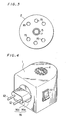
- Figs. 4 to 6 show a second embodiment of the invention which is substantially the same as the embodiment of Figs. I and 2 except that it is usable for both the outlet with plug holes in horizontal arrangement and the outlet with plug holes in vertical arrangement.
- a rotatable member 16 having a pair of plug pieces 12, 12 opposed to each other with the center of rotation positioned therebetween is fitted in the rear side of the body 1 centrally thereof.
- the rotatable member 16 has at its base end a disc portion 16a formed with an annular groove 17 in its outer periphery.
- An annular ridge 18 on the body 1 is fitted in the groove to render the rotatable member 16 rotatable.
- the plug pieces 12 may be pins or blades, or three pins including a grounding pin are usable as desired.
- the annular ridge 18 on the body 1 has a cutout 19 over an angular range of 90 degrees.
- a protrusion 20 projecting from the bottom of the annular groove 17 in the rotatable member 16 is fitted in the cutout 19.
- the protrusion 20 is movable with the rotation of the rotatable member 16 through the cutout 19 over the angular range of from 0 to 90 degrees.
- the plug pieces 12, 12 are arranged vertically, whereas when the protrusion bears on the other end of the cutout portion, the plug pieces are arranged horizontally.
- the plug pieces 12, 12 can be positioned selectively in the horizontal or vertical arrangement as desired by rotating the rotatable member 16.
- outlets are available in two types, i.e., horizontal and vertical, with respect to the arrangement of plug holes.
- the device with the plug usable for the two types is suited especially for export.
- the rotatable member 16 has a seat portion 16b projecting outward from the central part of the disk portion 16a.
- the seat portion 16b has the plug pieces 12, 12 fixedly implanted therein.
- the seat portion 16b provides a space between the body 1 and the outlet, consequently between the body and a pillar or wall, preventing the vapor of chemical component from depositing on the pillar or wall when the vapor is released from the top outlet 4 of the body 1.
- the seat portion 16b may be dispensed with.
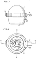
- Figs. 7 to 11 show a third embodiment of the invention which is substantially the same as the embodiment shown in Figs. 1 and 2 except that a skirt 21 is formed integrally with the lower end of the body 1.
- the solution bottle 8 attached to the socket 7 on the body 1 is surrounded by the skirt 21, which serves as a cover member for holding the solution bottle 8 out of sight and as a protective member for protecting the bottle 8 from impact or damage to be applied or caused thereto from outside.
- a circumferential clearance 22 formed between the solution bottle 8 and the skirt 21 is in communication with the interior of the body 1 through the intakes 15 in the bottom portion of the body 1, permitting outside air to flow into the body 1 smoothly.
- the upward current produced inside the body 1 diffuses the chemical with improved effectiveness on vaporization.
- Such an improvement in the diffusibility of the vaporized chemical can be achieved favorably especially by giving the vapor outlet 4 an overall opening area which is 2 to 40 times, preferably 5 to 15 times, the cross sectional area (thickness) of the wick 11 and making the total opening area of the air intakes 15 1.5 to 20 times, preferably 3 to 10 times, as large as the wick cross sectional area.
- the intake of outside air into the body 1 prevents the overheating of the bottle 8 and the rise of internal pressure thereof, thus serving to prevent leakage from the solution bottle 8.
- the intake 15 may be formed in a side portion of the body 1.
- the skirt 21 can be formed at the upper end of its rear side with a projection 23 projecting outward so as to be flush with the rear face of the plug block 12a at the block lower end.
- the projection 23 bears against the outlet face under the lower end of the plug block 12a to support the product against gravity by bearing contact with the outlet. This serves to lessen the gravitational load on the outlet-inserted portions of the plug, permitting the product to be held attached to the outlet with improved stability.
- the solution bottle 8 can be conveniently replaced with the skirt 21 removed.
- the skirt 21 is given the largest possible inside diameter, solution bottles 8 ranging from small to large sizes are usable free of trouble.
- the vaporizer can be packaged or stored in a compacted state, hence convenient.
- Fig. 12 shows a preferred example of chemical solution bottle 8 wherein a balance hole 25 is formed in its cap.
- a balance hole 25 When the internal temperature of the bottle 8 rises to raise the internal pressure during use for thermal vaporization, the balance hole 25 releases the pressure to the outside, thus serving to automatically maintain the internal pressure of the bottle 8 in balance with the external pressure. The pressure balance thus ensured completely eliminates the likelihood that the solution will spill out from the bottle 8 through the wick 11.
- the balance hole 25 may be preformed, or the bottle cap may have a thin wall portion for forming the balance hole 25 therein when the vaporizer is to be used.
- the balance hole 25, when preformed, may be closed with a seal before use.
- the solution bottle 8 which is left exposed at its lower portion, has the advantages that the bottle can be prevented from being overheated by the heater and permits the user to recognize the amount of remaining chemical solution like those of Figs. 1 to 6.
- the heater 5 may be suspended by a support (not shown) from the cover portion 3 of the body 1 centrally thereof.
- the cordless thermal vaporizer of the liquid type embodying the invention is so constructed that the body 1 thereof is attachable to the solution bottle with its socket 7 fitted thereto like a cap.
- the body 1 is therefore smaller and more lightweight than box-shaped bodies. Accordingly, the vaporizer can be used as attached to the outlet reliably with good stability, with a reduced gravitational load on the outlet-inserted plug portions. Further because the solution bottle 8 can be attached to the socket 7 of the body 1 as directly fitted thereto, the bottle 8 is easy to attach to and remove from the body 1.
- the present invention provides a cordless thermal vaporizer of the liquid type which is usable as attached to an outlet with good stability, along with a chemical solution bottle which is easy to replace.
- Chemical solutions for use in the invention were prepared by mixing together specified proportions of the insecticide AC, AO, AP or AQ, organic solvent and, when required, the comound CA, CB or CQ as listed in Table 1.
- the insecticides listed in Table 1 have the following vapor pressure.
- a comparative chemical solution was prepared using 12 wt.% of Phthalthrin (product of Sumitomo Chemical Co., Ltd.) having a vapor pressure of 3.5 x 10 -8 mm Hg/20°C and serving as an insecticide and 88 wt.% of BD serving as a solvent.
- Phthalthrin product of Sumitomo Chemical Co., Ltd.
- BD stands for 1,3,4,5,6,7-hexahydro-1,3-dioxo-2-isoindolyl methyl-dl-cis.trans chrysanthemate.
- a 7.5 ml quantity of each of the chemical solutions prepared in Examples 1 to 4 and the comparative solution obtained in Comparative Example 1 was placed into the bottle 8 shown in Fig. 2.
- the heater 5 was energized to heat the upper portion of the wick 11 from therearound to a temperature of 115°C and thereby test the solution for the vaporization of the insecticide in the solution.
- the wick 11 was prepared by admixing 20 parts by weight of starch and water with 60 parts by weight of perlite and 20 parts by weight of wood flour, kneading the mixture and extruding the mixture, followed by drying (6 mm in diameter and 70 mm in length, about 14 hours in oil absorption speed).
- the heater 5 used was in the form of a disk having an inside diameter of 10 mm and a thickness of 10 mm.
- the amount of vaporized insecticide was determined by trapping the vapor in a silica gel column by aspiration every hour, subjecting the silica gel to extraction with chloroform and quantitatively analyzing the extract by gas chromatography after concentration.
- Table 2 shows the results obtained by determining the amount of vaporization of the insecticide (mg) per hour, 10 hours, 100 hours, 200 hours, 300 hours and 720 hours after the start of heating of the sample.
- Table 2 reveals that the use of the chemical solution of the invention makes it possible to vaporize the insecticide at a remarkably improved rate and that the improved rate can be sustained even 720 hours after the start of heating almost without a substantial reduction.
- the chemical solution of the invention for use with the thermal vaporizer permits the use of a solution bottle of greatly reduced size, while the cordless device can be attached to the outlet reliably with good stability. Further the chemical solution itself is usable for at least 720 hours without clogging the wick, consequently assuring thermal vaporization for a prolonged period of time.
Abstract
Description
- The present invention relates to devices for thermal vaporization, and more particularly to thermal vaporizers of the so-called cordless type for use as directly attached to electric outlets provided on interior vertical surfaces as of walls, pillars, etc.
- Thermal vaporizers, such as electric mosquito controlling devices, include those of the mat type wherein a mat impregnated with an insecticidal solution is used as placed on a heat plate, and those of the liquid type wherein a chemical solution is heated for vaporization while being drawn up through a wick from a bottle. Those of the mat type include cordless devices already proposed, while cordless devices of the liquid type have yet to be proposed. The electric mosquito controlling device of the liquid type is relatively heavy in its entirety since the overall weight of the device includes the weight of the device body and that of the solution bottle. If cordless, the entire device must be supported against gravity solely by a plug attached to the electric outlet. It is therefore likely that the plug will slip off the outlet when the device is heavy. This defect has been a serious obstacle to overcome in designing cordless liquid-type devices. For example, the conventional electric mosquito controlling device of the liquid type with a cord comprises a box-shaped body and is used with a solution bottle accommodated in the body. The device body of the conventional structure must have a height at least sufficient for the body to accommodate the solution bottle and the wick projecting upward from the bottle, and is consequently large-sized, heavy and unsuited for use as a cordless device. The device is further inconvenient in that the bottom portion of the device body needs to be removed when the solution bottle is to be accommodated in the body.
- The main object of the present invention is to provide a cordless thermal vaporizer of the liquid type which is usable as attached to an electric outlet reliably with stability.
- Another object of the invention is to provide a cordless thermal vaporizer of the liquid type wherein a chemical solution bottle can be attached to the body of the device easily.
- Still another object of the invention is to provide a thermally vaporizable chemical solution which is usable for a prolonged period of time for thermal vaporization and can therefore be used as contained in a small bottle.
- Other features of the present invention will become apparent from the following description.
- The present invention provides a cordless thermal vaporizer for use with a plug inserted in an electric outlet, the vaporizer being characterized in that the body of the vaporizer is internally provided with a heater for heating a wick for drawing up a chemical solution from a bottle, and a socket disposed under the heater and removably fittable in the form of a cap to the bottle for attachment thereto.
- The thermal'vaporizer of the present invention is so constructed that the body thereof can be fittingly attached, at its socket in the form of a cap, to the chemical solution bottle. Accordingly, the body is smaller in size, especially in the dimension along the direction of its height, and in weight than the box-shaped conventional one. The reduced weight lessens the burden on the plug blades inserted in the outlet during use, almost completely eliminating the tendency for the plug to slip off the outlet and making the vaporizer usable as attached to the outlet reliably with stability.
- Since the solution bottle can be attached directly to the socket of the vaporizer body, the bottle is easy to fit in and remove.
- According to the present invention, the plug is provided on the rear side of the vaporizer body. Electric outlets are divided into two types: the vertical type for use with (two or three) plug blades as arranged vertically, and the horizontal type for use with plug blades as arranged horizontally. Either the vertical type or the horizontal type is used in countries depending on the domestic situation. When the plug is rotatable through an angular range of 0 to 90 degrees relative to the rear side of the body to make the arrangement of the plug blades selectively changeable to the vertical or horizontal direction, the vaporizer is usable for either one of the two types of outlets, hence convenient.
- According to the present invention, the vaporizer body can be provided at its lower end with a skirt for forming a circumferential clearance around the outer periphery of the solution bottle. The skirt functions as a protective member for protecting the solution bottle from external impact and further as a cover member for holding the bottle out of sight. Further when the clearance is made to communicate with the interior of the body, an air current flows upward through the clearance into the body, permitting a vapor of chemical to be entrained in the upward air current, whereby the chemical vapor can be diffused effectively.
- The thermally vaporizable chemical solution to be used as contained in the solution bottle according to the invention is a solution of at least one of chemicals such as insecticides, bactericides, repellents, miticides plant growth regulating agents, rodenticides, cosmetics, medicinals, perfumes, deodorants, herbicides, fungicides, insect repellents for clothes, mold inhibitors, etc. When required, variatous additives such as synergists and antioxidants are added to the solution.
- Preferably, these chemicals have a high vapor pressure of at least 3.5 x 10⁻⁸ mm Hg/20°C. Examples of such chemicals are given below.
-
- * (S)-2-Methyl-4-oxo-3-(2-propynyl)cyclopent-2-enyl(lR) -cis·trans-chrysanthemate (common name: Prallethrin, brand name: Etoc, product of Sumitomo Chemical Co., Ltd., hereinafter referred to as "AC")
- * l-Ethynyl-2-methyl-2-pentenyl cis-trans- chrysanthemate (hereinafter referred to as "AO")
- * l-Ethynyl-2-methyl-2-
pentenyl 2,2-dimethyl-3-(2-methyl-1-propenyl)cyclopropane-1-carboxylate (hereinafter referred to as "AP") - * l-Ethynyl-2-methyl-2-
pentenyl - * l-Ethynyl-2-methyl-2-
pentenyl 2,2-dimethyl-3-(2,2-dichlorovinyl)cyclopropane-l-carboxylate (hereinafter referred to as "AR") - * 2-Methyl-4-oxo-3-(2-propynyl)cyclopent-2-enyl- chrysanthemate (hereinafter referred to as "AS")
- * 0,0-Dimethyl 0-(2,2-dichloro)vinyl phosphate (hereinafter referred to as "AT")
- * o-Isopropoxyphenyl methylcarbamate (hereinafter referred to as "AU")
- Lauryl methacrylate, geranyl crotonate, citronella oil and lemon grass oil
-
- p-Chloro-m-xylenol (PCMX) and thiabendazole (TBZ) Rodent repellents
- N,N-Diethyl-m-toluamide (Deet) and dimethyl phthalate Insect repellents for clothes
- Empenthrin, naphthalene and p-dichlorobenzene
- Suitable solvents for dissolving the chemical are those having a boiling point of up to 350°C. Examples of such solvents are water, Deet, alcohol, silicone, aliphatic hydrocarbons, etc. Especially suitable aliphatic hydrocarbons are those having a boiling point of 150 to 350°C.
- The concentration of the chemical solution is about 1 to about 80 wt.%, preferably about 6 to about 75 wt.%, more preferably about 15 to about 50 wt.%.
- It is desirable to prepare the chemical solution from a chemical having a high vapor pressure and a solvent having a boiling point of up to 350°C (a boiling point of 150 to 350°C in the case of aliphatic hydrocarbons). The chemical solution is then usable in a small amount of about 7.5 ml for thermal vaporization for a long period of time of at least 720 hours. Accordingly, the solution bottle to be used can be small, with the result that the thermal vaporizer can be attached to the outlet more reliably with higher stability.
- The wick to be provided on the solution bottle may be made of any of various materials commonly used, such as felt, cotton, pulp, nonwoven fabric, asbestos, inorganic molding, etc. Preferred wicks are those made of felt, biscuit, pulp and inorganic molding. Examples of molded inorganic wicks are those prepared from porcelain porous material, glass fiber, asbestos or like inorganic fiber in the form of solid pieces with use of a binder such as gypsum, bentonite or the like, or those prepared from a mineral powder such as kaolin, activated clay, talc, kieselguhr, clay, perlite, bentonite, alumina, silica, alumina silica, titanium, fired vitreous voltanic rock powder, fired vitreous volcanic ash powder or the like, as used singly or in combination with wood flour, carbon powder, activated carbon or the like, in the form of solid pieces, using a glue such as dextrin, starch, gum arabic, synthetic glue, carboxymethyl cellulose or the like. More preferably, the wick is prepared from 100 parts by weight of such a mineral powder and 10 to 300 parts by weight of wood flour or a mixture of wood flour and carbon powder and/or activated carbon in an amount equal to that of wood flour in weight, by admixing with the resulting
mixture 5 to 25 wt.% of a glue based on the wick to be obtained, kneading the mixture with addition of water, extruding the mixture and drying the extrudate. It is desired that the wick be 1 to 40 hours, more desirably 8 to 21 hours, in oil absorption speed. The term "oil absorption speed" means a value determined by immersing the wick, as dimensioned to 7 mm in diameter and 70 mm in length, in liquid n-paraffin at 25°C over a length of 15 mm from its lower end and measuring the time required for the n-paraffin to reach the top of the wick. The wick may have incorporated therein pigments such as Malachite Green, fungicides such as sorbic acid, salts thereof and dehydroacetic acid, etc. in addition to the mineral powder, wood flour and glue. - The heater to be used in the vaporizer is generally an electric heater which produces heat when energized, whereas the heater is not limited to the electric one but can be any known heater including, for example, a material which produces heat on oxidation in air or a pyrogenic material utilizing platinum catalyst or the like.
- Various embodiments of the invention will be described below with reference to the accompanying drawings.
- Fig. 1 is a view in vertical section showing a first embodiment of the invention;
- Fig. 2 is a view in vertical section showing the first embodiment with a chemical solution bottle attached thereto;
- Fig. 3 is a bottom view showing a modification of the first embodiment;
- Fig. 4 is a perspective view showing a second embodiment of the invention;
- Fig. 5 is a view in vertical section of the same;
- Fig. 6 is a view illustrating an example of means for limiting the rotation of a rotatable member of the same;
- Fig. 7 is a side elevation showing a third embodiment of the invention;
- Fig. 8 is a bottom view of the same;
- Fig. 9 is a rear view of the same;
- Fig. 10 is a view in section taken along the line A-A in Fig. 8 and showing the same in use;
- Fig. 11 is a view in section taken along the line B-B in Fig. 8 and showing the same with a heater omitted; and
- Fig. 12 is a view in vertical section showing a preferred example of chemical solution bottle in use.
- Fig. 1 shows a first embodiment of the invention designed specifically for use with an outlet with blades in a horizontal arrangement. The embodiment has a
vaporizer body 1 comprising aflat bottom portion 2 and asemispherical cover portion 3. Avapor outlet 4 is formed in the center of the top of thecover portion 3. Aring heater 5 having an opening extending vertically therethrough is provided inside thebody 1 below thevapor outlet 4. Theheater 5 is supported at anouter flange 5a thereof by astay 6 on thebottom portion 2. Provided under theheater 5 is abottle socket 7 projecting upward from thebottom portion 2 and having an opening extending vertically therethrough. Thesocket 7 is formed on its inner periphery with a threadedportion 10 adapted for screw-thread engagement with a threadedportion 9 on the outer periphery of themouth 8a of a chemical solution bottle 8 (see Fig. 2). As seen in Fig. 2, thesolution bottle 8 is provided with awick 11 which is insertable into thering heater 5 concentrically therewith when thebottle 8 is attached at itsmouth 8a to thesocket 7. Plug blades 12 (two blades in a pair) in a horizontal arrangement are fixed to the lower end of thebody 1 on its rear side. Theplug blades 12 are connected to therespective terminals ring heater 5 with lead wires (not shown) in the usual manner. Aswitch 14 for turning on and off theheater 5 is provided at the lower end of thebody 1 on its front side. As seen in the bottom view of Fig. 3, air intakes 15 can be formed in thebottom portion 2 of the body. The air intakes 15 serve to diffuse the chemical on vaporization. - When the vaporizer is to be used, the
solution bottle 8 is attached at itsmouth 8a to thesocket 7 on thebody bottom portion 2 by the screw-thread engagement of the threadedportions wick 11 of thebottle 8 is inserted into thering heater 5 concentrically therewith. In this state, the heater is energized by inserting theplug blades 12 into an outlet (not shown), whereupon thering heater 5 produces heat to. heat the upper portion of thewick 11. A chemical solution can therefore be vaporized in the same manner as is the case with a device having a cord. - The vaporizer is used for insecticidal application by heating the
wick 11 at a suitable temperature at which the chemical solution in thebottle 8 can be vaporized from thewick 11. The heating temperature is not limited specifically but is suitably determined, for example, according to the kind of insecticidal or like solution. The surface temperature of the heat producing member is usually in the range of about 70 to about 150°C, preferably 110 to 145°C. In terms of the surface temperature of thewick 11, this range corresponds to about 60 to about 135°C, preferably about 95 to about 130°C. - Since the
solution bottle 8 can be attached at itsmouth 8a to thesocket 7 on thebody bottom portion 2, thebottle 8 is very easy to attach to and remove from thebody 1. Because thesocket 7 of thebody 1 is merely fitted in the form of a cap to themouth 8a of thesolution bottle 8, thebody 1 is diminished in size, especially in the dimension in the direction along its height. This results in a corresponding decrease in the weight of thebody 1, i.e., of the entire vaporizer, rendering the vaporizer attachable to the outlet with stability. Thesolution bottle 8, which is left exposed, can be prevented from being overheated by the heater and has the advantage that the amount of remaining solution can be readily checked through the bottle. - Although the screw-thread engagement between the threaded
portions solution bottle 8 to thesocket 7, the threadedportions solution bottle 8 may be sized as desired insofar as the vaporizer can be attached to the outlet free of trouble. - When the thermal vaporizer of the present invention is to be used as attached to a double outlet, it is likely that the body 1 (including the bottle 8) attached to one of the outlets will cover the other outlet to make the other outlet unusable depending on the size of the
body 1. Accordingly, it is desired that the dimensions of the vaporizer above and below theplug blades 12 be smaller than the spacing between the upper and lower outlets. For example, when the distance between the adjacent inner ends of the two outlets is 25 mm, the distances Dl and D2 shown in Fig. 2 are made not greater than 25 mm. - Figs. 4 to 6 show a second embodiment of the invention which is substantially the same as the embodiment of Figs. I and 2 except that it is usable for both the outlet with plug holes in horizontal arrangement and the outlet with plug holes in vertical arrangement.
- With this embodiment, a
rotatable member 16 having a pair ofplug pieces body 1 centrally thereof. Therotatable member 16 has at its base end adisc portion 16a formed with anannular groove 17 in its outer periphery. Anannular ridge 18 on thebody 1 is fitted in the groove to render therotatable member 16 rotatable. Theplug pieces 12 may be pins or blades, or three pins including a grounding pin are usable as desired. - With reference to Fig. 6, the
annular ridge 18 on thebody 1 has acutout 19 over an angular range of 90 degrees. Aprotrusion 20 projecting from the bottom of theannular groove 17 in therotatable member 16 is fitted in thecutout 19. As indicated by arrows in Fig. 6, theprotrusion 20 is movable with the rotation of therotatable member 16 through thecutout 19 over the angular range of from 0 to 90 degrees. For example when theprotrusion 20 bears on one end of thecutout portion 19 as shown in Fig. 6, theplug pieces - According to the present embodiment, the
plug pieces rotatable member 16. In foreign countries, outlets are available in two types, i.e., horizontal and vertical, with respect to the arrangement of plug holes. The device with the plug usable for the two types is suited especially for export. - The
rotatable member 16 has aseat portion 16b projecting outward from the central part of thedisk portion 16a. Theseat portion 16b has theplug pieces plug pieces seat portion 16b provides a space between thebody 1 and the outlet, consequently between the body and a pillar or wall, preventing the vapor of chemical component from depositing on the pillar or wall when the vapor is released from thetop outlet 4 of thebody 1. Theseat portion 16b may be dispensed with. - Figs. 7 to 11 show a third embodiment of the invention which is substantially the same as the embodiment shown in Figs. 1 and 2 except that a
skirt 21 is formed integrally with the lower end of thebody 1. - As will be apparent from the sectional view of Fig. 10 showing the embodiment in use, the
solution bottle 8 attached to thesocket 7 on thebody 1 is surrounded by theskirt 21, which serves as a cover member for holding thesolution bottle 8 out of sight and as a protective member for protecting thebottle 8 from impact or damage to be applied or caused thereto from outside. These two functions give an attractive appearance to the product and make it usable with safety. - A
circumferential clearance 22 formed between thesolution bottle 8 and theskirt 21 is in communication with the interior of thebody 1 through theintakes 15 in the bottom portion of thebody 1, permitting outside air to flow into thebody 1 smoothly. The upward current produced inside thebody 1 diffuses the chemical with improved effectiveness on vaporization. Such an improvement in the diffusibility of the vaporized chemical can be achieved favorably especially by giving thevapor outlet 4 an overall opening area which is 2 to 40 times, preferably 5 to 15 times, the cross sectional area (thickness) of thewick 11 and making the total opening area of the air intakes 15 1.5 to 20 times, preferably 3 to 10 times, as large as the wick cross sectional area. The intake of outside air into thebody 1 prevents the overheating of thebottle 8 and the rise of internal pressure thereof, thus serving to prevent leakage from thesolution bottle 8. Theintake 15 may be formed in a side portion of thebody 1. - According to the present embodiment, the
skirt 21 can be formed at the upper end of its rear side with aprojection 23 projecting outward so as to be flush with the rear face of theplug block 12a at the block lower end. When the plug is attached to the outlet, theprojection 23 bears against the outlet face under the lower end of theplug block 12a to support the product against gravity by bearing contact with the outlet. This serves to lessen the gravitational load on the outlet-inserted portions of the plug, permitting the product to be held attached to the outlet with improved stability. - When the
skirt 21 is made suitably detachable from thebody 1 at a projection-indentationfitting portion 24, thesolution bottle 8 can be conveniently replaced with theskirt 21 removed. When theskirt 21 is given the largest possible inside diameter,solution bottles 8 ranging from small to large sizes are usable free of trouble. - When the
plug block 12a is rotatable or slidable with theplug pieces 12 made retractable into thebody 1 suitably, the vaporizer can be packaged or stored in a compacted state, hence convenient. - Fig. 12 shows a preferred example of
chemical solution bottle 8 wherein abalance hole 25 is formed in its cap. When the internal temperature of thebottle 8 rises to raise the internal pressure during use for thermal vaporization, thebalance hole 25 releases the pressure to the outside, thus serving to automatically maintain the internal pressure of thebottle 8 in balance with the external pressure. The pressure balance thus ensured completely eliminates the likelihood that the solution will spill out from thebottle 8 through thewick 11. Thebalance hole 25 may be preformed, or the bottle cap may have a thin wall portion for forming thebalance hole 25 therein when the vaporizer is to be used. Thebalance hole 25, when preformed, may be closed with a seal before use. - The
solution bottle 8, which is left exposed at its lower portion, has the advantages that the bottle can be prevented from being overheated by the heater and permits the user to recognize the amount of remaining chemical solution like those of Figs. 1 to 6. - According to the invention, the
heater 5 may be suspended by a support (not shown) from thecover portion 3 of thebody 1 centrally thereof. - The cordless thermal vaporizer of the liquid type embodying the invention is so constructed that the
body 1 thereof is attachable to the solution bottle with itssocket 7 fitted thereto like a cap. Thebody 1 is therefore smaller and more lightweight than box-shaped bodies. Accordingly, the vaporizer can be used as attached to the outlet reliably with good stability, with a reduced gravitational load on the outlet-inserted plug portions. Further because thesolution bottle 8 can be attached to thesocket 7 of thebody 1 as directly fitted thereto, thebottle 8 is easy to attach to and remove from thebody 1. - Thus, the present invention provides a cordless thermal vaporizer of the liquid type which is usable as attached to an outlet with good stability, along with a chemical solution bottle which is easy to replace.
- Chemical solutions useful for the thermal vaporizer of the invention will be described below in greater detail.
- Chemical solutions for use in the invention were prepared by mixing together specified proportions of the insecticide AC, AO, AP or AQ, organic solvent and, when required, the comound CA, CB or CQ as listed in Table 1.

- The symbols used for the solvents given in Table 1 represent the following.
- BA: aliphatic hydrocarbon boiling at 150-180°C/760 mm Hg.
- BB: aliphatic hydrocarbon boiling at 180-210°C/760 mm Hg.
- BC: aliphatic hydrocarbon boiling at 210-240°C/760 mm Hg.
- BD: aliphatic hydrocarbon boiling at 240-270°C/760 mm Hg.
- BE: aliphatic hydrocarbon boiling at 270-300°C/760 mm Hg.
- BF: aliphatic hydrocarbon boiling at 300-350°C/760 mm Hg.
- The insecticides listed in Table 1 have the following vapor pressure.


- A comparative chemical solution was prepared using 12 wt.% of Phthalthrin (product of Sumitomo Chemical Co., Ltd.) having a vapor pressure of 3.5 x 10⁻⁸ mm Hg/20°C and serving as an insecticide and 88 wt.% of BD serving as a solvent. BD stands for 1,3,4,5,6,7-hexahydro-1,3-dioxo-2-isoindolyl methyl-dl-cis.trans chrysanthemate.
- A 7.5 ml quantity of each of the chemical solutions prepared in Examples 1 to 4 and the comparative solution obtained in Comparative Example 1 was placed into the
bottle 8 shown in Fig. 2. Theheater 5 was energized to heat the upper portion of thewick 11 from therearound to a temperature of 115°C and thereby test the solution for the vaporization of the insecticide in the solution. Thewick 11 was prepared by admixing 20 parts by weight of starch and water with 60 parts by weight of perlite and 20 parts by weight of wood flour, kneading the mixture and extruding the mixture, followed by drying (6 mm in diameter and 70 mm in length, about 14 hours in oil absorption speed). Theheater 5 used was in the form of a disk having an inside diameter of 10 mm and a thickness of 10 mm. - The amount of vaporized insecticide was determined by trapping the vapor in a silica gel column by aspiration every hour, subjecting the silica gel to extraction with chloroform and quantitatively analyzing the extract by gas chromatography after concentration.
- Table 2 shows the results obtained by determining the amount of vaporization of the insecticide (mg) per hour, 10 hours, 100 hours, 200 hours, 300 hours and 720 hours after the start of heating of the sample.

- Table 2 reveals that the use of the chemical solution of the invention makes it possible to vaporize the insecticide at a remarkably improved rate and that the improved rate can be sustained even 720 hours after the start of heating almost without a substantial reduction.
- The chemical solution of the invention for use with the thermal vaporizer permits the use of a solution bottle of greatly reduced size, while the cordless device can be attached to the outlet reliably with good stability. Further the chemical solution itself is usable for at least 720 hours without clogging the wick, consequently assuring thermal vaporization for a prolonged period of time.
Claims (5)
Applications Claiming Priority (9)
| Application Number | Priority Date | Filing Date | Title |
|---|---|---|---|
| JP1653388 | 1988-02-10 | ||
| JP16533/88U | 1988-02-10 | ||
| JP72878/88U | 1988-06-01 | ||
| JP7287888 | 1988-06-01 | ||
| JP11037188 | 1988-08-23 | ||
| JP110371/88U | 1988-08-23 | ||
| JP1988150437U JPH0718294Y2 (en) | 1988-02-10 | 1988-11-17 | Heating evaporator |
| JP150437/88U | 1988-11-17 | ||
| PCT/JP1989/000126 WO1989007394A1 (en) | 1988-02-10 | 1989-02-08 | Heater-fumigator |
Publications (3)
| Publication Number | Publication Date |
|---|---|
| EP0362397A1 true EP0362397A1 (en) | 1990-04-11 |
| EP0362397A4 EP0362397A4 (en) | 1990-06-27 |
| EP0362397B1 EP0362397B1 (en) | 1994-07-27 |
Family
ID=27456593
Family Applications (1)
| Application Number | Title | Priority Date | Filing Date |
|---|---|---|---|
| EP89902287A Expired - Lifetime EP0362397B1 (en) | 1988-02-10 | 1989-02-08 | Heater-fumigator |
Country Status (10)
| Country | Link |
|---|---|
| US (1) | US5038394A (en) |
| EP (1) | EP0362397B1 (en) |
| JP (1) | JPH0718294Y2 (en) |
| KR (1) | KR960004697B1 (en) |
| AT (1) | ATE108977T1 (en) |
| DE (1) | DE68917068T2 (en) |
| ES (1) | ES2013396A6 (en) |
| OA (1) | OA09084A (en) |
| PT (1) | PT89680B (en) |
| WO (1) | WO1989007394A1 (en) |
Cited By (20)
| Publication number | Priority date | Publication date | Assignee | Title |
|---|---|---|---|---|
| EP0334785A2 (en) * | 1988-03-04 | 1989-09-27 | Cooper-Zeltia, S.A. | Device for vaporizing thermically vaporizable substances |
| EP0420144A1 (en) * | 1989-09-29 | 1991-04-03 | ZOBELE INDUSTRIE CHIMICHE S.p.A. | Apparatus to keep flying insects, particularly mosquitoes, away from people |
| EP0689766A1 (en) * | 1994-06-28 | 1996-01-03 | FALP S.r.l. | Apparatus for vaporizing insecticidal solutions and the like |
| EP0696457A1 (en) * | 1994-08-03 | 1996-02-14 | Steinel GmbH & Co. KG | Electric vaporizer for active substances |
| EP0736248A1 (en) * | 1995-04-06 | 1996-10-09 | FALP S.r.l. | Apparatus for vaporizing insecticidal solutions and the like |
| EP0828271A1 (en) * | 1996-09-04 | 1998-03-11 | Steinel GmbH & Co. KG | Electrical vaporizer for active substances |
| WO1998058692A1 (en) * | 1997-06-24 | 1998-12-30 | Dbk España S.A. | Evaporator device of volatile products with variable evaporation intensity |
| EP1195169A1 (en) * | 2000-10-09 | 2002-04-10 | C.T.R., Consultoria, Técnica e Representaçoes Lda | Vaporisation device for volatile compounds, in particular for insecticides or perfumes |
| US6501906B2 (en) | 2000-12-18 | 2002-12-31 | C.T.R. Consultoria Tecnica E Representacoes Lda | Evaporation device for volatile substances |
| CN1108827C (en) * | 1994-08-03 | 2003-05-21 | 思泰诺尔两合有限公司 | Electric evaporator for added materials |
| WO2003103387A2 (en) * | 2002-06-06 | 2003-12-18 | S.C. Johnson & Son, Inc. | Localized surface volatilization |
| US7014818B2 (en) | 2000-03-06 | 2006-03-21 | Reckitt Benckiser (Uk) Limited | Electrical device for evaporating volatile liquid |
| US7167641B2 (en) | 2002-06-06 | 2007-01-23 | S.C. Johnson & Son, Inc. | Localized surface volatilization |
| USRE40392E1 (en) | 1999-02-25 | 2008-06-24 | Reckitt Benckiser (Uk) Limited | Electric evaporator device |
| USRE40464E1 (en) | 2001-04-05 | 2008-08-26 | C.T.R. | Evaporation device for multiple volatile substances |
| WO2013043819A3 (en) * | 2011-09-22 | 2013-06-06 | S. C. Jonhson & Son, Inc. | Rotatable plug assembly and housing for a volatile material dispenser |
| US8632059B2 (en) | 2001-10-04 | 2014-01-21 | Ctr Consultoria Tecnica E Representacoes, Lda | Dispersing fragrances |
| US8858236B2 (en) | 2011-10-28 | 2014-10-14 | S.C. Johnson & Son, Inc. | Rotatable plug assembly and method of reducing strain in a wire |
| EP3282812A1 (en) | 2016-08-09 | 2018-02-14 | Henkel AG & Co. KGaA | Heating element for a volatile liquid emanation device |
| EP3282813A1 (en) | 2016-08-09 | 2018-02-14 | Henkel AG & Co. KGaA | Device for emanating materials |
Families Citing this family (100)
| Publication number | Priority date | Publication date | Assignee | Title |
|---|---|---|---|---|
| US5222186A (en) * | 1991-12-06 | 1993-06-22 | Globol Gmbh | Electrical apparatus for vaporizing of active substances |
| GB2308244B (en) * | 1992-09-02 | 1997-08-20 | Otter Controls Ltd | Improvements relating to electrical appliances and connectors therefor |
| JPH08502398A (en) * | 1992-09-02 | 1996-03-12 | オッター・コントロールズ・リミテッド | Charging unit for cordless equipment |
| CN2166101Y (en) * | 1993-04-20 | 1994-05-25 | 卜冠华 | Gas generator for perfume solvent |
| US5591395A (en) * | 1995-08-03 | 1997-01-07 | S. C. Johnson & Son, Inc. | Method of disinfecting air |
| US5647053A (en) * | 1995-10-11 | 1997-07-08 | S. C. Johnson & Son, Inc. | Vapor dipensing device |
| US5903710A (en) * | 1997-04-14 | 1999-05-11 | S. C. Johnson & Son, Inc. | Air freshener dispenser device with disposable heat-promoted cartridge |
| US5945094A (en) * | 1997-04-14 | 1999-08-31 | S. C. Johnson & Son, Inc. | Disposable plug-in dispenser for use with air freshener and the like |
| US6123935A (en) * | 1997-04-14 | 2000-09-26 | S. C. Johnson & Son, Inc. | Air freshener dispenser device with disposable heat-activated cartridge |
| US5976503A (en) * | 1997-04-14 | 1999-11-02 | S. C. Johnson & Son, Inc. | Disposable plug-in air freshener with heat activated cartridge |
| ES2163956B2 (en) * | 1998-08-21 | 2003-05-01 | Dbk Espana Sa | EVAPORATOR DEVICE OF VOLATILE PRODUCTS WITH VARIABLE EVAPORATION INTENSITY, BY THE INTERPOSITION OF A MOBILE CAP. |
| US6361752B1 (en) * | 1999-05-19 | 2002-03-26 | S. C. Johnson & Son, Inc. | Apparatus for volatilizing and dispensing a chemical into a room environment |
| US6104867A (en) * | 1999-06-16 | 2000-08-15 | The Dial Corporation | Method and apparatus for liquid vaporization |
| WO2000076292A2 (en) | 1999-06-16 | 2000-12-21 | The Dial Corporation | Liquid vaporization with housing stabilization system |
| GB2354445B (en) | 1999-09-24 | 2001-11-21 | Reckitt Benckiser | Device |
| ES1044854Y (en) * | 1999-11-04 | 2000-11-16 | Vidal Maria Jose Arias | ELECTRIC AIR FRESHENER FOR CAR. |
| US6236807B1 (en) * | 2000-01-07 | 2001-05-22 | Bath & Body Works, Inc. | Wick-based liquid emanation system with child-resistant and miniaturization features |
| US6661967B2 (en) | 2000-02-25 | 2003-12-09 | The Dial Corporation | Variable temperature vaporizer |
| US6792199B2 (en) * | 2000-02-25 | 2004-09-14 | The Dial Corporation | Variable temperature vaporizer |
| US6315821B1 (en) | 2000-05-03 | 2001-11-13 | Hamilton Beach/Proctor-Silex, Inc. | Air filtration device including filter change indicator |
| US6328791B1 (en) | 2000-05-03 | 2001-12-11 | Hamilton Beach/Proctor-Silex, Inc. | Air filtration device |
| US8061628B1 (en) | 2000-07-27 | 2011-11-22 | The Procter & Gamble Company | Systems and devices for emitting volatile compositions |
| US20040033171A1 (en) * | 2000-07-27 | 2004-02-19 | The Procter & Gamble Company | Systems and devices for emitting volatile compositions |
| US20040265164A1 (en) * | 2000-07-27 | 2004-12-30 | The Procter & Gamble Company | Methods, devices, compositions, and systems for improved scent delivery |
| US6931202B2 (en) | 2000-07-28 | 2005-08-16 | S.C. Johnson & Son, Inc. | Electrical evaporator with adjustable evaporation intensity |
| IT1318278B1 (en) * | 2000-07-28 | 2003-07-28 | Zobele Ind Chimiche S P A Ora | ELECTRIC VAPORIZER OF INSECTICIDES OR PERFUMES IN LIQUID FORMULATIONS, WITH ADJUSTABLE EVAPORATION INTENSITY. |
| US6446880B1 (en) * | 2000-08-02 | 2002-09-10 | S.C. Johnson & Son, Inc. | Replaceable reservoir for an atomizing apparatus |
| AU2001293097A1 (en) * | 2000-09-26 | 2002-04-08 | S. C. Johnson And Son, Inc. | Modular electrical device for delivery of volatile compounds |
| MXPA03002906A (en) * | 2000-10-03 | 2003-06-24 | Dbk Espana Sa | Heater device for active substances. |
| ES2230196T3 (en) * | 2001-04-05 | 2005-05-01 | C.T.R., Consultoria, Tecnica E Representacoies Lda | DEVICE FOR VAPORZATION OF VOLATILE SUBSTANCES, ESPECIALLY INSECTICIDES AND / OR AROMATIC SUBSTANCES. |
| EP1249163A1 (en) * | 2001-04-09 | 2002-10-16 | Zelnova, S.A. | Thermal vaporizer for a liquid formulation comprising a volatile active |
| EP1258190A1 (en) | 2001-05-19 | 2002-11-20 | Givaudan SA | Unit for dispensing a volatile liquid |
| WO2003013619A1 (en) * | 2001-08-03 | 2003-02-20 | S.T. Chemical Co., Ltd. | Liquid-absorbing core |
| US6862403B2 (en) * | 2001-08-07 | 2005-03-01 | S.C. Johnson & Son, Inc. | Rotatable plug assembly including an extra outlet |
| EP1283062B1 (en) * | 2001-08-07 | 2006-05-03 | S.C. Johnson & Son, Inc. | Polyfunctional electric wall evaporator |
| CN1263518C (en) * | 2001-11-20 | 2006-07-12 | Dbk西班牙股份有限公司 | Method of disinfecting and scenting the air using essential oils |
| EP1483966A4 (en) * | 2002-02-07 | 2005-04-06 | Kuraray Co | Method of controlling acarian and device for use in the same |
| US7155116B2 (en) | 2002-08-16 | 2006-12-26 | The Dial Corporation | Methods and apparatus for a discrete vapor-dispensing device |
| US6885811B2 (en) * | 2002-08-16 | 2005-04-26 | The Dial Corporation | Methods and apparatus for dual-outlet vapor dispenser |
| US6697571B2 (en) | 2002-03-11 | 2004-02-24 | The Dial Corporation | Method and apparatus for selective positioning a wick material in a vapor-dispensing device |
| ITVE20020012A1 (en) * | 2002-03-13 | 2003-09-15 | Alper Srl | ELECTRIC DEANANT OR INSECTICIDE EMANATOR. |
| US6808684B2 (en) | 2002-04-05 | 2004-10-26 | International Flavors & Fragrance Inc. | Fragrance material |
| US6861031B2 (en) * | 2002-04-05 | 2005-03-01 | International Flavors & Fragrances Inc. | Fragrance material |
| US6659301B2 (en) | 2002-04-08 | 2003-12-09 | Waldwick Plastics Inc. | Liquid vaporization device and bottle |
| EP1512312A4 (en) | 2002-05-13 | 2006-11-22 | Johnson & Son Inc S C | Coordinated emission of fragrance, light, and sound |
| AU2003229188A1 (en) * | 2002-05-17 | 2003-12-02 | Greenlight Power Technologies, Inc. | System and method for converting a liquid into a vapor |
| US6622662B1 (en) * | 2002-06-12 | 2003-09-23 | The Dial Corporation | Adapter for vaporizing devices |
| US6619560B1 (en) | 2002-07-19 | 2003-09-16 | Blyth, Inc. | Bottle assembly with wick holder assembly |
| US20040033067A1 (en) * | 2002-08-16 | 2004-02-19 | He Mengtao Pete | Methods and apparatus for a controllable vapor-dispensing device |
| US6895177B2 (en) | 2002-08-16 | 2005-05-17 | The Dial Corporation | Vapor dispensing device having improved transverse loading stability |
| US7249719B2 (en) | 2002-08-30 | 2007-07-31 | The Dial Corporation | Method and apparatus for a multiple source vapor-dispensing device |
| US6897381B2 (en) | 2002-08-30 | 2005-05-24 | The Dial Corporation | Wall-mounted electrical device having adjustable outlet prongs |
| AU2003279705A1 (en) | 2002-08-30 | 2004-03-19 | The Dial Corporation | Vaporiser |
| EP1539257B1 (en) | 2002-08-30 | 2006-10-11 | The Dial Corporation | Methods and apparatus for a variable resistor configured to compensate for non-linearities in a heating element circuit |
| US7083162B2 (en) | 2002-08-30 | 2006-08-01 | The Dial Corporation | Intermediary device |
| WO2004035097A1 (en) * | 2002-10-15 | 2004-04-29 | Zobele España, S.A. | Method of disinfecting, freshening and scenting the air using essential oils and/or the active principles thereof |
| US7138130B2 (en) * | 2003-01-30 | 2006-11-21 | S.C. Johnson & Son, Inc. | Substrate for volatile delivery systems |
| AU2004212459B2 (en) | 2003-02-07 | 2010-03-11 | S.C. Johnson & Son, Inc. | Diffuser with light emitting diode nightlight |
| US20040170404A1 (en) * | 2003-02-27 | 2004-09-02 | Kenney Nicholas B | Plug-in pet deterrent |
| US20040195245A1 (en) * | 2003-03-21 | 2004-10-07 | Kishen Gohil | Top mounting for a container for a volatile liquid dispenser |
| CN100381083C (en) | 2003-04-29 | 2008-04-16 | 韩力 | Electronic nonflammable spraying cigarette |
| US6859615B2 (en) * | 2003-05-01 | 2005-02-22 | Hometek International Ltd. | Multi-fragrance scent dispenser |
| US6871794B2 (en) | 2003-05-01 | 2005-03-29 | E. I. Du Pont De Nemours And Company | Liquid dispersion device |
| US8301019B2 (en) * | 2003-09-04 | 2012-10-30 | Bath & Body Works Brand Management, Inc. | Fragrance emanation system |
| US7258868B2 (en) * | 2004-01-15 | 2007-08-21 | S.C. Johnson & Son, Inc. | Volatile releasing substrates and methods for preparing them |
| US6996335B2 (en) * | 2004-02-12 | 2006-02-07 | S.C. Johnson & Son, Inc. | Electrical evaporator with ratcheting wick adjuster |
| US20050255008A1 (en) * | 2004-04-20 | 2005-11-17 | Hao-Cheng Lin | Portable fragrance disperser |
| US7303143B2 (en) | 2004-06-24 | 2007-12-04 | S.C. Johnson & Son, Inc. | Wick assembly |
| US6968124B1 (en) | 2004-06-25 | 2005-11-22 | S. C. Johnson & Son, Inc. | Electric liquid volatile dispenser |
| US20060110144A1 (en) * | 2004-11-09 | 2006-05-25 | Fellows Robert T | Bottle for liquid vaporization device |
| CN2792961Y (en) * | 2005-03-25 | 2006-07-05 | 刘军伍 | Loading and unloading liquid-storing bottle |
| US7589340B2 (en) * | 2005-03-31 | 2009-09-15 | S.C. Johnson & Son, Inc. | System for detecting a container or contents of the container |
| US7281811B2 (en) | 2005-03-31 | 2007-10-16 | S. C. Johnson & Son, Inc. | Multi-clarity lenses |
| US7643734B2 (en) | 2005-03-31 | 2010-01-05 | S.C. Johnson & Son, Inc. | Bottle eject mechanism |
| DE602005016777D1 (en) * | 2005-04-19 | 2009-11-05 | Zobele Holding Spa | Plug and heater assembly of a volatile diffusion device |
| US7368003B2 (en) | 2005-06-24 | 2008-05-06 | S.C. Johnson & Son, Inc. | Systems for and methods of providing air purification in combination with odor elimination |
| US7537647B2 (en) | 2005-08-10 | 2009-05-26 | S.C. Johnson & Son, Inc. | Air purifier |
| US20070158456A1 (en) * | 2006-01-09 | 2007-07-12 | Donald Spector | Long Term Active Fragrancer |
| WO2007136795A1 (en) * | 2006-05-19 | 2007-11-29 | Porex Corporation | Vapor dispenser with indicator |
| US7544331B1 (en) | 2006-07-10 | 2009-06-09 | Romano Pettaway | Vehicle lighter air freshener |
| US7840123B2 (en) | 2007-06-21 | 2010-11-23 | S.C. Johnson & Son, Inc. | Diffusion device |
| US7798422B2 (en) * | 2007-07-19 | 2010-09-21 | Trevino Ruben E | Cedar oil evaporators |
| US20090101730A1 (en) * | 2007-10-19 | 2009-04-23 | Davis Brian T | Vented Dispensing Bottle/Cap Assembly |
| US8320751B2 (en) | 2007-12-20 | 2012-11-27 | S.C. Johnson & Son, Inc. | Volatile material diffuser and method of preventing undesirable mixing of volatile materials |
| US20090261179A1 (en) * | 2008-04-16 | 2009-10-22 | Ashland Licensing And Intellectual Property Llc | Bottle cap seal for wicked air freshener |
| WO2010014996A2 (en) * | 2008-08-01 | 2010-02-04 | Porex Corporation | Wicks for dispensers of vaporizable materials |
| EP2376683B1 (en) * | 2009-01-09 | 2014-06-11 | Porex Corporation | Hydrophilic porous wicks for vaporizable materials |
| HK1138474A2 (en) * | 2009-06-26 | 2010-08-20 | Shining Union Ltd | A relaxation system |
| USD639923S1 (en) | 2010-04-15 | 2011-06-14 | S.C. Johnson & Son, Inc. | Dispensing device |
| US9770524B2 (en) | 2010-07-16 | 2017-09-26 | S. C. Johnson & Son, Inc. | Volatile material dispenser and method of attaching a refill or refills to same |
| US9370594B2 (en) | 2010-07-16 | 2016-06-21 | S. C. Johnson & Son, Inc. | Volatile material dispenser and method of retaining only compatible refills thereby |
| USD732389S1 (en) | 2012-07-31 | 2015-06-23 | S.C. Johnson & Son, Inc. | Cap |
| US8983279B2 (en) | 2012-07-31 | 2015-03-17 | S.C. Johnson & Son, Inc. | Volatile material dispenser and method of emitting a volatile material |
| US9669126B2 (en) * | 2012-08-06 | 2017-06-06 | S.C. Johnson & Son, Inc. | Volatile material dispenser and method of emitting a volatile material |
| US10405580B2 (en) * | 2016-07-07 | 2019-09-10 | Altria Client Services Llc | Mechanically-adjustable e-vaping device flavor assembly |
| US11925732B2 (en) * | 2018-09-26 | 2024-03-12 | The Yankee Candle Company, Inc. | Device for volatilizing compounds with a selectively adjustable heat source |
| CN209965060U (en) * | 2019-03-28 | 2020-01-21 | 深圳市乐氛实业有限公司 | Mosquito dispeller with good mosquito killing effect |
| USD975263S1 (en) | 2020-04-20 | 2023-01-10 | Korri L. Wright | Electronic fragrance emitter |
| US20220104546A1 (en) * | 2020-10-05 | 2022-04-07 | Henkel IP & Holding GmbH | Vapor dispensing apparatus having a tubular wick section with an internal heating element and refills therefor |
| BE1030394B1 (en) | 2022-03-28 | 2023-10-24 | Oystershell Nv | DELIVERY DEVICE FOR VOLATILE SUBSTANCES |
Citations (5)
| Publication number | Priority date | Publication date | Assignee | Title |
|---|---|---|---|---|
| BE552525A (en) * | 1956-02-08 | |||
| JPS5845670U (en) * | 1981-09-21 | 1983-03-28 | ア−ス製薬株式会社 | container |
| FR2558730A1 (en) * | 1984-01-31 | 1985-08-02 | Earth Chemical Co | THERMO-SPRAYABLE PRODUCTS AND DEVICE FOR ITS VAPORIZATION |
| GB2192337A (en) * | 1986-07-12 | 1988-01-13 | Beecham Group Plc | Vapourising device |
| EP0253640A2 (en) * | 1986-07-18 | 1988-01-20 | Sumitomo Chemical Company, Limited | A method for killing insects by heating fumigation |
Family Cites Families (17)
| Publication number | Priority date | Publication date | Assignee | Title |
|---|---|---|---|---|
| GB672097A (en) * | ||||
| US1994932A (en) * | 1932-02-27 | 1935-03-19 | Vidal Pierre Lucien | System for vaporizing liquids and the absorption of smoke, evil odors, and the like |
| US2597195A (en) * | 1950-03-18 | 1952-05-20 | Garland D Runnels | Vaporizer |
| CH337992A (en) * | 1955-11-15 | 1959-04-30 | Armo Kunststoffe V Laemmler In | Evaporator |
| US2898649A (en) * | 1956-11-19 | 1959-08-11 | Elaine T Cassidy | Perfume diffuser |
| JPS4325081Y1 (en) * | 1964-09-14 | 1968-10-21 | ||
| JPS4326273Y1 (en) * | 1965-07-30 | 1968-11-01 | ||
| US3431393A (en) * | 1965-09-07 | 1969-03-04 | Dainippon Jochugiku Kk | Apparatus for vaporizing chemicals and perfumes by heating |
| US3780260A (en) * | 1972-08-04 | 1973-12-18 | E Elsner | Combination night light and liquid vaporizer |
| JPS5845670B2 (en) * | 1973-08-31 | 1983-10-12 | ナカノ ツネタロウ | Battery tester |
| JPS5940409B2 (en) * | 1978-10-27 | 1984-09-29 | ア−ス製薬株式会社 | liquid absorption core |
| JPS6310696Y2 (en) * | 1979-09-11 | 1988-03-30 | ||
| JPS5962784U (en) * | 1982-10-20 | 1984-04-25 | ア−ス製薬株式会社 | Heating evaporation device |
| JPS6169983U (en) * | 1984-10-12 | 1986-05-13 | ||
| JPS6245986U (en) * | 1985-09-06 | 1987-03-20 | ||
| US4804821A (en) * | 1986-06-24 | 1989-02-14 | Environmental Fragrance Technologies, Ltd. | Aroma diffuser assembly |
| JPH053020Y2 (en) * | 1986-11-19 | 1993-01-25 |
-
1988
- 1988-11-17 JP JP1988150437U patent/JPH0718294Y2/en not_active Expired - Lifetime
-
1989
- 1989-02-08 KR KR1019890701854A patent/KR960004697B1/en not_active IP Right Cessation
- 1989-02-08 DE DE68917068T patent/DE68917068T2/en not_active Expired - Lifetime
- 1989-02-08 AT AT89902287T patent/ATE108977T1/en not_active IP Right Cessation
- 1989-02-08 US US07/425,211 patent/US5038394A/en not_active Expired - Lifetime
- 1989-02-08 WO PCT/JP1989/000126 patent/WO1989007394A1/en active IP Right Grant
- 1989-02-08 EP EP89902287A patent/EP0362397B1/en not_active Expired - Lifetime
- 1989-02-10 PT PT89680A patent/PT89680B/en not_active IP Right Cessation
- 1989-02-10 ES ES8900807A patent/ES2013396A6/en not_active Expired - Lifetime
- 1989-10-10 OA OA59661A patent/OA09084A/en unknown
Patent Citations (5)
| Publication number | Priority date | Publication date | Assignee | Title |
|---|---|---|---|---|
| BE552525A (en) * | 1956-02-08 | |||
| JPS5845670U (en) * | 1981-09-21 | 1983-03-28 | ア−ス製薬株式会社 | container |
| FR2558730A1 (en) * | 1984-01-31 | 1985-08-02 | Earth Chemical Co | THERMO-SPRAYABLE PRODUCTS AND DEVICE FOR ITS VAPORIZATION |
| GB2192337A (en) * | 1986-07-12 | 1988-01-13 | Beecham Group Plc | Vapourising device |
| EP0253640A2 (en) * | 1986-07-18 | 1988-01-20 | Sumitomo Chemical Company, Limited | A method for killing insects by heating fumigation |
Non-Patent Citations (1)
| Title |
|---|
| See also references of WO8907394A1 * |
Cited By (37)
| Publication number | Priority date | Publication date | Assignee | Title |
|---|---|---|---|---|
| EP0334785A3 (en) * | 1988-03-04 | 1991-02-06 | Cooper-Zeltia, S.A. | Device for vaporizing thermically vaporizable substances |
| EP0334785A2 (en) * | 1988-03-04 | 1989-09-27 | Cooper-Zeltia, S.A. | Device for vaporizing thermically vaporizable substances |
| EP0420144A1 (en) * | 1989-09-29 | 1991-04-03 | ZOBELE INDUSTRIE CHIMICHE S.p.A. | Apparatus to keep flying insects, particularly mosquitoes, away from people |
| US5095647A (en) * | 1989-09-29 | 1992-03-17 | Zobele Industrie Chimiche S.P.A. | Apparatus to keep flying insects, particularly mosquitoes, away from people |
| EP0689766A1 (en) * | 1994-06-28 | 1996-01-03 | FALP S.r.l. | Apparatus for vaporizing insecticidal solutions and the like |
| US5926614A (en) * | 1994-08-03 | 1999-07-20 | Steinel Gmbh & Co. Kg | Electric device for the vaporization of additives |
| EP0696457A1 (en) * | 1994-08-03 | 1996-02-14 | Steinel GmbH & Co. KG | Electric vaporizer for active substances |
| WO1996004021A1 (en) * | 1994-08-03 | 1996-02-15 | Steinel Gmbh & Co. Kg | Electrical device for evaporating active substances |
| AU683402B2 (en) * | 1994-08-03 | 1997-11-06 | Steinel Gmbh & Co. Kg | Electrical device for evaporating active substances |
| CN1108828C (en) * | 1994-08-03 | 2003-05-21 | 思泰诺尔两合有限公司 | Electrical device for evaporating active substances |
| CN1108827C (en) * | 1994-08-03 | 2003-05-21 | 思泰诺尔两合有限公司 | Electric evaporator for added materials |
| EP0736248A1 (en) * | 1995-04-06 | 1996-10-09 | FALP S.r.l. | Apparatus for vaporizing insecticidal solutions and the like |
| WO1998010453A1 (en) * | 1996-09-04 | 1998-03-12 | Steinel Gmbh & Co. Kg | Electric device for evaporating active substances |
| AU711219B2 (en) * | 1996-09-04 | 1999-10-07 | Steinel Gmbh & Co. Kg | An electric device for evaporating substances |
| US6101315A (en) * | 1996-09-04 | 2000-08-08 | Steinel Gmbh & Co. Kg | Electric device for evaporating substances |
| EP0828271A1 (en) * | 1996-09-04 | 1998-03-11 | Steinel GmbH & Co. KG | Electrical vaporizer for active substances |
| ES2137111A1 (en) * | 1997-06-24 | 1999-12-01 | Dbk Espana Sa | Evaporator device of volatile products with variable evaporation intensity |
| US6278840B1 (en) | 1997-06-24 | 2001-08-21 | Dbk Espana, S.A. | Evaporator device of volatile products with variable evaporation intensity |
| WO1998058692A1 (en) * | 1997-06-24 | 1998-12-30 | Dbk España S.A. | Evaporator device of volatile products with variable evaporation intensity |
| USRE40392E1 (en) | 1999-02-25 | 2008-06-24 | Reckitt Benckiser (Uk) Limited | Electric evaporator device |
| US7014818B2 (en) | 2000-03-06 | 2006-03-21 | Reckitt Benckiser (Uk) Limited | Electrical device for evaporating volatile liquid |
| EP1195169A1 (en) * | 2000-10-09 | 2002-04-10 | C.T.R., Consultoria, Técnica e Representaçoes Lda | Vaporisation device for volatile compounds, in particular for insecticides or perfumes |
| US6501906B2 (en) | 2000-12-18 | 2002-12-31 | C.T.R. Consultoria Tecnica E Representacoes Lda | Evaporation device for volatile substances |
| USRE40464E1 (en) | 2001-04-05 | 2008-08-26 | C.T.R. | Evaporation device for multiple volatile substances |
| USRE44312E1 (en) | 2001-04-05 | 2013-06-25 | Pedro Queiroz Vieira | Evaporation device for multiple volatile substances |
| US8632059B2 (en) | 2001-10-04 | 2014-01-21 | Ctr Consultoria Tecnica E Representacoes, Lda | Dispersing fragrances |
| WO2003103387A2 (en) * | 2002-06-06 | 2003-12-18 | S.C. Johnson & Son, Inc. | Localized surface volatilization |
| US7167641B2 (en) | 2002-06-06 | 2007-01-23 | S.C. Johnson & Son, Inc. | Localized surface volatilization |
| WO2003103387A3 (en) * | 2002-06-06 | 2004-06-03 | Johnson & Son Inc S C | Localized surface volatilization device |
| WO2013043819A3 (en) * | 2011-09-22 | 2013-06-06 | S. C. Jonhson & Son, Inc. | Rotatable plug assembly and housing for a volatile material dispenser |
| US8821171B2 (en) | 2011-09-22 | 2014-09-02 | S.C. Johnson & Son, Inc. | Rotatable plug assembly and housing for a volatile material dispenser |
| US8858236B2 (en) | 2011-10-28 | 2014-10-14 | S.C. Johnson & Son, Inc. | Rotatable plug assembly and method of reducing strain in a wire |
| EP3282812A1 (en) | 2016-08-09 | 2018-02-14 | Henkel AG & Co. KGaA | Heating element for a volatile liquid emanation device |
| EP3282813A1 (en) | 2016-08-09 | 2018-02-14 | Henkel AG & Co. KGaA | Device for emanating materials |
| WO2018029044A1 (en) | 2016-08-09 | 2018-02-15 | Henkel Ag & Co. Kgaa | Device for emanating materials |
| WO2018029043A1 (en) | 2016-08-09 | 2018-02-15 | Henkel Ag & Co. Kgaa | Heating element for a volatile liquid emanation device |
| US11478565B2 (en) | 2016-08-09 | 2022-10-25 | Henkel Ag & Co. Kgaa | Device for emanating materials |
Also Published As
| Publication number | Publication date |
|---|---|
| EP0362397B1 (en) | 1994-07-27 |
| JPH0718294Y2 (en) | 1995-05-01 |
| EP0362397A4 (en) | 1990-06-27 |
| PT89680B (en) | 1994-01-31 |
| PT89680A (en) | 1989-10-04 |
| OA09084A (en) | 1991-10-31 |
| KR960004697B1 (en) | 1996-04-12 |
| KR900700004A (en) | 1990-08-11 |
| JPH0278077U (en) | 1990-06-15 |
| US5038394A (en) | 1991-08-06 |
| ES2013396A6 (en) | 1990-05-01 |
| ATE108977T1 (en) | 1994-08-15 |
| DE68917068D1 (en) | 1994-09-01 |
| DE68917068T2 (en) | 1994-12-08 |
| WO1989007394A1 (en) | 1989-08-24 |
Similar Documents
| Publication | Publication Date | Title |
|---|---|---|
| US5038394A (en) | Thermal vaporizer | |
| US5290546A (en) | Method for thermal vaporization of chemical | |
| AU2007211212B2 (en) | Air treatment devices with use-up indicators | |
| US4745705A (en) | Method for killing insects by heating fumigation | |
| KR100702137B1 (en) | Pest control device and volatile substance holder for use in same | |
| KR950006287B1 (en) | Heat fumigation apparatus | |
| US4708851A (en) | Room deodorizer or odorizer | |
| AU2008226790A1 (en) | Air treatment dispensers delivering multiple chemicals | |
| JPH03206835A (en) | Device for control of flying insect | |
| BRPI0708032A2 (en) | air treatment device having a controlled pore size substrate and substrate for it | |
| TW534796B (en) | Medicine volatilizing device | |
| AU613710B2 (en) | Heater fumigator | |
| JPH0585276U (en) | Volatilizer | |
| JP3806903B2 (en) | Chemical volatilization device | |
| JP3719410B2 (en) | Chemical volatilization device | |
| JPH0443022Y2 (en) | ||
| JP3595915B2 (en) | Heated chemical liquid evaporation device | |
| JPH0438839Y2 (en) | ||
| JP2926172B2 (en) | Heat evaporation device and heat evaporation insecticidal method | |
| JP4096553B2 (en) | Drug volatilization device | |
| JP2005126393A (en) | Aroma-releasing and insect-proofing product | |
| JP3015831B2 (en) | Heat transpiration insect killing method | |
| JP2600743Y2 (en) | Heat evaporation unit | |
| RU2140792C1 (en) | Transformerless device for evaporation of liquid when heating | |
| JPH086471Y2 (en) | Heating evaporator |
Legal Events
| Date | Code | Title | Description |
|---|---|---|---|
| PUAI | Public reference made under article 153(3) epc to a published international application that has entered the european phase |
Free format text: ORIGINAL CODE: 0009012 |
|
| 17P | Request for examination filed |
Effective date: 19900209 |
|
| AK | Designated contracting states |
Kind code of ref document: A1 Designated state(s): AT BE CH DE FR GB IT LI LU NL |
|
| A4 | Supplementary search report drawn up and despatched |
Effective date: 19900627 |
|
| 17Q | First examination report despatched |
Effective date: 19911227 |
|
| GRAA | (expected) grant |
Free format text: ORIGINAL CODE: 0009210 |
|
| AK | Designated contracting states |
Kind code of ref document: B1 Designated state(s): AT BE CH DE FR GB IT LI LU NL |
|
| REF | Corresponds to: |
Ref document number: 108977 Country of ref document: AT Date of ref document: 19940815 Kind code of ref document: T |
|
| REF | Corresponds to: |
Ref document number: 68917068 Country of ref document: DE Date of ref document: 19940901 |
|
| ITF | It: translation for a ep patent filed |
Owner name: MANZONI & MANZONI |
|
| ET | Fr: translation filed | ||
| PLBE | No opposition filed within time limit |
Free format text: ORIGINAL CODE: 0009261 |
|
| STAA | Information on the status of an ep patent application or granted ep patent |
Free format text: STATUS: NO OPPOSITION FILED WITHIN TIME LIMIT |
|
| 26N | No opposition filed | ||
| REG | Reference to a national code |
Ref country code: GB Ref legal event code: IF02 |
|
| PGFP | Annual fee paid to national office [announced via postgrant information from national office to epo] |
Ref country code: NL Payment date: 20080229 Year of fee payment: 20 Ref country code: GB Payment date: 20080122 Year of fee payment: 20 Ref country code: LU Payment date: 20080225 Year of fee payment: 20 Ref country code: IT Payment date: 20080212 Year of fee payment: 20 |
|
| PGFP | Annual fee paid to national office [announced via postgrant information from national office to epo] |
Ref country code: AT Payment date: 20080129 Year of fee payment: 20 |
|
| PGFP | Annual fee paid to national office [announced via postgrant information from national office to epo] |
Ref country code: CH Payment date: 20080528 Year of fee payment: 20 Ref country code: FR Payment date: 20080130 Year of fee payment: 20 Ref country code: DE Payment date: 20080410 Year of fee payment: 20 |
|
| PGFP | Annual fee paid to national office [announced via postgrant information from national office to epo] |
Ref country code: BE Payment date: 20080125 Year of fee payment: 20 |
|
| REG | Reference to a national code |
Ref country code: CH Ref legal event code: PL |
|
| REG | Reference to a national code |
Ref country code: GB Ref legal event code: PE20 Expiry date: 20090207 |
|
| NLV7 | Nl: ceased due to reaching the maximum lifetime of a patent |
Effective date: 20090208 |
|
| PG25 | Lapsed in a contracting state [announced via postgrant information from national office to epo] |
Ref country code: NL Free format text: LAPSE BECAUSE OF EXPIRATION OF PROTECTION Effective date: 20090208 |
|
| PG25 | Lapsed in a contracting state [announced via postgrant information from national office to epo] |
Ref country code: GB Free format text: LAPSE BECAUSE OF EXPIRATION OF PROTECTION Effective date: 20090207 |