EP0363221A1 - A diode laser device for achieving transcutaneous laser photocoagulation of the retina - Google Patents
A diode laser device for achieving transcutaneous laser photocoagulation of the retina Download PDFInfo
- Publication number
- EP0363221A1 EP0363221A1 EP89310262A EP89310262A EP0363221A1 EP 0363221 A1 EP0363221 A1 EP 0363221A1 EP 89310262 A EP89310262 A EP 89310262A EP 89310262 A EP89310262 A EP 89310262A EP 0363221 A1 EP0363221 A1 EP 0363221A1
- Authority
- EP
- European Patent Office
- Prior art keywords
- diode laser
- retina
- laser beam
- fiber optic
- optic cable
- Prior art date
- Legal status (The legal status is an assumption and is not a legal conclusion. Google has not performed a legal analysis and makes no representation as to the accuracy of the status listed.)
- Withdrawn
Links
- 210000001525 retina Anatomy 0.000 title claims abstract description 46
- 230000000649 photocoagulation Effects 0.000 title claims abstract description 28
- 238000000034 method Methods 0.000 claims abstract description 18
- 239000000835 fiber Substances 0.000 claims description 50
- 230000003287 optical effect Effects 0.000 claims description 33
- 230000008878 coupling Effects 0.000 claims description 25
- 238000010168 coupling process Methods 0.000 claims description 25
- 238000005859 coupling reaction Methods 0.000 claims description 25
- 230000002207 retinal effect Effects 0.000 claims description 14
- 230000008569 process Effects 0.000 claims description 11
- 238000007493 shaping process Methods 0.000 claims description 9
- 230000000903 blocking effect Effects 0.000 claims 2
- 239000000543 intermediate Substances 0.000 claims 2
- 230000015271 coagulation Effects 0.000 claims 1
- 238000005345 coagulation Methods 0.000 claims 1
- 238000003780 insertion Methods 0.000 claims 1
- 230000037431 insertion Effects 0.000 claims 1
- XLYOFNOQVPJJNP-UHFFFAOYSA-N water Substances O XLYOFNOQVPJJNP-UHFFFAOYSA-N 0.000 abstract description 2
- 238000001816 cooling Methods 0.000 abstract 1
- 210000004027 cell Anatomy 0.000 description 23
- 210000004204 blood vessel Anatomy 0.000 description 11
- 238000010586 diagram Methods 0.000 description 9
- 230000002159 abnormal effect Effects 0.000 description 7
- 230000010287 polarization Effects 0.000 description 7
- 150000002500 ions Chemical class 0.000 description 6
- 239000004973 liquid crystal related substance Substances 0.000 description 5
- XKRFYHLGVUSROY-UHFFFAOYSA-N Argon Chemical compound [Ar] XKRFYHLGVUSROY-UHFFFAOYSA-N 0.000 description 4
- QVGXLLKOCUKJST-UHFFFAOYSA-N atomic oxygen Chemical compound [O] QVGXLLKOCUKJST-UHFFFAOYSA-N 0.000 description 4
- 229910052743 krypton Inorganic materials 0.000 description 4
- DNNSSWSSYDEUBZ-UHFFFAOYSA-N krypton atom Chemical compound [Kr] DNNSSWSSYDEUBZ-UHFFFAOYSA-N 0.000 description 4
- 239000001301 oxygen Substances 0.000 description 4
- 229910052760 oxygen Inorganic materials 0.000 description 4
- 210000003583 retinal pigment epithelium Anatomy 0.000 description 4
- 238000011282 treatment Methods 0.000 description 4
- 102000001554 Hemoglobins Human genes 0.000 description 3
- 108010054147 Hemoglobins Proteins 0.000 description 3
- 239000000463 material Substances 0.000 description 3
- 238000001356 surgical procedure Methods 0.000 description 3
- 229910052786 argon Inorganic materials 0.000 description 2
- 239000002826 coolant Substances 0.000 description 2
- 230000000994 depressogenic effect Effects 0.000 description 2
- 210000000981 epithelium Anatomy 0.000 description 2
- 239000000049 pigment Substances 0.000 description 2
- 230000000717 retained effect Effects 0.000 description 2
- NCGICGYLBXGBGN-UHFFFAOYSA-N 3-morpholin-4-yl-1-oxa-3-azonia-2-azanidacyclopent-3-en-5-imine;hydrochloride Chemical compound Cl.[N-]1OC(=N)C=[N+]1N1CCOCC1 NCGICGYLBXGBGN-UHFFFAOYSA-N 0.000 description 1
- 241000282414 Homo sapiens Species 0.000 description 1
- 206010029113 Neovascularisation Diseases 0.000 description 1
- 230000003213 activating effect Effects 0.000 description 1
- 230000009286 beneficial effect Effects 0.000 description 1
- 239000008280 blood Substances 0.000 description 1
- 210000004369 blood Anatomy 0.000 description 1
- 230000008859 change Effects 0.000 description 1
- 206010012601 diabetes mellitus Diseases 0.000 description 1
- 201000010099 disease Diseases 0.000 description 1
- 208000037265 diseases, disorders, signs and symptoms Diseases 0.000 description 1
- CPBQJMYROZQQJC-UHFFFAOYSA-N helium neon Chemical compound [He].[Ne] CPBQJMYROZQQJC-UHFFFAOYSA-N 0.000 description 1
- 230000000977 initiatory effect Effects 0.000 description 1
- 230000001678 irradiating effect Effects 0.000 description 1
- 230000004048 modification Effects 0.000 description 1
- 238000012986 modification Methods 0.000 description 1
- 239000013307 optical fiber Substances 0.000 description 1
- 210000004694 pigment cell Anatomy 0.000 description 1
- 210000001747 pupil Anatomy 0.000 description 1
- 239000011343 solid material Substances 0.000 description 1
- 238000001228 spectrum Methods 0.000 description 1
- 210000001519 tissue Anatomy 0.000 description 1
Images

Classifications
-
- A—HUMAN NECESSITIES
- A61—MEDICAL OR VETERINARY SCIENCE; HYGIENE
- A61F—FILTERS IMPLANTABLE INTO BLOOD VESSELS; PROSTHESES; DEVICES PROVIDING PATENCY TO, OR PREVENTING COLLAPSING OF, TUBULAR STRUCTURES OF THE BODY, e.g. STENTS; ORTHOPAEDIC, NURSING OR CONTRACEPTIVE DEVICES; FOMENTATION; TREATMENT OR PROTECTION OF EYES OR EARS; BANDAGES, DRESSINGS OR ABSORBENT PADS; FIRST-AID KITS
- A61F9/00—Methods or devices for treatment of the eyes; Devices for putting-in contact lenses; Devices to correct squinting; Apparatus to guide the blind; Protective devices for the eyes, carried on the body or in the hand
- A61F9/007—Methods or devices for eye surgery
- A61F9/008—Methods or devices for eye surgery using laser
- A61F9/00821—Methods or devices for eye surgery using laser for coagulation
-
- A—HUMAN NECESSITIES
- A61—MEDICAL OR VETERINARY SCIENCE; HYGIENE
- A61F—FILTERS IMPLANTABLE INTO BLOOD VESSELS; PROSTHESES; DEVICES PROVIDING PATENCY TO, OR PREVENTING COLLAPSING OF, TUBULAR STRUCTURES OF THE BODY, e.g. STENTS; ORTHOPAEDIC, NURSING OR CONTRACEPTIVE DEVICES; FOMENTATION; TREATMENT OR PROTECTION OF EYES OR EARS; BANDAGES, DRESSINGS OR ABSORBENT PADS; FIRST-AID KITS
- A61F9/00—Methods or devices for treatment of the eyes; Devices for putting-in contact lenses; Devices to correct squinting; Apparatus to guide the blind; Protective devices for the eyes, carried on the body or in the hand
- A61F9/007—Methods or devices for eye surgery
- A61F9/008—Methods or devices for eye surgery using laser
-
- A—HUMAN NECESSITIES
- A61—MEDICAL OR VETERINARY SCIENCE; HYGIENE
- A61B—DIAGNOSIS; SURGERY; IDENTIFICATION
- A61B18/00—Surgical instruments, devices or methods for transferring non-mechanical forms of energy to or from the body
- A61B18/18—Surgical instruments, devices or methods for transferring non-mechanical forms of energy to or from the body by applying electromagnetic radiation, e.g. microwaves
- A61B18/20—Surgical instruments, devices or methods for transferring non-mechanical forms of energy to or from the body by applying electromagnetic radiation, e.g. microwaves using laser
- A61B2018/2015—Miscellaneous features
- A61B2018/2025—Miscellaneous features with a pilot laser
-
- A—HUMAN NECESSITIES
- A61—MEDICAL OR VETERINARY SCIENCE; HYGIENE
- A61F—FILTERS IMPLANTABLE INTO BLOOD VESSELS; PROSTHESES; DEVICES PROVIDING PATENCY TO, OR PREVENTING COLLAPSING OF, TUBULAR STRUCTURES OF THE BODY, e.g. STENTS; ORTHOPAEDIC, NURSING OR CONTRACEPTIVE DEVICES; FOMENTATION; TREATMENT OR PROTECTION OF EYES OR EARS; BANDAGES, DRESSINGS OR ABSORBENT PADS; FIRST-AID KITS
- A61F9/00—Methods or devices for treatment of the eyes; Devices for putting-in contact lenses; Devices to correct squinting; Apparatus to guide the blind; Protective devices for the eyes, carried on the body or in the hand
- A61F9/007—Methods or devices for eye surgery
- A61F9/008—Methods or devices for eye surgery using laser
- A61F2009/00844—Feedback systems
-
- A—HUMAN NECESSITIES
- A61—MEDICAL OR VETERINARY SCIENCE; HYGIENE
- A61F—FILTERS IMPLANTABLE INTO BLOOD VESSELS; PROSTHESES; DEVICES PROVIDING PATENCY TO, OR PREVENTING COLLAPSING OF, TUBULAR STRUCTURES OF THE BODY, e.g. STENTS; ORTHOPAEDIC, NURSING OR CONTRACEPTIVE DEVICES; FOMENTATION; TREATMENT OR PROTECTION OF EYES OR EARS; BANDAGES, DRESSINGS OR ABSORBENT PADS; FIRST-AID KITS
- A61F9/00—Methods or devices for treatment of the eyes; Devices for putting-in contact lenses; Devices to correct squinting; Apparatus to guide the blind; Protective devices for the eyes, carried on the body or in the hand
- A61F9/007—Methods or devices for eye surgery
- A61F9/008—Methods or devices for eye surgery using laser
- A61F2009/00861—Methods or devices for eye surgery using laser adapted for treatment at a particular location
- A61F2009/00863—Retina
Definitions
- This invention relates generally to a device for achieving transcutaneous laser photocoagulation of the retina, and more specifically, to a device which employs a high efficiency diode laser having a wavelength which is absorbed by the retinal pigment epithelium, enabling the device to be compact, portable, and used directly in the operating room.
- a problem is that the newly-formed blood vessels will, if their growth is left unchecked, damage the visible receptors in the retina, and the patient may lose sight.
- the medical profession and the laser industry collaboratively developed a technique called laser photocoagulation for checking the growth of the blood vessels.
- Photocoagulation is simply the process of irradiating cells with laser light at a specific wavelength which is absorbed by the cells, causing a material in the cells to coagulate, and resulting in their ultimate death.
- an ion or dye laser for achieving photocoagulation.
- An ion or dye laser was chosen because the lasing materials used in such a laser, typically argon, krypton, or a dye, will have a wavelength which is absorbed by the hemoglobin in the blood of the blood vessel cells, causing the hemoglobin to coagulate, and the blood vessels to shrivel up and die.
- an argon laser will produce laser light having a wavelength of either 488 nanometers (hereinafter nm") or 514 nm
- a krypton laser will produce laser light having a wavelength of 648 nm
- dye lasers will produce laser light having a wavelength range of 550-650 nm.
- Laser light having wavelengths approximately below 600 nm will be absorbed by the hemoglobin.
- Ion lasers for example, have an efficiency level in the range of .1-.2%, which means that only .1-.2% of the input power is converted to useable laser light.
- a water or forced air coolant system must typically be added to the device.
- the device acts to suppress the growth of the blood vessel cells only, and does not act at all on the abnormal cells whose oxygen requirements results in the growth of the blood vessel cells in the first instance.
- the oxygen demands of the abnormal cells will still continue, and the body will respond by growing more blood vessel cells, necessitating additional treatments with the device.
- Another problem is that the available options for delivering the light to the retina are somewhat limited. There are presently two known ways of delivering laser light to the retina: transpupilary and transcutaneous.
- transpupilary method of delivery laser light is delivered to the retina through the pupil, without requiring an incision in the eye.
- a cut is made in the eye, and a device known as an endoprobe is inserted, and used to deliver the laser light to the retina.
- the transcutaneous method of delivery is particularly advantageous when an incision has already been made in the eye in the course of eye surgery.
- a vitrectomy for example, strands of solid material which have formed in the vitreous material between the lens and the retina are cut away, since otherwise, the strands may affect the vision and hurt the retina.
- Diode lasers have wavelengths which will be absorbed by the retinal pigment epithelium cells, and destroy adjacent abnormal retinal cells. Krypton and long-wavelength dye lasers also are absorbed by the pigment cells. However, commonly available wavelengths are in the infrared portion of the light spectrum, i.e. in the range of 700-840 nm, which are not highly visible. As a result, it is difficult to position diode laser beams at the specific spot on the retina to be photocoagulated. The light produced by ion lasers, on the other hand, is visible, making it a relatively simple matter to track and position the laser beam.
- a diode laser device for achieving transcutaneous laser photocoagulation of abnormal retinal cells which is compact, portable, and useable directly in an operating room, which has a wavelength which is absorbed by adjacent pigment epithelium cells, and which has means for visibly locating and tracking the position of the beam on the retina.
- An exemplary embodiment comprises a diode laser having a wavelength in the range of 700-840 nm which produces an elliptical laser beam, an optical system which is coupled to the laser to first circularly shape the elliptical laser beam and merge the circularly shaped light with a visible aiming beam produced by another light source, such as a helium-neon (He- Ne) laser or a light-emitting diode.
- the optical system then couples the merged beam to a fiber optic cable for ultimate delivery to a patient's retina through an endoprobe. Because of the presence of the visible, aiming beam, the position of the merged beam on the retina will be visible, enabling the merged beam to be easily situated at the location of the retina which is to be photocoagulated.
- An alternative embodiment comprises eliminating the optical system entirely, and directly coupling a first fiber optic cable at one end directly to the diode of the diode laser.
- the other end is coupled to an endoprobe for delivering the light to the retina.
- the visible aiming beam is then coupled to a second fiber optical cable at one end having a much smaller diameter than the first fiber optical cable, and the other end is then coupled to an intermediate position on the first cable, enabling the visible beam and diode laser beam to merge.
- the diameter of the second cable is chosen to be much smaller than the diameter of the first cable in order to eliminate losses of the diode beam, which would otherwise occur if the diameters were approximately equal.
- the diameter of the first cable is 200 microns, while the diameter of the second cable is 6 microns.
- Another alternative embodiment comprises eliminating portions of the optical system and the visible aiming beam, and using a diode laser having a diode which produces laser light having a wavelength in the range of 600-700 nm, typically 685 nm or less. These wavelengths are short enough so that the light will be more visible, but will also be high enough so that the light will still be absorbed by the retinal pigment epithelium cells.
- the diode laser beam can either be directly coupled to a fiber optic cable attached to an endoprobe, in which case the entire optical system can be eliminated, or the laser beam can first be circularly shaped before being coupled to the fiber optic cable, in which case portions of the optical system must be retained.
- Another alternative embodiment comprises using a diode laser having a laser diode which is combined with a visible light-emitting-diode (hereinafter "LED") on the same chip.
- the beam produced by the chip will be a merged laser diode beam and visible beam, which can be directly coupled to a fiber optic cable, bypassing and eliminating the need for an optical system for merging and shaping the beams.
- the merged beam can first be shaped before coupling to a fiber optic cable, in which case portions of the optical system must be retained.
- Another embodiment comprises not merging the diode laser beam with a visible beam at all but simply positioning the beam indirectly by positioning the endoprobe over the spot on the retina which is to be photocoagulated.
- the embodiment comprises diode laser 1, optical system 2, visible light source 3, delivery system 4, and electronic control and safety system 5.
- the diode laser and the visible light source are both coupled to the optical system.
- the diode laser has laser diode 101 which produces a diode laser beam, and the visible light source produces a visible aiming beam.
- the diode laser beams is first shaped by the optical system, which then merges it with the visible aiming beam, and couples the merged beam to the delivery system.
- the delivery system as shown in the Figure, comprises fiber optical cable 401 and endoprobe 402. As illustrated, the fiber optic cable is coupled to the optical system at one end, and is coupled to the endoprobe at the other end. The merged beam from the optical system is transmitted through the delivery system for ultimate delivery to a patient's retina.
- Electronic control and safety system 5 is coupled to all the other systems of the device. It both enables an operator to select a certain mode of operation, and power and timing parameters such as pulse width, energy level, and it also contains certain safety features.
- the laser diode is either a Sony Model 303 WT, or a Spectra-Diode Labs Model 2431 H1.
- any diode can be used which produces laser light having a wavelength in the range of 700-840 nm. Since these diodes are so efficient, they only require current in the range of 1 ampere at a few volts to operate.
- the visible light source is a He-Ne laser
- the endoprobe is a Cooper Vision Laser Endoprobe (20 GA), Cat. No. 0101-0339.
- any visible light source will suffice that can be coupled through an optical fiber.
- FIG. 2 A more detailed diagram of diode 101 in the embodiment of Fig. 1 is illustrated in Fig. 2.
- the diode will emit a laser beam 102 from its rectangular end.
- the circumference of the beam of emitted light has two groups of component rays 103 and 104, which are respectively emitted from the short and long sides of the rectangular edge of the diode, and which will diverge at different speeds, with the result that the emitted light will form an ellipse as it travels from the diode.
- Rays 104 will diverge at a faster rate than rays 103.
- Fiber optic cable 401 is circular in shape at the ends, and it will be necessary to shape the emitted light into a circle before it can be effectively coupled to the fiber optic cable without significant losses of the emitted light. This is one of the functions of optical system 2.
- FIG. 3 A detailed diagram of optical system 2 of the embodiment of Fig. 1 is illustrated in Fig. 3.
- the reference numbers in Fig 3 are identical to those in Fig. 1.
- the system comprises collimating lens 201, cylindrical lenses 202 and 203, and coupling lens 204.
- the system also comprises polarizing beam splitter 205, and mirror 206, but these elements are only included in Fig. 1, not Fig 3.
- diode 101, rays 103 and 104, and one end of fiber optic cable 401 are also shown in the Figure.
- the optical system will affect rays 103 and 104 differently.
- Rays 103 will be collimated, that is straightened by collimating lens 201, and will then pass through cylindrical lenses 202 and 203 substantially unaffected.
- Coupling lens 204 will then focus rays 103 to an area approximately 200 microns in diameter.
- Rays 104 will also be collimated by collimating lens 202.
- Cylindrical lenses 202 and 203 in combination act as an up-collimator, that is, they increase the spacing between rays 104 to equalize it with the spacing between rays 103. As illustrated in Fig. 2, the spacing is different because of the rectangular geometry of the edge of the diode.
- Lens 202 is a plano-concave lens, which causes the rays to diverge a certain amount
- lens 203 is a corresponding plano-convex lens, which causes the rays to converge sufficiently so they are collimated, i.e. straight, again.
- coupling lens 204 focuses the rays to an area having a diameter of approximately 200 microns.
- the net result is that beam 102 has been shaped into a circle having a diameter of 200 microns by the optical system.
- collimating lens 201 is a spherical lens having an f-number, which as is known in the art, is the ratio of the focal length of the lens to the diameter of the lens, of 1.0, although a lens having an f-number of any value less than one will suffice.
- Cylindrical lens 202 is a plano convex lens having a focal length of 60 centimeters (hereinafter "cm")
- cylindrical lens 203 is a plano convex lens having a focal length of -25 cm.
- the cylindrical lenses in combination act as an up-collimator, that is, they expand the spacing between rays 104 so that it equals the spacing between rays 103.
- the spacing between rays 103 at least initially, is 160 microns, and this is approximately 21 ⁇ 2 times the initial spacing between rays 104. Therefore, any combination of cylindrical lenses will work in the embodiment of Figs.
- the collimation ratio of the two lenses which is defined as the ratio of the absolute values of the focal length of lens 202 to that of lens 203, is approximately equal to the ratio of the spacing between rays 103 to the spacing between rays 104.
- the ratio of the spacing which is determined by the geometry of the edge of the diode, is approximately 21 ⁇ 2.
- the collimation ratio for the embodiment of Fig. 3 is 60/25, or 2.4. If the dimensions of the edge of the diode were changed however, the collimation ratio of lenses 202 and 203 should correspondingly be changed.
- the distance between the edge of diode 101 and collimating lens 201, indicated as 207 in Fig. 3, is also important. It should be equal to the focal length of lens 201, which in the embodiment of Figs. 1-3, is 4.5 millimeters (hereinafter "mm"). If the focal length of lens 201 is changed, the distance 207 between the diode and the lens should correspondingly be changed. However, the distance and hence focal length should not be too large, as this will require a larger diameter collimating lenses, which can be expensive.
- the distance between the two cylindrical lenses of the up-collimator, that is lenses 202 and 203, indicated as 208 in Fig. 3, should be equal to the difference between the absolute values of the focal lengths of lenses 202 and lens 203, which in the embodiment of Fig. 3, is 35 cm.
- the distance between the coupling lens and the end of the fiber optic cable, indicated as 209 in Fig. 3, should be equal to the focal length of coupling lens 204.
- the focal length of the coupling lens is an important parameter, and depends on the size and numerical aperture of the fiber optical cable for which the lens is acting as a coupler.
- the numerical aperture is a measure of an angle known as the critical angle.
- the critical angle is defined with respect to normal incidence at the face of the end of the fiber optic cable.
- the angle of incidence of light which is incident upon the face of the end of the cable must be less than the critical angle in order to minimize reflective losses.
- the incident light makes an angle of incidence ⁇ at face 210 of the end of the fiber optic cable 401. This angle must be below the critical angle, ⁇ c , associated with the fiber optic cable.
- the focal length must be chosen so that both the diameter of the focused beam at the face 210 of the fiber optic cable is less than or equal to the diameter of the fiber optic cable, and the angle of incidence of the beam is less than the critical angle of the cable. In the embodiment of Fig. 3, the focal length of lens 204, and hence the distance 209, must be chosen so that the angle of incidence is below the critical angle of fiber optic cable 401.
- the focal length of lens 204 is 15 mm.
- the diameter of the fiber optic cable is 200 microns, and the numerical aperture of the cable is .23.
- the diameter of the cable can be any value between 100-300 microns, and if changed from 200 microns, the focal length of coupling lens 204 should correspondingly be changed. A larger diameter is possible, but is not recommended, since it may lower the power density of the laser beam which is delivered to the patient's retina to the extent that photocoagulation is not achieved.
- the end result of the optical system of Fig. 3 is that the optical system produces a beam of diode laser light having a diameter, 200 microns, approximately equal to the length of the rectangular edge of the diode, 160 microns. In other words, a magnification of approximately unity in this dimension is achieved.
- the optical system of Fig. 3 also merges the diode laser beam with the visible aiming beam.
- the merging takes places at the polarizing beam splitter, which passes all linearly polarized light having a first polarization, but reflects all linearly polarized light having a second polarization which is rotated 90° from the first polarization.
- the beam-splitter has a first surface and a second surface, and mirror 406 directs the visible aiming beam to a particular point on the first surface of polarizing beam splitter 405.
- the polarizing beam splitter is situated such that the diode laser beam impinges upon the second surface of the beam splitter.
- the visible laser aiming beam will be linearly polarized in the second direction, and hence reflect from the first surface of the beam splitter. Moreover, the diode laser beam from the diode laser will be linearly polarized in the first direction and will transmit through the beam splitter and emerge at the second surface at the same point where the visible beam reflects. The result is that the diode laser beam and the visible aiming beam merge before impinging upon the coupling lens, and the merged beam is coupled to and transmitted through the delivery system to the patient's retina.
- a liquid crystal shutter for adjusting the intensity of the aiming beam.
- the shutter comprises a liquid crystal followed by a sheet polarizer and is placed in the path of the visible aiming beam before it strikes the beam-splitter.
- the liquid crystal will rotate the polarization of the visible aiming beam depending on the voltage applied to it, while the sheet polarizer will act as a polarization filter for light of a particular polarization.
- the visible aiming beam will already be linearly polarized, and the liquid crystal will rotate the polarization depending on the voltage applied, so that the degree to which the light is filtered by the sheet polarizer will change. The result is that the intensity of the aiming beam can be adjusted by varying the voltage applied to the liquid crystal.
- the electronic control and safety system performs two functions. First, it allows an operator to control the mode of operation, and also the power and timing characteristics of the diode laser light which is delivered to the retina. Second, it provides a safety shutter for shutting off the diode laser beam when certain conditions are met. Regarding the control aspects, the system provides the following switches or controls: - select operating mode, i.e. continuous, repeat pulse, or single pulse mode - select laser power - select pulse width - select time between pulses in repeat pulse mode - adjustment in visible aiming beam intensity - counter for number of pulses delivered - a counter reset button - a "READY" button - a foot switch.
- - select operating mode i.e. continuous, repeat pulse
- single pulse mode i.e. continuous, repeat pulse
- select laser power - select pulse width - select time between pulses in repeat pulse mode - adjustment in visible aiming beam intensity - counter for number of pulses delivered - a counter reset button - a "REA
- the select mode switch enables an operator to deliver a continuous beam, a series of pulses, or a single pulse to the patient's retina.
- the power switch enables the operator to select the power delivered.
- the switch should enable the operator to select between .1-1 watts, which range is sufficient to achieve photocoagulation of abnormal retinal cells without affecting surrounding healthy tissue.
- the pulse width switch enables the operator to select the width of a single pulse.
- the switch should enable the operator to select a width of between 50 milliseconds (hereafter "msec”) and 5 sec.
- the time between pulses is a parameter which depends on the treatment to be given to a particular patient, and any adjustment in aiming beam intensity is done simply for the convenience of the operator in locating and positioning the beam.
- the counter counts the number of pulses applied in repeat pulse mode, and the counter reset button simply resets the counter.
- the "READY” button is a safety feature and is used to control the safety shutter, which in Fig. 3, is placed between coupling lens 204 and end face 210 of fiber optic cable 401. Before the "READY” button is pushed, the safety shutter will block the diode laser beam, and prevent it from exiting the device to the delivery system. When the button is pushed, the shutter opens.
- the foot switch is then used to control delivery of the diode laser light to the patient.
- the light will be delivered according to the selected operating mode, and at the selected power level. If continuous mode is selected, the light will be delivered continuously.
- single pulse mode a single pulse of light will be delivered at the selected single pulse width. If repeat pulse mode is selected, a pulse train will be delivered for as long as the switch is depressed, having a single pulse width and time between pulses as selected by the operator.
- Sensing means are also provided for sensing whether the fiber optic cable of the delivery system is attached to the device. If not, the sensing means causes the shutter to close, thereby preventing any diode laser light from accidentally being emitted from the device.
- feedback loop means are also provided for adjusting the current which flows through the diode until the selected output power of the diode laser light is achieved. This is to take account of changes in the current required to achieve a certain output power which may occur, for example, as the laser ages.
- the feedback loop means compares the actual output power level with the selected output power level, and adjusts the input current until the two are equal.
- the system comprises feedback loop means 501, safety means 502, and control means 503.
- the feedback loop means is coupled to the diode laser, and ensures that enough current is applied to the laser diode to achieve the selected output power.
- the safety means comprises a safety shutter which is placed between the coupling leans and the fiber optic connector.
- the safety shutter is coupled to an interlock sensor, which senses whether or not the delivery system is attached to the device. If not, the sensor causes the safety shutter to close.
- the control means are coupled to all the other components of the system.
- the control means provides a capability for selecting operating mode, output power, pulse width, time between pulses, a "READY" button for opening the shutter and activating the foot switch, and a foot switch for controlling the delivery of the laser light.
- an operator To operate the device, an operator first selects the mode pulse width, output power, and time between pulses, Since the "READY" button has not been pushed, no diode laser light is yet delivered.
- the visible aiming beam on the other hand, is always on, and delivered to the patient's retina.
- the operator looks through a microscope, and positions the location of the aiming beam by moving the endoprobe until the beam is situated at that portion of the retina which is to be photocoagulated.
- the operator then pushes the "START" button, and depresses the foot switch to deliver the diode laser light.
- An alternative embodiment comprises using a diode laser having a wavelength in the range of 600-700 nm, and typically 685 nm or less. Such a wavelength is short enough so that the light will be more visible, yet long enough so that the light will still be absorbed by the retinal cells. Since the diode laser light will be more visible, the visible light source 3, mirror 206, and beam splitter 205 can be eliminated. Of course, in this embodiment, the power of the delivered beam will have to be set low enough during the locating and positioning steps so that photo-coagulation of the retina will not occur, and then stepped up to a higher level after the beam has been properly positioned, when it is desired to photocoagulate the retina. Another control can be added to the device for this purpose.
- a second alternative embodiment comprises using a laser diode which is combined with a visible LED on the same chip. This would also eliminate the necessity of a visible light source, and associated mirror and beam splitter for merging, since the diode laser would already produce a merged beam.
- the chip could be coupled directly to the fiber optic cable, or shaped by the optical system, and then coupled to the cable.
- a third alternative embodiment comprises locating and positioning the diode laser merely by visually positioning the endoprobe at the spot on the retina to be photocoagulated.
- the visible light source and associated optical elements for merging can be eliminated.
- the laser beam can be directly coupled, or shaped before being coupled to the cable.
- the end of the cable in close proximity to the diode, and ensure that the diameter of the cable be greater than the length of the long rectangular edge of the diode.
- the diode edge is 160 microns
- a fiber optic cable diameter of 200 microns can be used.
- the shape of the cable can be changed so it is elliptical, and matches the shape of the diode edge.
- a fourth embodiment comprises directly coupling the diode laser beam to an end of a first fiber optic cable which is coupled to an endoprobe at the other end for delivery.
- the visible aiming beam is directly coupled to a second fiber optic cable at one end, and the other end is directly coupled to an intermediate point of the first cable.
- the entire optical system, both merging and shaping components, can be eliminated.
- this embodiment comprises directly coupling one end of a first fiber optic cable 1001 to laser diode 1000, directly coupling one end of a second fiber optic cable 1002 to visible light source 1003, and then coupling the other end onto an intermediate point of the first cable.
- the diameter of the second cable should be chosen to be substantially less than the diameter of the first cable.
- Fig. 5(B) at the interface 1001 between the two cables, there will be substantial losses of the diode laser beam, from the first cable 1004 to the second cable 1002, when the diameters are the same. However, when the diameter of the second cable 1002 is much smaller, the losses will be less.
- the diameter of the first cable is 200 microns
- the diameter of the second cable can be 6 microns.
- the invention is intended to encompass all embodiments of a laser diode device for transcutaneous laser photocoagulation of the retina including embodiments where the diode laser is or is not merged with a visible aiming beam, is or is not directly coupled to a fiber optic cable, is or is not shaped before being coupled to a fiber optic cable.
Abstract
A diode laser device and method of use for achieving transcutaneous laser photocoagulation of the retina is described. A diode (1) laser is used since it is much more efficient than the ion or dye lasers presently used for laser photocoagulation, and therefore will not require forced air or water cooling and can be made more compact. In addition, the diode laser can be used with standard 110v wall sockets, and does not require the high power, three phase sockets required for the ion lasers. The end result is that compared to the ion laser device the diode laser device can be brought directly into the operating room, which makes it ideal for transcutaneous delivery.
Description
- This invention relates generally to a device for achieving transcutaneous laser photocoagulation of the retina, and more specifically, to a device which employs a high efficiency diode laser having a wavelength which is absorbed by the retinal pigment epithelium, enabling the device to be compact, portable, and used directly in the operating room.
- As is known, human beings suffer from diseases, such as diabetes, which abnormally produce cells in the retinal pigment epithelium of the eye. These cells, after they are produced, will demand oxygen in order to survive, and the body will form new blood vessels in the eye to supply the newly-formed cells with oxygen. This process is known as neovascularization.
- A problem is that the newly-formed blood vessels will, if their growth is left unchecked, damage the visible receptors in the retina, and the patient may lose sight. As a result, the medical profession and the laser industry collaboratively developed a technique called laser photocoagulation for checking the growth of the blood vessels.
- Photocoagulation is simply the process of irradiating cells with laser light at a specific wavelength which is absorbed by the cells, causing a material in the cells to coagulate, and resulting in their ultimate death.
- To destroy the blood vessels, the art developed a device employing an ion or dye laser for achieving photocoagulation. An ion or dye laser was chosen because the lasing materials used in such a laser, typically argon, krypton, or a dye, will have a wavelength which is absorbed by the hemoglobin in the blood of the blood vessel cells, causing the hemoglobin to coagulate, and the blood vessels to shrivel up and die. For example, an argon laser will produce laser light having a wavelength of either 488 nanometers (hereinafter nm") or 514 nm, a krypton laser will produce laser light having a wavelength of 648 nm, and dye lasers will produce laser light having a wavelength range of 550-650 nm. Laser light having wavelengths approximately below 600 nm will be absorbed by the hemoglobin.
- This device had then, and has now a significant number of problems, however. The predominant problem is that an ion laser is very inefficient, and the laser must be operated from a high voltage, three-phase outlet in order for it to produce laser light having enough intensity to achieve photocoagulation. Ion lasers, for example, have an efficiency level in the range of .1-.2%, which means that only .1-.2% of the input power is converted to useable laser light. To dissipate the heat which builds up from that portion of the input power which is not converted to useable laser light, a water or forced air coolant system must typically be added to the device. This results in the device being large and bulky, because of the coolant system which is required, and a device which is not portable, because it must be coupled to a special, high voltage, three-phase outlet in order to get the necessary input power. Moreover because of its size, and lack of portability, the device cannot easily be brought into an operating room, making the use of this device in conjunction with retinal eye surgery inconvenient.
- Another problem is that the device acts to suppress the growth of the blood vessel cells only, and does not act at all on the abnormal cells whose oxygen requirements results in the growth of the blood vessel cells in the first instance. As a result, after a particular treatment with the device is performed resulting in the clearing away of the blood vessels, the oxygen demands of the abnormal cells will still continue, and the body will respond by growing more blood vessel cells, necessitating additional treatments with the device.
- Another problem is that the available options for delivering the light to the retina are somewhat limited. There are presently two known ways of delivering laser light to the retina: transpupilary and transcutaneous.
- In the transpupilary method of delivery, laser light is delivered to the retina through the pupil, without requiring an incision in the eye. In the transcutaneous method of delivery, on the other hand, a cut is made in the eye, and a device known as an endoprobe is inserted, and used to deliver the laser light to the retina. The transcutaneous method of delivery is particularly advantageous when an incision has already been made in the eye in the course of eye surgery. In a surgical procedure known as a vitrectomy, for example, strands of solid material which have formed in the vitreous material between the lens and the retina are cut away, since otherwise, the strands may affect the vision and hurt the retina. During the course of a vitrectomy, it is a simple matter to insert an endoprobe in the incisions already made in order to photocoagulate portions of the retina. Since the ion laser device as discussed above cannot easily be brought into the operating room, it is difficult to use the transcutaneous method of delivery with the device.
- Diode lasers have wavelengths which will be absorbed by the retinal pigment epithelium cells, and destroy adjacent abnormal retinal cells. Krypton and long-wavelength dye lasers also are absorbed by the pigment cells. However, commonly available wavelengths are in the infrared portion of the light spectrum, i.e. in the range of 700-840 nm, which are not highly visible. As a result, it is difficult to position diode laser beams at the specific spot on the retina to be photocoagulated. The light produced by ion lasers, on the other hand, is visible, making it a relatively simple matter to track and position the laser beam. The result is that the art is and was discouraged from using, and did not in fact use, diode lasers for achieving photocoagulation. This is in spite of the fact that the use of such lasers would have had enormous beneficial consequences in that they could be used to destroy the abnormal retinal cells instead of just the problematic blood vessel cells, making further treatments unnecessary. In addition, krypton and long-wavelength dye lasers were available for this purpose.
- Accordingly, it is an object of the present invention to provide a device for achieving transcutaneous laser photocoagulation of the retina which is compact, portable, and can be used in an operating room, and which achieves photocoagulation of the abnormal retinal cells through the use of laser light which is absorbed by adjacent pigment epithelium cells, and which provides a means for visibly tracking and positioning the laser beam onto the specific portion of the retina to be photocoagulated.
- To achieve the foregoing objects, and in accordance with the purpose of the invention as embodied and broadly described herein, there is provided a diode laser device for achieving transcutaneous laser photocoagulation of abnormal retinal cells which is compact, portable, and useable directly in an operating room, which has a wavelength which is absorbed by adjacent pigment epithelium cells, and which has means for visibly locating and tracking the position of the beam on the retina.
- An exemplary embodiment comprises a diode laser having a wavelength in the range of 700-840 nm which produces an elliptical laser beam, an optical system which is coupled to the laser to first circularly shape the elliptical laser beam and merge the circularly shaped light with a visible aiming beam produced by another light source, such as a helium-neon (He- Ne) laser or a light-emitting diode. The optical system then couples the merged beam to a fiber optic cable for ultimate delivery to a patient's retina through an endoprobe. Because of the presence of the visible, aiming beam, the position of the merged beam on the retina will be visible, enabling the merged beam to be easily situated at the location of the retina which is to be photocoagulated.
- An alternative embodiment comprises eliminating the optical system entirely, and directly coupling a first fiber optic cable at one end directly to the diode of the diode laser. The other end is coupled to an endoprobe for delivering the light to the retina. The visible aiming beam is then coupled to a second fiber optical cable at one end having a much smaller diameter than the first fiber optical cable, and the other end is then coupled to an intermediate position on the first cable, enabling the visible beam and diode laser beam to merge. The diameter of the second cable is chosen to be much smaller than the diameter of the first cable in order to eliminate losses of the diode beam, which would otherwise occur if the diameters were approximately equal. In the embodiment, the diameter of the first cable is 200 microns, while the diameter of the second cable is 6 microns.
- Another alternative embodiment comprises eliminating portions of the optical system and the visible aiming beam, and using a diode laser having a diode which produces laser light having a wavelength in the range of 600-700 nm, typically 685 nm or less. These wavelengths are short enough so that the light will be more visible, but will also be high enough so that the light will still be absorbed by the retinal pigment epithelium cells. The diode laser beam can either be directly coupled to a fiber optic cable attached to an endoprobe, in which case the entire optical system can be eliminated, or the laser beam can first be circularly shaped before being coupled to the fiber optic cable, in which case portions of the optical system must be retained.
- Another alternative embodiment comprises using a diode laser having a laser diode which is combined with a visible light-emitting-diode (hereinafter "LED") on the same chip. The beam produced by the chip will be a merged laser diode beam and visible beam, which can be directly coupled to a fiber optic cable, bypassing and eliminating the need for an optical system for merging and shaping the beams. Of course, the merged beam can first be shaped before coupling to a fiber optic cable, in which case portions of the optical system must be retained.
- Another embodiment comprises not merging the diode laser beam with a visible beam at all but simply positioning the beam indirectly by positioning the endoprobe over the spot on the retina which is to be photocoagulated.
-
- Fig. 1 shows a block diagram of an exemplary embodiment of the subject invention;
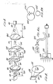
- Fig. 2 is a diagram of a laser diode of a diode laser;
- Fig. 3 shows a more detailed block diagram of the optical system of the exemplary embodiment of Fig. 1;
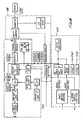
- Fig. 4 is a block diagram of the electrical safety and control system of the exemplary embodiment of Fig. 1;
- Fig. 5(A) is a diagram of the interface between two fiber optic cables; and
- Fig. 5(B) is a diagram of another exemplary embodiment of the subject invention.
- An exemplary embodiment of the subject invention as shown in Fig. 1. As illustrated in the Figure, the embodiment comprises diode laser 1, optical system 2, visible
light source 3, delivery system 4, and electronic control andsafety system 5. The diode laser and the visible light source are both coupled to the optical system. The diode laser haslaser diode 101 which produces a diode laser beam, and the visible light source produces a visible aiming beam. The diode laser beams is first shaped by the optical system, which then merges it with the visible aiming beam, and couples the merged beam to the delivery system. - The delivery system, as shown in the Figure, comprises fiber
optical cable 401 andendoprobe 402. As illustrated, the fiber optic cable is coupled to the optical system at one end, and is coupled to the endoprobe at the other end. The merged beam from the optical system is transmitted through the delivery system for ultimate delivery to a patient's retina. - Electronic control and
safety system 5 is coupled to all the other systems of the device. It both enables an operator to select a certain mode of operation, and power and timing parameters such as pulse width, energy level, and it also contains certain safety features. - In the embodiment of Fig. 1, the laser diode is either a Sony Model 303 WT, or a Spectra-Diode Labs Model 2431 H1. In fact, any diode can be used which produces laser light having a wavelength in the range of 700-840 nm. Since these diodes are so efficient, they only require current in the range of 1 ampere at a few volts to operate.
- In the embodiment of Fig. 1, the visible light source is a He-Ne laser, and the endoprobe is a Cooper Vision Laser Endoprobe (20 GA), Cat. No. 0101-0339. In fact, any visible light source will suffice that can be coupled through an optical fiber.
- A more detailed diagram of
diode 101 in the embodiment of Fig. 1 is illustrated in Fig. 2. As illustrated, the diode will emit alaser beam 102 from its rectangular end. The circumference of the beam of emitted light has two groups ofcomponent rays Rays 104 will diverge at a faster rate than rays 103.Fiber optic cable 401, on the other hand, is circular in shape at the ends, and it will be necessary to shape the emitted light into a circle before it can be effectively coupled to the fiber optic cable without significant losses of the emitted light. This is one of the functions of optical system 2. - A detailed diagram of optical system 2 of the embodiment of Fig. 1 is illustrated in Fig. 3. The reference numbers in Fig 3 are identical to those in Fig. 1. As illustrated, the system comprises collimating
lens 201,cylindrical lenses coupling lens 204. The system also comprisespolarizing beam splitter 205, andmirror 206, but these elements are only included in Fig. 1, not Fig 3. Also shown in the Figure arediode 101,rays fiber optic cable 401. - As illustrated, the optical system will affect
rays Rays 103 will be collimated, that is straightened by collimatinglens 201, and will then pass throughcylindrical lenses Coupling lens 204 will then focusrays 103 to an area approximately 200 microns in diameter. -
Rays 104 will also be collimated by collimatinglens 202.Cylindrical lenses rays 104 to equalize it with the spacing betweenrays 103. As illustrated in Fig. 2, the spacing is different because of the rectangular geometry of the edge of the diode.Lens 202 is a plano-concave lens, which causes the rays to diverge a certain amount, whilelens 203 is a corresponding plano-convex lens, which causes the rays to converge sufficiently so they are collimated, i.e. straight, again. As withrays 103,coupling lens 204 focuses the rays to an area having a diameter of approximately 200 microns. The net result is thatbeam 102 has been shaped into a circle having a diameter of 200 microns by the optical system. - In the embodiment of Fig. 3, collimating
lens 201 is a spherical lens having an f-number, which as is known in the art, is the ratio of the focal length of the lens to the diameter of the lens, of 1.0, although a lens having an f-number of any value less than one will suffice. -
Cylindrical lens 202 is a plano convex lens having a focal length of 60 centimeters (hereinafter "cm"), andcylindrical lens 203 is a plano convex lens having a focal length of -25 cm. As indicated earlier, the cylindrical lenses in combination act as an up-collimator, that is, they expand the spacing betweenrays 104 so that it equals the spacing betweenrays 103. In the embodiment of Figs. 1-3, the spacing betweenrays 103, at least initially, is 160 microns, and this is approximately 2½ times the initial spacing betweenrays 104. Therefore, any combination of cylindrical lenses will work in the embodiment of Figs. 1-3 as long as the collimation ratio of the two lenses, which is defined as the ratio of the absolute values of the focal length oflens 202 to that oflens 203, is approximately equal to the ratio of the spacing betweenrays 103 to the spacing betweenrays 104. As mentioned earlier, in the case of the embodiment of Figs. 1-3, the ratio of the spacing, which is determined by the geometry of the edge of the diode, is approximately 2½. The collimation ratio for the embodiment of Fig. 3 is 60/25, or 2.4. If the dimensions of the edge of the diode were changed however, the collimation ratio oflenses - The distance between the edge of
diode 101 andcollimating lens 201, indicated as 207 in Fig. 3, is also important. It should be equal to the focal length oflens 201, which in the embodiment of Figs. 1-3, is 4.5 millimeters (hereinafter "mm"). If the focal length oflens 201 is changed, the distance 207 between the diode and the lens should correspondingly be changed. However, the distance and hence focal length should not be too large, as this will require a larger diameter collimating lenses, which can be expensive. - The distance between the two cylindrical lenses of the up-collimator, that is
lenses lenses 202 andlens 203, which in the embodiment of Fig. 3, is 35 cm. - The distance between the coupling lens and the end of the fiber optic cable, indicated as 209 in Fig. 3, should be equal to the focal length of
coupling lens 204. - The focal length of the coupling lens is an important parameter, and depends on the size and numerical aperture of the fiber optical cable for which the lens is acting as a coupler. As is known, the numerical aperture is a measure of an angle known as the critical angle. The critical angle is defined with respect to normal incidence at the face of the end of the fiber optic cable. The angle of incidence of light which is incident upon the face of the end of the cable must be less than the critical angle in order to minimize reflective losses. In Fig. 3, for example, the incident light makes an angle of incidence ϑ at
face 210 of the end of thefiber optic cable 401. This angle must be below the critical angle, ϑc, associated with the fiber optic cable. As is known, the numerical aperture, N/A, is defined as the sine of one half of the critical angle. In other words: N/A = sin ½ϑc. The focal length must be chosen so that both the diameter of the focused beam at theface 210 of the fiber optic cable is less than or equal to the diameter of the fiber optic cable, and the angle of incidence of the beam is less than the critical angle of the cable. In the embodiment of Fig. 3, the focal length oflens 204, and hence thedistance 209, must be chosen so that the angle of incidence is below the critical angle offiber optic cable 401. - In the embodiment of Fig. 3, the focal length of
lens 204, and hence distance 209, is 15 mm. In addition, the diameter of the fiber optic cable is 200 microns, and the numerical aperture of the cable is .23. However, the diameter of the cable can be any value between 100-300 microns, and if changed from 200 microns, the focal length ofcoupling lens 204 should correspondingly be changed. A larger diameter is possible, but is not recommended, since it may lower the power density of the laser beam which is delivered to the patient's retina to the extent that photocoagulation is not achieved. - The end result of the optical system of Fig. 3 is that the optical system produces a beam of diode laser light having a diameter, 200 microns, approximately equal to the length of the rectangular edge of the diode, 160 microns. In other words, a magnification of approximately unity in this dimension is achieved.
- Besides its beam shaping function, the optical system of Fig. 3 also merges the diode laser beam with the visible aiming beam. The merging takes places at the polarizing beam splitter, which passes all linearly polarized light having a first polarization, but reflects all linearly polarized light having a second polarization which is rotated 90° from the first polarization. The beam-splitter has a first surface and a second surface, and mirror 406 directs the visible aiming beam to a particular point on the first surface of polarizing beam splitter 405. In addition, the polarizing beam splitter is situated such that the diode laser beam impinges upon the second surface of the beam splitter.
- The visible laser aiming beam will be linearly polarized in the second direction, and hence reflect from the first surface of the beam splitter. Moreover, the diode laser beam from the diode laser will be linearly polarized in the first direction and will transmit through the beam splitter and emerge at the second surface at the same point where the visible beam reflects. The result is that the diode laser beam and the visible aiming beam merge before impinging upon the coupling lens, and the merged beam is coupled to and transmitted through the delivery system to the patient's retina.
- Not shown in Fig. 3 is a liquid crystal shutter for adjusting the intensity of the aiming beam. The shutter comprises a liquid crystal followed by a sheet polarizer and is placed in the path of the visible aiming beam before it strikes the beam-splitter. As is known, the liquid crystal will rotate the polarization of the visible aiming beam depending on the voltage applied to it, while the sheet polarizer will act as a polarization filter for light of a particular polarization. The visible aiming beam will already be linearly polarized, and the liquid crystal will rotate the polarization depending on the voltage applied, so that the degree to which the light is filtered by the sheet polarizer will change. The result is that the intensity of the aiming beam can be adjusted by varying the voltage applied to the liquid crystal.
- The electronic control and safety system performs two functions. First, it allows an operator to control the mode of operation, and also the power and timing characteristics of the diode laser light which is delivered to the retina. Second, it provides a safety shutter for shutting off the diode laser beam when certain conditions are met. Regarding the control aspects, the system provides the following switches or controls:
- select operating mode, i.e. continuous, repeat pulse, or single pulse mode
- select laser power
- select pulse width
- select time between pulses in repeat pulse mode
- adjustment in visible aiming beam intensity
- counter for number of pulses delivered
- a counter reset button
- a "READY" button
- a foot switch. - The select mode switch enables an operator to deliver a continuous beam, a series of pulses, or a single pulse to the patient's retina. The power switch enables the operator to select the power delivered. The switch should enable the operator to select between .1-1 watts, which range is sufficient to achieve photocoagulation of abnormal retinal cells without affecting surrounding healthy tissue.
- The pulse width switch enables the operator to select the width of a single pulse. The switch should enable the operator to select a width of between 50 milliseconds (hereafter "msec") and 5 sec.
- The time between pulses is a parameter which depends on the treatment to be given to a particular patient, and any adjustment in aiming beam intensity is done simply for the convenience of the operator in locating and positioning the beam. The counter counts the number of pulses applied in repeat pulse mode, and the counter reset button simply resets the counter.
- The "READY" button is a safety feature and is used to control the safety shutter, which in Fig. 3, is placed between
coupling lens 204 and end face 210 offiber optic cable 401. Before the "READY" button is pushed, the safety shutter will block the diode laser beam, and prevent it from exiting the device to the delivery system. When the button is pushed, the shutter opens. - The foot switch is then used to control delivery of the diode laser light to the patient. When the foot switch is depressed, the light will be delivered according to the selected operating mode, and at the selected power level. If continuous mode is selected, the light will be delivered continuously. If single pulse mode is selected, a single pulse of light will be delivered at the selected single pulse width. If repeat pulse mode is selected, a pulse train will be delivered for as long as the switch is depressed, having a single pulse width and time between pulses as selected by the operator.
- Sensing means are also provided for sensing whether the fiber optic cable of the delivery system is attached to the device. If not, the sensing means causes the shutter to close, thereby preventing any diode laser light from accidentally being emitted from the device.
- In addition, feedback loop means are also provided for adjusting the current which flows through the diode until the selected output power of the diode laser light is achieved. This is to take account of changes in the current required to achieve a certain output power which may occur, for example, as the laser ages. The feedback loop means compares the actual output power level with the selected output power level, and adjusts the input current until the two are equal.
- A diagram of the electronic control and safety system is shown in Fig. 4. As shown in the Figure, the system comprises feedback loop means 501, safety means 502, and control means 503. As discussed above, the feedback loop means is coupled to the diode laser, and ensures that enough current is applied to the laser diode to achieve the selected output power. The safety means comprises a safety shutter which is placed between the coupling leans and the fiber optic connector. The safety shutter is coupled to an interlock sensor, which senses whether or not the delivery system is attached to the device. If not, the sensor causes the safety shutter to close. Finally, the control means are coupled to all the other components of the system. As mentioned earlier, the control means provides a capability for selecting operating mode, output power, pulse width, time between pulses, a "READY" button for opening the shutter and activating the foot switch, and a foot switch for controlling the delivery of the laser light.
- To operate the device, an operator first selects the mode pulse width, output power, and time between pulses, Since the "READY" button has not been pushed, no diode laser light is yet delivered. The visible aiming beam, on the other hand, is always on, and delivered to the patient's retina. The operator then looks through a microscope, and positions the location of the aiming beam by moving the endoprobe until the beam is situated at that portion of the retina which is to be photocoagulated. The operator then pushes the "START" button, and depresses the foot switch to deliver the diode laser light.
- An alternative embodiment comprises using a diode laser having a wavelength in the range of 600-700 nm, and typically 685 nm or less. Such a wavelength is short enough so that the light will be more visible, yet long enough so that the light will still be absorbed by the retinal cells. Since the diode laser light will be more visible, the visible
light source 3,mirror 206, andbeam splitter 205 can be eliminated. Of course, in this embodiment, the power of the delivered beam will have to be set low enough during the locating and positioning steps so that photo-coagulation of the retina will not occur, and then stepped up to a higher level after the beam has been properly positioned, when it is desired to photocoagulate the retina. Another control can be added to the device for this purpose. It is possible to directly couplefiber optic cable 401 todiode 101, and eliminate the remaining portion of the optical system used to shape the beam. Alternatively, this portion of the optical system can be left in place, to shape the laser beam, and couple it to the cable. In this case, the only step which is eliminated is the step of merging the beam with a visible, aiming beam. - A second alternative embodiment comprises using a laser diode which is combined with a visible LED on the same chip. This would also eliminate the necessity of a visible light source, and associated mirror and beam splitter for merging, since the diode laser would already produce a merged beam. As before, in this embodiment, the chip could be coupled directly to the fiber optic cable, or shaped by the optical system, and then coupled to the cable.
- A third alternative embodiment comprises locating and positioning the diode laser merely by visually positioning the endoprobe at the spot on the retina to be photocoagulated. As a result, the visible light source and associated optical elements for merging can be eliminated. As above, the laser beam can be directly coupled, or shaped before being coupled to the cable.
- In all the above embodiments, to directly couple the beam to the cable, it is only necessary to place the end of the cable in close proximity to the diode, and ensure that the diameter of the cable be greater than the length of the long rectangular edge of the diode. For example, if the diode edge is 160 microns, a fiber optic cable diameter of 200 microns can be used. Alternatively, the shape of the cable can be changed so it is elliptical, and matches the shape of the diode edge.
- A fourth embodiment comprises directly coupling the diode laser beam to an end of a first fiber optic cable which is coupled to an endoprobe at the other end for delivery. In addition, the visible aiming beam is directly coupled to a second fiber optic cable at one end, and the other end is directly coupled to an intermediate point of the first cable. In this embodiment, the entire optical system, both merging and shaping components, can be eliminated.
- As illustrated in Fig. 5(A), this embodiment comprises directly coupling one end of a first
fiber optic cable 1001 tolaser diode 1000, directly coupling one end of a secondfiber optic cable 1002 tovisible light source 1003, and then coupling the other end onto an intermediate point of the first cable. The diameter of the second cable should be chosen to be substantially less than the diameter of the first cable. As illustrated in Fig. 5(B), at theinterface 1001 between the two cables, there will be substantial losses of the diode laser beam, from the first cable 1004 to thesecond cable 1002, when the diameters are the same. However, when the diameter of thesecond cable 1002 is much smaller, the losses will be less. - For example, if the diameter of the first cable is 200 microns, the diameter of the second cable can be 6 microns.
- Additional advantages and modifications will readily occur to those skilled in the art. The invention in the broader aspects is not, therefore, limited to the specific details, representative methods, and illustrative examples shown and described. Accordingly, departures may be made from such details without departing from the spirit or scope of applicant's general inventive concept.
- Specifically, the invention is intended to encompass all embodiments of a laser diode device for transcutaneous laser photocoagulation of the retina including embodiments where the diode laser is or is not merged with a visible aiming beam, is or is not directly coupled to a fiber optic cable, is or is not shaped before being coupled to a fiber optic cable.
Claims (18)
1. A diode laser device for transcutaneous laser photocoagulation of the retina comprising:
a diode laser for producing a diode laser beam having a wavelength which is absorbed by retinal cells;
a visible light source for producing a visible, aiming beam;
a fiber optic cable having first and second ends, wherein the second end is coupled to an endoprobe;
optical means coupled to the diode laser, the visible light source, and the first end of said fiber optic cable, for: (a) shaping the diode laser beam; (b) merging the shaped diode laser beam with the visible, aiming beam; and (c) coupling the merged beam to the first end of said fiber optic cable.
2. A diode laser device for transcutaneous laser photocoagulation of the retina comprising:
a diode laser for producing a diode laser beam having a wavelength within the range of 600-700 nm; and
a fiber optic cable having first and second ends, wherein the second end is coupled to an endoprobe, and the first end is directly coupled to said diode laser.
a diode laser for producing a diode laser beam having a wavelength within the range of 600-700 nm; and
a fiber optic cable having first and second ends, wherein the second end is coupled to an endoprobe, and the first end is directly coupled to said diode laser.
3. The device of claim 2 wherein the diode laser beam has a wavelength of approximately 685 nm or less.
4. A diode laser device for transcutaneous laser photocoagulation of the retina comprising:
a diode laser having a chip combination for producing a diode laser beam having a wavelength which is absorbed by retinal cells which is merged with a visible, aiming beam; and
a fiber optic cable having first and second ends, wherein the second end is coupled to an endoprobe, and the first end is directly coupled to said chip combination.
5. A diode laser device for transcutaneous laser photocoagulation of the retina comprising:
a diode laser for producing a diode laser beam having a wavelength which is absorbed by retinal cells;
a visible light source for producing a visible, aiming beam;
a first fiber optic cable having a particular diameter, and having first and second ends, and an intermediate point between the first and second ends, wherein the second end is coupled to an endoprobe and the first end is directly coupled to said diode laser; and
a second fiber optic cable having a diameter which is substantially smaller than the diameter of said first fiber optic cable, and having first and second ends, wherein the first end is directly coupled to said visible light source, and the second end is coupled to said first fiber optic cable at an intermediate point between the first and second ends of said first cable.
6. A diode laser device for transcutaneous laser photocoagulation of the retina comprising:
a diode laser for producing a diode laser beam having a wavelength within the range of 600-700 nm;
a fiber optic cable having first and second ends, wherein the second end is coupled to an endoprobe; and
optical means coupled to the diode laser and the first end of said fiber optic cable, for (a) shaping the diode laser beam; and (b) coupling said shaped beam to the first end of said fiber optic cable.
7. The device of claim 6 wherein said wavelength is approximately 685 or less.
8. A diode laser device for transcutaneous laser photocoagulation of the retina comprising:
a diode laser having a chip combination for producing a diode laser beam having a wavelength which is absorbed by retinal cells which is merged with a visible, aiming beam;
a fiber optic cable having first and second ends, wherein the second end is coupled to an endoprobe: and
optical means coupled to the diode laser and the first end of said fiber optic cable, for (a) shaping the merged diode laser beam; and (b) coupling said shaped beam to the first end of said fiber optic cable.
9. A process for transcutaneous diode laser photocoagulation of a particular area of the retina comprising the steps of:
merging a diode laser beam having a wavelength which is absorbed by retinal cells with a visible, aiming beam;
coupling the merged beam into transcutaneous delivery means;
temporarily blocking the diode laser beam;
positioning the delivery means until the visible beam is located at the particular area of the retina to be photocoagulated; and
unblocking the diode laser beam to achieve photocoagulation at the particular area of the retina.
10. The process of claim 9 further comprising the step of shaping the diode laser beam before coupling the beam to said delivery means.
11. A process for transcutaneous diode laser photocoagulation of a particular area of the retina comprising the steps of:
coupling a diode laser beam having a wavelength which is absorbed by retinal cells into transcutaneous delivery means;
lowering the power of the beam to a level where photocoagulation is not achieved, and positioning the delivery means until the beam is located at the particular area of the retina to be photocoagulated; and
increasing the power of the diode laser beam to achieve photocoagulation at the particular area of the retina.
12. The process of claim 11 including the step of shaping the diode laser beam before coupling said beam to said delivery means.
13. The process of claim 11 wherein said diode laser beam has a wavelength of the range of 600-700 nm.
14. The process of claim 13 wherein said diode laser beam has a wavelength in the range of approximately 685 nm or less.
15. A process for transcutaneous laser coagulation of a particular area of the retina comprising the steps of:
coupling a diode laser beam having a wavelength which is absorbed by retinal cells into transcutaneous delivery means having a tip for insertion into the eye;
blocking the diode laser beam, and positioning the tip of the delivery means until the tip is located at the particular area of the retina to be coagulated; and
unblocking the diode laser beam to achieve photocoagulation at the particular area of the retina.
16. The process of claim 15 including the step of shaping the diode laser beam before coupling said beam to said delivery means.
17. The process of claim 9 wherein said diode laser beam has a wavelength in the range of 700-840 nm.
18. The device of any of the claims 1, 4, 5 or 8 wherein said diode laser beam has a wavelength in the range of 700-840 nm.
Applications Claiming Priority (2)
| Application Number | Priority Date | Filing Date | Title |
|---|---|---|---|
| US07/254,994 US5147349A (en) | 1988-10-07 | 1988-10-07 | Diode laser device for photocoagulation of the retina |
| US254994 | 1988-10-07 |
Publications (1)
| Publication Number | Publication Date |
|---|---|
| EP0363221A1 true EP0363221A1 (en) | 1990-04-11 |
Family
ID=22966391
Family Applications (1)
| Application Number | Title | Priority Date | Filing Date |
|---|---|---|---|
| EP89310262A Withdrawn EP0363221A1 (en) | 1988-10-07 | 1989-10-06 | A diode laser device for achieving transcutaneous laser photocoagulation of the retina |
Country Status (4)
| Country | Link |
|---|---|
| US (1) | US5147349A (en) |
| EP (1) | EP0363221A1 (en) |
| JP (1) | JPH04500921A (en) |
| WO (1) | WO1990003765A1 (en) |
Cited By (7)
| Publication number | Priority date | Publication date | Assignee | Title |
|---|---|---|---|---|
| US5185758A (en) * | 1989-11-28 | 1993-02-09 | Massachusetts Institute Of Technology | Multiple-laser pump optical system |
| US5319528A (en) * | 1990-08-01 | 1994-06-07 | Diomed Limited | High power light source |
| US5442487A (en) * | 1990-04-12 | 1995-08-15 | Nidek Co., Ltd. | Ophthalmic photocoagulating apparatus using a laser diode and a lens system for the apparatus |
| WO1997039375A1 (en) * | 1996-04-16 | 1997-10-23 | Leica Lasertechnik Gmbh | Point light source for a laser scanning microscope and process for feeding at least two laser beams of different wavelengths into a laser scanning microscope |
| DE19633185C2 (en) * | 1996-04-16 | 2000-06-15 | Leica Microsystems | Multi-colored point light source for a laser scanning microscope |
| EP1074232A1 (en) * | 1999-08-05 | 2001-02-07 | Nidek Co., Ltd. | Photocoagulation apparatus |
| EP1279375A1 (en) * | 2001-07-26 | 2003-01-29 | Carl Zeiss Meditec Limited | Portable laser system |
Families Citing this family (63)
| Publication number | Priority date | Publication date | Assignee | Title |
|---|---|---|---|---|
| JP3165146B2 (en) * | 1990-11-16 | 2001-05-14 | 株式会社ニデック | Laser therapy equipment |
| US5300063A (en) * | 1991-05-11 | 1994-04-05 | Nidek Co., Ltd. | Ophthalmic laser apparatus |
| US5217452A (en) * | 1992-05-18 | 1993-06-08 | Donnell Francis E O | Transscleral laser treatment of subretinal neovascularization |
| US5279298A (en) * | 1992-11-20 | 1994-01-18 | The Johns Hopkins University | Method and apparatus to identify and treat neovascular membranes in the eye |
| US5553629A (en) * | 1993-03-11 | 1996-09-10 | The United States Of America As Represented By The Secretary Of The Air Force | Portable medical laser pack system |
| US5397327A (en) * | 1993-07-27 | 1995-03-14 | Coherent, Inc. | Surgical laser handpiece for slit incisions |
| US20050111089A1 (en) * | 1994-07-15 | 2005-05-26 | Baer Stephen C. | Superresolving microscopy apparatus |
| JP3688339B2 (en) * | 1995-02-28 | 2005-08-24 | 株式会社ニデック | Laser treatment device |
| US7655002B2 (en) | 1996-03-21 | 2010-02-02 | Second Sight Laser Technologies, Inc. | Lenticular refractive surgery of presbyopia, other refractive errors, and cataract retardation |
| US6724958B1 (en) * | 1998-01-23 | 2004-04-20 | Science & Engineering Associates, Inc. | Handheld laser system emitting visible non-visible radiation |
| JP3866858B2 (en) * | 1998-04-30 | 2007-01-10 | 株式会社ニデック | Laser therapy device |
| US20060212025A1 (en) * | 1998-11-30 | 2006-09-21 | Light Bioscience, Llc | Method and apparatus for acne treatment |
| US6283956B1 (en) * | 1998-11-30 | 2001-09-04 | David H. McDaniels | Reduction, elimination, or stimulation of hair growth |
| US6676655B2 (en) * | 1998-11-30 | 2004-01-13 | Light Bioscience L.L.C. | Low intensity light therapy for the manipulation of fibroblast, and fibroblast-derived mammalian cells and collagen |
| US6936044B2 (en) * | 1998-11-30 | 2005-08-30 | Light Bioscience, Llc | Method and apparatus for the stimulation of hair growth |
| US6887260B1 (en) | 1998-11-30 | 2005-05-03 | Light Bioscience, Llc | Method and apparatus for acne treatment |
| US6267779B1 (en) * | 1999-03-29 | 2001-07-31 | Medelaser, Llc | Method and apparatus for therapeutic laser treatment |
| JP4359381B2 (en) * | 2000-06-30 | 2009-11-04 | 株式会社ニデック | Ophthalmic equipment |
| US20040267246A1 (en) * | 2002-02-01 | 2004-12-30 | Nidek Co., Ltd. | Laser treatment apparatus |
| JP2004105565A (en) * | 2002-09-20 | 2004-04-08 | Topcon Corp | Ophthalmologic photocoagulator |
| JP2004145031A (en) * | 2002-10-24 | 2004-05-20 | Nidek Co Ltd | Ablation apparatus by laser beam |
| US20040116909A1 (en) | 2002-12-11 | 2004-06-17 | Ceramoptec Industries Inc. | Multipurpose diode laser system for ophthalmic laser treatments |
| US11007373B1 (en) | 2002-12-20 | 2021-05-18 | James Andrew Ohneck | Photobiostimulation device and method of using same |
| KR20060041161A (en) | 2003-04-10 | 2006-05-11 | 라이트 바이오사이언스, 엘엘씨 | Photomodulation methods and devices for regulating cell proliferation and gene expression |
| KR101160343B1 (en) * | 2003-07-31 | 2012-06-26 | 젠틀웨이브즈 엘엘씨. | System and method for the photodynamic treatment of burns, wounds, and related skin disorders |
| JP2007520285A (en) | 2004-02-06 | 2007-07-26 | バロレ,ダニエル | Method and apparatus for treating mammalian tissue |
| US20060229689A1 (en) * | 2005-04-08 | 2006-10-12 | Led Technologies, Llc | LED therapy device |
| US20070027509A1 (en) * | 2005-07-29 | 2007-02-01 | Eisenberg Elliot S | Automated panretinal laser photocoagulation |
| US20070031777A1 (en) * | 2005-08-03 | 2007-02-08 | Bwt Property, Inc. | Multifunctional Dental Apparatus |
| US10842675B2 (en) | 2006-01-20 | 2020-11-24 | Lensar, Inc. | System and method for treating the structure of the human lens with a laser |
| US8262646B2 (en) | 2006-01-20 | 2012-09-11 | Lensar, Inc. | System and method for providing the shaped structural weakening of the human lens with a laser |
| US9889043B2 (en) | 2006-01-20 | 2018-02-13 | Lensar, Inc. | System and apparatus for delivering a laser beam to the lens of an eye |
| US9545338B2 (en) | 2006-01-20 | 2017-01-17 | Lensar, Llc. | System and method for improving the accommodative amplitude and increasing the refractive power of the human lens with a laser |
| DE102006019127A1 (en) * | 2006-04-25 | 2007-10-31 | Carl Zeiss Meditec Ag | Multi-wavelength laser system and method for ophthalmic applications |
| US20080172111A1 (en) | 2007-01-16 | 2008-07-17 | The General Hospital Corporation | Method and apparatus for selective photothermolysis of veins |
| WO2009146077A1 (en) * | 2008-04-03 | 2009-12-03 | The General Hospital Corporation | Method and apparatus for selective photothermolysis of veins |
| US7903706B2 (en) * | 2008-04-04 | 2011-03-08 | O'shaughnessy John | Compact, thermally stable multi-laser engine |
| US8975572B2 (en) | 2008-04-04 | 2015-03-10 | Cvi Laser, Llc | Compact, thermally stable fiber-optic array mountable to flow cell |
| US10114213B2 (en) | 2008-04-04 | 2018-10-30 | Cvi Laser, Llc | Laser systems and optical devices for manipulating laser beams |
| US9413130B2 (en) | 2012-12-12 | 2016-08-09 | Cvi Laser, Llc | Optical systems |
| US8480659B2 (en) | 2008-07-25 | 2013-07-09 | Lensar, Inc. | Method and system for removal and replacement of lens material from the lens of an eye |
| US8500723B2 (en) | 2008-07-25 | 2013-08-06 | Lensar, Inc. | Liquid filled index matching device for ophthalmic laser procedures |
| US20100106146A1 (en) * | 2008-10-24 | 2010-04-29 | Boitor Mihai I A | Hand-held portable laser surgical device |
| US20100318074A1 (en) * | 2009-06-10 | 2010-12-16 | Bruno Dacquay | Ophthalmic endoillumination using low-power laser light |
| EP2456384B1 (en) | 2009-07-24 | 2023-09-20 | LENSAR, Inc. | System for providing laser shot patterns to the lens of an eye |
| US8758332B2 (en) | 2009-07-24 | 2014-06-24 | Lensar, Inc. | Laser system and method for performing and sealing corneal incisions in the eye |
| EP2456385B1 (en) | 2009-07-24 | 2015-07-22 | Lensar, Inc. | System for performing ladar assisted procedures on the lens of an eye |
| US8617146B2 (en) | 2009-07-24 | 2013-12-31 | Lensar, Inc. | Laser system and method for correction of induced astigmatism |
| US8382745B2 (en) | 2009-07-24 | 2013-02-26 | Lensar, Inc. | Laser system and method for astigmatic corrections in association with cataract treatment |
| US9553422B2 (en) | 2009-08-04 | 2017-01-24 | Medical Coherence Llc | Multiple aperture hand-held laser therapy apparatus |
| US8790382B2 (en) * | 2009-08-04 | 2014-07-29 | Yonatan Gerlitz | Handheld low-level laser therapy apparatus |
| US8696653B2 (en) * | 2009-10-02 | 2014-04-15 | Cardiofocus, Inc. | Cardiac ablation system with pulsed aiming light |
| WO2011094678A1 (en) | 2010-02-01 | 2011-08-04 | Lensar, Inc. | Purkinjie image-based alignment of suction ring in ophthalmic applications |
| USD694890S1 (en) | 2010-10-15 | 2013-12-03 | Lensar, Inc. | Laser system for treatment of the eye |
| USD695408S1 (en) | 2010-10-15 | 2013-12-10 | Lensar, Inc. | Laser system for treatment of the eye |
| CN106974614B (en) | 2010-10-15 | 2019-04-26 | 雷萨公司 | The system and method for the scan control illumination of the structure of inside of eye |
| US9125677B2 (en) * | 2011-01-22 | 2015-09-08 | Arcuo Medical, Inc. | Diagnostic and feedback control system for efficacy and safety of laser application for tissue reshaping and regeneration |
| US10463541B2 (en) | 2011-03-25 | 2019-11-05 | Lensar, Inc. | System and method for correcting astigmatism using multiple paired arcuate laser generated corneal incisions |
| US9393154B2 (en) | 2011-10-28 | 2016-07-19 | Raymond I Myers | Laser methods for creating an antioxidant sink in the crystalline lens for the maintenance of eye health and physiology and slowing presbyopia development |
| US9606003B2 (en) | 2012-03-28 | 2017-03-28 | Yonatan Gerlitz | Clinical hand-held infrared thermometer with special optical configuration |
| US9946082B2 (en) | 2013-04-30 | 2018-04-17 | Medical Coherence Llc | Handheld, low-level laser apparatuses and methods for low-level laser beam production |
| WO2018146070A2 (en) | 2017-02-09 | 2018-08-16 | Norlase Aps | Apparatus for photothermal ophthalmic treatment |
| US11378808B2 (en) | 2018-07-18 | 2022-07-05 | Idex Health & Science Llc | Laser systems and optical devices for laser beam shaping |
Citations (6)
| Publication number | Priority date | Publication date | Assignee | Title |
|---|---|---|---|---|
| EP0131768A2 (en) * | 1983-06-17 | 1985-01-23 | Coherent, Inc. | A method and an apparatus for focusing an invisible beam of electromagnetic radiation |
| EP0194856A2 (en) * | 1985-03-11 | 1986-09-17 | Eclipse Surgical Technologies, Inc. | Surgical laser system |
| EP0248520A1 (en) * | 1986-04-24 | 1987-12-09 | Eye Research Institute Of Retina Foundation | Endophotocoagulation probe |
| FR2599961A1 (en) * | 1986-06-12 | 1987-12-18 | Morita Mfg | MEDICAL HANDPIECE WITH LASER. |
| EP0281161A2 (en) * | 1984-01-03 | 1988-09-07 | Medical Dynamics, Inc. | Cable assembly for laser endoscope apparatus |
| EP0293126A1 (en) * | 1987-05-20 | 1988-11-30 | Keeler Limited | Photocoagulation apparatus |
Family Cites Families (12)
| Publication number | Priority date | Publication date | Assignee | Title |
|---|---|---|---|---|
| JPS5778844A (en) * | 1980-11-04 | 1982-05-17 | Kogyo Gijutsuin | Lasre knife |
| US4633866A (en) * | 1981-11-23 | 1987-01-06 | Gholam Peyman | Ophthalmic laser surgical method |
| CH645801A5 (en) * | 1982-03-11 | 1984-10-31 | Lasag Ag | OPTICAL HEAD OF A SYSTEM FOR LASER RADIATION OBSERVATION AND TREATMENT OF THE EYE. |
| DE3306981C2 (en) * | 1983-02-28 | 1987-11-12 | Wolfram 8048 Haimhausen Weinberg | Device for the photocoagulation of biological tissue |
| US4503854A (en) * | 1983-06-16 | 1985-03-12 | Jako Geza J | Laser surgery |
| US4672969A (en) * | 1983-10-06 | 1987-06-16 | Sonomo Corporation | Laser healing method |
| US4561436A (en) * | 1983-10-28 | 1985-12-31 | Cooper Lasersonics, Inc. | Optical system for surgical ophthalmic laser instrument |
| US4686979A (en) * | 1984-01-09 | 1987-08-18 | The United States Of America As Represented By The United States Department Of Energy | Excimer laser phototherapy for the dissolution of abnormal growth |
| US4724835A (en) * | 1984-03-06 | 1988-02-16 | Pain Suppression Labs, Inc. | Laser therapeutic device |
| US4732448A (en) * | 1984-12-07 | 1988-03-22 | Advanced Interventional Systems, Inc. | Delivery system for high-energy pulsed ultraviolet laser light |
| JPS6218151U (en) * | 1985-07-18 | 1987-02-03 | ||
| US4818660A (en) * | 1987-11-04 | 1989-04-04 | E. I. Du Pont De Nemours And Company | Photohardenable electrostatic master having improved backtransfer and charge decay |
-
1988
- 1988-10-07 US US07/254,994 patent/US5147349A/en not_active Expired - Fee Related
-
1989
- 1989-10-06 EP EP89310262A patent/EP0363221A1/en not_active Withdrawn
- 1989-10-06 JP JP1510696A patent/JPH04500921A/en active Pending
- 1989-10-06 WO PCT/US1989/004298 patent/WO1990003765A1/en unknown
Patent Citations (6)
| Publication number | Priority date | Publication date | Assignee | Title |
|---|---|---|---|---|
| EP0131768A2 (en) * | 1983-06-17 | 1985-01-23 | Coherent, Inc. | A method and an apparatus for focusing an invisible beam of electromagnetic radiation |
| EP0281161A2 (en) * | 1984-01-03 | 1988-09-07 | Medical Dynamics, Inc. | Cable assembly for laser endoscope apparatus |
| EP0194856A2 (en) * | 1985-03-11 | 1986-09-17 | Eclipse Surgical Technologies, Inc. | Surgical laser system |
| EP0248520A1 (en) * | 1986-04-24 | 1987-12-09 | Eye Research Institute Of Retina Foundation | Endophotocoagulation probe |
| FR2599961A1 (en) * | 1986-06-12 | 1987-12-18 | Morita Mfg | MEDICAL HANDPIECE WITH LASER. |
| EP0293126A1 (en) * | 1987-05-20 | 1988-11-30 | Keeler Limited | Photocoagulation apparatus |
Cited By (10)
| Publication number | Priority date | Publication date | Assignee | Title |
|---|---|---|---|---|
| US5185758A (en) * | 1989-11-28 | 1993-02-09 | Massachusetts Institute Of Technology | Multiple-laser pump optical system |
| US5442487A (en) * | 1990-04-12 | 1995-08-15 | Nidek Co., Ltd. | Ophthalmic photocoagulating apparatus using a laser diode and a lens system for the apparatus |
| US5319528A (en) * | 1990-08-01 | 1994-06-07 | Diomed Limited | High power light source |
| US5463534A (en) * | 1990-08-01 | 1995-10-31 | Diomed Limited | High power light source |
| WO1997039375A1 (en) * | 1996-04-16 | 1997-10-23 | Leica Lasertechnik Gmbh | Point light source for a laser scanning microscope and process for feeding at least two laser beams of different wavelengths into a laser scanning microscope |
| DE19633185C2 (en) * | 1996-04-16 | 2000-06-15 | Leica Microsystems | Multi-colored point light source for a laser scanning microscope |
| US6222961B1 (en) | 1996-04-16 | 2001-04-24 | Leica Microsystems Heidelberg Gmbh | Point light source for a laser scanning microscope and process for feeding at least two different laser beams of different wavelengths into a laser scanning microscope |
| EP1074232A1 (en) * | 1999-08-05 | 2001-02-07 | Nidek Co., Ltd. | Photocoagulation apparatus |
| US6585722B1 (en) | 1999-08-05 | 2003-07-01 | Nidek Co., Ltd. | Photocoagulation apparatus |
| EP1279375A1 (en) * | 2001-07-26 | 2003-01-29 | Carl Zeiss Meditec Limited | Portable laser system |
Also Published As
| Publication number | Publication date |
|---|---|
| WO1990003765A1 (en) | 1990-04-19 |
| US5147349A (en) | 1992-09-15 |
| JPH04500921A (en) | 1992-02-20 |
Similar Documents
| Publication | Publication Date | Title |
|---|---|---|
| US5147349A (en) | Diode laser device for photocoagulation of the retina | |
| US8876808B2 (en) | Ophthalmic laser system | |
| US5423798A (en) | Ophthalmic surgical laser apparatus | |
| US8425495B2 (en) | Multipurpose diode laser system for ophthalmic laser treatments | |
| US20190365569A1 (en) | Apparatus for Photothermal Ophthalmic Treatment | |
| US5300063A (en) | Ophthalmic laser apparatus | |
| US4917486A (en) | Photocoagulation apparatus | |
| US5336216A (en) | Apparatus for delivering a defocused laser beam having a sharp-edged cross-section | |
| US6110165A (en) | Apparatus for laser treatment | |
| JPH0243502B2 (en) | ||
| WO1995015134A1 (en) | Laser system for reshaping the cornea | |
| US10702338B2 (en) | Laser system with pulse modulation and corresponding method of use | |
| US8066696B2 (en) | Ophthalmic laser treatment apparatus | |
| US20210299466A1 (en) | Method and apparatus for cyclo-scanner using surface emitting lasers or leds | |
| WO2014049132A1 (en) | Laser system for retinal treatment of macular degeneration | |
| US6575964B1 (en) | Selective aperture for laser delivery system for providing incision, tissue ablation and coagulation | |
| Brancato et al. | Diode and Nd: YAG laser contact transscleral cyclophotocoagulation in a human eye: a comparative histopathologic study of the lesions produced using a new fiber optic probe | |
| JP3197327B2 (en) | Ophthalmic laser device | |
| JP5628011B2 (en) | Laser therapy device | |
| WO2023062650A1 (en) | SINGLE AND/OR DUAL (532 AND/OR 577) nm LASER DELIVERY SYSTEM ATTACHED TO AN OPHTHALMIC MICROSCOPE | |
| KR100495480B1 (en) | Glaucoma treatment apparatus using a semiconductor laser | |
| CN113133868A (en) | Age-related macular degeneration treatment device | |
| JPH04197351A (en) | Semiconductor laser therapeutic device | |
| JPS60203246A (en) | Coagulative hemostatic apparatus |
Legal Events
| Date | Code | Title | Description |
|---|---|---|---|
| PUAI | Public reference made under article 153(3) epc to a published international application that has entered the european phase |
Free format text: ORIGINAL CODE: 0009012 |
|
| AK | Designated contracting states |
Kind code of ref document: A1 Designated state(s): CH DE FR GB LI NL |
|
| 17P | Request for examination filed |
Effective date: 19900327 |
|
| 17Q | First examination report despatched |
Effective date: 19910904 |
|
| STAA | Information on the status of an ep patent application or granted ep patent |
Free format text: STATUS: THE APPLICATION IS DEEMED TO BE WITHDRAWN |
|
| 18D | Application deemed to be withdrawn |
Effective date: 19920115 |