EP0363746A1 - Overcurrent protection device for electrical networks and apparatuses - Google Patents
Overcurrent protection device for electrical networks and apparatuses Download PDFInfo
- Publication number
- EP0363746A1 EP0363746A1 EP19890117991 EP89117991A EP0363746A1 EP 0363746 A1 EP0363746 A1 EP 0363746A1 EP 19890117991 EP19890117991 EP 19890117991 EP 89117991 A EP89117991 A EP 89117991A EP 0363746 A1 EP0363746 A1 EP 0363746A1
- Authority
- EP
- European Patent Office
- Prior art keywords
- thermistor
- contact
- heat
- overcurrent
- tripping
- Prior art date
- Legal status (The legal status is an assumption and is not a legal conclusion. Google has not performed a legal analysis and makes no representation as to the accuracy of the status listed.)
- Granted
Links
Images
Classifications
-
- H—ELECTRICITY
- H01—ELECTRIC ELEMENTS
- H01H—ELECTRIC SWITCHES; RELAYS; SELECTORS; EMERGENCY PROTECTIVE DEVICES
- H01H77/00—Protective overload circuit-breaking switches operated by excess current and requiring separate action for resetting
- H01H77/02—Protective overload circuit-breaking switches operated by excess current and requiring separate action for resetting in which the excess current itself provides the energy for opening the contacts, and having a separate reset mechanism
- H01H77/10—Protective overload circuit-breaking switches operated by excess current and requiring separate action for resetting in which the excess current itself provides the energy for opening the contacts, and having a separate reset mechanism with electrodynamic opening
-
- H—ELECTRICITY
- H01—ELECTRIC ELEMENTS
- H01C—RESISTORS
- H01C1/00—Details
- H01C1/08—Cooling, heating or ventilating arrangements
-
- H—ELECTRICITY
- H01—ELECTRIC ELEMENTS
- H01C—RESISTORS
- H01C1/00—Details
- H01C1/14—Terminals or tapping points or electrodes specially adapted for resistors; Arrangements of terminals or tapping points or electrodes on resistors
- H01C1/1406—Terminals or electrodes formed on resistive elements having positive temperature coefficient
-
- H—ELECTRICITY
- H01—ELECTRIC ELEMENTS
- H01C—RESISTORS
- H01C7/00—Non-adjustable resistors formed as one or more layers or coatings; Non-adjustable resistors made from powdered conducting material or powdered semi-conducting material with or without insulating material
- H01C7/02—Non-adjustable resistors formed as one or more layers or coatings; Non-adjustable resistors made from powdered conducting material or powdered semi-conducting material with or without insulating material having positive temperature coefficient
- H01C7/027—Non-adjustable resistors formed as one or more layers or coatings; Non-adjustable resistors made from powdered conducting material or powdered semi-conducting material with or without insulating material having positive temperature coefficient consisting of conducting or semi-conducting material dispersed in a non-conductive organic material
-
- H—ELECTRICITY
- H02—GENERATION; CONVERSION OR DISTRIBUTION OF ELECTRIC POWER
- H02H—EMERGENCY PROTECTIVE CIRCUIT ARRANGEMENTS
- H02H3/00—Emergency protective circuit arrangements for automatic disconnection directly responsive to an undesired change from normal electric working condition with or without subsequent reconnection ; integrated protection
- H02H3/02—Details
- H02H3/025—Disconnection after limiting, e.g. when limiting is not sufficient or for facilitating disconnection
-
- H—ELECTRICITY
- H02—GENERATION; CONVERSION OR DISTRIBUTION OF ELECTRIC POWER
- H02H—EMERGENCY PROTECTIVE CIRCUIT ARRANGEMENTS
- H02H9/00—Emergency protective circuit arrangements for limiting excess current or voltage without disconnection
- H02H9/02—Emergency protective circuit arrangements for limiting excess current or voltage without disconnection responsive to excess current
- H02H9/026—Current limitation using PTC resistors, i.e. resistors with a large positive temperature coefficient
Definitions
- the invention relates to a overcurrent protection device for electrical networks and apparatuses according to the precharacterising part of claim 1.
- the device is primarily intended for use in low-voltage networks and for low-voltage apparatuses, which are operating at rated voltages of a maximum of 1000 V.
- a device of the above-mentioned kind which is primarily designed for motor protection is previously known from the article "A New PTC Resistor for Power Applications" by R S Perkins et al, published in the journal IEEE Transactions on Components, Hybrids and Manufacturing Technology, Vol. CHMT-5, No. 2, June 1982, pp. 225-230.
- the device described in this article comprises a thermistor of ceramic type.
- This thermistor type has, inter alia, the disadvantage that a relatively great quantity of heat must be developed in the thermistor for it to change from its low-resistance to its high-resistance state. This large thermal inertia makes the described device less suitable for short-circuit protection.
- thermistor intended for overcurrent protection is known from the article "Polyswitch PTC Devices - A New Low-Resistance Conductive Polymer-Based PTC Device for Overcurrent Protection" by F A Doljack, also published in IEEE Transactions on Components, Hybrids and Manufacturing Technology, Vol. CHMT-4, No. 4, Dec. 1981, pp. 372-378.
- Thermistors of this type are also commercially available. They are built up of a polymeric material, for example high-pressure polyethylene, containing particles of an electrically conducting material, for example carbon black.
- thermoelectric thermistor compared with the ceramic thermistor resides from its resistance being monotonously with the temperature. In addition, it is considerably cheaper. However, commercially available thermistors of this type are designed for relatively low rated voltages and cannot, therefore, be used directly in distribution networks. In addition, the configuration and electrode connections of these thermistors are normally of such a nature that, upon a short circuit, the thermistors are subjected to great repulsive forces because of antiparallel current paths, whereby the electrodes are torn apart.
- the invention aims at developing an overcurrent protection device for electrical networks and apparatuses which is relatively simple and inexpensive and which allows that one and the same embodiment of the device can act as both as a motor protector and as a short-circuit protector.
- the invention suggests an overcurrent protection device for electrical networks and apparatuses according to the introductory part of claim 1, which is characterized by the features of the characterizing part of claim 1.
- the thermistor of the protection device with a thermal delay device, which comprises at least one heat-absorbing body making contact with the thermistor, the advantage is achieved that one and the same component can be used both for motor protection and for short-circuit protection.
- This entails considerable advantages from the points of view of cost and space.
- the device can replace conventional fuses as well as so-called automatic fuses (midget circuit-breakers) and it exhibits the advantages of both these types of fuses without suffering from their disadvantages, for example the limited life of the fuse and the limited breaking capacity of the automatic fuse upon a short circuit.
- polymer-based thermistors are usually designed for relatively low rated currents, for example 50-100 V. However, it has been found that these thermistors for brief periods are able to withstand considerably higher voltages, for example 400-500 V. This makes it possible to use this type of thermistors in networks with an operating voltage of, for example, 230 V, where voltage peaks of the above order of magnitude may occur across the thermistor upon breaking of high fault currents, for example in case of a short circuit.
- the protection device is provided with means which in such cases provide a rapid voltage relief of the thermistor.
- the contact device connected in series with the thermistor may be provided with a high-speed tripping device (a so-called kicker), which is adapted to influence the contact device directly for opening thereof when the thermistor has reached its transition temperature.
- a tripping device comprises the above-mentioned excitation coil device, which may suitably consist of two co-operating coils, one of which being fixed and the other displaceable. The two coils are connected in series in such a way that the current flows through their windings in opposite directions.
- the device for overcurrent protection shown in Figure 1 comprises a thermistor 1 with a positive temperature coefficient (PTC resistor) connected in series with a contact device 2.
- PTC resistor positive temperature coefficient
- An excitation coil device 3 Connected in parallel with the thermistor 1 is an excitation coil device 3, which forms part of a high-speed tripping device for the contact device 2.
- the tripping device is adapted to control the contact device 2 in case of an overcurrent.
- a varistor 9 for overvoltage protection may be arranged in parallel with the thermistor 1.
- the thermistor is of the polymer-based type mentioned above.
- Figure 2 shows the resistance R for such a thermistor 1 as a function of its temperature T.
- the resistance is low, for example 0.04 ⁇ , and increases slightly with the temperature.
- the thermistor 1 If the temperature of the thermistor 1 increases above said value, for example as a result of an overcurrent, the resistance increases more rapidly, and when a certain temperature T is exceeded, referred to below as the transition temperature, which may, for example, lie at about 120°C, the thermistor 1 abruptly changes from the a low- to a high-resistance state, in which its resistance may amount to 10 k ⁇ and more.
- the thermistor 1 may, for example, have the shape of a rectangular plate 4 and is provided with electrodes 5 making contact with the flat sides of the plate 4, as will be clear from Figure 3.
- the electrodes 5 substantially have the same square measure as the thermistor plate 4 but are considerably thicker than the latter. They are made of a material with a good electrical and thermal conductivity, for example of copper. Because they are made of this material, a thermal delay of the protection device according to Figure 1 is achieved when it is subjected to motor starting currents amounting to about 6-10 times the rated current. In this way a protection device can be provided which has a tripping characteristic complying with the requirements for motor protectors according to present national and international standards, for example IEC 159, and which, in addition, provides efficient short-circuit protection.
- Figure 4 shows, in principle, a tripping characteristic according to the above.
- region A which extends to about 10 times the rated current
- a thermal delay of the transition of the thermistor from the low- to the high-resistance state is desired, so that the device does not trip upon normal motor starting. This is achieved by the construction shown in Figure 3 in which the thermal capacity of the electrodes 5 is included in the "thermal capacity" of the thermistor.
- thermistor 1 By providing the thermistor 1 with relatively thick electrodes of a material having good electrical conductivity and connecting the connection leads 6 of the component to the mid-portion of the respective electrode 5, as will be clear from Figure 3, a favourable current distribution is obtained in the component, among other things from a mechanical point of view. With such an embodiment, the risk of the electrodes 5 being torn apart because of electrodynamic repulsive forces, caused by anti-parallel current paths, is minimized.
- FIG. 5 shows an example of how a tripping device for the contact device 2 according to Figure 1 may, in principle, be arranged.
- the tripping device according to Figure 5 is of a fast electrodynamic type comprising two coils 3a, 3b mounted around a fixed iron core 7, one coil 3a being fixed and the other coil 3b being displaceable along the iron core 7.
- the coils are series-connected in such a way that the currents in their windings flow in opposite directions around the iron core.
- the coils are influenced by a repulsive force F which is monotonously growing with the square of the current.
- the force provides a rapid dis placement of the movable coil 3b to the right, and via a carrier 8 of insulating material, the force is transmitted directly to the movable contact of the contact device 2.
- This contact is rotatably mounted at one end and articulately connected to the carrier 8 at a point between the ends of the contact. This brings about an amplification in the transmission of motion, so that a sufficiently large contact distance can be achieved with a relatively small displacement of the movable coil 3b. This means that the dependence of the electrodynamic forces on the relative position of the coils is minimized.
- the task of the iron core 7 is to strengthen the tripping force at the lower overcurrents.
- Figure 6 shows the course of the current in the case of breaking a short-circuit with the protection device according to Figure 1.
- the thermistor 1 has a low resistance, for example 0.04 ⁇ , and the whole operating current flows through it. If a short circuit occurs, the current increases very rapidly and the thermistor 1 is heated up.
- the thermistor 1 changes from its low- to its high-resistance state (the thermistor trips), the current thus being commutated to the parallel branch where it is limited by the impedance of the coil device 3 which has a relatively high resistance, for example 0.4 ⁇ .
- the coil device 3 may suitably be designed as shown in Figure 5.
- the breaking is relatively simple.
- the contact device can therefore be very simple and may not have to be provided with arc chutes.
- the rapid contact opening provides a rapid voltage relief of the thermistor 1, which therefore need not be designated to continuously withstand the operating voltage.
- the high-speed tripping device need not consist of two coils, as has been shown, but may instead consist of one coil which acts upon a movable magnet part for opening the contact device.
- the actuating member of the tripping device need not be mechanically connected to the movable contact but may consist of an insulating plate inserted between the movable and the fixed contact.
Abstract
Description
- The invention relates to a overcurrent protection device for electrical networks and apparatuses according to the precharacterising part of
claim 1. - The device is primarily intended for use in low-voltage networks and for low-voltage apparatuses, which are operating at rated voltages of a maximum of 1000 V.
- A device of the above-mentioned kind which is primarily designed for motor protection is previously known from the article "A New PTC Resistor for Power Applications" by R S Perkins et al, published in the journal IEEE Transactions on Components, Hybrids and Manufacturing Technology, Vol. CHMT-5, No. 2, June 1982, pp. 225-230. The device described in this article comprises a thermistor of ceramic type. This thermistor type has, inter alia, the disadvantage that a relatively great quantity of heat must be developed in the thermistor for it to change from its low-resistance to its high-resistance state. This large thermal inertia makes the described device less suitable for short-circuit protection. Another serious disadvantage is that this thermistor ex hibits a negative temperature coefficient when the temperature exceeds a certain value. In addition, a thermistor of ceramic type will easily crack if traversed by a short-circuit current, which is due to the thermal and mechanical stresses to which it is then subjected. In addition, a ceramic thermistor is relatively expensive.
- Another type of thermistor intended for overcurrent protection is known from the article "Polyswitch PTC Devices - A New Low-Resistance Conductive Polymer-Based PTC Device for Overcurrent Protection" by F A Doljack, also published in IEEE Transactions on Components, Hybrids and Manufacturing Technology, Vol. CHMT-4, No. 4, Dec. 1981, pp. 372-378. Thermistors of this type are also commercially available. They are built up of a polymeric material, for example high-pressure polyethylene, containing particles of an electrically conducting material, for example carbon black.
- An advantage of the polymer-based thermistor compared with the ceramic thermistor resides from its resistance being monotonously with the temperature. In addition, it is considerably cheaper. However, commercially available thermistors of this type are designed for relatively low rated voltages and cannot, therefore, be used directly in distribution networks. In addition, the configuration and electrode connections of these thermistors are normally of such a nature that, upon a short circuit, the thermistors are subjected to great repulsive forces because of antiparallel current paths, whereby the electrodes are torn apart. Furthermore, the transition energy for these thermistors is relatively low, which causes them, in the lower overcurrent range, to give an insufficient delay of the tripping in order to be used directly for motor protection. For the abovementioned reason, polymer-based thermistors have not, up to now, been employed within the electric power technique to any significant extent, but have mainly been used for protection of electronics equipment.
- The invention aims at developing an overcurrent protection device for electrical networks and apparatuses which is relatively simple and inexpensive and which allows that one and the same embodiment of the device can act as both as a motor protector and as a short-circuit protector.
- To achieve this aim the invention suggests an overcurrent protection device for electrical networks and apparatuses according to the introductory part of
claim 1, which is characterized by the features of the characterizing part ofclaim 1. - Further developments of the invention are characterized by the features of the additional claims.
- By providing the thermistor of the protection device with a thermal delay device, which comprises at least one heat-absorbing body making contact with the thermistor, the advantage is achieved that one and the same component can be used both for motor protection and for short-circuit protection. This entails considerable advantages from the points of view of cost and space. The device can replace conventional fuses as well as so-called automatic fuses (midget circuit-breakers) and it exhibits the advantages of both these types of fuses without suffering from their disadvantages, for example the limited life of the fuse and the limited breaking capacity of the automatic fuse upon a short circuit.
- Upon motor starting, the motor protector should not trip, within 5 seconds at a current of six times the rated current, according to present standards. If it is assumed that all heat that is developed in the thermistor during this time is transferred to the electrodes, the following electrode volume is required

Pmax = the maximum permissible loss power of the protection device
n = 6
tmax = 5 s
ρe = the density of the electrode material
Ce = the specific heat capacity of the electrode material
Tt = the transition temperature of the thermistor
Ta = the ambient temperature. - If the electrode material is copper, and with Pmax = 2 W, Tt = 120°C and Ta = 20°C, according to the above an electrode volume of about 10 cm³ is required. As can be seen, this volume is independent of the rated current of the protection device if the loss power Pmax is the same. However, in practice, a certain part of the developed energy is used for heating up the actual thermistor. In addition, in protection devices for low rated current the loss power may be considerably lower than the value stated. In certain cases it is therefore sufficient to provide an electrode volume which is considerably lower than the volume calculated above, for example one-tenth of that value.
- As mentioned above, polymer-based thermistors are usually designed for relatively low rated currents, for example 50-100 V. However, it has been found that these thermistors for brief periods are able to withstand considerably higher voltages, for example 400-500 V. This makes it possible to use this type of thermistors in networks with an operating voltage of, for example, 230 V, where voltage peaks of the above order of magnitude may occur across the thermistor upon breaking of high fault currents, for example in case of a short circuit. One condition for this, however, is that the protection device is provided with means which in such cases provide a rapid voltage relief of the thermistor. This can be achieved, for example, by a varistor connected in parallel with the thermistor, for example a ZnO varistor. Alternatively, according to a further development of the invention, the contact device connected in series with the thermistor may be provided with a high-speed tripping device (a so-called kicker), which is adapted to influence the contact device directly for opening thereof when the thermistor has reached its transition temperature. This tripping device comprises the above-mentioned excitation coil device, which may suitably consist of two co-operating coils, one of which being fixed and the other displaceable. The two coils are connected in series in such a way that the current flows through their windings in opposite directions. In the case of great fault currents, for example upon a short circuit, a strong repulsive force is generated which rapidly displaces the movable coil which, via an actuating member, brings about the opening of the contact device. The principal voltage in the circuit will thus appear only for a brief period across the thermistor and, after the breaking, lies across the contact device, which offers the necessary dielectric strength.
- By way of example, the invention will now be described in greater detail with reference to the accompanying drawings showing in
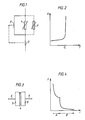
- Figure 1 a circuit diagram of a device for overcurrent protection according to the invention,
- Figure 2 a curve of resistance versus temperature for a thermistor forming part of the protection device according to Figure 1,
- Figure 3 a side view of a thermistor forming part of the protection device according to Figure 1,
- Figure 4 a curve of tripping time versus current for a protection device according to Figure 1,
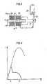
- Figure 5 an example of a high-speed tripping device for a contact device forming part of the protection device according to Figure 1,
- Figure 6 the variation of the current in case of a short-circuit breaking with a protection device according to Figure 1.
- The device for overcurrent protection shown in Figure 1 comprises a
thermistor 1 with a positive temperature coefficient (PTC resistor) connected in series with a contact device 2. Connected in parallel with thethermistor 1 is an excitation coil device 3, which forms part of a high-speed tripping device for the contact device 2. The tripping device is adapted to control the contact device 2 in case of an overcurrent. A varistor 9 for overvoltage protection may be arranged in parallel with thethermistor 1. - The thermistor is of the polymer-based type mentioned above. Figure 2 shows the resistance R for such a
thermistor 1 as a function of its temperature T. In the normal temperature working range of thethermistor 1, which may extend up to, for example, 80°C, the resistance is low, for example 0.04 Ω, and increases slightly with the temperature. If the temperature of thethermistor 1 increases above said value, for example as a result of an overcurrent, the resistance increases more rapidly, and when a certain temperature T is exceeded, referred to below as the transition temperature, which may, for example, lie at about 120°C, thethermistor 1 abruptly changes from the a low- to a high-resistance state, in which its resistance may amount to 10 kΩ and more. - The
thermistor 1 may, for example, have the shape of arectangular plate 4 and is provided withelectrodes 5 making contact with the flat sides of theplate 4, as will be clear from Figure 3. Theelectrodes 5 substantially have the same square measure as thethermistor plate 4 but are considerably thicker than the latter. They are made of a material with a good electrical and thermal conductivity, for example of copper. Because they are made of this material, a thermal delay of the protection device according to Figure 1 is achieved when it is subjected to motor starting currents amounting to about 6-10 times the rated current. In this way a protection device can be provided which has a tripping characteristic complying with the requirements for motor protectors according to present national and international standards, for example IEC 159, and which, in addition, provides efficient short-circuit protection. - Figure 4 shows, in principle, a tripping characteristic according to the above. In the region A, which extends to about 10 times the rated current, a thermal delay of the transition of the thermistor from the low- to the high-resistance state is desired, so that the device does not trip upon normal motor starting. This is achieved by the construction shown in Figure 3 in which the thermal capacity of the
electrodes 5 is included in the "thermal capacity" of the thermistor. - As a result, a greater quantity of heat and hence a longer time is required to attain the transition temperature of the thermistor material.
- Upon a short circuit, on the other hand, a tripping as rapid as possible is desired, which means that the required quantity of heat for the transition of the
thermistor 1 shall be as low as possible in this case. Also this is attained by the construction shown in Figure 3, since at the large currents occurring upon a short circuit (region B), the heat developed in thethermistor 1 cannot rapidly enough be transferred to theelectrodes 5 to delay the tripping of thethermistor 1. At short-circuit, therefore, the transition of the thermistor occurs at considerably lower heat quantity values than in the starting current region A. In certain cases, the required transition energy upon a short-circuit may amount to only one-tenth of the transition energy upon motor starting. - By providing the
thermistor 1 with relatively thick electrodes of a material having good electrical conductivity and connecting the connection leads 6 of the component to the mid-portion of therespective electrode 5, as will be clear from Figure 3, a favourable current distribution is obtained in the component, among other things from a mechanical point of view. With such an embodiment, the risk of theelectrodes 5 being torn apart because of electrodynamic repulsive forces, caused by anti-parallel current paths, is minimized. - Figure 5 shows an example of how a tripping device for the contact device 2 according to Figure 1 may, in principle, be arranged. The tripping device according to Figure 5 is of a fast electrodynamic type comprising two
coils 3a, 3b mounted around a fixed iron core 7, one coil 3a being fixed and theother coil 3b being displaceable along the iron core 7. The coils are series-connected in such a way that the currents in their windings flow in opposite directions around the iron core. Upon a flow of current, the coils are influenced by a repulsive force F which is monotonously growing with the square of the current. The force provides a rapid dis placement of themovable coil 3b to the right, and via a carrier 8 of insulating material, the force is transmitted directly to the movable contact of the contact device 2. This contact is rotatably mounted at one end and articulately connected to the carrier 8 at a point between the ends of the contact. This brings about an amplification in the transmission of motion, so that a sufficiently large contact distance can be achieved with a relatively small displacement of themovable coil 3b. This means that the dependence of the electrodynamic forces on the relative position of the coils is minimized. - The task of the iron core 7 is to strengthen the tripping force at the lower overcurrents.
- Figure 6 shows the course of the current in the case of breaking a short-circuit with the protection device according to Figure 1. During normal operation the
thermistor 1 has a low resistance, for example 0.04 Ω, and the whole operating current flows through it. If a short circuit occurs, the current increases very rapidly and thethermistor 1 is heated up. At time tt, which is only a few fractions of a millisecond after the occurrence of a short circuit, thethermistor 1 changes from its low- to its high-resistance state (the thermistor trips), the current thus being commutated to the parallel branch where it is limited by the impedance of the coil device 3 which has a relatively high resistance, for example 0.4 Ω. The coil device 3 may suitably be designed as shown in Figure 5. By the action of an electrodynamic force, a fast opening of the contact device is obtained at time tk, whereby the current is broken. Since the current has been limited to a relatively low value because of the impedance of the coil device 3 and, in addition, is mainly resistive, the breaking is relatively simple. The contact device can therefore be very simple and may not have to be provided with arc chutes. In addition, the rapid contact opening provides a rapid voltage relief of thethermistor 1, which therefore need not be designated to continuously withstand the operating voltage. - The invention is not limited to the embodiment shown but several variants are feasible within the scope of the claims. For example, the high-speed tripping device need not consist of two coils, as has been shown, but may instead consist of one coil which acts upon a movable magnet part for opening the contact device. The actuating member of the tripping device need not be mechanically connected to the movable contact but may consist of an insulating plate inserted between the movable and the fixed contact.
Claims (8)
Applications Claiming Priority (2)
| Application Number | Priority Date | Filing Date | Title |
|---|---|---|---|
| SE8803644 | 1988-10-13 | ||
| SE8803644A SE462250B (en) | 1988-10-13 | 1988-10-13 | DEVICE FOR OVERSEAS PROTECTION |
Publications (3)
| Publication Number | Publication Date |
|---|---|
| EP0363746A1 true EP0363746A1 (en) | 1990-04-18 |
| EP0363746B1 EP0363746B1 (en) | 1994-06-15 |
| EP0363746B2 EP0363746B2 (en) | 1998-04-29 |
Family
ID=20373614
Family Applications (1)
| Application Number | Title | Priority Date | Filing Date |
|---|---|---|---|
| EP19890117991 Expired - Lifetime EP0363746B2 (en) | 1988-10-13 | 1989-09-28 | Overcurrent protection device for electrical networks and apparatuses |
Country Status (5)
| Country | Link |
|---|---|
| EP (1) | EP0363746B2 (en) |
| JP (1) | JPH02163905A (en) |
| DE (1) | DE68916152T3 (en) |
| ES (1) | ES2057042T5 (en) |
| SE (1) | SE462250B (en) |
Cited By (16)
| Publication number | Priority date | Publication date | Assignee | Title |
|---|---|---|---|---|
| WO1991012643A1 (en) * | 1990-02-08 | 1991-08-22 | Asea Brown Boveri Ab | Device for motor and short-circuit protection |
| WO1993007667A1 (en) * | 1991-10-07 | 1993-04-15 | Asea Brown Boveri Ab | Device for overload and short-circuit protection in electric plants |
| EP0548606A2 (en) * | 1991-12-21 | 1993-06-30 | Asea Brown Boveri Ag | Resistance with PTC-behaviour |
| WO1994010734A1 (en) * | 1992-11-02 | 1994-05-11 | Seldim I Västerås Aktiebolag | Device for protection |
| EP0640995A1 (en) * | 1993-08-25 | 1995-03-01 | Abb Research Ltd. | Electrical resistor and application of this resistor in a current limiter |
| EP0655760A2 (en) * | 1993-11-30 | 1995-05-31 | ABBPATENT GmbH | Electrical switch device |
| US5436609A (en) * | 1990-09-28 | 1995-07-25 | Raychem Corporation | Electrical device |
| WO1997010636A2 (en) * | 1995-09-14 | 1997-03-20 | Raychem Corporation | Overcurrent protection circuit |
| DE19534442A1 (en) * | 1995-09-16 | 1997-03-27 | Abb Research Ltd | Over-current protection device for 11 to 17 kV networks |
| EP0809267A2 (en) * | 1996-05-20 | 1997-11-26 | Eaton Corporation | Circuit breaker incorporating trip coil as shunt resistor in parallel with current limiting polymer |
| WO1999017415A1 (en) * | 1997-09-26 | 1999-04-08 | Siemens Aktiengesellschaft | Power breaker for power supply and distribution |
| WO2000036624A1 (en) * | 1998-12-14 | 2000-06-22 | Square D Company | Remote controllable circuit breakers with positive temperature coefficient resistivity (ptc) elements |
| US6104587A (en) * | 1997-07-25 | 2000-08-15 | Banich; Ann | Electrical device comprising a conductive polymer |
| WO2004072992A1 (en) * | 2003-02-12 | 2004-08-26 | Alfa & Omega D.O.O. | Varistor protective insertion |
| EP1720183A1 (en) * | 2004-02-06 | 2006-11-08 | Tyco Electronics Raychem K.K. | Switch and device using the switch |
| US20170214312A1 (en) * | 2014-04-08 | 2017-07-27 | Siemens Aktiengesellschaft | Method for protecting an electrical modular unit from overcurrent damage |
Families Citing this family (4)
| Publication number | Priority date | Publication date | Assignee | Title |
|---|---|---|---|---|
| US6128168A (en) | 1998-01-14 | 2000-10-03 | General Electric Company | Circuit breaker with improved arc interruption function |
| US6144540A (en) | 1999-03-09 | 2000-11-07 | General Electric Company | Current suppressing circuit breaker unit for inductive motor protection |
| US6157286A (en) | 1999-04-05 | 2000-12-05 | General Electric Company | High voltage current limiting device |
| KR102305558B1 (en) * | 2019-10-04 | 2021-09-27 | 탑인더스트리(주) | Distribution board and motor control panel with high temperature stop function |
Citations (3)
| Publication number | Priority date | Publication date | Assignee | Title |
|---|---|---|---|---|
| US3914727A (en) * | 1974-01-02 | 1975-10-21 | Sprague Electric Co | Positive-temperature-coefficient-resistor package |
| DE2935807A1 (en) * | 1979-09-05 | 1981-04-02 | Brown, Boveri & Cie Ag, 6800 Mannheim | Overload protection circuit - has PTC resistor in series with load and shunted by overload warning lamp |
| EP0087884A1 (en) * | 1982-02-17 | 1983-09-07 | RAYCHEM CORPORATION (a California corporation) | PTC circuit protection device |
-
1988
- 1988-10-13 SE SE8803644A patent/SE462250B/en not_active IP Right Cessation
-
1989
- 1989-09-28 EP EP19890117991 patent/EP0363746B2/en not_active Expired - Lifetime
- 1989-09-28 ES ES89117991T patent/ES2057042T5/en not_active Expired - Lifetime
- 1989-09-28 DE DE1989616152 patent/DE68916152T3/en not_active Expired - Fee Related
- 1989-10-11 JP JP26482989A patent/JPH02163905A/en active Pending
Patent Citations (3)
| Publication number | Priority date | Publication date | Assignee | Title |
|---|---|---|---|---|
| US3914727A (en) * | 1974-01-02 | 1975-10-21 | Sprague Electric Co | Positive-temperature-coefficient-resistor package |
| DE2935807A1 (en) * | 1979-09-05 | 1981-04-02 | Brown, Boveri & Cie Ag, 6800 Mannheim | Overload protection circuit - has PTC resistor in series with load and shunted by overload warning lamp |
| EP0087884A1 (en) * | 1982-02-17 | 1983-09-07 | RAYCHEM CORPORATION (a California corporation) | PTC circuit protection device |
Cited By (27)
| Publication number | Priority date | Publication date | Assignee | Title |
|---|---|---|---|---|
| US5296996A (en) * | 1990-02-08 | 1994-03-22 | Asea Brown Boveri Ab | Device for motor and short-circuit protection |
| WO1991012643A1 (en) * | 1990-02-08 | 1991-08-22 | Asea Brown Boveri Ab | Device for motor and short-circuit protection |
| US5436609A (en) * | 1990-09-28 | 1995-07-25 | Raychem Corporation | Electrical device |
| WO1993007667A1 (en) * | 1991-10-07 | 1993-04-15 | Asea Brown Boveri Ab | Device for overload and short-circuit protection in electric plants |
| EP0548606A2 (en) * | 1991-12-21 | 1993-06-30 | Asea Brown Boveri Ag | Resistance with PTC-behaviour |
| EP0548606A3 (en) * | 1991-12-21 | 1994-04-06 | Asea Brown Boveri | |
| WO1994010734A1 (en) * | 1992-11-02 | 1994-05-11 | Seldim I Västerås Aktiebolag | Device for protection |
| US5602520A (en) * | 1993-08-25 | 1997-02-11 | Abb Research Ltd. | Electrical resistance element and use of this resistance element in a current limiter |
| EP0640995A1 (en) * | 1993-08-25 | 1995-03-01 | Abb Research Ltd. | Electrical resistor and application of this resistor in a current limiter |
| EP0655760A3 (en) * | 1993-11-30 | 1997-06-04 | Abb Patent Gmbh | Electrical switch device. |
| EP0655760A2 (en) * | 1993-11-30 | 1995-05-31 | ABBPATENT GmbH | Electrical switch device |
| WO1997010636A3 (en) * | 1995-09-14 | 1997-07-17 | Raychem Corp | Overcurrent protection circuit |
| US5864458A (en) * | 1995-09-14 | 1999-01-26 | Raychem Corporation | Overcurrent protection circuits comprising combinations of PTC devices and switches |
| WO1997010636A2 (en) * | 1995-09-14 | 1997-03-20 | Raychem Corporation | Overcurrent protection circuit |
| DE19534442A1 (en) * | 1995-09-16 | 1997-03-27 | Abb Research Ltd | Over-current protection device for 11 to 17 kV networks |
| EP0809267A2 (en) * | 1996-05-20 | 1997-11-26 | Eaton Corporation | Circuit breaker incorporating trip coil as shunt resistor in parallel with current limiting polymer |
| EP0809267A3 (en) * | 1996-05-20 | 1998-10-21 | Eaton Corporation | Circuit breaker incorporating trip coil as shunt resistor in parallel with current limiting polymer |
| US6104587A (en) * | 1997-07-25 | 2000-08-15 | Banich; Ann | Electrical device comprising a conductive polymer |
| WO1999017415A1 (en) * | 1997-09-26 | 1999-04-08 | Siemens Aktiengesellschaft | Power breaker for power supply and distribution |
| WO2000036624A1 (en) * | 1998-12-14 | 2000-06-22 | Square D Company | Remote controllable circuit breakers with positive temperature coefficient resistivity (ptc) elements |
| WO2004072992A1 (en) * | 2003-02-12 | 2004-08-26 | Alfa & Omega D.O.O. | Varistor protective insertion |
| EP1720183A1 (en) * | 2004-02-06 | 2006-11-08 | Tyco Electronics Raychem K.K. | Switch and device using the switch |
| EP1720183A4 (en) * | 2004-02-06 | 2007-06-20 | Tyco Electronics Raychem Kk | Switch and device using the switch |
| CN1918679B (en) * | 2004-02-06 | 2011-10-05 | 泰科电子雷伊化学株式会社 | Switch and device using the switch |
| US8395062B2 (en) | 2004-02-06 | 2013-03-12 | Tyco Electronics Raychem Kk | Switch and device using the switch |
| US20170214312A1 (en) * | 2014-04-08 | 2017-07-27 | Siemens Aktiengesellschaft | Method for protecting an electrical modular unit from overcurrent damage |
| US10530240B2 (en) * | 2014-04-08 | 2020-01-07 | Siemens Aktiengesellschaft | Method for protecting an electrical modular unit from overcurrent damage |
Also Published As
| Publication number | Publication date |
|---|---|
| DE68916152T2 (en) | 1995-01-12 |
| ES2057042T3 (en) | 1994-10-16 |
| SE462250B (en) | 1990-05-21 |
| ES2057042T5 (en) | 1998-10-01 |
| JPH02163905A (en) | 1990-06-25 |
| DE68916152T3 (en) | 1998-12-10 |
| SE8803644D0 (en) | 1988-10-13 |
| EP0363746B1 (en) | 1994-06-15 |
| DE68916152D1 (en) | 1994-07-21 |
| SE8803644L (en) | 1990-04-14 |
| EP0363746B2 (en) | 1998-04-29 |
Similar Documents
| Publication | Publication Date | Title |
|---|---|---|
| US5296996A (en) | Device for motor and short-circuit protection | |
| EP0363746A1 (en) | Overcurrent protection device for electrical networks and apparatuses | |
| US5644283A (en) | Variable high-current resistor, especially for use as protective element in power switching applications & circuit making use of high-current resistor | |
| US5877467A (en) | Circuit breaker current limiting arc runner | |
| US6342994B1 (en) | Protective device against excessive currents, in particular for resettable protection of a controlled switch | |
| CA1331399C (en) | Assemblies of ptc circuit protection devices | |
| US5629658A (en) | Methods of arc suppression and circuit breakers with electronic alarmers | |
| US5859578A (en) | Current limiting shunt for current limiting circuit breakers | |
| CN102763187B (en) | Assembly for protecting against power surges | |
| EP0667050B1 (en) | Device for protection against overcurrents | |
| CN105684120A (en) | Protective device | |
| JP2001515652A (en) | Circuit breaker with improved arc breaking performance | |
| US7362207B2 (en) | Electrical switching apparatus and limiter including trip indicator member | |
| CA2721512A1 (en) | Circuit protection device | |
| US5428195A (en) | Current limiter unit for molded case circuit breakers | |
| US5920251A (en) | Reusable fuse using current limiting polymer | |
| SE470118B (en) | Device for protection against overcurrent in electrical circuits | |
| WO1993007667A1 (en) | Device for overload and short-circuit protection in electric plants | |
| US6020802A (en) | Circuit breaker including two magnetic coils and a positive temperature coefficient resistivity element | |
| AU2008201800B2 (en) | Trip indicator member, and limiter and electrical switching apparatus including a plurality of trip indicator members | |
| US6414256B1 (en) | Current limiting circuit breaker | |
| US6144540A (en) | Current suppressing circuit breaker unit for inductive motor protection | |
| JP4368039B2 (en) | Thermal fuse having a self-heating element and a battery pack incorporating the thermal fuse | |
| US20020196120A1 (en) | Non-energy limiting class 2 transformer with positive temperature protection | |
| JP3797629B2 (en) | Current-limiting circuit breaker |
Legal Events
| Date | Code | Title | Description |
|---|---|---|---|
| PUAI | Public reference made under article 153(3) epc to a published international application that has entered the european phase |
Free format text: ORIGINAL CODE: 0009012 |
|
| AK | Designated contracting states |
Kind code of ref document: A1 Designated state(s): DE ES FR GB IT |
|
| 17P | Request for examination filed |
Effective date: 19900928 |
|
| 17Q | First examination report despatched |
Effective date: 19920910 |
|
| GRAA | (expected) grant |
Free format text: ORIGINAL CODE: 0009210 |
|
| AK | Designated contracting states |
Kind code of ref document: B1 Designated state(s): DE ES FR GB IT |
|
| REF | Corresponds to: |
Ref document number: 68916152 Country of ref document: DE Date of ref document: 19940721 |
|
| ITF | It: translation for a ep patent filed |
Owner name: JACOBACCI CASETTA & PERANI S.P.A. |
|
| ET | Fr: translation filed | ||
| REG | Reference to a national code |
Ref country code: ES Ref legal event code: FG2A Ref document number: 2057042 Country of ref document: ES Kind code of ref document: T3 |
|
| PLBI | Opposition filed |
Free format text: ORIGINAL CODE: 0009260 |
|
| 26 | Opposition filed |
Opponent name: RAYCHEM CORPORATION (A DELAWARE CORPORATION) Effective date: 19950313 |
|
| PLAW | Interlocutory decision in opposition |
Free format text: ORIGINAL CODE: EPIDOS IDOP |
|
| APAE | Appeal reference modified |
Free format text: ORIGINAL CODE: EPIDOS REFNO |
|
| APAC | Appeal dossier modified |
Free format text: ORIGINAL CODE: EPIDOS NOAPO |
|
| APAC | Appeal dossier modified |
Free format text: ORIGINAL CODE: EPIDOS NOAPO |
|
| APAC | Appeal dossier modified |
Free format text: ORIGINAL CODE: EPIDOS NOAPO |
|
| PLAW | Interlocutory decision in opposition |
Free format text: ORIGINAL CODE: EPIDOS IDOP |
|
| PLAW | Interlocutory decision in opposition |
Free format text: ORIGINAL CODE: EPIDOS IDOP |
|
| PUAH | Patent maintained in amended form |
Free format text: ORIGINAL CODE: 0009272 |
|
| STAA | Information on the status of an ep patent application or granted ep patent |
Free format text: STATUS: PATENT MAINTAINED AS AMENDED |
|
| 27A | Patent maintained in amended form |
Effective date: 19980429 |
|
| AK | Designated contracting states |
Kind code of ref document: B2 Designated state(s): DE ES FR GB IT |
|
| ITF | It: translation for a ep patent filed |
Owner name: JACOBACCI & PERANI S.P.A. |
|
| ET3 | Fr: translation filed ** decision concerning opposition | ||
| REG | Reference to a national code |
Ref country code: ES Ref legal event code: DC2A Kind code of ref document: T5 Effective date: 19980729 |
|
| REG | Reference to a national code |
Ref country code: GB Ref legal event code: IF02 |
|
| APAH | Appeal reference modified |
Free format text: ORIGINAL CODE: EPIDOSCREFNO |
|
| PGFP | Annual fee paid to national office [announced via postgrant information from national office to epo] |
Ref country code: FR Payment date: 20060908 Year of fee payment: 18 |
|
| PGFP | Annual fee paid to national office [announced via postgrant information from national office to epo] |
Ref country code: DE Payment date: 20060922 Year of fee payment: 18 |
|
| PGFP | Annual fee paid to national office [announced via postgrant information from national office to epo] |
Ref country code: GB Payment date: 20060927 Year of fee payment: 18 |
|
| PGFP | Annual fee paid to national office [announced via postgrant information from national office to epo] |
Ref country code: IT Payment date: 20060930 Year of fee payment: 18 |
|
| PGFP | Annual fee paid to national office [announced via postgrant information from national office to epo] |
Ref country code: ES Payment date: 20061023 Year of fee payment: 18 |
|
| GBPC | Gb: european patent ceased through non-payment of renewal fee |
Effective date: 20070928 |
|
| PG25 | Lapsed in a contracting state [announced via postgrant information from national office to epo] |
Ref country code: DE Free format text: LAPSE BECAUSE OF NON-PAYMENT OF DUE FEES Effective date: 20080401 |
|
| REG | Reference to a national code |
Ref country code: FR Ref legal event code: ST Effective date: 20080531 |
|
| PG25 | Lapsed in a contracting state [announced via postgrant information from national office to epo] |
Ref country code: FR Free format text: LAPSE BECAUSE OF NON-PAYMENT OF DUE FEES Effective date: 20071001 |
|
| PG25 | Lapsed in a contracting state [announced via postgrant information from national office to epo] |
Ref country code: GB Free format text: LAPSE BECAUSE OF NON-PAYMENT OF DUE FEES Effective date: 20070928 |
|
| REG | Reference to a national code |
Ref country code: ES Ref legal event code: FD2A Effective date: 20070929 |
|
| PG25 | Lapsed in a contracting state [announced via postgrant information from national office to epo] |
Ref country code: ES Free format text: LAPSE BECAUSE OF NON-PAYMENT OF DUE FEES Effective date: 20070929 |
|
| PG25 | Lapsed in a contracting state [announced via postgrant information from national office to epo] |
Ref country code: IT Free format text: LAPSE BECAUSE OF NON-PAYMENT OF DUE FEES Effective date: 20070928 |