EP0363828A2 - Method and apparatus for adaptive learning type general purpose image measurement and recognition - Google Patents
Method and apparatus for adaptive learning type general purpose image measurement and recognition Download PDFInfo
- Publication number
- EP0363828A2 EP0363828A2 EP89118529A EP89118529A EP0363828A2 EP 0363828 A2 EP0363828 A2 EP 0363828A2 EP 89118529 A EP89118529 A EP 89118529A EP 89118529 A EP89118529 A EP 89118529A EP 0363828 A2 EP0363828 A2 EP 0363828A2
- Authority
- EP
- European Patent Office
- Prior art keywords
- measurement
- general purpose
- type general
- adaptive learning
- learning type
- Prior art date
- Legal status (The legal status is an assumption and is not a legal conclusion. Google has not performed a legal analysis and makes no representation as to the accuracy of the status listed.)
- Granted
Links
Images


Classifications
-
- G—PHYSICS
- G06—COMPUTING; CALCULATING OR COUNTING
- G06V—IMAGE OR VIDEO RECOGNITION OR UNDERSTANDING
- G06V10/00—Arrangements for image or video recognition or understanding
- G06V10/40—Extraction of image or video features
- G06V10/42—Global feature extraction by analysis of the whole pattern, e.g. using frequency domain transformations or autocorrelation
-
- G—PHYSICS
- G06—COMPUTING; CALCULATING OR COUNTING
- G06F—ELECTRIC DIGITAL DATA PROCESSING
- G06F18/00—Pattern recognition
- G06F18/20—Analysing
- G06F18/21—Design or setup of recognition systems or techniques; Extraction of features in feature space; Blind source separation
-
- G—PHYSICS
- G06—COMPUTING; CALCULATING OR COUNTING
- G06V—IMAGE OR VIDEO RECOGNITION OR UNDERSTANDING
- G06V10/00—Arrangements for image or video recognition or understanding
- G06V10/70—Arrangements for image or video recognition or understanding using pattern recognition or machine learning
Abstract
Description
- This invention relates to a method and apparatus for various image measurements (including counting and discrimination) of the shapes and numbers of objects expressed in binary images in the fields of image measurement such as inspection or identification of parts on production lines, material or medical fields, and more particularly to a general or universal purpose image measurement and recognition device which either counts or measures geometric characteristics (such as a number or length of a circumference) of objects as the two-dimensional patterns at a high speed or discriminates two-dimensional patterns at a high speed by learning and to a method therefor.
- Further, according to this invention, the method is largely used as the general purpose image measurement and recognition device in which adaptive learning function and high speed of real time are requested.
- In the prior art, an image measurement device is realized by sequentially and serially combining image processing techniques which are judged necessary in order to achieve particular tasks as shown in FIG.1 (Sequential and Procedural Method). For example, in order to count the number of two types of particles in binary image including a large number of particles of two different radii, all the particles (black circles) on a screen (white background) are first detected, and discriminated by attaching labels (numbers) to the respective particles. Next, their diameters, areas and so on are respectively measured, the type of the groups is decided to which each particle belongs, and the decision numbers are counted to finally obtain the respective numbers of particles of two different groups.
- Since the above prior art devices are realized by combining various and complicated image processing techniques sequentially, the processing takes a long time for the calculation, and the whole system inevitably becomes large and complicated, posing a problem in high speed processing. The most critical problem inherent to these devices is that the duration of time necessary for the processing increases in proportion to the degree of complexity (e.g. the number of the particles in the above example) of the objective images. Another problem lies in that since these series of processings are those each prepared to achieve a specific and predetermined purpose, the device is dedicated solely to the predetermined purposes, and techniques should be modified for different uses. Moreover, these devices can be applied only to problems which are clearly known what is to be measured by which technique in what procedure.
- Besides the above mentioned serial measurement method, there is proposed a parallel and adaptive method such as the models of "perceptron" or "neural networks" in pattern recognition. FIG.2 shows the structure of such the neural networks which is modelled after the information processing by the brain. In the figure, layers (input layer, intermediate layer and output layer) having a large number of elements modelled after characteristics of neurons are connected in multilayers, and their connection coefficients are set as variable weights (parameters). In order to output desirable results (measured results) for the inputs, a large number of data for the learning are sequentially inputted, and the above connection coefficients are sequentially modified every time an error is made in output.
- However, the above-mentioned measuring method is slow in convergence speed of the learning although it is fast in measuring processing because of the parallel processing. Further, local optimal solutions sometimes make obtaining the global optimal result difficult. Although the measuring method is adaptive and universal, the practical application inevitably takes a trial-and-error manner because it is not known what number of elements should be combined in what way to a particular problem or what should be inputted. The elements used in such the neural networks are restricted to use the input and output signals in the two values of "0" and "1" or the values therebetween on the model of neuron cells. Therefore, the
weighted sum 10 of a large number of inputs is non-linearly transformed 11 before becoming one output as shown in FIG.3. Although the expression of information in this type of measuring method is significant as a model of a neurological information processing, it is not quite important in practice and is rather limitative and inefficient. Therefore, the measuring method has some problem and limitation as a practical image measuring device. - U.S. Patent 4,288,779 corresponding to Japanese Patent Publication (KOKOKU) No. 47064/1983 discloses a system which can discriminate two-dimensional patterns at a high speed and measure geometrical characteristics of the patterns at a high speed. However, since the measuring method must have other machines do arithmetic operations necessary for the character recognition to have the results in advance, its usage is limited. It is limited in usages for reading out the characters because it solely aims at providing the characteristics which do not need segmentation of a character, and it is not quite adaptive to the changes in the size and forms of the objective patterns. Therefore, the measuring method is not quite adaptive nor universal when a user wishes to apply it to a particular need at his shop. Since it is generally not easy to predict environment conditions (disturbance, for example mistiness and image quality) and so on of the device in advance, it is impossible to prepare a method which is most adaptive and optimal to particular conditions.
- This invention was conceived to eliminate such problems encountered in the prior art and aims at providing an adaptive learning type general purpose image measurement and recognition method and apparatus which extracts features in two stages of a relatively simple structure based on the observation of basic and principle conditions of the image measurement, and adaptively measures the images for arbitrary objects or usages suitable for environments by high speed learning.
- According to one aspect of this invention, for achieving the objects described above, there is provided an adaptive learning type general purpose image measurement and recognition method which comprises the steps of extracting a large number of basic initial feature which are based on Nth order autocorrelation and invariant to parallel displacement of an object to be caught in an image frame and which have additivity with respect to the image frame, and performing statistical features extraction having learning function used multivariate analysis methods based on the extracted initial features to thereby enable use for various types of measurement adaptively.
- According to another aspect of this invention, there is provided an adaptive learning type general purpose image measurement and recognition apparatus which comprises a pick-up means to pick-up objects of measurement in two-dimension, an image cutting-out means which partially cuts out video signals of said picked-up images, a window signal generating means which generates a window signal for designating a measurement scope, a correlating means which computers Nth order autocorrelation of said cut-out data within the scopes of said window signal, a memory means which stores coefficients of said autocorrelation, and an arithmetic controlling means which controls said respective as well as calculates multivariate analysis based on said computed values to thereby enable use for various types of measurement adaptively.
- The nature, principle and utility of the invention will become more apparent from the following detailed description when read in conjunction with the accompanying drawings.
- In the accompanying drawings:
- FIG.1 is a conceptual block diagram to show the conventional serial measurement method;
- FIGs.2 and 3 are charts to show a parallel and adaptive method and the element suggests by neuro-computing, respectively;
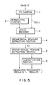
- FIG.4 is a conceptual block diagram to show the fundamental method of this invention measurement;
- FIG.5 is a flow chart to show the measurement and recognition principle according to this invention;
- FIG.6 is a chart to show the local displacement direction to compute Nth order autocorrelation;
- FIG.7 is a view to show local autocorrelation masks up to the second order:
- FIGs.8A, 8B and FIG.9 are views to show the local autocorrelation masks with hexagonal shapes up to the second order, respectively;
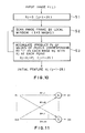
- FIG.10 is a flow chart to show an example of the operation for the basic initial feature extraction;
- FIG.11 is a chart to show a linear combination for the statistical feature extraction;
- FIG.12 is a flow chart to show the learning mode and the measuring recognition mode of the system;
- FIGs.20A to 20D are image views in number measurement of two type particles;
- FIGs.21A to 21D are image views in the measurement of topological characteristics; and
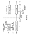
- FIG.13 is a block diagram to show an embodiment of this invention device;
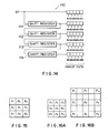
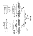
- FIG.14 is a detailed circuit to show partial image cutting-out circuit;
- FIG.15 and FIGs.16A and 16B are views to show examples thereof in output, respectively;
- FIG.17 is a block diagram to show the structure of an output section;
- FIG.18 is a circuit to show an embodiment of a window signal generating circuit;
- FIG.19 is a view to explain the coordinates of a window;
- FIGs.20A to 20D are image views in number measurement of two type particles;
- FIGs.21A to 21D are image views in the measurement of topological characteristics; and
- FIGs.22 through 25 are views to explain application of this invention to pattern recognition.
- Most of the problems encountered in practical image measurement are those of measuring the area or circumference of an object caught within the frame (or on a screen) of images, and the counting of the number of holes or the counting of the number of objects of a large number of the same groups on the screen. Problems of recognition to decide an object are also included in the measurement (such as those of shape measurement) problems in a broader sense. The measured results to the problems of those measurements of various images are generally given in the form of measured values (numeral values), and therefore the image measurement can be regarded as a problem for extracting the features from an image. The fundamental conditions to be met are as follows.
- ① Invariant to parallel displacement
- ② Additivity with respect to a screen (an image frame)
- ③ Adaptive learning possibility
- Feature extraction comprising the following two stages F1 and F2 is proposed in order to satisfy the above fundamental three
conditions ① to ③. - F1: A large number of general and basic features which satisfy the
above conditions - F2: New features which are optimized to various applications are adaptively extracted through the learning by means of linearly combining the above-mentioned initial features (Statistical characteristic extraction).
- For the geometrical feature extraction of the stage F1, for instance, we can use the feature extraction by local autocorrelation masks based on the principle of autocorrelation of Nth order (refer to U.S. Patent 4,288,779 corresponding to Japanese Patent Publication No.47064/1983). The statistical feature extraction of the stage F2 can be realized by the technique of linear regression analysis or the like in multivariate analysis. The linear combination in the statistical feature extraction F2 is necessary to maintain the above condition to show the learning mode and the measuring recognition mode of the system.
- The measuring concept of this invention, as shown in FIG.5, based on the feature extractions in the above two stages of F1 and F2 is a parallel and adaptive measuring method which can satisfy the
fundamental conditions ① through ③, and is simple in structure and easy to implement. The measuring method enables the image measurement adaptive to various and many uses by the high speed learning. - The measuring device according to this invention measures the images of the two-dimensional patterns universally and rapidly in real time based on the aforementioned operation.
- The measuring principle of this invention will now be described referring to attached drawings.
- An object of measurement as shown in FIG.5 is expressed as gray scale (multi-values) within a frame through a TV camera (for instance, CCD) 1. Although this measuring method is applicable to the gray scale (signal SG1) as it is, it is applied here to binary images which are binarized by a
binarizing circuit 2 for facilitating the explanation since the objects for the measurement are mostly the binary images in practice. The gray scale is binarized by a predetermined threshold value and divided into object areas (value 1: black) and background areas (value 0: white), and are inputted into an image memory (M× M pixels) 3. - A geometrical
feature extraction section 4 extracts the initial features for an image f(r) (wherein r = (i,j) is a two-dimensional vector representing its position on the screen) caught within the image frame (on theimage memory 3; hereinafter referred to simply as on the screen). The features to be extracted are specifically the autocorrelation functions of Nth order shown below (refer to U.S. Patent 4,288,779. Labers underlined hereinbelow represent vectors.
- The extraction of the initial features is based on the principle of the above formula (1). In other words, the extraction of the initial features represents positional unchangeability or invariance with regard to any parallel displacement therein f(r)→ f (r + b) within the image frame of the object. Although the displacement direction (a₁, ......, a N) may be arbitrarilly determined, it would suffice for practical purposes if N is limited to the order of two and the displacement direction is limited to the directions of the
locality 3× 3 around a reference point r in order to satisfy theabove condition ②. FIG.6 shows an example of the local displacement direction. In this case, the Nth order autocorrelation function of the above formula (1) can be calculated by scanning once the whole screen with a local frame (with the center r) of 3×3. In the case of the binary images, this procedure means none other than the procedure of counting the number of times the expression holds as f(r) f(r + a₁) ...... f(r + aN) = 1 or the local patterns in a whole image where all the pixels (N + 1) of the functions in thelocal frames 3×3 become to "1". The such local patterns on a (N + 1) pixel point apparently exist in the number (in the case of up to the 2nd degree, N = 0,1,2) of combination which allows the (N + 1) point to be selected from thenumber 3×3 = 9. When we take the scanning into consideration, however, the patterns translatable in parallel displacement within the local frame are equivalent to each other, and the number of independent patterns up to the 2nd order ultimately becomes "25" as shown in FIG.7. In the patterns in FIG.7, "1" represents pixels to be examined while "*" represents those to be ignored. These twenty-five patterns are called local autocorrelation masks. By scanning a whole screen once with these masks Mj (j = 1 through 25) and obtaining respective sums of products, twenty-five local autocorrelation coefficients xj are obtained as the initial features. The procedure of calculatiton is shown in the Steps S1 through S3 in FIG.10. U.S. Patent 4,288,779 corresponding to Japanese Patent Publication No.47064/1983 discloses the details of the calculating circuit method. Mask patterns are not limited the same shown in FIG.6, and they may be hexagonal patterns. The mask pattern may be hexagonal as shown in FIG.8A or 8D instead of the square of the size 3B ×3 as shown in FIG.7. The correlation using such a hexagonal pattern is effective in that fluctuation of intervals between the pixels from the center pixel is smaller than those with square pattern, that the number of the independent patterns can be reduced to "13" due to the invariance of parallel displacement, and that efficienct is higher compared to the case shown in FIG.7. In practical construction, the phases of the clock signal may be deviated by 180 degrees for each scanning line. FIG.9 shows a case of the autocorrelation mask (No.1 through No.17) which is independent in terms of the invariance of parallel displacement in the hexagonal patterns. The "1" and "*" within the patterns are similar to those shown in FIG.7. - The initial features xj from the geometrical
feature extraction section 4 are inputted to the statisticalfeature extraction section 5 as shown in FIG.5. Description will now be given to the statistical feature extraction (F2). - The initial features xj obtained as above are the features which are general and fundamental and which are not dependent on measurement problems. However, they cover the information of an objective image necessary for a measurement problem. Therefore, from these linear combina tions, in the structure as shown in FIG.11, and in accordance with the following formula (2), new features (measurement values themselves or forecast approximate values) effective to the measurement problem can be obtained as yi.

The letter M represents the number of the feature values which are simultaneously measured. The above formula (2) can be simplified as the following formula (2′) if the initial features xj and the new features yi are sorted in the vertical vector x = (x₁,......, x₂₅)′ and y = (y₁, ....... , yn)′ and a coefficient matrix A = [aij]′ is used (wherein"′" represents a transposition).
y = A′x (2′)
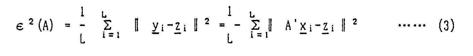
The coefficient A may be obtained trivially depending on problems. For example, the coefficient A is apparently obtained as y₁ = x₁ when the task is to count the area of a measuring object caught by the binary image, because the pixel number of the object is given by the autocorrelation coefficient x₁ with the mask M₁ the 0th order. By logical observation, other measuring values may be represented in a linear combination. However, these artificial methods are too complicated to be popularly used. This invention method therefore tries to obtain an optimal coefficient A automatically through the learning by means of a multivariate analysis method as shown in FIG.12. - Multiple regression analysis which is one of the multivariate analysis methods is an effective and direct method especially suitable for the measurement problems. It is assumed herein that a set of objective images to be used in the learning is denoted as G = {fi (r)} (provided i = 1 through L), a correct measurement vector for the image fi as z i, and the initial feature vector calculated at the Step S10 as x i (therefore the outputis y i = A′xi). The optimal coefficient A is obtained so as to minimize the following means square error (3) at the Step S12, and the optimal solution is explicitly given by the formula (4).
The following formula (5) represents an autocorrelation matrix with respect to the initial features x i and a crosscorrelation matrix with respect to the input data x i and z i, respectively. To the power of "-1" herein represents an inverse matrix.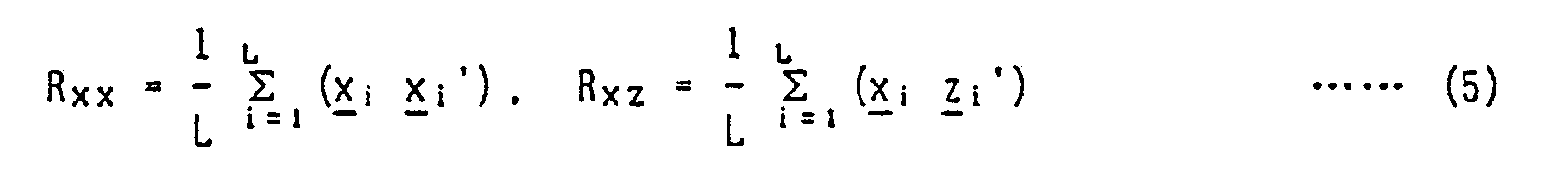
- The system in FIG.5 can hereafter estimate quite accurately the measurement vector for an input image f(r) in the running mode (Right half of FIG.12) by using the coefficient A obtained at the Steps S11 and S12 in the learning mode (Left half of FIG.12). If the accurate measurement vector z i can be expressed by the above formula (2), a correct coefficient A is automatically obtained by the learning.
- Recognition of objects may be possible in a similar manner. In the case of the multiple regression analysis, it can be solved by considering the measurement vectors (z i and y) as codes differentiating the classes of the objects to be recognized, and doing the similar learning. For instance, when the objects comprising two classes, the coefficient A is learned in the learning mode for the class "1" as z = (1, 0)′ and for the class "2" as z = (0, 1)′. In the measuring (recognition) mode, a
classification section 6 in FIG.5 compares the feature y₁ with another feature y₂ for y = (y₁,y₂)′ obtained for an input objective image (Step S22), and if y₁ is greater than y₂, it judges that is class"1", and if it is smaller, it judges that is class "2". If the classes are in a large number (K), similar operation can classify them.
Accordingly, in the mode of the recognition, a processing for the classification such as detection of the maximum value of the feature yi becomes necessary. - Discriminant analysis may be used as the learning of the coefficient A for recognition. In this case, the coefficient A can be obtained as a solution (eigenvectors) of an eigenvalue problem below in a manner to optimally separate (discriminate) K classes in the space of the vector y.
XBA = XWA Λ (A′XWA = I) (6)
wherein the letter Λ denotes diagonal eigenvalue matrix, and I denotes the unit matrix. Further, the letters XW and XB denote respectively the within-class covariance matrix and the between-class covariant matrix of the initial feature vector x, and are defined by the following formula.


- The image measuring device according to this invention is based on the aforementioned principle, and an embodiment will now be described referred to FIG.13.
- An
industrial TV camera 101 picks up anobjective image 100, and sequentially outputs two-dimensional video images IS in time series to asampling circuit 102 and an output image synthesizing/switching circuit 154. Thesampling circuit 102 converts the video images IS sequentially into digital values (herein binary values) BP in accordane with a clock signal CLK fed from a timingsignal generating circuit 103. The clock signal CLK is of about 6 MHz if the whole screen is assumed to have 320-pixels horizontally and 240-pixels vertically. The binary images BP from thesampling circuit 102 are inputted to the output image synthesizing/switching circuit 154 and a partial image cutting-outcircuit 110 to be shown in more detail in FIG.14. In the partial image cutting-outcircuit 110, the binary images BP in serial time are converted into parallel image data a₁₁ through a₅₅ of 5×5 = 25 pixels when they are inputted to shiftregisters 111 through 114 which delay images by one horizontal line. Nine pixels are selected from the parallel image data a₁₁ through a₅₅. If it is assumed that pixels for outputs are P₁ through P₉ in FIG.15 as listed in Table 1, nine pixels in a square shape of 3×3 size as shown in FIG.16A or nine pixels in a square shape of 5×5 size as shown in FIG.16B will be outputted. The relationship between the mask patterns and the objective image may be modified size-wise in similar figures. The size may easily be increased to 7×7 or 9×9 simply by adding other circuits. By preparing plural sets of the mask patterns, parallel and simultaneous processing becomes possible. These functions enable the extraction of the features with an appropriately sized mask pattern adaptively to the size of the objective pattern but without the necessity of changing the magnification of the pick-up lens system.Table 1 input A input B output a₁₁ a₂₂ P₁ a₁₃ a₂₃ P₂ a₁₅ a₂₄ P₃ a₃₁ a₃₂ P₄ a₃₃ a₃₃ P₅ a₃₅ a₃₄ P₆ a₅₁ a₄₂ P₇ a₅₃ a₄₃ P₈ a₅₅ a₄₄ P₉ - The pixels may be selected with a selection signal SL from a controlling section comprising a
CPU 150 and so on by, for instance, amultiplexer 115 as shown in FIG.17. For example, either one of the pixels a₁₁ and a₂₂ is selected and then outputted. - The video images DP thus cut-out are inputted to a
matching circuit 120 within a correlatingcircuit 160, and correlated to an autocorrelation mask as it is unchanged by the parallel displacement. Thematching circuit 120 matches them within the scope of a window signal WS generated by a windowsignal generating circuit 140. Description will be first given to the windowsignal generating circuit 140. The windowsignal generating circuit 140 is structured as shown in FIG.18. For simplicity's sake, the explanation is made in respect of a case where a circuit is structured to process the hatched portion (or window) out of the video signals as shown in FIG.19. The circuit inputs horizontal synchronizing signals HD, vertical synchronizing signals VD and the clock signal CLK from the timingsignal generating circuit 103, and counters 141 and 145 generate X-coordinates XS and Y-coordinates YS. In other words, thecounter 141 counts the clock signal CLK using the horizontal synchronizing signals HD as a clear signal while thecounter 145 counts the horizontal synchronizing signals HD using the vertical synchronizing signals VD as a clear signal. The output XS from thecounter 141 and the output YS from thecounter 145 are compared bydigital comparators circuits circuit 149 outputs the window signal WS. In other words, the window signal WS is outputted in a manner so that when the output XS from thecounter 141 exists between the set values X₁ and X₂₁ the output AN1 from the ANDcircuit 144 becomes "1", when the output YS from thecounter 145 exists between the set values Y₁ and Y₂, the output AN2 from the ANDcircuit 148 becomes "1", and when the both of the outputs AN1 and AN2 are "1", the output from the ANDcircuit 149 becomes "1". Therefore, when the output exists within the hatched portion in FIG. 19, the window signal WS becomes "1". The window signal WS is inputted to thematching circuit 120 to designate the scope of matching and the output image synthesizing/switching circuit 154. Correlation histogram is counted only when the window signal WS is "1" (or possibly "0") . The end of this window signal WS becomes a sign to finish the counting operation. The window signal WS is effective since it can process only the objects, cut out in accordance with the size of the object, and sequentially scan a screen at an arbitrary interval. - The
matching circuit 120 conducts matching operation with the autocorrelation mask as shown in FIG.7 by obtaining logical products of the portion of "1" in the figure. If the image is of multivalues, the sum of the portions of "1" will suffice. - The correlation data CL matched by the
matching circuit 120 are inputted to the counting means 130 comprising plural counters in the number equivalent to the autocorrelation masks, and outputs thereof are then sequentially counted by the plural counters. The counted data are stored in anRAM 152 and may be read out at any time. Then, the data of the counting means 130 are initialized by the horizontal and vertical synchronizing signals from the timingsignal generating circuit 103. - The output image synthesizing/
switching circuit 154 switches the video images IS from theTV camera 101 and the binary images BP with the switching signal PS from theCPU 150 to display, and displays the window signal WS when the need arises. TheCPU 150 makes necessary setting at thesampling circuit 102, the partial image cutting-outcircuit 110 and the counting means 130 in accordance with the program stored in theROM 151, conducts the learning and the arithmetic operations, and does the measurement and output. TheCPU 150 is connected with such input devices as a keyboard via an input/output interface 153 so that it can input the teaching data, direct the learning sampling, output the results and input for directly various settings. For instance, the size (5 ×5 or 3×3) to be cut out of images is controlled in a way since the mask pattern No.1 represents the area (size) of an object pattern, if this value is greater than a predetermined value, thesize 5 ×5 will be chosen while if it is less than the value, thesize 3 ×3 will be chosen. - In these constructions, the
object 100 which has been picked up by theTV camera 101 is extracted of the features in the form of 25-demensional vector or initial features xj as a matching histogram (counted values) with the mask patterns. Only the space within the window becomes the object of measurement, and the initial features xj are extracted every time the window signal WS ends. In the process of the learning, the initial features xj are stored in theRAM 152 together with the information teached in accordance with plural commands. In the process of the arithmetic analysis, the plural data within the memory are processed with the technique of the multivariate analysis so as to determine the parameters for the subsequent measurements. In the process of the measurement, with these parameters, the initial features xj extractedfrom unknown object are judged to output the result of the measurement. - Concrete embodiments in which this invention method is applied to various uses will be explained hereinafter. The binary image is considered and an example in a case that multiple regression analysis is used as the statistical feature extraction by an adaptive learning is explained, and the case of discriminant analysis is omitted.
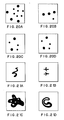
- First, the result of applying the method to a problem to simultaneously measure the number of two circles (particles) in an image frame which have different diameters is explained. Fourty images including two type circles in random are prepared and the examples are shown in FIGs. 20A to 20D. The image in FIG.20D shows a real binarized image which is inputted to a system through a TV camera for the image in FIG.20C and the image in FIG.20D is seen to be greatly influenced with noises. The learning is performed by using the above images. In this case, the teaching input to the respective images is two-dimensional vector of z = (z₁, z₂)′, the letter z₁ is number of larger circles and the letter z₂ is number of smaller circles. The most suitable coefficient matrix A (25×2) is obtained by the learning and the measurement (estimation) to the inputted image is performed by y = (y₁, Y₂)′ of the formula (2′) used the coefficient matrix A. For example, the measurement to the image in FIG.20A was (y₁, y₂) = (4.10, 5.88), the image in FIG.20B (y₁, y₂) = (3,09. 0.88) and the image in FIG.20C (y₁, y₂) = (1.97, 3.02). It is possible to obtain good results while the images are in noises (Right number is realy obtained by round with a margin).
- Next, measurement examples of topological characteristic of the objective image are shown in FIGs.21A to 21D. For example, the examples are numbers of the objects separated in the image frame (FIGs.21A and 21B) and are numbers of holes of the objects (FIGs.21C and 21D). It is an important matter as the topological characteristics that the number is irrespective of the shapes of the objects or the holes. For the forty-eight images including the various objects separated, the learning is performed as the teaching inputs z₁ of the right number. FIGs.21A and 21B are examples of the images which are used in the above examples. As a result, the system rightly measure the number of separated objects for the inputted images which are optionally given. The value y₁ was respectively "1, 2" for FIGs.21A and 21B. The measurement of the hole number also could obtain very good results. The value y₁ was respectively "5, 1" for FIGs.21C and 21D.
- The above measurement principle proves that Euler's formula in topology is substantially approximated with models. What is most significant herein is the system according to this invention method automatically learns the Euler's formula (instead of being tought as a program).
- The application to the recognition is explained. The objects are generated "84" numbers in triangle of optional shape and are respetively allotted to the learning images. The recognition problem discriminates which is acute or obtuse angle and the teaching inputs were (z₁, z₂) = (0, 1) for the obtuse angle triangles and (z₁, z₂) = (1, 0) for the acute angle triangles. When the 84-images are recognized by using the most suitable coefficient matrix A, only one was missed the acute angle as the obtuse angle. The missed triangle was almost a rectangular triangle.
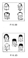
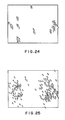
- An example of practial application of the aforementioned image measuring device will now be described hereinbelow. The device may be applied to a system which discriminates faces wearing glasses as shown in FIG.22 from faces without glasses as shown in FIG.23. The system first shows the faces with glasses in FIG.22, then sets windows to include one face in each, indicates classes (in other words whether or not the face wears a pair of glasses) and samples them. Sampling data comprises 25-dimensional vectors and classes (i .e. "1" or "2"). These faces are inputted in a manner to allow slight disturbance (e.g. giving a minute angular displacement for 10 times). The similar operation is conducted for the faces without glasses shown in FIG.23. This makes the ninety initial features x stored in the
RAM 152, and the learning process ended. TheCPU 150 does the discriminant analysis in its arithmetic operation to xtract the statistical features optimal to decide the faces with glasses from the faces without glasses. While in FIG.24 the data of the faces form lumps randomly withclass 1 andclass 2 mixed, in FIG.25 (after the discriminant analysis) the twoclasses class 1. - It is possible to measure images at very high speed and in real time by performing the most suitable statistical feature extraction adaptive to the respective measurement problems obtained by the learning from the common initial features obtained by the once scanning of the image frame without consideration of the cutting, while the conventional method cuts the objective region from the image frame and sequentially applies specific image processing and feature extraction. Moreover, important matter is that the processing time is constant irrespective of the measurment problems. For example, in a case of particle measurement, the measurement time for "1000" particles is equal to the same for "1". Further, according to this invention, it is easy to rrealize the device since the structure is simple and essentially parallel calculation.
- It is possible to apply the same device to various usages by the adaptive learning, and the device has high generality, and the learning due to the multivariate analysis is simple and high speed. Especially, it does not need to give an algorithm how to measure and it is sufficient to show an images to simply become examples and answers (measuring values to be obtained) for those. In this connection, it is possible to apply the invention to the problem which is impossible by the prior art sequential method and measurement algorithm is unknown. Further, since the position is invariable, it is possible to measure moving images (objects sequentially moving in time, for example, parts on the belt-conveyor). Therefore, the present method has good effects as a cheap general purpose image measuring device.
- Further, the feature extraction according to this invention has good effciency and universal character, and therefore it is possible to link to neuro-computers, especially multilayered feed-forward neural networks with an error back propagation learning. For example, in a case of inputting letters (images) of 32 ×32, it needs input layers of 1024 if the input for pizels thereof is directly performed. On the contrary, the number of the input is 13 to 25 if the output of the local autocorrelation mask according to this invention is used. In this connection, the structure of the neuro-computer may be small. The efficiency becomes great if the object image is large. Fyrther, since the system does not need position-invariant learning and can efficiently learn, the learning time becomes short. The neuro-computer is described in "Parallel Distributed Processing", Vol. I , II, MIT Press, 1986, by D.E.Rumelhart, J.L.Mcclellard and the PDP Research Group.
- As described above, according to this invention measurement and recognition device, users of the device can learn the device about the objects they wish to measure, to thereby allow the device automatically to select the optimum measurement method under the particular situation and to measure them at a higher speed. Terefore, this invention device can be applied to any uses no matter how difficult it is to determine an optimal means for discrimination. Further, the device performs the measurement at high resistance against the disturbance at the site as it can learn about surrounding environment. The device is not only adaptive but also easy to use as it can provide the extraction of the feature effectively and adaptively by such functions as windows and mask size switching. The device can perform a high speed processing in real time due to parallel calculation irrespective of the position of a particular object with a window. Since it is of the type of the adaptive learning, the same device can be applied to various purposes and thus is of universal type. The device does not have to be fed with any algorithm, but can measure if users simply provide example images and corresponding answers (or measurement values to obtain).
- It should be understood that many modifications and adaptations of the invention will become apparent to those skilled in the art and it is intended to encompass such obvious modifications and changes in the scope of the claims appended hereto.
Claims (16)
Applications Claiming Priority (4)
| Application Number | Priority Date | Filing Date | Title |
|---|---|---|---|
| JP255678/88 | 1988-10-11 | ||
| JP63255678A JP2982814B2 (en) | 1988-10-11 | 1988-10-11 | Adaptive learning type general-purpose image measurement method |
| JP63255679A JP2834153B2 (en) | 1988-10-11 | 1988-10-11 | Adaptive learning type general purpose image measurement device |
| JP255679/88 | 1988-10-11 |
Publications (3)
| Publication Number | Publication Date |
|---|---|
| EP0363828A2 true EP0363828A2 (en) | 1990-04-18 |
| EP0363828A3 EP0363828A3 (en) | 1992-08-12 |
| EP0363828B1 EP0363828B1 (en) | 1999-01-07 |
Family
ID=26542362
Family Applications (1)
| Application Number | Title | Priority Date | Filing Date |
|---|---|---|---|
| EP89118529A Expired - Lifetime EP0363828B1 (en) | 1988-10-11 | 1989-10-05 | Method and apparatus for adaptive learning type general purpose image measurement and recognition |
Country Status (3)
| Country | Link |
|---|---|
| US (2) | US5442716A (en) |
| EP (1) | EP0363828B1 (en) |
| DE (1) | DE68928895T2 (en) |
Cited By (3)
| Publication number | Priority date | Publication date | Assignee | Title |
|---|---|---|---|---|
| CN101030244B (en) * | 2006-03-03 | 2010-08-18 | 中国科学院自动化研究所 | Automatic identity discriminating method based on human-body physiological image sequencing estimating characteristic |
| US7957560B2 (en) | 2006-06-16 | 2011-06-07 | National Institute Of Advanced Industrial Science And Technology | Unusual action detector and abnormal action detecting method |
| US7957557B2 (en) | 2004-12-02 | 2011-06-07 | National Institute Of Advanced Industrial Science And Technology | Tracking apparatus and tracking method |
Families Citing this family (33)
| Publication number | Priority date | Publication date | Assignee | Title |
|---|---|---|---|---|
| US5740270A (en) * | 1988-04-08 | 1998-04-14 | Neuromedical Systems, Inc. | Automated cytological specimen classification system and method |
| EP0590759B1 (en) * | 1992-08-12 | 1998-12-09 | International Business Machines Corporation | System and method for locating video segment boundaries |
| JPH06169395A (en) * | 1992-11-27 | 1994-06-14 | Sharp Corp | Image forming device |
| DE59403318D1 (en) * | 1993-04-10 | 1997-08-14 | Fraunhofer Ges Forschung | PROCESS FOR CLASSIFYING OBJECTS |
| JP3549569B2 (en) * | 1993-04-27 | 2004-08-04 | ソニー エレクトロニクス インコーポレイテッド | Target pattern detection method in video |
| US5911035A (en) * | 1995-04-12 | 1999-06-08 | Tsao; Thomas | Method and apparatus for determining binocular affine disparity and affine invariant distance between two image patterns |
| JP4114959B2 (en) * | 1995-06-20 | 2008-07-09 | キヤノン株式会社 | Image processing method and apparatus |
| US5768421A (en) * | 1995-09-12 | 1998-06-16 | Gaffin; Arthur Zay | Visual imaging system and method |
| US6625317B1 (en) | 1995-09-12 | 2003-09-23 | Art Gaffin | Visual imaging system and method |
| US6996549B2 (en) * | 1998-05-01 | 2006-02-07 | Health Discovery Corporation | Computer-aided image analysis |
| US6452177B1 (en) | 1998-09-04 | 2002-09-17 | California Institute Of Technology | Atmospheric electron x-ray spectrometer |
| JP4209201B2 (en) * | 2001-05-01 | 2009-01-14 | フィリップス エレクトロニクス ノース アメリカ コーポレイション | Image processing apparatus and image processing method |
| US6629010B2 (en) | 2001-05-18 | 2003-09-30 | Advanced Vision Particle Measurement, Inc. | Control feedback system and method for bulk material industrial processes using automated object or particle analysis |
| US6885904B2 (en) * | 2001-05-18 | 2005-04-26 | Advanced Vision Particle Measurement, Inc. | Control feedback system and method for bulk material industrial processes using automated object or particle analysis |
| GB2382289B (en) * | 2001-09-28 | 2005-07-06 | Canon Kk | Method and apparatus for generating models of individuals |
| WO2004039531A2 (en) * | 2002-10-31 | 2004-05-13 | Ehsan Toyserkani | System and method for closed-loop control of laser cladding by powder injection |
| US7375731B2 (en) * | 2002-11-01 | 2008-05-20 | Mitsubishi Electric Research Laboratories, Inc. | Video mining using unsupervised clustering of video content |
| JP3987013B2 (en) * | 2003-09-01 | 2007-10-03 | 本田技研工業株式会社 | Vehicle periphery monitoring device |
| EP1751628A4 (en) * | 2004-05-20 | 2007-12-05 | Univ Mcmaster | Method for controlling the appearance of products and process performance by image analysis |
| JP4368767B2 (en) * | 2004-09-08 | 2009-11-18 | 独立行政法人産業技術総合研究所 | Abnormal operation detection device and abnormal operation detection method |
| US7583819B2 (en) * | 2004-11-05 | 2009-09-01 | Kyprianos Papademetriou | Digital signal processing methods, systems and computer program products that identify threshold positions and values |
| JP4603512B2 (en) * | 2006-06-16 | 2010-12-22 | 独立行政法人産業技術総合研究所 | Abnormal region detection apparatus and abnormal region detection method |
| JP4429298B2 (en) * | 2006-08-17 | 2010-03-10 | 独立行政法人産業技術総合研究所 | Object number detection device and object number detection method |
| US7849037B2 (en) * | 2006-10-09 | 2010-12-07 | Brooks Roger K | Method for using the fundamental homotopy group in assessing the similarity of sets of data |
| US7849039B2 (en) * | 2006-12-29 | 2010-12-07 | Brooks Roger K | Method for using one-dimensional dynamics in assessing the similarity of sets of data using kinetic energy |
| US7849038B2 (en) * | 2006-12-31 | 2010-12-07 | Brooks Roger K | Method for using the second homotopy group in assessing the similarity of sets of data |
| US8644600B2 (en) * | 2007-06-05 | 2014-02-04 | Microsoft Corporation | Learning object cutout from a single example |
| US7876421B2 (en) * | 2008-01-29 | 2011-01-25 | Ian Lewin | Light meter apparatus and system |
| US8786847B2 (en) | 2011-01-12 | 2014-07-22 | Underwriters Laboratories, Inc. | Light measuring meter apparatus |
| CN102523482B (en) * | 2011-12-07 | 2014-07-23 | 中山大学 | Advertisement monitoring technology based on video content and regression method |
| CA2952576C (en) | 2014-06-20 | 2022-07-26 | Miovision Technologies Incorporated | Machine learning platform for performing large scale data analytics |
| US10083530B1 (en) * | 2016-10-21 | 2018-09-25 | The United States Of America As Represented By The Secretary Of The Army | Multivariate digital display device and method for increasing the separation between classes' data points in hyperspace |
| US10747989B2 (en) * | 2018-08-21 | 2020-08-18 | Software Ag | Systems and/or methods for accelerating facial feature vector matching with supervised machine learning |
Citations (2)
| Publication number | Priority date | Publication date | Assignee | Title |
|---|---|---|---|---|
| US3267431A (en) * | 1963-04-29 | 1966-08-16 | Ibm | Adaptive computing system capable of being trained to recognize patterns |
| US4288779A (en) * | 1978-07-08 | 1981-09-08 | Agency Of Industrial Science & Technology | Method and apparatus for character reading |
Family Cites Families (8)
| Publication number | Priority date | Publication date | Assignee | Title |
|---|---|---|---|---|
| US3588823A (en) * | 1968-03-28 | 1971-06-28 | Ibm | Mutual information derived tree structure in an adaptive pattern recognition system |
| US3968475A (en) * | 1974-11-11 | 1976-07-06 | Sperry Rand Corporation | Digital processor for extracting data from a binary image |
| US4177448A (en) * | 1978-06-26 | 1979-12-04 | International Business Machines Corporation | Character recognition system and method multi-bit curve vector processing |
| US4760604A (en) * | 1985-02-15 | 1988-07-26 | Nestor, Inc. | Parallel, multi-unit, adaptive, nonlinear pattern class separator and identifier |
| US4805225A (en) * | 1986-11-06 | 1989-02-14 | The Research Foundation Of The State University Of New York | Pattern recognition method and apparatus |
| US4965725B1 (en) * | 1988-04-08 | 1996-05-07 | Neuromedical Systems Inc | Neural network based automated cytological specimen classification system and method |
| US5048100A (en) * | 1988-12-15 | 1991-09-10 | Michael Kuperstein | Self organizing neural network method and system for general classification of patterns |
| US4954963A (en) * | 1989-03-02 | 1990-09-04 | Texas Instruments Incorporated | Neural network and system |
-
1989
- 1989-10-05 DE DE68928895T patent/DE68928895T2/en not_active Expired - Fee Related
- 1989-10-05 EP EP89118529A patent/EP0363828B1/en not_active Expired - Lifetime
-
1993
- 1993-06-24 US US08/080,976 patent/US5442716A/en not_active Expired - Lifetime
-
1994
- 1994-12-05 US US08/353,323 patent/US5619589A/en not_active Expired - Lifetime
Patent Citations (2)
| Publication number | Priority date | Publication date | Assignee | Title |
|---|---|---|---|---|
| US3267431A (en) * | 1963-04-29 | 1966-08-16 | Ibm | Adaptive computing system capable of being trained to recognize patterns |
| US4288779A (en) * | 1978-07-08 | 1981-09-08 | Agency Of Industrial Science & Technology | Method and apparatus for character reading |
Non-Patent Citations (4)
| Title |
|---|
| 632; A. KHOTANZAD ET AL.: 'Distortion invariant character recognition by a multi-layer perceptron and back-propagation learning' * |
| IEEE INTERN. CONF. ON NEURAL NETWORKS 24 July 1988, SAN DIEGO, US pages 625 - 632; A. KHOTANZAD ET AL.: 'Distortion invariant character recognition by a multi-layer perceptron and back-propagation learning' * |
| PATTERN RECOGNITION. vol. 16, no. 6, 1983, ELMSFORD, NY, US pages 593 - 603; S QING-YUN ET AL.: 'A method for the design of binary tree classifiers' * |
| PROC. OF THE 1987 IEEE INTERN. CONF. ON SYSTEMS, MAN, AND CYBERNETICS 20 October 1987, ALEXANDRIA, US pages 724 - 729; S. HINDS: 'Organization based on pattern learning and recognition' * |
Cited By (3)
| Publication number | Priority date | Publication date | Assignee | Title |
|---|---|---|---|---|
| US7957557B2 (en) | 2004-12-02 | 2011-06-07 | National Institute Of Advanced Industrial Science And Technology | Tracking apparatus and tracking method |
| CN101030244B (en) * | 2006-03-03 | 2010-08-18 | 中国科学院自动化研究所 | Automatic identity discriminating method based on human-body physiological image sequencing estimating characteristic |
| US7957560B2 (en) | 2006-06-16 | 2011-06-07 | National Institute Of Advanced Industrial Science And Technology | Unusual action detector and abnormal action detecting method |
Also Published As
| Publication number | Publication date |
|---|---|
| DE68928895D1 (en) | 1999-02-18 |
| EP0363828A3 (en) | 1992-08-12 |
| DE68928895T2 (en) | 1999-05-27 |
| EP0363828B1 (en) | 1999-01-07 |
| US5619589A (en) | 1997-04-08 |
| US5442716A (en) | 1995-08-15 |
Similar Documents
| Publication | Publication Date | Title |
|---|---|---|
| EP0363828A2 (en) | Method and apparatus for adaptive learning type general purpose image measurement and recognition | |
| Kuzmanic et al. | Hand shape classification using DTW and LCSS as similarity measures for vision-based gesture recognition system | |
| Espinal et al. | Wavelet-based fractal signature analysis for automatic target recognition | |
| CN102722712A (en) | Multiple-scale high-resolution image object detection method based on continuity | |
| CN110751097B (en) | Semi-supervised three-dimensional point cloud gesture key point detection method | |
| JP2010134957A (en) | Pattern recognition method | |
| CN111539330B (en) | Transformer substation digital display instrument identification method based on double-SVM multi-classifier | |
| CN106529441B (en) | Depth motion figure Human bodys' response method based on smeared out boundary fragment | |
| CN111914643A (en) | Human body action recognition method based on skeleton key point detection | |
| CN112132117A (en) | Fusion identity authentication system assisting coercion detection | |
| Zhang | Application of artificial intelligence recognition technology in digital image processing | |
| CN114283326A (en) | Underwater target re-identification method combining local perception and high-order feature reconstruction | |
| Minami et al. | Robust scene recognition using a GA and real-world raw-image | |
| CN116703895B (en) | Small sample 3D visual detection method and system based on generation countermeasure network | |
| CN114065798A (en) | Visual identification method and device based on machine identification | |
| CN117437691A (en) | Real-time multi-person abnormal behavior identification method and system based on lightweight network | |
| CN109800771B (en) | Spontaneous micro-expression positioning method of local binary pattern of mixed space-time plane | |
| JP2982814B2 (en) | Adaptive learning type general-purpose image measurement method | |
| Miciak | Character recognition using Radon transformation and principal component analysis in postal applications | |
| CN111292346A (en) | Method for detecting contour of casting box body in noise environment | |
| CN116912670A (en) | Deep sea fish identification method based on improved YOLO model | |
| JP2834153B2 (en) | Adaptive learning type general purpose image measurement device | |
| CN110751189B (en) | Ellipse detection method based on perception contrast and feature selection | |
| CN117152083B (en) | Ground penetrating radar road disease image prediction visualization method based on category activation mapping | |
| CN111291624B (en) | Excavator target identification method and system |
Legal Events
| Date | Code | Title | Description |
|---|---|---|---|
| PUAI | Public reference made under article 153(3) epc to a published international application that has entered the european phase |
Free format text: ORIGINAL CODE: 0009012 |
|
| AK | Designated contracting states |
Kind code of ref document: A2 Designated state(s): DE FR GB IT SE |
|
| 17P | Request for examination filed |
Effective date: 19911018 |
|
| PUAL | Search report despatched |
Free format text: ORIGINAL CODE: 0009013 |
|
| AK | Designated contracting states |
Kind code of ref document: A3 Designated state(s): DE FR GB IT SE |
|
| 17Q | First examination report despatched |
Effective date: 19940621 |
|
| GRAG | Despatch of communication of intention to grant |
Free format text: ORIGINAL CODE: EPIDOS AGRA |
|
| GRAG | Despatch of communication of intention to grant |
Free format text: ORIGINAL CODE: EPIDOS AGRA |
|
| GRAH | Despatch of communication of intention to grant a patent |
Free format text: ORIGINAL CODE: EPIDOS IGRA |
|
| RAP1 | Party data changed (applicant data changed or rights of an application transferred) |
Owner name: KABUSHIKI KAISHA OUYO KEISOKU KENKYUSHO Owner name: AGENCY OF INDUSTRIAL SCIENCE AND TECHNOLOGY |
|
| GRAH | Despatch of communication of intention to grant a patent |
Free format text: ORIGINAL CODE: EPIDOS IGRA |
|
| GRAA | (expected) grant |
Free format text: ORIGINAL CODE: 0009210 |
|
| AK | Designated contracting states |
Kind code of ref document: B1 Designated state(s): DE FR GB IT SE |
|
| PG25 | Lapsed in a contracting state [announced via postgrant information from national office to epo] |
Ref country code: SE Free format text: THE PATENT HAS BEEN ANNULLED BY A DECISION OF A NATIONAL AUTHORITY Effective date: 19990107 |
|
| REF | Corresponds to: |
Ref document number: 68928895 Country of ref document: DE Date of ref document: 19990218 |
|
| ITF | It: translation for a ep patent filed |
Owner name: PORTA CHECCACCI E BOTTI S.R.L. |
|
| ET | Fr: translation filed | ||
| PLBE | No opposition filed within time limit |
Free format text: ORIGINAL CODE: 0009261 |
|
| STAA | Information on the status of an ep patent application or granted ep patent |
Free format text: STATUS: NO OPPOSITION FILED WITHIN TIME LIMIT |
|
| 26N | No opposition filed | ||
| EUG | Se: european patent has lapsed |
Ref document number: 89118529.0 |
|
| PG25 | Lapsed in a contracting state [announced via postgrant information from national office to epo] |
Ref country code: FR Free format text: LAPSE BECAUSE OF NON-PAYMENT OF DUE FEES Effective date: 20000630 |
|
| REG | Reference to a national code |
Ref country code: FR Ref legal event code: ST |
|
| REG | Reference to a national code |
Ref country code: GB Ref legal event code: IF02 |
|
| REG | Reference to a national code |
Ref country code: GB Ref legal event code: 732E |
|
| PGFP | Annual fee paid to national office [announced via postgrant information from national office to epo] |
Ref country code: GB Payment date: 20050923 Year of fee payment: 17 |
|
| PG25 | Lapsed in a contracting state [announced via postgrant information from national office to epo] |
Ref country code: IT Free format text: LAPSE BECAUSE OF NON-PAYMENT OF DUE FEES;WARNING: LAPSES OF ITALIAN PATENTS WITH EFFECTIVE DATE BEFORE 2007 MAY HAVE OCCURRED AT ANY TIME BEFORE 2007. THE CORRECT EFFECTIVE DATE MAY BE DIFFERENT FROM THE ONE RECORDED. Effective date: 20051005 |
|
| PGFP | Annual fee paid to national office [announced via postgrant information from national office to epo] |
Ref country code: DE Payment date: 20051213 Year of fee payment: 17 |
|
| PG25 | Lapsed in a contracting state [announced via postgrant information from national office to epo] |
Ref country code: DE Free format text: LAPSE BECAUSE OF NON-PAYMENT OF DUE FEES Effective date: 20070501 |
|
| GBPC | Gb: european patent ceased through non-payment of renewal fee |
Effective date: 20061005 |
|
| PG25 | Lapsed in a contracting state [announced via postgrant information from national office to epo] |
Ref country code: GB Free format text: LAPSE BECAUSE OF NON-PAYMENT OF DUE FEES Effective date: 20061005 |