EP0363948A1 - Nozzle for injection-moulding machines - Google Patents
Nozzle for injection-moulding machines Download PDFInfo
- Publication number
- EP0363948A1 EP0363948A1 EP89118957A EP89118957A EP0363948A1 EP 0363948 A1 EP0363948 A1 EP 0363948A1 EP 89118957 A EP89118957 A EP 89118957A EP 89118957 A EP89118957 A EP 89118957A EP 0363948 A1 EP0363948 A1 EP 0363948A1
- Authority
- EP
- European Patent Office
- Prior art keywords
- nozzle
- mold
- bore
- injection molding
- hollow needle
- Prior art date
- Legal status (The legal status is an assumption and is not a legal conclusion. Google has not performed a legal analysis and makes no representation as to the accuracy of the status listed.)
- Granted
Links
Images

Classifications
-
- B—PERFORMING OPERATIONS; TRANSPORTING
- B29—WORKING OF PLASTICS; WORKING OF SUBSTANCES IN A PLASTIC STATE IN GENERAL
- B29C—SHAPING OR JOINING OF PLASTICS; SHAPING OF MATERIAL IN A PLASTIC STATE, NOT OTHERWISE PROVIDED FOR; AFTER-TREATMENT OF THE SHAPED PRODUCTS, e.g. REPAIRING
- B29C45/00—Injection moulding, i.e. forcing the required volume of moulding material through a nozzle into a closed mould; Apparatus therefor
- B29C45/17—Component parts, details or accessories; Auxiliary operations
- B29C45/20—Injection nozzles
-
- B—PERFORMING OPERATIONS; TRANSPORTING
- B29—WORKING OF PLASTICS; WORKING OF SUBSTANCES IN A PLASTIC STATE IN GENERAL
- B29C—SHAPING OR JOINING OF PLASTICS; SHAPING OF MATERIAL IN A PLASTIC STATE, NOT OTHERWISE PROVIDED FOR; AFTER-TREATMENT OF THE SHAPED PRODUCTS, e.g. REPAIRING
- B29C45/00—Injection moulding, i.e. forcing the required volume of moulding material through a nozzle into a closed mould; Apparatus therefor
- B29C45/17—Component parts, details or accessories; Auxiliary operations
- B29C45/1703—Introducing an auxiliary fluid into the mould
- B29C45/1704—Introducing an auxiliary fluid into the mould the fluid being introduced into the interior of the injected material which is still in a molten state, e.g. for producing hollow articles
-
- B—PERFORMING OPERATIONS; TRANSPORTING
- B29—WORKING OF PLASTICS; WORKING OF SUBSTANCES IN A PLASTIC STATE IN GENERAL
- B29C—SHAPING OR JOINING OF PLASTICS; SHAPING OF MATERIAL IN A PLASTIC STATE, NOT OTHERWISE PROVIDED FOR; AFTER-TREATMENT OF THE SHAPED PRODUCTS, e.g. REPAIRING
- B29C44/00—Shaping by internal pressure generated in the material, e.g. swelling or foaming ; Producing porous or cellular expanded plastics articles
- B29C44/02—Shaping by internal pressure generated in the material, e.g. swelling or foaming ; Producing porous or cellular expanded plastics articles for articles of definite length, i.e. discrete articles
- B29C44/04—Shaping by internal pressure generated in the material, e.g. swelling or foaming ; Producing porous or cellular expanded plastics articles for articles of definite length, i.e. discrete articles consisting of at least two parts of chemically or physically different materials, e.g. having different densities
- B29C44/0492—Devices for feeding the different materials
-
- B—PERFORMING OPERATIONS; TRANSPORTING
- B29—WORKING OF PLASTICS; WORKING OF SUBSTANCES IN A PLASTIC STATE IN GENERAL
- B29C—SHAPING OR JOINING OF PLASTICS; SHAPING OF MATERIAL IN A PLASTIC STATE, NOT OTHERWISE PROVIDED FOR; AFTER-TREATMENT OF THE SHAPED PRODUCTS, e.g. REPAIRING
- B29C44/00—Shaping by internal pressure generated in the material, e.g. swelling or foaming ; Producing porous or cellular expanded plastics articles
- B29C44/02—Shaping by internal pressure generated in the material, e.g. swelling or foaming ; Producing porous or cellular expanded plastics articles for articles of definite length, i.e. discrete articles
- B29C44/10—Applying counter-pressure during expanding
- B29C44/105—Applying counter-pressure during expanding the counterpressure being exerted by a fluid
-
- B—PERFORMING OPERATIONS; TRANSPORTING
- B29—WORKING OF PLASTICS; WORKING OF SUBSTANCES IN A PLASTIC STATE IN GENERAL
- B29C—SHAPING OR JOINING OF PLASTICS; SHAPING OF MATERIAL IN A PLASTIC STATE, NOT OTHERWISE PROVIDED FOR; AFTER-TREATMENT OF THE SHAPED PRODUCTS, e.g. REPAIRING
- B29C44/00—Shaping by internal pressure generated in the material, e.g. swelling or foaming ; Producing porous or cellular expanded plastics articles
- B29C44/34—Auxiliary operations
- B29C44/58—Moulds
- B29C44/581—Closure devices for pour holes
-
- B—PERFORMING OPERATIONS; TRANSPORTING
- B29—WORKING OF PLASTICS; WORKING OF SUBSTANCES IN A PLASTIC STATE IN GENERAL
- B29C—SHAPING OR JOINING OF PLASTICS; SHAPING OF MATERIAL IN A PLASTIC STATE, NOT OTHERWISE PROVIDED FOR; AFTER-TREATMENT OF THE SHAPED PRODUCTS, e.g. REPAIRING
- B29C45/00—Injection moulding, i.e. forcing the required volume of moulding material through a nozzle into a closed mould; Apparatus therefor
- B29C45/16—Making multilayered or multicoloured articles
-
- B—PERFORMING OPERATIONS; TRANSPORTING
- B29—WORKING OF PLASTICS; WORKING OF SUBSTANCES IN A PLASTIC STATE IN GENERAL
- B29C—SHAPING OR JOINING OF PLASTICS; SHAPING OF MATERIAL IN A PLASTIC STATE, NOT OTHERWISE PROVIDED FOR; AFTER-TREATMENT OF THE SHAPED PRODUCTS, e.g. REPAIRING
- B29C45/00—Injection moulding, i.e. forcing the required volume of moulding material through a nozzle into a closed mould; Apparatus therefor
- B29C45/17—Component parts, details or accessories; Auxiliary operations
- B29C45/1703—Introducing an auxiliary fluid into the mould
- B29C45/1734—Nozzles therefor
-
- B—PERFORMING OPERATIONS; TRANSPORTING
- B29—WORKING OF PLASTICS; WORKING OF SUBSTANCES IN A PLASTIC STATE IN GENERAL
- B29C—SHAPING OR JOINING OF PLASTICS; SHAPING OF MATERIAL IN A PLASTIC STATE, NOT OTHERWISE PROVIDED FOR; AFTER-TREATMENT OF THE SHAPED PRODUCTS, e.g. REPAIRING
- B29C45/00—Injection moulding, i.e. forcing the required volume of moulding material through a nozzle into a closed mould; Apparatus therefor
- B29C45/17—Component parts, details or accessories; Auxiliary operations
- B29C45/46—Means for plasticising or homogenising the moulding material or forcing it into the mould
- B29C45/56—Means for plasticising or homogenising the moulding material or forcing it into the mould using mould parts movable during or after injection, e.g. injection-compression moulding
-
- B—PERFORMING OPERATIONS; TRANSPORTING
- B29—WORKING OF PLASTICS; WORKING OF SUBSTANCES IN A PLASTIC STATE IN GENERAL
- B29C—SHAPING OR JOINING OF PLASTICS; SHAPING OF MATERIAL IN A PLASTIC STATE, NOT OTHERWISE PROVIDED FOR; AFTER-TREATMENT OF THE SHAPED PRODUCTS, e.g. REPAIRING
- B29C67/00—Shaping techniques not covered by groups B29C39/00 - B29C65/00, B29C70/00 or B29C73/00
- B29C67/004—Closing perforations or small holes, e.g. using additional moulding material
-
- B—PERFORMING OPERATIONS; TRANSPORTING
- B29—WORKING OF PLASTICS; WORKING OF SUBSTANCES IN A PLASTIC STATE IN GENERAL
- B29C—SHAPING OR JOINING OF PLASTICS; SHAPING OF MATERIAL IN A PLASTIC STATE, NOT OTHERWISE PROVIDED FOR; AFTER-TREATMENT OF THE SHAPED PRODUCTS, e.g. REPAIRING
- B29C45/00—Injection moulding, i.e. forcing the required volume of moulding material through a nozzle into a closed mould; Apparatus therefor
- B29C45/17—Component parts, details or accessories; Auxiliary operations
- B29C45/1703—Introducing an auxiliary fluid into the mould
- B29C45/1704—Introducing an auxiliary fluid into the mould the fluid being introduced into the interior of the injected material which is still in a molten state, e.g. for producing hollow articles
- B29C2045/1718—Introducing an auxiliary fluid into the mould the fluid being introduced into the interior of the injected material which is still in a molten state, e.g. for producing hollow articles sealing or closing the fluid injection opening
Definitions
- the invention relates to a nozzle for injection molding machines according to the features of the preamble of main claim 1.
- a generic nozzle is already known from DE-OS 21 06 546.
- This nozzle carries only a hollow needle of constant length, firmly connected with it, which, when the mold is closed, always extends to the plastic core of the plastic injected first by means of another nozzle, but always opens when the mold is opened after the plastic injected first is solidified or at least - if the second medium is a further plastic component - leaves a clear disturbance of the surface in the molded plastic article.
- two-component nozzles have a much more complicated design than nozzles for a single component of an injection molding system that processes multiple components simultaneously, so that it is in many cases easier and cheaper to maintain, an injection molding system for the simultaneous processing of multiple components with multiple nozzles for one component each to be injected instead of being equipped with a single multi-component nozzle.
- the object of the present invention is therefore to provide a nozzle for injection molding machines with which a second medium can be introduced into the interior of a first plastic melt that has already been partially or completely injected into an injection mold, this nozzle on the one hand with a minimal structural design the seamless closing of the passage opening for the second medium by the first plastic melt and, on the other hand - at least when the second medium is a pressurized gas or a pressurized liquid - allows the interior of the plastic article to be depressurized within the closed mold without an external opening of the plastic article.
- the invention solves this problem with the aid of the features of the characterizing part of main claim 1.
- the nozzle according to the invention has two concentrically arranged hollow needles in its mold-side outlet channel, both with respect to the wall of the outlet channel of the nozzle or a bore possibly flushing it up to the mold surface, and also with one another in the axial direction which can be displaced in a fitting manner , wherein the inner hollow needle is closed at its mold-side end, but instead has one or more exit openings in its side wall above its mold-side end, and preferably can be extended into the mold cavity to such an extent that the exit openings are approximately at the middle height between the two mold surfaces in the Area of the exit channel or the hole reach their working point.
- the inner hollow needle can be used as a feed for the second medium, which can first be inserted sufficiently deep into a first plastic melt already in the mold cavity in order to then inject the second medium into the first plastic melt essentially parallel and symmetrically to the mold surfaces , while the outer hollow needle remains retracted so far that there is between the inner hollow needle and the wall of the exit channel of the nozzle or a bore in the mold, which continues flush to the mold surface, can store a sufficient amount of material of the first plastic melt for the subsequent formation of a sealing plug.
- the extended inner hollow needle can advantageously also be formed after the formation of an inner bladder of the second medium in the first plastic melt and the beginning of the hardening of the outer layer from the first plastic melt use for pressure equalization between the interior of the plastic body and the atmosphere.
- the end faces of the two hollow needles while simultaneously extending both hollow needles to the level of the closest mold surface, complement these almost without any problems.
- This allows the inner hollow needle to be retracted after the pressure between the interior of the plastic body and the atmosphere has been equalized so that the end faces of both hollow needles are at the same level, in order to then extend both hollow needles together to the nearest mold surface, the one between the inner hollow needle and the wall of the outlet channel of the nozzle or a supply of material of the first plastic melt stored in the mold and continuing it in alignment is pressed as a seamless plug into the outer wall of the plastic body.
- the wall of its mold-side outlet channel or a bore in the mold that continues flush to the mold surface is provided with special heat insulation and / or a heating device.
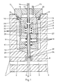
- FIG. 1 shows a section of a mold 1 of an injection molding machine with a mold cavity 3 enclosed between two mold surfaces 2 and 4, which can be partially or completely filled with a plasticized plastic melt by means of a nozzle, not shown, of a known type.
- a bore 5 is let into a part of the molding tool 1, which tapers at its end on the mold side and then merges into a further bore 6 with a smaller diameter.
- a nozzle 7 is inserted, which is locked in the bore 5 by means of a non-positive connection 8, for example a screw thread.
- the nozzle 7 initially consists of a two-part nozzle housing, which is composed of a nozzle body 9 and a nozzle chamber closure 10.
- the nozzle chamber closure 10 is formed in the case shown as a screw, for example as such with a hexagon screw head, with a central recess 11, the inner diameter of this central recess 11 being smaller than that of a piston 12 which can be displaced in the axial direction in the nozzle body 9, so that part of the screw end surface facing away from the head serves as a stop for the piston 12.
- the nozzle chamber closure 10 has a central bore 13 in the case shown, which acts as a sliding seal for an axially displaceable supply line 14 is used to supply the nozzle 7 with the second medium to be injected into the mold cavity 3, and also contains a non-positively connected supply line 15 for a pneumatic or hydraulic pressure medium to be inserted into or removed from the central recess 11.
- the nozzle chamber closure 10 is locked on the one hand by means of the non-positive connection 8 in the bore 5 and on the other hand carries the nozzle body 9 by means of further non-positive connections 16.
- the nozzle body 9 essentially represents a hollow cylinder in which a piston 12 is axially displaceable. At the end on the mold side, this nozzle body 9 initially has a constriction 17 of its inner diameter, which forms a further stop for the piston 12 and the seat for a spring 18, which is only indicated here, while a further constriction of its inner diameter then represents the mold-side outlet channel 19 of the nozzle 7 .
- the piston 12 is also a mechanically opening and non-positively locking hollow cylinder, the parting line and possible embodiment of a non-positive connection is not shown explicitly in the present illustration for the sake of simplicity.
- a further axially displaceable piston 20 with a central bore 21, in which an inner hollow needle 23 leading out of the piston 20 in the direction of the mold cavity 3 is locked by means of a non-positive connection 22, and one the Piston 20 in the idle state against the spring 24 holding the shape-facing end of the cavity.
- the inner cavity of the piston 12 is connected at its shape-facing end to the feed line 14 of the second medium, which by means of a non-positive connection 25 in a central bore 26 in the piston 12 is anchored.
- the piston 12 also has at its mold-side end a further central bore 27, in which a further Rich 28 by means of a non-positive connection device on the mold cavity 3 leading out of the piston 12 - outer - hollow needle 29 is locked.
- Bore 27 and outer hollow needle 29 are dimensioned such that the inner hollow needle 23 is at least in the outer hollow needle 29 fit to fit, without the movement of the bore 27 being impeded.
- the outlet channel 19 of the nozzle 7 and the bore 6 are designed so that the outer hollow needle 29 can slide in both bores in a fitting manner.
- Both hollow needles 23 and 29 are matched in length to one another in such a way that they end in the idle state on the mold side at the same level, in the case shown within the bore 6, with a different nozzle arrangement possibly also within the outlet channel 19, but in such a way that in front of the End faces 30 and 31 of both hollow needles 23 and 29 outside of the actual mold cavity 3 can store a part of the plastic melt injected first.
- the end faces 30 and 31 are designed such that they add largely to the level of the closest mold surface 2 when moving together. This means in particular that the end face 30 of the inner hollow needle 23 is closed.
- the inner hollow needle 23 has one or more outlet openings (32) for the second medium immediately behind its end face 30 Allow a plastic melt injected first to enter largely parallel to the mold surfaces 2 and 4.
- the mouth area of the bore 6 is provided with a heating device 33 and / or a special heat insulation 34, with the aid of which the part of the plastic melt which was initially injected and which was initially stored in the bore 6 is kept at a lower viscosity than the rest until a plug is formed the plastic melt injected first.
- Corresponding devices can optionally also be installed in the mouth area of the outlet channel 19 of the nozzle 7.
- FIG. 2 shows the position of the mold-side ends of the hollow needles 23 and 29 in various stages of an injection molding process, the starting position of which is already shown in FIG. 1.
- a first plastic melt 35 is first injected into the mold cavity 3 from a nozzle of a known type (not shown), part of this first plastic melt in the mouth region of the bore 6 outside of the hole 6 according to FIG. 2a with the ends of the hollow needles 23 and 29 unchanged actual mold cavity 3 is stored.
- the supply line 14 in FIG. 1 is pressurized by means of a known type of control, not shown, whereby the piston 20 is moved against the force of the spring 24 so far in the direction of the mold cavity 3 that the outlet openings 32 of the inner hollow needle 23 approximately open come to a stop halfway between the mold surfaces 2 and 4 and the second medium 36 transported through the feed line 14 and the hollow needle 23 according to FIG. 2b is pressed into the plastic melt 35 injected essentially parallel to the mold surfaces 2 and 4.
- the supply line 14 is connected to the atmosphere or a known type of storage container, which is under atmospheric pressure, by means of the control, not shown, of known type, whereby the second medium 36 in the injection molded plastic article is relieved of pressure and at the same time the piston 20 and move the inner hollow needle 23 back to its starting position according to FIG. 2c.
- the plastic melt first injected now forms a hollow body filled with the second medium 36 under approximately atmospheric pressure, one part the plastic melt is still stored in the mouth area of the bore 6.
- This part of the plastic melt 35 is now pressed down to the level of the mold surface 2, according to FIG. 2d, by applying a pneumatic or hydraulic pressure medium to the central recess 11 in the nozzle chamber closure 10 via the feed line 15, according to FIG. 1, via a supply line 15 so that the piston 12, ie at the same time also the piston 20 or the hollow needles 23 and 29, against the force of the spring 18, is moved so far in the direction of the nearest mold surface 2 that the end faces 30 and 31 of the hollow needles 23 and 29 complement the mold surface 2 essentially without interference.
- the feed line 15 is relieved of pressure by the known control system, not shown, so that the piston 12 and with it the piston 20 and the hollow needles 23 and 29 return to their starting position according to FIG. 1.
- the injection molding process is finished and can be repeated after the mold is closed again.
Abstract
Description
Die Erfindung betrifft eine Düse für Spritzgießmaschinen nach den Merkmalen des Oberbegriffs des Hauptanspruchs 1.The invention relates to a nozzle for injection molding machines according to the features of the preamble of main claim 1.
Eine gattungsgemäße Düse ist bereits aus der DE-OS 21 06 546 bekannt. Diese Düse trägt jedoch als Ausgangskanal nur eine fest mit ihr verbundene Hohlnadel konstanter Länge, die bei geschlossener Form stets bis zur plastischen Seele des mittels einer anderen Düse zunächst eingespritzten Kunststoffes reicht, beim Öffnen der Form nach der Verfestigung des zuerst eingespritzten Kunststoffes jedoch stets eine Öffnung oder zumindest - wenn das zweite Medium eine weitere Kunststoffkomponente ist - eine deutliche Störung der Oberfläche in dem gespritzten Kunststoffartikel hinterläßt. Dasselbe gilt für die gleichgestalteten Ausführungsbeispiele der Figuren 1 und 2 der GB-PS 2 139 548.A generic nozzle is already known from DE-OS 21 06 546. This nozzle, however, carries only a hollow needle of constant length, firmly connected with it, which, when the mold is closed, always extends to the plastic core of the plastic injected first by means of another nozzle, but always opens when the mold is opened after the plastic injected first is solidified or at least - if the second medium is a further plastic component - leaves a clear disturbance of the surface in the molded plastic article. The same applies to the identical embodiments of Figures 1 and 2 of GB-
Bei vielen spritzgegossenen Kunststoffartikeln sind derartige Öffnungen oder Störungen der Oberfläche jedoch unerwünscht. Diese Artikel müssen dann einer zusätzlichen Nachbehandlung unterzogen werden. Das gilt im übrigen auch für spritzgegossene Kunststoffartikel, die mit einer gattungsgemäßen Düse gemäß der britischen Patentanmeldung GB 2 202 181 hergestellt werden, die mit einer einzelnen, axial verschiebbaren Hohlnadel arbeitet, wobei der Innenraum der Hohlnadel die mit einem Rückschlagventil versehene Zuleitung des zweiten Mediums zum Formhohlraum bildet, während die Außenseite der Hohlnadel mit der Innenseite des Düsenkörper-Hohlraums im zurückgezogenen Zustand einen Ringspalt im Bereich des Düsenmundes bildet, der - jedenfalls dann, wenn das zweite Medium ein Druckgas oder eine unter Druck stehende Flüssigkeit ist - allein der Druckentspannung des zweiten Mediums nach der Verfestigung des zuerst eingespritzten Kunststoffes dient.In many injection molded plastic articles, however, such openings or surface defects are undesirable. These articles then have to undergo additional post-treatment. This also applies to injection-molded plastic articles that are produced with a generic nozzle according to British
Auch der Einsatz von - nicht mehr gattungsgemäßen - Zweikomponenten-Düsen gemäß der US-PS 4 101 617, der DE-PS 28 00 482 oder des Ausführungsbeispiels der Figur 5 in der GB-PS 2 139 548, bei denen während des Einspritzvorganges zumindest zeitweise mittels einer - axial verschiebbaren oder auch feststehenden - Hohlnadel ein zylindrischer Zentralstrang aus dem zweiten Medium von einem hohlzylindrischen Strang aus der die Außenhaut eines Kunststoffartikels bildenden Kunststoffschmelze umgeben wird, beseitigt das Problem der übrigbleibenden Öffnung oder zumindest deutlichen Störung der Oberfläche nicht. Entweder wird der Druck des zweiten Mediums bis zum Abbinden der äußeren Kunststoffschmelze in Form und Angußkanal von der Düse her aufrechterhalten - dann verbleibt im Anguß selbst eine Öffnung oder eine deutliche Störung der Oberfläche des Kunststoffartikels nach dem Entfernen des Angusses (vgl. beispielsweise Figuren 1-3, 1-4 sowie 2-1 bis 2-3 in der DE-PS 28 00 482 und das Ausführungsbeispiel in Figur 5 der GB-PS 2 139 548) - oder es wird nach dem Aufbau des vom zweiten Medium angefüllten Innenraumes des Kunststoffartikels im Formhohlraum ein Stopfen der äußeren Kunststoffschmelze nachgedrückt (vgl. Figur 3 der US-PS 4 101 617) - dann muß jedoch - jedenfalls dann, wenn das zweite Medium ein Druckgas oder eine unter Druck stehende Flüssigkeit ist - aus Sicherheitsgründen vor oder auch nach dem Öffnen der Form von außen eine zusätzliche Öffnung in den Kunststoffartikel gebohrt oder gestochen werden (vgl. ebenfalls Figuren 2 und 3 der US-PS 4 101 617). Darüber hinaus weisen Zweikomponenten-Düsen einen wesentlich komplizierteren konstruktiven Aufbau auf als Düsen für eine einzelne Komponente einer Spritzgießanlage, die gleichzeitig mehrere Komponenten verarbeitet, so daß es in vielen Fällen wartungsfreundlicher und preiswerter ist, eine Spritzgießanlage zur gleichzeitigen Verarbeitung von mehreren Komponenten mit mehreren Düsen für jeweils eine einzuspritzende Komponente anstatt mit einer einzigen Mehrkomponenten-Düse zu bestükken.The use of - no longer of the generic type - two-component nozzles according to US Pat. No. 4,101,617, DE-PS 28 00 482 or the exemplary embodiment of FIG. 5 in GB-
Die vorliegende Erfindung hat sich daher die Aufgabe gestellt, eine Düse für Spritzgießmaschinen zur Verfügung zu stellen, mit der ein zweites Medium in das Innere einer bereits teilweise oder vollständig in eine Spritzgießform eingespritzten ersten Kunststoffschmelze eingebracht werden kann, wobei diese Düse bei minimalem konstruktivem Aufbau einerseits das nahtlose Verschließen der Durchführungsöffnung für das zweite Medium durch die erste Kunststoffschmelze und andererseits - jedenfalls dann, wenn das zweite Medium ein Druckgas oder eine unter Druck stehende Flüssigkeit ist - die Druckentspannung des Innenraumes des Kunststoffartikels innerhalb der geschlossenen Form ohne externe Öffnung des Kunststoffartikels erlaubt.The object of the present invention is therefore to provide a nozzle for injection molding machines with which a second medium can be introduced into the interior of a first plastic melt that has already been partially or completely injected into an injection mold, this nozzle on the one hand with a minimal structural design the seamless closing of the passage opening for the second medium by the first plastic melt and, on the other hand - at least when the second medium is a pressurized gas or a pressurized liquid - allows the interior of the plastic article to be depressurized within the closed mold without an external opening of the plastic article.
Die Erfindung löst diese Aufgabe mit Hilfe der Merkmale des kennzeichnenden Teils des Hauptanspruchs 1.The invention solves this problem with the aid of the features of the characterizing part of main claim 1.
Als besonders vorteilhaft erweist es sich dabei, daß die erfindungsgemäße Düse in ihrem formseitigen Ausgangskanal zwei konzentrisch angeordnete, sowohl gegenüber der Wand des Ausgangskanals der Düse bzw. einer ihn ggf. bis zur Formoberfläche fluchtend fortsetzenden Bohrung als auch untereinander paßgerecht in axialer Richtung verschiebbare Hohlnadeln führt, wobei die innere Hohlnadel an ihrem formseitigen Ende verschlossen ist, dafür jedoch in ihrer Seitenwand oberhalb ihres formseitigen Endes eine oder mehrere Ausgangsöffnungen aufweist, und vorzugsweise soweit in den Formhohlraum ausgefahren werden kann, daß die Ausgangsöffnungen etwa auf der mittleren Höhe zwischen den beiden Formoberflächen im Bereich des Ausgangskanals bzw. der Bohrung ihren Arbeitspunkt erreichen. Mit dieser Anordnung läßt sich die innere Hohlnadel als Zuführung für das zweite Medium benutzen, die zunächst ausreichend tief in eine bereits im Formhohlraum befindliche erste Kunststoffschmelze eingefahren werden kann, um dann das zweite Medium im wesentlichen parallel und symmetrisch zu den Formoberflächen in die erste Kunststoffschmelze einzuspritzen, während die äußere Hohlnadel zunächst soweit zurückgezogen bleibt, daß sich zwischen innerer Hohlnadel und der Wand des Ausgangs kanals der Düse bzw. einer ihn bis zur Formoberfläche fluchtend fortsetzenden Bohrung im Formwerkzeug eine für die spätere Ausbildung eines Verschlußpfopfens ausreichende Menge von Material der ersten Kunststoffschmelze abspeichern kann. Insbesondere dann, wenn das zweite Medium ein Druckgas oder eine unter Druck stehende Flüssigkeit ist, läßt sich die ausgefahrene innere Hohlnadel vorteilhafterweise darüber hinaus nach dem Ausbilden einer inneren Blase des zweiten Mediums in der ersten Kunststoffschmelze und dem Beginn des Aushärtens der Außenschicht aus der ersten Kunststoffschmelze für den Druckausgleich zwischen Innenraum des Kunststoffkörpers und der Atmosphäre verwenden.It proves to be particularly advantageous here that the nozzle according to the invention has two concentrically arranged hollow needles in its mold-side outlet channel, both with respect to the wall of the outlet channel of the nozzle or a bore possibly flushing it up to the mold surface, and also with one another in the axial direction which can be displaced in a fitting manner , wherein the inner hollow needle is closed at its mold-side end, but instead has one or more exit openings in its side wall above its mold-side end, and preferably can be extended into the mold cavity to such an extent that the exit openings are approximately at the middle height between the two mold surfaces in the Area of the exit channel or the hole reach their working point. With this arrangement, the inner hollow needle can be used as a feed for the second medium, which can first be inserted sufficiently deep into a first plastic melt already in the mold cavity in order to then inject the second medium into the first plastic melt essentially parallel and symmetrically to the mold surfaces , while the outer hollow needle remains retracted so far that there is between the inner hollow needle and the wall of the exit channel of the nozzle or a bore in the mold, which continues flush to the mold surface, can store a sufficient amount of material of the first plastic melt for the subsequent formation of a sealing plug. In particular, if the second medium is a pressurized gas or a pressurized liquid, the extended inner hollow needle can advantageously also be formed after the formation of an inner bladder of the second medium in the first plastic melt and the beginning of the hardening of the outer layer from the first plastic melt use for pressure equalization between the interior of the plastic body and the atmosphere.
Vorteilhaft ist auch, daß die Endflächen der beiden Hohlnadeln bei gleichzeitigem Ausfahren beider Hohlnadeln auf das Niveau der nächstgelegenen Formoberfläche diese nahezu störungsfrei ergänzen. Dies gestattet, die innere Hohlnadel nach dem Herbeiführen eines Druckausgleichs zwischen Innenraum des Kunststoffkörpers und Atmosphäre zunächst soweit zurückzufahren, daß die Endflächen beider Hohlnadeln auf gleichem Niveau liegen, um dann beide Hohlnadeln gemeinsam bis zur nächstgelegenen Formoberfläche auszufahren, wobei der zuvor zwischen innerer Hohlnadel und Wand des Ausgangskanals der Düse bzw. einer ihn fluchtend fortsetzenden Bohrung im Formwerkzeug gespeicherte Vorrat an Material der ersten Kunststoffschmelze als nahtloser Pfropfen in die Außenwand des Kunststoffkörpers gedrückt wird. Dies insbesondere dann, wenn in einer weiteren vorteilhaften Ausgestaltung der erfindungsgemäßen Düse die Wand ihres formseitigen Ausgangskanals bzw. einer ihn bis zur Formoberfläche fluchtend fortsetzenden Bohrung im Formwerkzeug mit einer speziellen Wärmeisolierung und/oder einer Heizvorrichtung versehen ist.It is also advantageous that the end faces of the two hollow needles, while simultaneously extending both hollow needles to the level of the closest mold surface, complement these almost without any problems. This allows the inner hollow needle to be retracted after the pressure between the interior of the plastic body and the atmosphere has been equalized so that the end faces of both hollow needles are at the same level, in order to then extend both hollow needles together to the nearest mold surface, the one between the inner hollow needle and the wall of the outlet channel of the nozzle or a supply of material of the first plastic melt stored in the mold and continuing it in alignment is pressed as a seamless plug into the outer wall of the plastic body. This is particularly the case if, in a further advantageous embodiment of the nozzle according to the invention, the wall of its mold-side outlet channel or a bore in the mold that continues flush to the mold surface is provided with special heat insulation and / or a heating device.
Weitere vorteilhafte Ausgestaltungen der erfindungsgemäßen Düse, insbesondere bezüglich eines einfachen konstruktiven Aufbaus und einer leichten Handhabbarkeit, werden durch die Merkmale der Unteransprüche 4 bis 7 sowie 11 in Verbindung mit den kennzeichnenden Merkmalen des Hauptanspruchs 1 bzw. anderer jeweils vorausgegangener Ansprüche gegeben.Further advantageous configurations of the nozzle according to the invention, in particular with regard to a simple structural design and easy handling, are combined by the features of
Ein Ausführungsbeispiel einer erfindungsgemäßen Düse wird in der beigefügten Zeichnung dargestellt. Dabei zeigen:
- Fig. 1: Schnitt durch eine erfindungsgemäße Düse in Seitenansicht.
- Fig. 2: Stellung der Enden der Düsennadeln in verschiedenen Stadien eines Spritzgießvorganges mit einem zweiten Medium als Schnitt in Seitenansicht.
- Fig. 1: Section through a nozzle according to the invention in side view.
- Fig. 2: Position of the ends of the nozzle needles in different stages of an injection molding process with a second medium as a section in side view.
Die Fig. 1 zeigt einen Ausschnitt eines Formwerkzeuges 1 einer Spritzgießmaschine mit einem zwischen zwei Formoberflächen 2 und 4 eingeschlossenen Formhohlraum 3, der mittels einer nicht dargestellten Düse bekannter Art teilweise oder vollständig mit einer plastifizierten Kunststoffschmelze gefüllt werden kann. In einen Teil des Formwerkzeugs 1 ist eine Bohrung 5 eingelassen, die sich an ihrem formseitigen Ende verjüngt und dann in eine weitere Bohrung 6 mit kleinerem Durchmesser übergeht. In die Bohrung 5 ist eine Düse 7 eingesetzt, die in der Bohrung 5 mittels einer kraftschlüssigen Verbindung 8, beispielsweise eines Schraubgewindes, arretiert ist.1 shows a section of a mold 1 of an injection molding machine with a
Die Düse 7 besteht zunächst aus einem zweiteiligen Düsengehäuse, das sich aus einem Düsenkörper 9 und einem Düsenkammerverschluß 10 zusammensetzt. Der Düsenkammerverschluß 10 ist im gezeigten Fall als Schraube, beispielsweise als eine solche mit einem Sechskant-Schraubenkopf, mit einer zentrischen Ausnehmung 11 ausgebildet, wobei der Innendurchmesser dieser zentrischen Ausnehmung 11 kleiner ist als derjenige eines im Düsenkörper 9 in axialer Richtung verschiebbaren Kolbens 12, so daß ein Teil der kopfabgewandten Schraubenendfläche als Anschlag für den Kolben 12 dient. Der Düsenkammerverschluß 10 weist im gezeigten Fall eine zentrische Bohrung 13 auf, die als Gleitdichtung für eine axial verschiebbare Zuleitung 14 zur Versorgung der Düse 7 mit dem in den Formhohlraum 3 einzuspritzenden zweiten Medium dient, und enthält außerdem eine kraftschlüssig mit ihm verbundene Zuleitung 15 für ein in die zentrische Ausnehmung 11 ein- bzw. aus ihr herauszuführendes pneumatisches oder hydraulisches Druckmedium. Der Düsenkammerverschluß 10 ist einerseits mittels der kraftschlüssigen Verbindung 8 in der Bohrung 5 arretiert und trägt andererseits mittels weiterer kraftschlüssiger Verbindungen 16 den Düsenkörper 9.The
Der Düsenkörper 9 stellt im wesentlichen einen Hohlzylinder dar, in dem ein Kolben 12 axial verschiebbar ist. Am formseitigen Ende weist dieser Düsenkörper 9 zunächst eine Einschnürung 17 seines Innendurchmessers auf, die einen weiteren Anschlag für den Kolben 12 und den Sitz für eine hier nur angedeutete Feder 18 ausbildet, während eine nochmalige Einschnürung seines Innendurchmessers dann den formseitigen Ausgangskanal 19 der Düse 7 darstellt.The
Der Kolben 12 ist ebenfalls ein mechanisch zu öffnender und kraftschlüssig zu verschließender Hohlzylinder, dessen Trennfuge und mögliche Ausführungsform einer kraftschlüssigen Verbindung in der vorliegenden Darstellung der Einfachheit halber jedoch nicht explizit gezeigt wird. Im inneren Hohlraum des Kolbens 12 befinden sich ein weiterer axial verschiebbarer Kolben 20 mit einer zentrischen Bohrung 21, in der mittels einer kraftschlüssigen Verbindung 22 eine in Richtung auf den Formhohlraum 3 aus dem Kolben 20 herausführende - innere - Hohlnadel 23 arretiert ist, und eine den Kolben 20 im Ruhezustand gegen das formabgewandte Ende des Hohlraums haltende Feder 24. Der innere Hohlraum des Kolbens 12 ist im dargestellten Fall an seinem formabgewandten Ende mit der Zuleitung 14 des zweiten Mediums verbunden, die mittels einer kraftschlüssigen Verbindung 25 in einer zentrischen Bohrung 26 im Kolben 12 verankert ist. Der Kolben 12 weist außerdem an seinem formseitigen Ende eine weitere zentrische Bohrung 27 auf, in der mittels einer weiteren kraftschlüssigen Verbindung 28 eine in Rich tung auf den Formhohlraum 3 aus dem Kolben 12 herausführende - äußere - Hohlnadel 29 arretiert ist.The
Bohrung 27 und äußere Hohlnadel 29 sind derart dimensioniert, daß die innere Hohlnadel 23 zumindest in der äußeren Hohlnadel 29 paßgerecht verschiebbar ist, ohne daß die Bewegung von der Bohrung 27 behindert wird. Andererseits sind der Ausgangskanal 19 der Düse 7 und die Bohrung 6 so gestaltet, daß die äußere Hohlnadel 29 in beiden Bohrungen paßgerecht gleiten kann. Beide Hohlnadeln 23 und 29 sind in ihrer Länge so aufeinander abgestimmt, daß sie im Ruhezustand formseitig auf gleichem Niveau enden, im dargestellten Fall innerhalb der Bohrung 6, bei anderer Düsenanordnung ggf. auch innerhalb des Ausgangskanals 19, jedenfalls aber derart, daß sich vor den Endflächen 30 und 31 beider Hohlnadeln 23 und 29 außerhalb des eigentlichen Formhohlraums 3 ein Teil von zuerst eingespritzter Kunststoffschmelze abspeichern kann. Die Endflächen 30 und 31 sind so ausgebildet, daß sie bei gemeinsamer Verfahrung auf das Niveau der nächstgelegenen Formoberfläche 2 diese weitgehend störungsfrei ergänzen. Das bedeutet insbesondere, daß die Endfläche 30 der inneren Hohlnadel 23 geschlossen ist. Zum Auslaß des zweiten Mediums aus der inneren Hohlnadel 23 in den Formhohlraum 3 bzw. zur Druckentlastung einer Gas- oder Flüssigkeitsfüllung des spritzgegossenen Kunststoffartikels besitzt die innere Hohlnadel 23 dafür unmittelbar hinter ihrer Endfläche 30 eine oder mehrere Ausgangsöffnungen(en) 32, die das zweite Medium weitgehend parallel zu den Formoberflächen 2 und 4 in eine zuerst eingespritzte Kunststoffschmelze eintreten lassen.
Im dargestellten Fall ist der Mündungsbereich der Bohrung 6 mit einer Heizvorrichtung 33 und/oder einer speziellen Wärmeisolierung 34 versehen, mit deren Hilfe der zunächst in der Bohrung 6 abgespeicherte Teil der zuerst eingespritzten Kunststoffschmelze bis zur Ausbildung eines Verschlußpfropfens auf niedrigerer Viskosität gehalten wird als der Rest der zuerst eingespritzten Kunststoffschmelze. Entsprechende Vorrichtungen können ggf. auch im Mündungsbereich des Ausgangskanals 19 der Düse 7 installiert sein.In the case shown, the mouth area of the
Die Fig. 2 zeigt die Stellung der formseitigen Enden der Hohlnadeln 23 und 29 in verschiedenen Stadien eines Spritzgießvorganges, deren Ausgangsstellung bereits in Fig. 1 dargestellt ist. Ausgehend von diesem Ausgangszustand wird zunächst von einer nicht dargestellten Düse bekannter Art eine erste Kunststoffschmelze 35 in den Formhohlraum 3 eingespritzt, wobei gemäß Fig. 2a bei unveränderter Stellung der Enden der Hohlnadeln 23 und 29 ein Teil dieser ersten Kunststoffschmelze im Mündungsbereich der Bohrung 6 außerhalb des eigentlichen Formhohlraums 3 abgespeichert wird.FIG. 2 shows the position of the mold-side ends of the
Danach wird mittels einer nicht dargestellten Steuerung bekannter Art die Zuleitung 14 in Fig. 1 mit Druck beaufschlagt, wodurch der Kolben 20 gegen die Kraft der Feder 24 soweit in Richtung auf den Formhohlraum 3 verfahren wird, daß die Ausgangsöffnungen 32 der inneren Hohlnadel 23 etwa auf halber Höhe zwischen den Formoberflächen 2 und 4 zum Halten kommen und nun das durch die Zuleitung 14 und die Hohlnadel 23 herantransportierte zweite Medium 36 gemäß Fig. 2b im wesentlichen parallel zu den Formoberflächen 2 und 4 in die zuerst eingespritzte Kunststoffschmelze 35 eingedrückt wird.Thereafter, the
Nach dem Einsetzen des Abbindens der zuerst eingespritzten Kunststoffschmelze 35 wird die Zuleitung 14 mittels der nicht dargestellten Steuerung bekannter Art mit der Atmosphäre oder einem etwa unter Atmosphärendruck stehenden Vorratsbehälter bekannter Art verbunden, wodurch das zweite Medium 36 im spritzgegossenen Kunststoffartikel eine Druckentlastung erfährt und gleichzeitig der Kolben 20 und die innere Hohlnadel 23 gemäß Fig. 2c wieder in ihre Ausgangsstellung zurückfahren. Die zuerst eingespritzte Kunststoffschmelze bildet jetzt einen mit dem zweiten Medium 36 unter etwa Atmosphärendruck gefüllten Hohlkörper, wobei ein Teil der Kunststoffschmelze noch immer im Mündungsbereich der Bohrung 6 abgespeichert ist.After the setting of the first injected
Dieser Teil der Kunststoffschmelze 35 wird nun gemäß Fig. 2d auf das Niveau der Formoberfläche 2 heruntergedrückt, indem nach Fig. 1 die zentrische Ausnehmung 11 im Düsenkammerverschluß 10 über die Zuleitung 15 von einer nicht gezeigten Steuerung bekannter Art mit einem pneumatischen oder hydraulischen Druckmedium beaufschlagt und damit der Kolben 12, d.h. gleichzeitig auch der Kolben 20 bzw. die Hohlnadeln 23 und 29, gegen die Kraft der Feder 18 soweit in Richtung der nächstgelegenen Formoberfläche 2 verfahren wird, daß die Endflächen 30 und 31 der Hohlnadeln 23 und 29 die Formoberfläche 2 im wesentlichen störungsfrei ergänzen.This part of the
Wenn der so entstandene nahtlose Pfropfen aus dem Material der zuerst eingespritzten Kunststoffschmelze ausreichend abgebunden hat, wird die Zuleitung 15 von der nicht gezeigten Steuerung bekannter Art von der Druckbeaufschlagung entlastet, so daß der Kolben 12 und mit ihm der Kolben 20 sowie die Hohlnadeln 23 und 29 in ihre Ausgangsstellung gemäß Fig. 1 zurückkehren.When the resulting seamless plug from the material of the plastic melt injected first has set sufficiently, the
Mit dem anschließenden Öffnen der Form und dem Auswerfen des spritzgegossenen Kunststoffartikels ist der Spritzgießvorgang beendet und kann nach dem erneuten Schließen der Form wiederholt werden.With the subsequent opening of the mold and the ejection of the injection molded plastic article, the injection molding process is finished and can be repeated after the mold is closed again.
Die Verifizierung der Merkmale des kennzeichnenden Teils des Hauptanspruchs 1 ist selbstverständlich nicht auf das im Detail dargestellte Ausführungsbeispiel beschränkt.The verification of the features of the characterizing part of main claim 1 is of course not limited to the embodiment shown in detail.
- 1 Formwerkzeug1 mold
- 2, 4 Formoberflächen2, 4 mold surfaces
- 3 Formhohlraum3 mold cavity
- 5,6,13,21,26,27 Bohrungen5,6,13,21,26,27 holes
- 7 Düse7 nozzle
- 8,16,22,25,28 kraftschlüssige Verbindungen, beispielsweise Schraubgewinde8, 16, 22, 25, 28 non-positive connections, for example screw threads
- 9 Düsenkörper9 nozzle body
- 10 Düsenkammerverschluß10 nozzle chamber closure
- 11 zentrische Ausnehmung11 central recess
- 12, 20 Kolben12, 20 pistons
- 14, 15 Zuleitungen14, 15 feed lines
- 17 Einschnürung17 constriction
- 18, 24 Federn18, 24 springs
- 19 Ausgangskanal19 output channel
- 23, 29 Hohlnadeln23, 29 hollow needles
- 30, 31 Endflächen30, 31 end faces
- 32 Ausgangsöffnungen32 exit openings
- 33 Heizvorrichtung33 heater
- 34 Wärmeisolierung34 thermal insulation
- 35 Kunststoffschmelze35 plastic melt
- 36 zweites Medium36 second medium
Claims (10)
dadurch gekennzeichnet,
daß der formseitige Ausgangskanal (19) der Düse (7) und eine ihn ggf. bis zur Formoberfläche (2) fluchtend fortsetzende Bohrung (6) in dem die Düse tragenden Formwerkzeug (1) eine Anordnung aus zwei konzentrisch angeordneten, sowohl gegenüber der Wand des Ausgangskanals (19) bzw. der Bohrung (6) als auch untereinander paßgerecht in axialer Richtung verschiebbaren Hohlnadeln (23,29) führt, wobei die innere Hohlnadel (23) an ihrem formseitigen Ende verschlossen ist, dafür jedoch in ihrer Seitenwand oberhalb ihres formseitigen Endes eine oder mehrere Ausgangsöffnung(en) (32) aufweist, und die Endflächen (30,31) beider Hohlnadeln (23,29) bei gleichzeitigem Ausfahren auf das Niveau der nächstgelegenen Formoberfläche (2) diese nahezu störungsfrei ergänzen.1. Nozzle for injection molding machines for introducing a second medium, for example a gas, a liquid or another - foamable or non-foamable - plastic melt, into the interior of a first plastic melt that has already been partially or completely injected into an injection mold,
characterized,
that the mold-side outlet channel (19) of the nozzle (7) and a bore (6), possibly flush with it up to the mold surface (2), in the mold carrying the nozzle (1), an arrangement of two concentrically arranged, both with respect to the wall of the Output channel (19) or the bore (6) as well as hollow needles (23, 29) which can be displaced with respect to one another in the axial direction, the inner hollow needle (23) being closed at its mold-side end, but in its side wall above its mold-side end one or more outlet opening (s) (32), and the end faces (30, 31) of both hollow needles (23, 29), while simultaneously extending to the level of the closest mold surface (2), complement these almost without any problems.
dadurch gekennzeichnet,
daß die innere Hohlnadel (23) in den Formhohlraum (3) ausgefahren werden kann, und zwar vorzugsweise derart, daß die Ausgangsöffnungen (32) etwa auf der mittleren Höhe zwischen den Formoberflächen (2,4) im Bereich des Ausgangskanals (19) bzw. der Bohrung (6) ihren Arbeitspunkt erreichen.2. Nozzle for injection molding machines according to claim 1,
characterized,
that the inner hollow needle (23) can be extended into the mold cavity (3), preferably in such a way that the outlet openings (32) are approximately at the middle height between the mold surfaces (2, 4) in the region of the outlet channel (19) or the hole (6) reach its working point.
dadurch gekennzeichnet,
daß die äußere Hohlnadel (29) mindestens bis auf das Niveau der nächstgelegenen Formoberfläche (2) ausgefahren werden kann.3. Nozzle for injection molding machines according to one of claims 1 or 2,
characterized,
that the outer hollow needle (29) can be extended at least to the level of the closest mold surface (2).
dadurch gekennzeichnet,
daß die innere Hohlnadel (23) hydraulisch oder pneumatisch verfahren wird.4. Nozzle for injection molding machines according to one of the preceding claims 1 to 3,
characterized,
that the inner hollow needle (23) is moved hydraulically or pneumatically.
dadurch gekennzeichnet,
daß die innere Hohlnadel (23) von einem Anschlag aus gegen die Widerstandskraft einer Feder (24) verfahren wird.5. Nozzle for injection molding machines according to one of the preceding claims 1 to 4,
characterized,
that the inner hollow needle (23) is moved from a stop against the resistance of a spring (24).
dadurch gekennzeichnet,
daß die äußere Hohlnadel (29) hydraulisch oder pneumatisch verfahren wird.6. Nozzle for injection molding machines according to one of the preceding claims 1 to 5,
characterized,
that the outer hollow needle (29) is moved hydraulically or pneumatically.
dadurch gekennzeichnet,
daß die äußere Hohlnadel (29) von einem Anschlag aus gegen die Widerstandskraft einer Feder (18) verfahren wird.7. Nozzle for injection molding machines according to one of the preceding claims 1 to 6,
characterized,
that the outer hollow needle (29) is moved from a stop against the resistance of a spring (18).
dadurch gekennzeichnet,
daß die Wand des Ausgangskanals (19) und/oder der Bohrung (6) mit einer Heizvorrichtung (33) versehen werden kann.8. nozzle for injection molding machines according to one of the preceding claims 1 to 7,
characterized,
that the wall of the outlet channel (19) and / or the bore (6) can be provided with a heating device (33).
dadurch gekennzeichnet,
daß die Wand des Ausgangskanals (19) und/oder der Bohrung (6) mit einer speziellen Wärmeisolierung (34) versehen ist.9. Nozzle for injection molding machines according to one of the preceding claims 1 to 8,
characterized,
that the wall of the outlet channel (19) and / or the bore (6) is provided with a special thermal insulation (34).
dadurch gekennzeichnet,
daß sie einstückig in eine mit einem Innengewinde versehene Bohrung (5) im Formwerkzeug ein- bzw. aus einer solchen Bohrung (5) herausgeschraubt werden kann.10. Nozzle for injection molding machines according to one of the preceding claims 1 to 9,
characterized,
that it can be screwed in one piece into an internally threaded bore (5) in the molding tool or screwed out of such a bore (5).
Priority Applications (1)
| Application Number | Priority Date | Filing Date | Title |
|---|---|---|---|
| AT89118957T ATE74821T1 (en) | 1988-10-13 | 1989-10-12 | NOZZLE FOR INJECTION MOLDING MACHINES. |
Applications Claiming Priority (2)
| Application Number | Priority Date | Filing Date | Title |
|---|---|---|---|
| DE3834917A DE3834917A1 (en) | 1988-10-13 | 1988-10-13 | NOZZLE FOR INJECTION MOLDING MACHINES |
| DE3834917 | 1988-10-13 |
Publications (2)
| Publication Number | Publication Date |
|---|---|
| EP0363948A1 true EP0363948A1 (en) | 1990-04-18 |
| EP0363948B1 EP0363948B1 (en) | 1992-04-15 |
Family
ID=6365059
Family Applications (1)
| Application Number | Title | Priority Date | Filing Date |
|---|---|---|---|
| EP89118957A Expired - Lifetime EP0363948B1 (en) | 1988-10-13 | 1989-10-12 | Nozzle for injection-moulding machines |
Country Status (6)
| Country | Link |
|---|---|
| US (1) | US4990083A (en) |
| EP (1) | EP0363948B1 (en) |
| KR (1) | KR920004044B1 (en) |
| AT (1) | ATE74821T1 (en) |
| DE (2) | DE3834917A1 (en) |
| ES (1) | ES2032644T3 (en) |
Cited By (13)
| Publication number | Priority date | Publication date | Assignee | Title |
|---|---|---|---|---|
| EP0467201A2 (en) * | 1990-07-18 | 1992-01-22 | Toyoda Gosei Co., Ltd. | Mold for hollow injection molding |
| FR2682063A1 (en) * | 1991-10-04 | 1993-04-09 | Peguform Werke Gmbh | DIE SYSTEM FOR INJECTION MOLDING OF LARGE SURFACE ELEMENTS IN PLASTIC MATERIAL WITH CLOSED CAVITIES. |
| EP0577840A4 (en) * | 1991-12-27 | 1993-11-11 | Asahi Chemical Ind | Method of blow molding and pressurized fluid injection and discharge device therefor. |
| DE4240017A1 (en) * | 1992-11-27 | 1994-06-01 | Wolf Woco & Co Franz J | Hollow component prodn without centre core - involves injecting polymer to fill tool cavity and purging fluid polymer from centre to leave solidified walls with smooth inner surface |
| EP0639441A1 (en) * | 1993-08-17 | 1995-02-22 | MASCHINENFABRIK HENNECKE GmbH | Method and apparatus for foam filling housings with CFC-free polyurethane foams |
| FR2716135A1 (en) * | 1994-02-14 | 1995-08-18 | Braun Pebra Gmbh | Injection moulding machine |
| EP0668140A1 (en) * | 1994-02-15 | 1995-08-23 | M + C SCHIFFER GmbH | Method and apparatus for manufacturing toothbrushes |
| EP0679491A2 (en) * | 1994-04-28 | 1995-11-02 | Krauss-Maffei Aktiengesellschaft | Injection moulding machine for manufacturing hollow-walled containers |
| EP0714745A1 (en) * | 1994-12-02 | 1996-06-05 | Cheil Industries Inc. | Apparatus and process for injection molding a thermoplastic resin article |
| US7184009B2 (en) | 2002-06-21 | 2007-02-27 | Nokia Corporation | Display circuit with optical sensor |
| WO2014013304A1 (en) * | 2012-07-17 | 2014-01-23 | Illinois Tool Works Inc. | Method and device for producing a plastic part, especially a plastic part for an automobile, by an injection molding method |
| EP2614942B1 (en) * | 2012-01-11 | 2019-04-10 | Jsp Corporation | Method for producing skin-covered foamed molded article and apparatus for production thereof |
| EP3885100A1 (en) * | 2020-03-25 | 2021-09-29 | Braunform GmbH | Tool for injection moulding of plastic parts |
Families Citing this family (30)
| Publication number | Priority date | Publication date | Assignee | Title |
|---|---|---|---|---|
| DE3936289C2 (en) * | 1989-11-01 | 1996-01-25 | Battenfeld Gmbh | Device for injection molding plastic objects containing cavities |
| US5137680A (en) * | 1990-07-16 | 1992-08-11 | Milad Limited Partnership | Method of injection molding utilizing pressurized fluid source within a chamber in a mold |
| DE4024549C2 (en) * | 1990-08-02 | 1994-12-08 | Helphos Gmbh | Process for the production of injection molded parts |
| US5127814A (en) * | 1990-11-26 | 1992-07-07 | Nitrojection Corporation | Apparatus for producing a fluid-assisted injection molded product |
| US5200127A (en) * | 1990-12-17 | 1993-04-06 | Automotive Plastic Technologies, Inc. | Method and apparatus for gas assisted injection molding |
| US5304058A (en) * | 1991-06-12 | 1994-04-19 | Automotive Plastic Technologies | Injection nozzle |
| US5306134A (en) * | 1991-06-12 | 1994-04-26 | Automotive Plastic Technologies | Fluid forcing nozzle |
| US5282730A (en) * | 1991-06-12 | 1994-02-01 | Automotive Plastic Technologies | Retractable gas injection pin for an injection mold |
| US5256047A (en) * | 1991-12-03 | 1993-10-26 | Nitrojection Corporation | Gas assisted injection molding apparatus utilizing sleeve and pin arrangement |
| US5273417A (en) * | 1992-03-12 | 1993-12-28 | Automotive Plastic Technologies, Inc. | Nozzle for gas-assisted injection molding |
| DE4222510C1 (en) * | 1992-07-09 | 1993-12-09 | Edmund Ullisperger | Valve gate for plastic molding compounds |
| MY116615A (en) * | 1992-07-13 | 2004-03-31 | Aron Kasei Kk | Process for producing expanded plastics with skin and molding apparatus therefor |
| DE4237062C1 (en) * | 1992-11-03 | 1994-02-17 | Kloeckner Ferromatik Desma | Nozzle for injecting gas into injection mouldings without clogging - consists of porous tube made of sintered metal but whose cavity end is only open at specific points for maximum effectiveness |
| US5302337A (en) * | 1993-06-11 | 1994-04-12 | Cascade Engineering, Inc. | Method for making a coated gas-assisted injection molded article |
| US5464342A (en) * | 1993-09-24 | 1995-11-07 | Nitrojection Corporation | Pin in barrel injection molding nozzle using short pin |
| FR2731377B1 (en) * | 1995-03-06 | 1997-05-09 | Happich Mecanique | GAS INJECTOR FOR MOLDING HOLLOW PARTS OF PLASTIC MATERIAL |
| TW349914B (en) | 1995-10-19 | 1999-01-11 | Chrysler Corp | Car body part |
| US5698242A (en) * | 1995-12-20 | 1997-12-16 | General Instrument Corporation Of Delaware | Apparatus for the injection molding of semiconductor elements |
| US6159415A (en) * | 1996-03-18 | 2000-12-12 | Ricoh Company, Ltd. | Extended shaft and a mold of the extended shaft and an apparatus for molding the extended shaft and a method for molding the extended shaft |
| DE19713874B4 (en) * | 1997-04-04 | 2008-08-07 | Gardena Manufacturing Gmbh | Device for introducing gas into a mold |
| US6000925A (en) * | 1997-12-22 | 1999-12-14 | Alexander V. Daniels | Gas assisted injection molding system |
| DE19815681A1 (en) * | 1998-04-08 | 1999-10-14 | Thimm Verpackung Gmbh & Co | Injection molding process |
| KR100296969B1 (en) * | 1999-02-23 | 2001-09-22 | 허남욱 | Injection nozzle of synthetic resin for manufacturing card type moldings |
| DE10158663C1 (en) * | 2001-11-30 | 2003-05-08 | Siemens Ag | Production of branched plastic pipes comprises filling mold with plastic and then blow-molding to produce bores, bore in branch being produced by plug of plastic which is removed as main bore is blow molded |
| DE20209643U1 (en) * | 2002-06-21 | 2003-08-14 | Ergoplast Kunststoff Gmbh | Gas injection point closure system for production of hollow plastic products comprises a bulge on the molding at the gas injection point |
| US6739858B2 (en) * | 2002-08-29 | 2004-05-25 | Graham Packaging Company, L.P. | Insulated apparatus for injecting and removing compressed air from a cooled mold cavity |
| KR101606349B1 (en) | 2014-07-07 | 2016-03-30 | 김상태 | Tree growth Protection Device. |
| CN104162952B (en) * | 2014-08-14 | 2017-04-19 | 漳州立达信光电子科技有限公司 | LED lamp radiating shell and injection molding equipment thereof |
| US10179430B2 (en) * | 2016-02-15 | 2019-01-15 | Ge Aviation Systems Llc | Hybrid part manufacturing system and method |
| DE102021123797A1 (en) | 2021-09-15 | 2023-03-16 | Bayerische Motoren Werke Aktiengesellschaft | Injection molding method for producing a medium-conducting molded part and injection molded part |
Citations (1)
| Publication number | Priority date | Publication date | Assignee | Title |
|---|---|---|---|---|
| EP0250080A2 (en) * | 1986-05-19 | 1987-12-23 | Ladney, Michael | Method for injection molding |
Family Cites Families (8)
| Publication number | Priority date | Publication date | Assignee | Title |
|---|---|---|---|---|
| DE2106546A1 (en) * | 1971-02-11 | 1972-08-17 | Mohrbach E | Method and device for the injection molding of objects made of plastic |
| DE2501314A1 (en) * | 1975-01-15 | 1976-07-22 | Roehm Gmbh | INJECTION MOLDING OF HOLLOW MOLDED PARTS MADE OF THERMOPLASTIC PLASTICS, IN PARTICULAR FOR THE CONSTRUCTION SECTOR |
| GB1489291A (en) * | 1975-06-06 | 1977-10-19 | Weathershields Ltd | Open roof assemblies for vehicles |
| JPS59383B2 (en) * | 1977-01-05 | 1984-01-06 | 旭化成株式会社 | molding method |
| US4474717A (en) * | 1982-05-24 | 1984-10-02 | Lang Fastener Corporation | Method of making a twin-wall internally corrugated plastic structural part with a smooth non-cellular skin |
| GB2139548B (en) * | 1983-05-11 | 1986-11-19 | James Watson Hendry | Injection moulding |
| GB8706204D0 (en) * | 1987-03-16 | 1987-04-23 | Peerless Cinpres Ltd | Injection moulding apparatus |
| US4917594A (en) * | 1989-02-28 | 1990-04-17 | Mold-Masters Limited | Injection molding system with gas flow through valve gate |
-
1988
- 1988-10-13 DE DE3834917A patent/DE3834917A1/en active Granted
-
1989
- 1989-10-12 ES ES198989118957T patent/ES2032644T3/en not_active Expired - Lifetime
- 1989-10-12 EP EP89118957A patent/EP0363948B1/en not_active Expired - Lifetime
- 1989-10-12 DE DE8989118957T patent/DE58901171D1/en not_active Expired - Fee Related
- 1989-10-12 AT AT89118957T patent/ATE74821T1/en not_active IP Right Cessation
- 1989-10-13 KR KR1019890014670A patent/KR920004044B1/en not_active IP Right Cessation
- 1989-10-13 US US07/421,116 patent/US4990083A/en not_active Expired - Fee Related
Patent Citations (1)
| Publication number | Priority date | Publication date | Assignee | Title |
|---|---|---|---|---|
| EP0250080A2 (en) * | 1986-05-19 | 1987-12-23 | Ladney, Michael | Method for injection molding |
Cited By (23)
| Publication number | Priority date | Publication date | Assignee | Title |
|---|---|---|---|---|
| EP0467201A3 (en) * | 1990-07-18 | 1992-05-06 | Toyoda Gosei Co., Ltd. | Mold for hollow injection molding |
| US5198177A (en) * | 1990-07-18 | 1993-03-30 | Toyoda Gosei Co., Ltd. | Method of making a hollow molded product |
| US5295801A (en) * | 1990-07-18 | 1994-03-22 | Toyoda Gosei Co., Ltd. | Mold for hollow injection molding |
| EP0467201A2 (en) * | 1990-07-18 | 1992-01-22 | Toyoda Gosei Co., Ltd. | Mold for hollow injection molding |
| FR2682063A1 (en) * | 1991-10-04 | 1993-04-09 | Peguform Werke Gmbh | DIE SYSTEM FOR INJECTION MOLDING OF LARGE SURFACE ELEMENTS IN PLASTIC MATERIAL WITH CLOSED CAVITIES. |
| EP0577840A4 (en) * | 1991-12-27 | 1993-11-11 | Asahi Chemical Ind | Method of blow molding and pressurized fluid injection and discharge device therefor. |
| EP0577840A1 (en) * | 1991-12-27 | 1994-01-12 | Asahi Kasei Kogyo Kabushiki Kaisha | Method of blow molding and pressurized fluid injection and discharge device therefor |
| US5409659A (en) * | 1991-12-27 | 1995-04-25 | Asahi Kasei Kogyo Kabushiki Kaisha | Hollow injection-molding method and pressurized fluid introducing and discharging apparatus therefor |
| DE4240017C2 (en) * | 1992-11-27 | 2001-03-15 | Wolf Woco & Co Franz J | Process for the production of hollow molded parts which are open at least on two sides |
| DE4240017A1 (en) * | 1992-11-27 | 1994-06-01 | Wolf Woco & Co Franz J | Hollow component prodn without centre core - involves injecting polymer to fill tool cavity and purging fluid polymer from centre to leave solidified walls with smooth inner surface |
| EP0639441A1 (en) * | 1993-08-17 | 1995-02-22 | MASCHINENFABRIK HENNECKE GmbH | Method and apparatus for foam filling housings with CFC-free polyurethane foams |
| FR2716135A1 (en) * | 1994-02-14 | 1995-08-18 | Braun Pebra Gmbh | Injection moulding machine |
| EP0668140A1 (en) * | 1994-02-15 | 1995-08-23 | M + C SCHIFFER GmbH | Method and apparatus for manufacturing toothbrushes |
| EP0679491A2 (en) * | 1994-04-28 | 1995-11-02 | Krauss-Maffei Aktiengesellschaft | Injection moulding machine for manufacturing hollow-walled containers |
| EP0679491A3 (en) * | 1994-04-28 | 1996-08-07 | Krauss Maffei Ag | Injection moulding machine for manufacturing hollow-walled containers. |
| US5584470A (en) * | 1994-04-28 | 1996-12-17 | Krauss-Maffei Aktiengesellschaft | Method and apparatus for injection molding a hollow-wall container |
| EP0714745A1 (en) * | 1994-12-02 | 1996-06-05 | Cheil Industries Inc. | Apparatus and process for injection molding a thermoplastic resin article |
| US7184009B2 (en) | 2002-06-21 | 2007-02-27 | Nokia Corporation | Display circuit with optical sensor |
| EP2614942B1 (en) * | 2012-01-11 | 2019-04-10 | Jsp Corporation | Method for producing skin-covered foamed molded article and apparatus for production thereof |
| WO2014013304A1 (en) * | 2012-07-17 | 2014-01-23 | Illinois Tool Works Inc. | Method and device for producing a plastic part, especially a plastic part for an automobile, by an injection molding method |
| US9944003B2 (en) | 2012-07-17 | 2018-04-17 | Illinois Tool Works Inc. | Method and device for producing a plastic part, especially a plastic part for an automobile, by an injection molding method |
| DE102012014013B4 (en) | 2012-07-17 | 2022-02-24 | Illinois Tool Works Inc. | Method and device for producing a plastic part, in particular a plastic part for an automobile, in an injection molding process |
| EP3885100A1 (en) * | 2020-03-25 | 2021-09-29 | Braunform GmbH | Tool for injection moulding of plastic parts |
Also Published As
| Publication number | Publication date |
|---|---|
| ATE74821T1 (en) | 1992-05-15 |
| DE3834917A1 (en) | 1990-04-19 |
| DE58901171D1 (en) | 1992-05-21 |
| KR920004044B1 (en) | 1992-05-23 |
| US4990083A (en) | 1991-02-05 |
| KR900006094A (en) | 1990-05-07 |
| ES2032644T3 (en) | 1993-02-16 |
| EP0363948B1 (en) | 1992-04-15 |
| DE3834917C2 (en) | 1992-04-30 |
Similar Documents
| Publication | Publication Date | Title |
|---|---|---|
| EP0363948B1 (en) | Nozzle for injection-moulding machines | |
| EP0393315B1 (en) | Method for injection moulding fluid-filled plastic articles and apparatus for carrying out the method | |
| DE3936289C2 (en) | Device for injection molding plastic objects containing cavities | |
| EP1712341B1 (en) | Injection nozzle with two outlet orifices | |
| DE2342794B2 (en) | Method and device for the discontinuous production of multilayer molded parts from thermoplastic material | |
| DE3113294A1 (en) | "METHOD FOR PRODUCING A CERAMIC INVESTMENT MOLD" | |
| DE3245571A1 (en) | Needle shut-off nozzle for injection moulds | |
| DE2027514A1 (en) | Screw injection unit for plastics | |
| DE2259818B2 (en) | Injection molding device for producing a molded body with a core made of foamed and an outer skin made of unfoamed thermoplastic material | |
| EP0435025B1 (en) | Apparatus for introducing a gas into the cavity of an injection mould for making hollow plastic bodies | |
| DE2623308C3 (en) | Device for the discontinuous production of molded parts from thermoplastic material | |
| WO2004071742A1 (en) | Method for producing mould parts by injection and a plugged needle nozzle for an injection mould | |
| DE2342789C2 (en) | Device for the discontinuous production of multilayer moldings | |
| DE19703316B4 (en) | Method and device for producing a nozzle cartridge | |
| DE19947984A1 (en) | Injection molding machine, for gas-injection molding of thick walled plastic parts, comprises common nozzle for selectively injecting either plastic melt, gas or fluid | |
| DE10039864C5 (en) | injection molding nozzle | |
| EP0139841B1 (en) | Method and apparatus for producing a hollow thermoplastic body by blow-moulding | |
| DE19713874B4 (en) | Device for introducing gas into a mold | |
| DE3305931A1 (en) | Apparatus for discontinuously producing multilayer mouldings from plastic | |
| DE102011105765B4 (en) | Method for injection molding of plastic molded parts made of thermoplastic material | |
| DE1554934A1 (en) | Injection molding machine for processing plasticizable or meltable materials, in particular plastics | |
| DE19617484C1 (en) | Gas-displacement moulding equipment producing hollow vessels, contorted pipes or branchings | |
| DE19515741C3 (en) | Method and injection molding device for producing an at least partially hollow plastic body | |
| DE4132986C2 (en) | Nozzle arrangement for injection molding of large-area plastic parts with enclosed cavities | |
| DE1158239B (en) | Method and device for manufacturing plastic pipes |
Legal Events
| Date | Code | Title | Description |
|---|---|---|---|
| PUAI | Public reference made under article 153(3) epc to a published international application that has entered the european phase |
Free format text: ORIGINAL CODE: 0009012 |
|
| 17P | Request for examination filed |
Effective date: 19891012 |
|
| AK | Designated contracting states |
Kind code of ref document: A1 Designated state(s): AT BE CH DE ES FR GB IT LI NL SE |
|
| 17Q | First examination report despatched |
Effective date: 19910923 |
|
| ITF | It: translation for a ep patent filed |
Owner name: NOVELTY SERVICE ING. DI IORIO G. |
|
| GRAA | (expected) grant |
Free format text: ORIGINAL CODE: 0009210 |
|
| AK | Designated contracting states |
Kind code of ref document: B1 Designated state(s): AT BE CH DE ES FR GB IT LI NL SE |
|
| REF | Corresponds to: |
Ref document number: 74821 Country of ref document: AT Date of ref document: 19920515 Kind code of ref document: T |
|
| REF | Corresponds to: |
Ref document number: 58901171 Country of ref document: DE Date of ref document: 19920521 |
|
| GBT | Gb: translation of ep patent filed (gb section 77(6)(a)/1977) | ||
| ET | Fr: translation filed | ||
| PGFP | Annual fee paid to national office [announced via postgrant information from national office to epo] |
Ref country code: SE Payment date: 19920811 Year of fee payment: 4 |
|
| PGFP | Annual fee paid to national office [announced via postgrant information from national office to epo] |
Ref country code: FR Payment date: 19920814 Year of fee payment: 4 |
|
| PGFP | Annual fee paid to national office [announced via postgrant information from national office to epo] |
Ref country code: DE Payment date: 19920929 Year of fee payment: 4 |
|
| PGFP | Annual fee paid to national office [announced via postgrant information from national office to epo] |
Ref country code: BE Payment date: 19921002 Year of fee payment: 4 |
|
| PGFP | Annual fee paid to national office [announced via postgrant information from national office to epo] |
Ref country code: ES Payment date: 19921026 Year of fee payment: 4 |
|
| PGFP | Annual fee paid to national office [announced via postgrant information from national office to epo] |
Ref country code: AT Payment date: 19921028 Year of fee payment: 4 |
|
| PGFP | Annual fee paid to national office [announced via postgrant information from national office to epo] |
Ref country code: NL Payment date: 19921031 Year of fee payment: 4 |
|
| PGFP | Annual fee paid to national office [announced via postgrant information from national office to epo] |
Ref country code: CH Payment date: 19930129 Year of fee payment: 4 |
|
| REG | Reference to a national code |
Ref country code: ES Ref legal event code: FG2A Ref document number: 2032644 Country of ref document: ES Kind code of ref document: T3 |
|
| PLBE | No opposition filed within time limit |
Free format text: ORIGINAL CODE: 0009261 |
|
| STAA | Information on the status of an ep patent application or granted ep patent |
Free format text: STATUS: NO OPPOSITION FILED WITHIN TIME LIMIT |
|
| 26N | No opposition filed | ||
| PG25 | Lapsed in a contracting state [announced via postgrant information from national office to epo] |
Ref country code: GB Effective date: 19931012 Ref country code: AT Effective date: 19931012 |
|
| PG25 | Lapsed in a contracting state [announced via postgrant information from national office to epo] |
Ref country code: SE Effective date: 19931013 Ref country code: ES Free format text: LAPSE BECAUSE OF NON-PAYMENT OF DUE FEES Effective date: 19931013 |
|
| PG25 | Lapsed in a contracting state [announced via postgrant information from national office to epo] |
Ref country code: LI Effective date: 19931031 Ref country code: CH Effective date: 19931031 Ref country code: BE Effective date: 19931031 |
|
| BERE | Be: lapsed |
Owner name: KLOCKNER FERROMATIK DESMA G.M.B.H. Effective date: 19931031 |
|
| PG25 | Lapsed in a contracting state [announced via postgrant information from national office to epo] |
Ref country code: NL Effective date: 19940501 |
|
| GBPC | Gb: european patent ceased through non-payment of renewal fee |
Effective date: 19931012 |
|
| NLV4 | Nl: lapsed or anulled due to non-payment of the annual fee | ||
| PG25 | Lapsed in a contracting state [announced via postgrant information from national office to epo] |
Ref country code: FR Effective date: 19940630 |
|
| REG | Reference to a national code |
Ref country code: CH Ref legal event code: PL |
|
| PG25 | Lapsed in a contracting state [announced via postgrant information from national office to epo] |
Ref country code: DE Effective date: 19940701 |
|
| REG | Reference to a national code |
Ref country code: FR Ref legal event code: ST |
|
| EUG | Se: european patent has lapsed |
Ref document number: 89118957.3 Effective date: 19940510 |
|
| REG | Reference to a national code |
Ref country code: ES Ref legal event code: FD2A Effective date: 19990503 |
|
| PG25 | Lapsed in a contracting state [announced via postgrant information from national office to epo] |
Ref country code: IT Free format text: LAPSE BECAUSE OF NON-PAYMENT OF DUE FEES;WARNING: LAPSES OF ITALIAN PATENTS WITH EFFECTIVE DATE BEFORE 2007 MAY HAVE OCCURRED AT ANY TIME BEFORE 2007. THE CORRECT EFFECTIVE DATE MAY BE DIFFERENT FROM THE ONE RECORDED. Effective date: 20051012 |