EP0365770B1 - Spray can - Google Patents
Spray can Download PDFInfo
- Publication number
- EP0365770B1 EP0365770B1 EP89114600A EP89114600A EP0365770B1 EP 0365770 B1 EP0365770 B1 EP 0365770B1 EP 89114600 A EP89114600 A EP 89114600A EP 89114600 A EP89114600 A EP 89114600A EP 0365770 B1 EP0365770 B1 EP 0365770B1
- Authority
- EP
- European Patent Office
- Prior art keywords
- spray
- pump
- valve
- casing
- receiving container
- Prior art date
- Legal status (The legal status is an assumption and is not a legal conclusion. Google has not performed a legal analysis and makes no representation as to the accuracy of the status listed.)
- Expired - Lifetime
Links
Images


Classifications
-
- B—PERFORMING OPERATIONS; TRANSPORTING
- B05—SPRAYING OR ATOMISING IN GENERAL; APPLYING FLUENT MATERIALS TO SURFACES, IN GENERAL
- B05B—SPRAYING APPARATUS; ATOMISING APPARATUS; NOZZLES
- B05B9/00—Spraying apparatus for discharge of liquids or other fluent material, without essentially mixing with gas or vapour
- B05B9/03—Spraying apparatus for discharge of liquids or other fluent material, without essentially mixing with gas or vapour characterised by means for supplying liquid or other fluent material
- B05B9/04—Spraying apparatus for discharge of liquids or other fluent material, without essentially mixing with gas or vapour characterised by means for supplying liquid or other fluent material with pressurised or compressible container; with pump
- B05B9/08—Apparatus to be carried on or by a person, e.g. of knapsack type
- B05B9/085—Apparatus to be carried on or by a person, e.g. of knapsack type with a liquid pump
- B05B9/0855—Apparatus to be carried on or by a person, e.g. of knapsack type with a liquid pump the pump being motor-driven
- B05B9/0861—Apparatus to be carried on or by a person, e.g. of knapsack type with a liquid pump the pump being motor-driven the motor being electric
-
- B—PERFORMING OPERATIONS; TRANSPORTING
- B05—SPRAYING OR ATOMISING IN GENERAL; APPLYING FLUENT MATERIALS TO SURFACES, IN GENERAL
- B05B—SPRAYING APPARATUS; ATOMISING APPARATUS; NOZZLES
- B05B9/00—Spraying apparatus for discharge of liquids or other fluent material, without essentially mixing with gas or vapour
- B05B9/03—Spraying apparatus for discharge of liquids or other fluent material, without essentially mixing with gas or vapour characterised by means for supplying liquid or other fluent material
- B05B9/04—Spraying apparatus for discharge of liquids or other fluent material, without essentially mixing with gas or vapour characterised by means for supplying liquid or other fluent material with pressurised or compressible container; with pump
- B05B9/08—Apparatus to be carried on or by a person, e.g. of knapsack type
- B05B9/085—Apparatus to be carried on or by a person, e.g. of knapsack type with a liquid pump
- B05B9/0866—Apparatus to be carried on or by a person, e.g. of knapsack type with a liquid pump the pump being a gear, centrifugal or screw-type pump
Definitions
- the invention relates to a spray can with a spray mechanism for the atomization of liquids according to the preamble of patent claim 1.
- Spray cans and spray bottles of the aforementioned type are generally known in the trade. Mechanically actuated pumps spray a finely atomized liquid from a nozzle arranged on the housing. The use of pumps avoids the environmentally harmful propellant gases.
- a disadvantage of the known spray cans and spray bottles can also be seen in the fact that after the spray liquid has been removed, the entire spray can, including the pump mechanism, the line system and the outlet nozzle, is thrown away. This also destroys reusable and functional components.
- An electrosprayer is already known from US-A-4 618 099, in which the spray mechanism is inserted into a housing which is connected to the receptacle for the spray liquid by means of a screw connection.
- the spray mechanism has an electric motor-driven pump, the suction line of which protrudes through a bottom opening in the housing and into the receptacle for the spray liquid.
- the pump has a pressure pipe on the output side, which has an outlet nozzle for the spray jet at the front end. The pressure pipe with the spray nozzle protrudes from the housing.
- the ball valve with an adjustable spring inserted into the vent line on the outlet side has the advantage that air is automatically supplied in accordance with the spray liquid removed from the receiving container.
- the ball valve is actuated solely by the vacuum that forms in the receptacle when the liquid is removed.
- gear pump has the advantage that different spray liquids with different viscosities and compositions are safely delivered.
- the gear pump is driven in a simple manner by an electric motor with the interposition of a clutch.
- an overflow valve is used on the output side, which also serves as a safety valve on the pressure side.
- the spring which acts on the steel ball in the valve, can be adjusted in the conventional manner in the effective Be spring force.
- gears have any toothing, preferably involute toothing with a more precise flow rate.
- a particular advantage of the invention is also the combination of the upper housing with the entire spray mechanism and the screw-on receptacle for the spray liquid, for example.
- both housings form one unit. After the spray liquid has been removed from the receptacle, the housing is removed with the spray mechanism and simply connected to a new container with a new liquid. The entire upper part remains together with the spray mechanism and is environmentally friendly reusable.
- the helically coiled pressure pipe above the pump outlet side enables axial pump movements to be survived without damage and with a long service life due to springing up and down.
- the delivery quality is maintained with this coiled pressure line even if the spray can is turned through 180 ° and thus turned upside down.
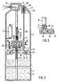
- the spray can 1 essentially consists of a housing 2 for accommodating the spray mechanism 3 and a receptacle 4 for the spray liquid 5 which is detachably connected to the housing 2.
- the housing 2 for the spray mechanism is cylindrical and has a head part 6.
- the spray mechanism 3 consists of a battery 7 to which an electric motor 8 is electrically connected.
- the electric motor 8 is connected with its output shaft 9 to a clutch 10, in which a drive shaft 11 of a gear pump 12 engages.
- a suction line 13 emerges below the gear pump 12, while in the upper part of the gear pump the pressure pipe 14 is connected, which opens into the outlet nozzle 15 in the head part 6 of the spray can.
- An overflow valve 16 with a ball 17 and an adjustable coil spring 18 is inserted in the pressure pipe 14 on the outlet side of the gear pump 12.
- the gear pump 12 consists of two equally large gears 19 and 20 which are in engagement with each other.
- spray liquid is drawn in from the suction line 13 and conveyed through the free tooth gaps to the pressure pipe 14 in the direction of the arrow 22.
- the gears 19 and 20 can be designed with an involute toothing for a precise flow. About fluctuations in funding To eliminate, can also be compensated by multi-wheel pumps, in which a medium gear with an odd number of teeth is used. Gear pumps with internal toothing and planet gear can also be used.
- the gear pump 12 is enclosed by a housing 23 which can be mounted on the bottom 24 of the housing 2 by screws 25.
- the receptacle 4 for the spray liquid 5 screwed onto the housing 2 by the central thread 31 has a vent line 26 which is equipped with a valve 27 on the outlet side of the housing 2.
- This valve consists of a ball 28 which is pressed by a spring 29 against the outlet opening 30.
- the spring 29 is designed so that when there is a vacuum in the receptacle when liquid is removed, it loses so much spring force that the ball 28 withdraws from the outlet opening 30 and allows air to flow into the receptacle 4.
- the housing 2 is connected to the receptacle 4 for the spray liquid 5 at the bottom 24 of the housing 2, where a collar 32 is provided which has an internal thread 31.
- the receptacle 4 is also formed on the head side with a collar 33 and has an external thread 34 which is firmly and sealingly engaged with the internal thread 31.
- FIG. 4 again shows a spray can 1, which essentially corresponds to the spray can according to FIGS. 1 and 2 and has a housing 2 for receiving the spray mechanism 3 and a further container 4 for the spray liquid 5.
- the base piece 35 of the housing 2 has a central collar 36 drawn inwards with an internal thread 31.
- the collar 35 closes at the top with a base plate 37, which is attached in one piece or separately can be and shows a central opening 38 for the passage of the suction pipe 13.
- the opening 38 receives an annular seal housing 39 with an inserted sealing tape or sealing ring 40.
- a decentralized opening 41 of relatively small cross section is provided in the base plate 37, through which the air pipe 26 projects as a ventilation line. A special seal between the ventilation line 26 and the opening 41 in the base plate is not required here.
- the container 4 for the spray liquid 5 has a central ring web 42 with an external thread 34 on the head side.
- the upper opening 43 is closed with a thin film 44.
- a removable cover made of solid material or a solution according to FIG. 7 can also be provided.
- connection of the housing 2 to the container 4 takes place in that the housing 2 is placed together with the spray mechanism 3 on the container 4 and screwed to the latter via the threads 31 and 34.
- the upper film 44 of the opening 43 is pierced by the suction pipe 13 and the air pipe 26 when the housing 2 is put on.
- connection types of housing 2 and container 4 of Figures 1, 2 and 4 can be exchanged and combined.
- the spray mechanism 3 consists of a battery 7 to which an electric motor 8 is electrically connected.
- the electric motor 8 drives an eccentric 46 via a reduction gear 45, which is operatively connected to the piston pump 48 via a slide 47.
- a suction pipe 13 emerges, while in the upper part of the piston pump 48 the helically coiled pressure pipe 14 is connected, which flows into an outlet nozzle 15 flows into.
- the electric motor 8 is switched by an electrical switch 49 with electrical switch contacts 50.
- An air tube 26 is also connected to the electrical switch 49 and has an only very small passage cross section of approximately two to five millimeters. Below the electrical switch 49, the air tube 26 can be closed by a spring-assisted valve 52 against the escape of liquid.
- a battery 7 is inserted or exchanged through the opening 54 in the cylinder wall of the housing 2, which can be closed with a cover 53.
- 55 denotes the helix of the pressure tube 14 or the flexible pressure line.
- a spray liquid 5 can be sprayed from the nozzle 15 in the head part 6 of the housing 2 at the push of a button.
- the receptacle 4 can be removed from the housing 2.
- the receptacle 4 can then either be reused by refilling with a spray liquid 5 or be sent to a landfill.
- it is possible to separate the receptacle 4 if the operator wants to use the same spray mechanism to remove another spray liquid from another receptacle. In this case, it makes sense that the upper opening 44 of the receptacle 4 has a sealable lid.
- connection between the housing 2 and the receptacle 4 can also be made by a conventional type of bayonet, plug-in or clamp lock.
- a plunger 51 opens the spring-assisted air valve 52, causing an inflow of air into the receptacle to compensate for the liquid withdrawn.
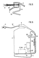
- FIG. 5 shows the possibility of laying the outlet nozzle 15 outside the head part 6 of the housing 2 of the spray can 1.
- an extension tube 56 is inserted in the head part 6, into which the pressure line 14 opens.
- the outlet nozzle 15 is attached.
- the extension tube 56 can also be a relatively long flexible or rigid line 57, for example one meter in length.
- the purpose of this is that ceilings or removed parts in living rooms, halls or similar rooms can be sprayed easily and specifically.
- the switching of the electric motor 8 for the function of the pump 12 or 48 is not carried out via the spray head 6 or the upper switch 49, but by means of a separate switch 58 in an additional operating or working handle 59 of the housing 2. From a socket 60 in the housing or on the housing 2, an electrical line 61 is guided in a very simplified drawing to the switch 58 in the control handle 59.
- the electric motor 8 is connected to the switch 58 in such a way by the electric lines 62 that when the switch 58 is depressed, an electrical connection is established between the socket 60 and the electric motor 8.
- an energy source prlug, mains
- a current flows to the electric motor 8, which starts the electric motor 8 and at the same time the connected pump 12 (48).
- the flexible or rigid pressure line 57 like the electrical lines 61, 62, is also laid in the control handle 59 up to the pump 12 (48).
- the pressure line 57 can be inserted and pulled out into the housing 2 and the operating handle 59.
- FIG. 7 a special locking security is provided in FIG. 7 in the form of a valve 63 known per se, to which the suction pipe 13 is connected.
- This valve 63 is inserted into the cover of the receptacle 4 and consists of the actual valve body 64, the valve spring 65 of the spring socket 66 inserted inside, the spring plate 67 and the outer seals 68, 69 and the inner seal 70.
- the valve 63 is pressed down against the force of the valve spring 65 and the valve is thereby opened.
- the spray liquid 5 can then emerge from the receptacle.
- the spray jet 71 can be improved when it emerges from the spray can 1 in that the spray liquid 5 is placed under a slight pressure of about 0.5 to 0.8 bar.
- a compressed gas for example nitrogen, is introduced into the receptacle 4 in addition to the spray liquid. This compressed gas also at least reduces the necessary suction power of the gear pump 12 or the piston pump 48, since the spray liquid 5 rises with the aid of pressure.
- the valve housing 75 is in the housing 2 of the spray can 1 a sealing ring 89 to the lower spray mechanism 3 with the pump 12 (48).
- the inlet opening 76 for the pressure line 14.
- the valve body 72 is under the action of a valve spring 74.
- the nozzle receptacle 79 is acted upon by a pressure piece 83, which is operatively connected to the head part 6 of the spray can 1, and has an upper stop 80 and a lower stop 81 lying axially one above the other. Between the lower stop 81 and the valve disc 73 are installed disk springs 82.
- the pressure piece 83 acts decentrally on a switching pin 84 under the action of a spring 85 which is axially spaced from a pressure pin 86. This in turn can be moved to a limit switch 87 which is fastened in the valve housing 75 by a screw 88.
- the head part 6 is usually depressed as a switch. Finally, valve body 72 is pressed against spring pressure via nozzle receptacle 79. The spray liquid 5 in the ring channel 77 of the valve 72 can escape into the upper pressure line 90 via the slot 78.
- the limit switch 87 are operated, which requires a smaller stroke of its switching plunger 91 than the valve disk 73 to open the slot 78.
- the stroke of the switching plunger 91 has a relatively large tolerance of approximately ⁇ 0.3 mm with respect to the switching point.
- the limit switch 87 must therefore already switch before the valve 72 opens. This is now through the Spring 85 reached, which actuates the switch 87 via the switching pin 84 when depressing the pressure piece 83.
Description
Die Erfindung betrifft eine Spraydose mit einem Spraymechanismus zur Feinzerstäubung von Flüssigkeiten nach dem Oberbegriff des Patentanspruchs 1.The invention relates to a spray can with a spray mechanism for the atomization of liquids according to the preamble of
Spraydosen und Sprayflaschen der vorgenannten Art sind im Handel allgemein bekannt. Durch mechanisch betätigbare Pumpen wird dabei aus einer am Gehäuse angeordneten Düse eine fein zerstäubte Flüssigkeit versprüht. Durch den Einsatz von Pumpen werden die umweltschädlichen Treibgase vermieden. Ein Nachteil der bekannten Spraydosen und Sprayflaschen ist auch darin zu sehen, daß nach der Entnahme der Sprayflüssigkeit die gesamte Spraydose mitsamt der Pumpenmechanik, dem Leitungssystem und der Austrittsdüse weggeworfen wird. Dadurch werden zusätzlich wiederverwendbare und funktionsfähige Bauelemente zerstört.Spray cans and spray bottles of the aforementioned type are generally known in the trade. Mechanically actuated pumps spray a finely atomized liquid from a nozzle arranged on the housing. The use of pumps avoids the environmentally harmful propellant gases. A disadvantage of the known spray cans and spray bottles can also be seen in the fact that after the spray liquid has been removed, the entire spray can, including the pump mechanism, the line system and the outlet nozzle, is thrown away. This also destroys reusable and functional components.
Durch die US-A-4 618 099 ist bereits ein Elektrosprayer bekannt, bei dem der Spraymechanismus in ein Gehäuse eingesetzt ist, das mit dem Aufnahmebehälter für die Sprayflüssigkeit durch eine Verschraubung verbunden ist. Der Spraymechanismus weist eine elektromotorisch angetriebene Pumpe auf, deren Saugleitung durch eine Bodenöffnung des Gehäuses bis in den Aufnahmebehälter für die Sprayflüssigkeit hineinragt. Die Pumpe besitzt abtriebsseitig ein Druckrohr, das am vorderen Ende eine Austrittsdüse für den Sprühstrahl zeigt. Das Druckrohr mit der Spraydüse ragt aus dem Gehäuse heraus.An electrosprayer is already known from US-A-4 618 099, in which the spray mechanism is inserted into a housing which is connected to the receptacle for the spray liquid by means of a screw connection. The spray mechanism has an electric motor-driven pump, the suction line of which protrudes through a bottom opening in the housing and into the receptacle for the spray liquid. The The pump has a pressure pipe on the output side, which has an outlet nozzle for the spray jet at the front end. The pressure pipe with the spray nozzle protrudes from the housing.
Ausgehend von dem vorgenannten Stand der Technik ist es Aufgabe der Erfindung, eine Spraydose der eingangs genannten Art dergestalt zu verbessern, daß die Zerstörung wiederverwendbarer Bauelemente vermieden wird, daß die Umweltbelastungen reduziert werden und daß ferner ein Spraymechanismus eingesetzt wird, der bei allen möglichen einsetzbaren Spraymedien eine einwandfreie Funktion auch im Langzeitbetrieb und unter den verschiedenen Sprühbedingungen gewährleistet.Starting from the aforementioned prior art, it is an object of the invention to improve a spray can of the type mentioned in such a way that the destruction of reusable components is avoided, the environmental pollution is reduced and that a spray mechanism is used which can be used with all possible spray media a perfect function is guaranteed even in long-term operation and under the different spray conditions.
Diese Aufgabe wird erfindungsgemäß durch die Merkmale des Patentanspruchs 1 gelöst. Weiterbildungen und besondere Ausgestaltungen dieser Lösungsmerkmale sind den Unteransprüchen 2 bis 8 zu entnehmen.This object is achieved by the features of
Das in die Entlüftungsleitung austrittsseitig eingesetzte Kugelventil mit einer einstellbaren Feder hat den Vorteil, daß entsprechend der aus dem Anfnahmebehälter entnommenen Sprayflüssigkeit automatisch eine Luftzuführung erfolgt. Die Betätigung des Kugelventils geschieht allein durch das sich im Aufnahmebehälter bei der Flüssigkeitsentnahme bildende Vakuum.The ball valve with an adjustable spring inserted into the vent line on the outlet side has the advantage that air is automatically supplied in accordance with the spray liquid removed from the receiving container. The ball valve is actuated solely by the vacuum that forms in the receptacle when the liquid is removed.
Der Einsatz einer Zahnradpumpe hat den Vorteil, daß unterschiedliche Sprayflüssigkeiten mit unterschiedlichen Viskositäten und Zusammensetzungen sicher gefördert werden. Der Antrieb der Zahnradpumpe erfolgt in einfacher Weise durch einen Elektromotor mit Zwischenschaltung einer Kupplung. Um ein Überlaufen der Sprayflüssigkeit nach dem Abschalten der Zahnradpumpe zu verhindern, wird abtriebsseitig ein Überlaufventil eingesetzt, das auch als Sicherheitsventil der Druckseite dient. Die Feder, die auf die Stahlkugel im Ventil wirkt, kann in herkömmlicher Weise einstellbar in der wirksamen Federkraft sein. Neben der in den Figuren gezeigten Ausführungsform der Zahnradpumpe mit zwei gleich großen und miteinander in Eingriff befindlichen Zahnrädern können auch andere Ausführungsformen, beispielsweise mit einer Innenverzahnung und Planetenrad zur Anwendung kommen. Ferner liegt es im Bereich der Erfindung, daß die Zahnräder eine beliebige Verzahnung, vorzugsweise eine Evolventenverzahnung mit einem genaueren Förderstrom besitzen.The use of a gear pump has the advantage that different spray liquids with different viscosities and compositions are safely delivered. The gear pump is driven in a simple manner by an electric motor with the interposition of a clutch. In order to prevent the spray liquid from overflowing after the gear pump is switched off, an overflow valve is used on the output side, which also serves as a safety valve on the pressure side. The spring, which acts on the steel ball in the valve, can be adjusted in the conventional manner in the effective Be spring force. In addition to the embodiment of the gear pump shown in the figures with two gear wheels of the same size and in engagement with one another, other embodiments, for example with an internal toothing and planet gear, can also be used. Furthermore, it is within the scope of the invention that the gears have any toothing, preferably involute toothing with a more precise flow rate.
Ein besonderer Vorteil der Erfindung liegt auch in der Kombination des oberen Gehäuses mit dem gesamten Spraymechanismus und dem beispielsweise anschraubbaren Aufnahmebehälter für die Sprayflüssigkeit. Im gekuppelten Zustand bilden beide Gehäuse eine Einheit. Nach der Entnahme der Sprayflüssigkeit aus dem Aufnahmebehälter wird das Gehäuse mit dem Spraymechanismus abgenommen und mit einem neuen Behälter mit einer neuen Flüssigkeit einfach verbunden. Der gesamte obere Teil bleibt zusammen mit dem Spraymechanismus erhalten und ist umweltfreundlich wiederverwendbar.A particular advantage of the invention is also the combination of the upper housing with the entire spray mechanism and the screw-on receptacle for the spray liquid, for example. When coupled, both housings form one unit. After the spray liquid has been removed from the receptacle, the housing is removed with the spray mechanism and simply connected to a new container with a new liquid. The entire upper part remains together with the spray mechanism and is environmentally friendly reusable.
Die für das Überlaufventil in der Druckleitung bezüglich der Zahnradpumpe geschilderten Vorteile gelten natürlich weitgehend auch für andere Pumpenarten, beispielsweise für Kolbenpumpen.The advantages described for the overflow valve in the pressure line with regard to the gear pump naturally also apply largely to other types of pumps, for example piston pumps.
Das schraubenlinienförmig gewendelte Druckrohr oberhalb der Pumpenautstrittsseite bringt die Möglichkeit, daß axiale Pumpenbewegungen durch federndes Auf- und Abschwingen ohne Schaden mit langer Lebensdauer überstanden werden. Die Förderqualität bleibt bei dieser gewendelten Druckleitung auch erhalten, wenn die Spraydose um 180° gedreht und damit auf den Kopf gestellt wird.The helically coiled pressure pipe above the pump outlet side enables axial pump movements to be survived without damage and with a long service life due to springing up and down. The delivery quality is maintained with this coiled pressure line even if the spray can is turned through 180 ° and thus turned upside down.
In der Zeichnung sind Beispiele der Erfindung dargestellt. Es zeigen:
Figur 1- eine Spraydose mit Spraymechanismus in schematischer Darstellung im Schnitt;
Figur 2- die Spraydose nach
Figur 1 mit im Schnitt dargestellter Zahnradpumpe; Figur 3- einen Schritt durch die Zahnradpumpe nach
Figur 2 gemäß der Linie III-III; - Figur 4
- eine Spraydose mit einer eingebauten Kolbenpumpe, schematisch im Schnitt;
Figur 5- einen Spraykopf mit außerhalb liegender Austrittsdüse im Schnitt;
Figur 6- eine Spraydose mit entfernt liegender Austrittsdüse und Schalter im Bediengriff;
- Figur 7
- ein Verschlußventil des Aufnahmebehälters;
Figur 8- eine Ventilanordnung bei einer Spraydose mit Druckgaseinsatz, vereinfacht im Schnitt.
- Figure 1
- a spray can with spray mechanism in a schematic representation in section;
- Figure 2
- the spray can of Figure 1 with the gear pump shown in section;
- Figure 3
- a step through the gear pump of Figure 2 along the line III-III;
- Figure 4
- a spray can with a built-in piston pump, schematically in section;
- Figure 5
- a spray head with an external outlet nozzle in section;
- Figure 6
- a spray can with the outlet nozzle removed and a switch in the control handle;
- Figure 7
- a closure valve of the receptacle;
- Figure 8
- a valve arrangement in a spray can with compressed gas insert, simplified on average.
Die Spraydose 1 besteht im wesentlichen aus einem Gehäuse 2 für die Aufnahme des Spraymechanismus 3 und einem mit dem Gehäuse 2 lösbar verbundenen Aufnahmebehälter 4 für die Sprayflüssigkeit 5.The spray can 1 essentially consists of a
Das Gehäuse 2 für den Spraymechanismus ist zylinderförmig gestaltet und weist ein Kopfteil 6 auf. Der Spraymechanismus 3 besteht aus einer Batterie 7, an die ein Elektromotor 8 elektrisch angeschlossen ist. Der Elektromotor 8 ist mit seiner Abtriebswelle 9 mit einer Kupplung 10 verbunden, in die eine Antriebswelle 11 einer Zahnradpumpe 12 eingreift. Unterhalb der Zahnradpumpe 12 tritt eine Saugleitung 13 aus, während im oberen Teil der Zahnradpumpe das Druckrohr 14 angeschlossen ist, welches in der Austrittsdüse 15 im Kopfteil 6 der Spraydose einmündet. In dem Druckrohr 14 ist austrittsseitig der Zahnradpumpe 12 ein Überlaufventil 16 mit einer Kugel 17 und einer einstellbaren Schraubenfeder 18 eingesetzt.The
Wie aus den Figuren 2 und 3 ersichtlich ist, besteht die Zahnradpumpe 12 aus zwei gleich großen Zahnrädern 19 und 20, die miteinander in Eingriff stehen. Bei Drehung der beiden Zahnräder in Pfeilrichtung 21 wird Sprayflüssigkeit aus der Saugleitung 13 angesaugt und durch die freien Zahnlücken zum Druckrohr 14 in Richtung des Pfeiles 22 gefördert.As can be seen from Figures 2 and 3, the
Die Zahnräder 19 und 20 können mit einer evolventen Verzahnung für einen genauen Förderstrom ausgebildet sein. Um Förderschwankungen zu beseitigen, kann darüberhinaus ein Ausgleich durch Mehrräderpumpen geschaffen werden, bei denen ein mittleres Zahnrad mit ungerader Zähnezahl eingesetzt wird. Darüberhinaus können auch Zahnradpumpen mit Innenverzahnung und Planetenrad eingesetzt werden.The
Die Zahnradpumpe 12 ist von einem Gehäuse 23 umschlossen, welches auf dem Boden 24 des Gehäuses 2 durch Schrauben 25 montierbar ist.The
Der an das Gehäuse 2 durch das zentrale Gewinde 31 angeschraubte Aufnahmebehälter 4 für die Sprayflüssigkeit 5 besitzt eine Entlüftungsleitung 26, die austrittsseitig aus dem Gehäuse 2 mit einem Ventil 27 ausgestattet ist. Dieses Ventil besteht aus einer Kugel 28, welche durch eine Feder 29 gegen die Austrittsöffnung 30 gedrückt wird. Dabei ist die Feder 29 so gestaltet, daß sie bei einem entstehenden Vakuum im Aufnahmebehälter bei Flüssigkeitentnahme so viel an Federkraft verliert, daß die Kugel 28 von der Austrittsöffnung 30 zurückweicht und ein Einströmen von Luft in den Aufnahmebehälter 4 ermöglicht.The receptacle 4 for the
Die Verbindung des Gehäuses 2 mit dem Aufnahmebehälter 4 für die Sprayflüssigkeit 5 erfolgt am Boden 24 des Gehäuses 2, wo ein Kragen 32 vorgesehen ist, der ein Innengewinde 31 aufweist. Der Aufnahmebehälter 4 ist kopfseitig ebenfalls mit einem Kragen 33 ausgebildet und weist ein Außengewinde 34 auf, das mit dem Innengewinde 31 fest und dichtend im Eingriff steht.The
Die Figur 4 zeigt wiederum eine Spraydose 1, die im wesentlichen der Spraydose nach den Figuren 1 und 2 entspricht und ein Gehäuse 2 für die Aufnahme des Spraymechanismus 3 und einen weiteren Behälter 4 für die Sprayflüssigkeit 5 besitzt. Das Bodenstück 35 des Gehäuses 2 weist einen zentralen und nach innen eingezogenen Kragen 36 mit einem Innengewinde 31 auf. Der Kragen 35 schließt nach oben mit einer Bodenplatte 37 ab, die einstückig oder getrennt angebracht sein kann und eine zentrale Öffnung 38 für den Durchtritt des Saugrohres 13 zeigt. Die Öffnung 38 nimmt ein ringförmiges Dichtungsgehäuse 39 mit eingelegtem Dichtungsband oder Dichtungsring 40 auf. Ferner ist in die Bodenplatte 37 eine dezentrale Öffnung 41 von relativ geringem Querschnitt vorgesehen, durch welche das Luftrohr 26 als Entlüftungsleitung hindurchragt. Hier ist eine besondere Abdichtung zwischen der Entlüftungsleitung 26 und der Öffnung 41 in der Bodenplatte nicht erforderlich.FIG. 4 again shows a
Der Behälter 4 für die Sprayflüssigkeit 5 besitzt kopfseitig einen zentralen Ringsteg 42 mit einem Außengewinde 34. Die obere Öffnung 43 ist in dem Beispiel der Figur 4 mit einer dünnen Folie 44 verschlossen. Anstelle der Folie 44 kann auch ein abnehmbarer Deckel aus festem Material oder eine Lösung nach Figur 7 vorgesehen werden.The container 4 for the
Die Verbindung des Gehäuses 2 mit dem Behälter 4 erfolgt dadurch, daß das Gehäuse 2 zusammen mit dem Spraymechanismus 3 auf den Behälter 4 aufgesetzt und mit diesem über das Gewinde 31 und 34 verschraubt wird. Die obere Folie 44 der Öffnung 43 wird bei dem Aufsetzen des Gehäuses 2 durch das Saugrohr 13 und das Luftrohr 26 durchstoßen.The connection of the
Selbstverständlich können die Verbindungsarten von Gehäuse 2 und Behälter 4 der Figuren 1, 2 und 4 ausgetauscht und miteinander kombiniert werden.Of course, the connection types of
Der Spraymechanismus 3 nach Figur 4 besteht aus einer Batterie 7, an die ein Elektromotor 8 elektrisch angeschlossen ist. Der Elektromotor 8 treibt über ein Untersetzungsgetriebe 45 einen Exzenter 46 an, der über einen Schieber 47 mit der Kolbenpumpe 48 in Wirkverbindung steht. Unterhalb der Kolbenpumpe 48 tritt ein Saugrohr 13 aus, während im oberen Teil der Kolbenpumpe 48 das schraubenlinienförmig gewendelte Druckrohr 14 angeschlossen ist, welches in eine Austrittsdüse 15 einmündet. Der Elektromotor 8 wird durch einen Elektroschalter 49 mit elektrischen Schaltkontakten 50 geschaltet. Mit dem Elektroschalter 49 ist außerdem ein Luftrohr 26 verbunden, das einen nur sehr kleinen Durchgangsquerschnitt von etwa zwei bis fünf Millimeter besitzt. Unterhalb des Elektroschalters 49 ist das Luftrohr 26 durch ein federunterstütztes Ventil 52 gegen das Austreten von Flüssigkeit verschließbar.The
Das Einsetzen bzw. das Auswechseln einer Batterie 7 erfolgt durch die mit einem Deckel 53 verschließbare Öffnung 54 in der Zylinderwand des Gehäuses 2. Mit 55 ist die Wendel des Druckrohres 14 bzw. der flexiblen Druckleitung bezeichnet.A battery 7 is inserted or exchanged through the
In dem in den Figuren 1, 2 und 4 gezeigten Zustand der Spraydose 1 kann eine Sprayflüssigkeit 5 durch Knopfdruck aus der Düse 15 im Kopfteil 6 des Gehäuses 2 versprüht werden. Nach vollständiger Entnahme der Sprayflüssigkeit und bei Bedarf auch in jedem Zwischenstadium kann der Aufnahmebehälter 4 von dem Gehäuse 2 abgenommen werden. Der Aufnahmebehälter 4 kann sodann entweder einer Wiederverwendung durch Nachfüllen mit einer Sprayflüssigkeit 5 zugeführt oder aber einer Deponie zugeführt werden. Natürlich ist es möglich, den Aufnahmebehälter 4 abzutrennen, wenn die Bedienungsperson mit dem gleichen Spraymechanismus eine andere Sprayflüssigkeit aus einem anderen Aufnahmebehälter entnehmen möchte. In diesem Fall bietet es sich an, daß die obere Öffnung 44 des Aufnahmebehälters 4 einen dichtverschließbaren Deckel aufweist.In the state of the spray can 1 shown in FIGS. 1, 2 and 4, a
Die Verbindung zwischen dem Gehäuse 2 und dem Aufnahmebehälter 4 kann alternativ zu der gezeigten Verschraubung auch durch einen Bajonett-, Steck- oder Klemmverschluß üblicher Bauart vorgenommen werden.As an alternative to the screw connection shown, the connection between the
Bei Betätigung des Elektroschalters 49 öffnet ein Stößel 51 das federunterstützte Luftventil 52, wodurch ein Einströmen von Luft in den Aufnahmebehälter als Ausgleich der entnommenen Flüssigkeit ermöglicht wird.When the
Figur 5 zeigt die Möglichkeit, die Austrittsdüse 15 außerhalb des Kopfteiles 6 des Gehäuses 2 der Spraydose 1 zu verlegen. Zu diesem Zweck ist im Kopfteil 6 ein Verlängerungsrohr 56 eingesetzt, in das die Druckleitung 14 einmündet. Am Ende des Verlängerungsrohres 56 ist die Austrittsdüse 15 angebaut.FIG. 5 shows the possibility of laying the
Das Verlängerungsrohr 56 kann entsprechend Figur 6 auch eine relativ lange flexible oder starre Leitung 57 von beispielsweise einem Meter Länge sein. Dies dient dazu, daß Decken oder entfernte Teile in Wohnräumen, Hallen oder dergleichen Räumlichkeiten einfach und gezielt besprüht werden können. In diesem Fall wird die Schaltung des Elektromotors 8 für die Funktion der Pumpe 12 oder 48 nicht über den Sprühkopf 6 oder den oberen Schalter 49 vorgenommen, sondern durch einen getrennten Schalter 58 in einem zusätzlichen Bedien- oder Arbeitsgriff 59 des Gehäuses 2. Von einer Steckdose 60 im Gehäuse oder am Gehäuse 2 ist eine elektrische Leitung 61 in sehr vereinfachter Zeichnungsdarstellung zum Schalter 58 im Bediengriff 59 geführt. Ferner ist der Elektromotor 8 mit dem Schalter 58 dergestalt durch die Elektroleitungen 62 verbunden, daß bei Niederdrücken des Schalters 58 eine elektrische Verbindung zwischen Steckdose 60 und Elektromotor 8 hergestellt wird. Bei Anschluß der Steckdose 60 an eine Energiequelle (Stecker, Netz) fließt zum Elektromotor 8 ein Strom, der den Elektromotor 8 und gleichzeitig die angeschlossene Pumpe 12 (48) in Betrieb setzt.According to FIG. 6, the
Die flexible oder starre Druckleitung 57 ist ebenfalls wie die Elektroleitungen 61, 62 im Bediengriff 59 bis zur Pumpe 12 (48) verlegt. Die Druckleitung 57 kann in das Gehäuse 2 und den Bediengriff 59 einschiebbar und herausziehbar gestaltet sein.The flexible or
Um den Aufnahmebehälter 4 für die Sprayflüssigkeit 5 durch unbefugte Personen nicht nachfüllen lassen zu können, damit Gefahren und die Nachfüllung mit schädlichen Flüssigkeiten oder Mitteln allgemein vermieden werden, ist in Figur 7 eine besondere Verschlußsicherheit in Form eines an sich bekannten Ventils 63 vorgesehen, an welches das Saugrohr 13 angeschlossen ist. Dieses Ventil 63 wird in den Deckel des Aufnahmebehälters 4 eingesetzt und besteht aus dem eigentlichen Ventilkörper 64, der innen eingesetzten Ventilfeder 65 der Federpfanne 66, dem Federteller 67 und den Außendichtungen 68, 69 sowie der Innendichtung 70. Beim Einschrauben des Aufnahmebehälters 4 in das Gehäuse in der dargestellten Form der Figuren 1, 2 und 4, wird das Ventil 63 entgegen der Kraft der Ventilfeder 65 heruntergedrückt und dadurch das Ventil geöffnet. Die Sprayflüssigkeit 5 kann dann aus dem Aufnahmebehälter austreten.In order not to allow the receiving container 4 for the
Wie sich in Erprobungen gezeigt hat, kann der Sprühstrahl 71 bei Austritt aus der Spraydose 1 dadurch verbessert werden, daß die Sprayflüssigkeit 5 unter einem leichten Druck von etwa 0,5 bis 0,8 bar gesetzt wird. Zu diesem Zweck wird in den Aufnahmebehälter 4 ein Druckgas, beispielsweise Stickstoff, zusätzlich zur Sprayflüssigkeit eingegeben. Durch dieses Druckgas wird auch die notwendige Ansaugleistung der Zahnradpumpe 12 oder der Kolbenpumpe 48 zumindest verringert, da das Aufsteigen der Sprayflüssigkeit 5 druckunterstützt erfolgt.As has been shown in tests, the
Wenn ein Druckgas in den Aufnahmebehälter 4 eingegeben ist, muß verhindert werden, daß der Sprühstrahl bzw. die Sprayflüssigkeit 5 nicht ungewollt aus der Austrittsdüse 15 austritt. Dies wird dadurch unterbunden, daß im Kopfteil 6 des Gehäuses 2 ein Ventil 72 eingebaut wird, wie es Figur 8 zeigt.If a pressurized gas is introduced into the receptacle 4, it must be prevented that the spray jet or the
Das Ventilgehäuse 75 ist im Gehäuse 2 der Spraydose 1 mit einem Dichtring 89 zum unteren Spraymechanismus 3 mit der Pumpe 12 (48) eingesetzt. Im Ventilgehäuse 75 befindet sich die Eintrittsöffnung 76 für die Druckleitung 14. Von der Eintrittsöffnung 76 geht ein Ringkanal 77 um den Ventilkörper 72 zur oberen Ventilscheibe 73, die ebenso wie der Ventilkörper 72 mit der Düsenaufnahme 79 zusammenwirkt. Der Ventilkörper 72 steht unter der Wirkung einer Ventilfeder 74. Die Düsenaufnahme 79 ist durch ein Druckstück 83, das mit dem Kopfteil 6 der Spraydose 1 wirkverbunden ist, beaufschlagt und besitzt axial übereinanderliegend einen oberen Anschlag 80 und einen unteren Anschlag 81. Zwischen dem unteren Anschlag 81 und der Ventilscheibe 73 sind Tellerfedern 82 eingebaut.The
Das Druckstück 83 beaufschlagt dezentral einen Schaltbolzen 84 unter der Wirkung einer Feder 85, der im axialen Abstand zu einem Druckbolzen 86 steht. Dieser wiederum ist auf einen Endschalter 87 bewegbar, der durch eine Schraube 88 im Ventilgehäuse 75 befestigt ist.The
Soll sein Sprühstrahl 71 erzeugt werden, so wird üblicherweise der Kopfteil 6 als Schalter niedergedrückt. Über die Düsenaufnahme 79 wird schließlich gegen Federdruck auf den Ventilkörper 72 gedrückt. Die Sprayflüssigkeit 5 im Ringkanal 77 des Ventils 72 kann über den Schlitz 78 in die obere Druckleitung 90 austreten. Damit die Pumpe 12 (48) vor dem Öffnen der Austrittsdüse 15 bzw. vor dem Öffnen des Ventils 72 um den Bruchteil einer Sekunde bereits in Betrieb sein soll, damit die Sprayflüssigkeit aus der Düse 15 nicht schon unter dem Gasdruck austritt, muß der Endschalter 87 betätigt werden, der einen kleineren Hub seines Schaltstößels 91 als die Ventilscheibe 73 zum Öffnen des Schlitzes 78 benötigt. Hinzu kommt noch, daß der Hub des Schaltstößels 91 in Bezug auf den Schaltpunkt eine relativ große Toleranz von etwa ± 0,3 mm aufweist. Der Endschalter 87 muß also bereits schalten, ehe das Ventil 72 öffnet. Dies wird nun durch die Feder 85 erreicht, die den Schalter 87 über den Schaltbolzen 84 beim Niederdrücken des Druckstückes 83 betätigt. Außerdem wird erreicht, daß nach dem Zurücklegen des maximalen Schalthubes durch den Druckbolzen 86 die Feder 85 zwar noch weiter zusammengedrückt wird, jedoch der Druckbolzen 86 an der Auflagefläche 92 des Ventilgehäuses 75 zur Anlage kommt. Der Druckbolzen 86 kann also axial nicht weiterbewegt werden, obwohl die Feder 85 noch zusammengedrückt wird, um den gesamten notwendigen Hub des Ventils 72 zu ermöglichen.If its
Claims (8)
- A spray can having a spray mechanism (3) for the fine atomisation of liquids, which is fitted into a casing (2) which can be connected by a positive locking action to a receiving container (4) for the spray liquid (5), wherein the spray mechanism (3) has an electric motor-driven pump (12; 48) whose intake conduit (13) is passed through a bottom opening in the casing (2) into the receiving container (4) and which on the output side has a pressure tube (14) which is connected to a discharge nozzle (15),
characterised in that
a vent conduit (26) extends into the receiving container (4) through the bottom (24; 35) of the casing (2), which vent conduit is closed at the discharge end by a ball (28) which is so subjected to the force of a spring (29) that a vacuum which occurs in the receiving container (4) when liquid is removed overcomes the spring force and the ball (28) opens the discharge opening (30), wherein the vent conduit (26) is also operatively connected to a motor switch (49) for the motor (8) of the spray mechanism (3), whose pressure tube (14) is provided on the output side of the pump (12; 48) with an overflow valve (16) in the form of a spring-supported ball (17) and is provided with a helical coil (55) of at least 180°. - A spray can according to claim 1 characterised in that
the pump is a gear pump (12). - A spray can according to claim 2 characterised in that
a coupling (10) is connected between the output shaft (9) of the motor (8) and the drive shaft (11) of the gear pump (12). - A spray can according to claims 2 and 3 characterised in that
the gear pap (12) has two gears (19, 20) of the same size. - A spray can according to claim 1 characterised in that
the pump is a piston pump (48). - A spray can according to claim 1 characterised in that
a pressure gas is introduced into the receiving container (4) in relation to the spray liquid (5) and provided in the upper part of the casing (2) is a transfer valve (72) which is coupled to the axial movement of the head part (6) for switching purposes, for the spray liquid (5) to pass through under pressure out of the receiving container (4), which valve in combination with a switching mechanism (84, 85, 86) of a limit switch (87, 91), for bringing the electric motor (8) of the pump (12; 48) into operation, acts in such a way that the limit switch (87, 91) is actuated just before opening of the valve (72) and the switching mechanism (84, 85, 86) absorbs the entire opening stroke movement of the valve (72) controlledly by spring force and transmits it in a regulated fashion to the limit switch (87, 91). - A spray can according to claim 1 characterised in that
the discharge nozzle (15) is connected outside the casing (2) to a pressure tube (14; 57) which is passed out of the casing (2) and which is in the form of a flexible conduit at least outside the casing (2). - A spray can according to claims 1 and 7 characterised in that
the casing (2) has an operating handle (59) in which the flexible conduit (57) is at least partially passed and into which there is further fitted a switch (58) which is electrically connected to a power source (60) and the electric motor (8) for the pump (12; 48).
Priority Applications (1)
| Application Number | Priority Date | Filing Date | Title |
|---|---|---|---|
| AT89114600T ATE88662T1 (en) | 1988-10-25 | 1989-08-08 | SPRAY CAN. |
Applications Claiming Priority (4)
| Application Number | Priority Date | Filing Date | Title |
|---|---|---|---|
| DE3836290 | 1988-10-25 | ||
| DE19883836290 DE3836290A1 (en) | 1988-10-25 | 1988-10-25 | Spray can |
| DE3916021 | 1989-05-17 | ||
| DE3916021A DE3916021A1 (en) | 1988-10-25 | 1989-05-17 | SPRAY CAN |
Publications (2)
| Publication Number | Publication Date |
|---|---|
| EP0365770A1 EP0365770A1 (en) | 1990-05-02 |
| EP0365770B1 true EP0365770B1 (en) | 1993-04-28 |
Family
ID=25873590
Family Applications (1)
| Application Number | Title | Priority Date | Filing Date |
|---|---|---|---|
| EP89114600A Expired - Lifetime EP0365770B1 (en) | 1988-10-25 | 1989-08-08 | Spray can |
Country Status (6)
| Country | Link |
|---|---|
| US (1) | US5014884A (en) |
| EP (1) | EP0365770B1 (en) |
| JP (1) | JPH02198656A (en) |
| DE (2) | DE3916021A1 (en) |
| ES (1) | ES2040946T3 (en) |
| HK (1) | HK116294A (en) |
Cited By (5)
| Publication number | Priority date | Publication date | Assignee | Title |
|---|---|---|---|---|
| USD432747S (en) | 1998-11-30 | 2000-10-24 | The Procter & Gamble Company | Bottle fitment |
| US6971549B2 (en) | 2003-04-18 | 2005-12-06 | S.C. Johnson & Son, Inc. | Bottle adapter for dispensing of cleanser from bottle used in an automated cleansing sprayer |
| US7021494B2 (en) | 2003-04-18 | 2006-04-04 | S. C. Johnson & Son, Inc. | Automated cleansing sprayer having separate cleanser and air vent paths from bottle |
| US7837132B2 (en) | 2002-05-28 | 2010-11-23 | S.C. Johnson & Son, Inc. | Automated cleansing sprayer |
| CN104670710A (en) * | 2015-01-25 | 2015-06-03 | 山西大学 | Automatic vacuum sealing box |
Families Citing this family (131)
| Publication number | Priority date | Publication date | Assignee | Title |
|---|---|---|---|---|
| DE4027749A1 (en) * | 1990-09-01 | 1992-03-05 | Pfeiffer Erich Gmbh & Co Kg | Discharge device for powdered medium - has air pump with compressed air stream picking up and ejecting powder |
| FR2671986B1 (en) * | 1991-01-29 | 1995-05-12 | Comceptair Anstalt | DEVICE FOR SPRAYING A LIQUID COMPRISING A PUSH-BUTTON WITH SPRAY JET FOR A REPETITION PUMP. |
| DE4231826A1 (en) * | 1992-09-23 | 1994-03-24 | Wunsch Eckart | Device for atomizing liquids |
| US5609300A (en) * | 1995-01-09 | 1997-03-11 | Campbell Hausfeld/Scott Fetzer Company | Airless paint sprayer outlet check valve |
| US5582957A (en) | 1995-03-28 | 1996-12-10 | Eastman Kodak Company | Resuspension optimization for photographic nanosuspensions |
| JPH09291879A (en) * | 1996-04-26 | 1997-11-11 | Canyon Corp | Pump dispenser |
| US6145711A (en) * | 1997-04-24 | 2000-11-14 | Black & Decker Inc. | Portable sprayer with power pump |
| US6125879A (en) * | 1997-08-20 | 2000-10-03 | Black & Decker Inc. | Release mechanism for a battery powered wheeled garden sprayer |
| US6142750A (en) * | 1998-11-30 | 2000-11-07 | The Procter & Gamble Company | Gear pump and replaceable reservoir for a fluid sprayer |
| US6343714B1 (en) * | 1999-06-11 | 2002-02-05 | Electro Spray Inc. | Anti-graffiti aerosol spray can having an internal spray head valve control assembly |
| CA2384857C (en) * | 1999-09-27 | 2005-05-24 | The Procter & Gamble Company | Cleaning implements |
| US6502766B1 (en) | 2000-07-24 | 2003-01-07 | The Procter & Gamble Company | Liquid sprayers |
| US6752330B2 (en) | 2000-07-24 | 2004-06-22 | The Procter & Gamble Company | Liquid sprayers |
| US6820821B2 (en) | 2001-04-13 | 2004-11-23 | S.C. Johnson & Son, Inc. | Automated cleansing sprayer |
| US7191920B2 (en) * | 2002-09-25 | 2007-03-20 | Conopco, Inc. | Motorized household liquid dispenser |
| US7147468B2 (en) | 2002-12-31 | 2006-12-12 | Water Pik, Inc. | Hand held oral irrigator |
| CN1761611B (en) * | 2003-03-21 | 2010-09-29 | 约瑟夫·坎弗 | Apparatus for hands-free dispensing of a measured quantity of material |
| US7588198B2 (en) * | 2003-12-18 | 2009-09-15 | S.C. Johnson & Son, Inc. | Power sprayer |
| US8602386B2 (en) * | 2007-12-21 | 2013-12-10 | S.C. Johnson & Son, Inc. | Valve with actuator assist |
| US7384006B2 (en) * | 2003-12-18 | 2008-06-10 | Cepia, Llc | Power sprayer |
| US7648083B2 (en) * | 2003-12-18 | 2010-01-19 | S.C. Johnson & Son, Inc. | Power sprayer |
| US7246755B2 (en) * | 2003-12-18 | 2007-07-24 | Cepia, Llc | Power sprayer |
| US7097119B2 (en) * | 2003-12-18 | 2006-08-29 | Cepia, Llc | Power sprayer |
| US7328859B2 (en) * | 2003-12-18 | 2008-02-12 | Cepia, Llc | Power sprayer |
| TWM256910U (en) * | 2004-02-05 | 2005-02-11 | Liung Feng Ind Co Ltd | Pressurization pumping device |
| US7222756B2 (en) * | 2004-06-16 | 2007-05-29 | Touch Free Applications Llc | Self-contained, portable and automatic fluid dispenser |
| US8061562B2 (en) | 2004-10-12 | 2011-11-22 | S.C. Johnson & Son, Inc. | Compact spray device |
| ES2319235T3 (en) | 2004-10-12 | 2009-05-05 | S.C. JOHNSON & SON, INC. | METHOD OF OPERATION OF A DISTRIBUTION UNIT. |
| US7455658B2 (en) * | 2004-11-10 | 2008-11-25 | Samw Hong Jen Wang | Fluid dispensing or feeding device |
| US7584872B2 (en) * | 2004-11-10 | 2009-09-08 | Samw Hong Jen Wang | Fluid dispensing or feeding device |
| US7516873B2 (en) * | 2004-11-10 | 2009-04-14 | Samw Hong Jen Wang | Fluid dispensing or feeding device |
| US20070203439A1 (en) | 2006-02-24 | 2007-08-30 | Water Pik, Inc. | Water jet unit and handle |
| WO2007101210A2 (en) * | 2006-02-27 | 2007-09-07 | Water Pik, Inc. | Tip for oral irrigator |
| US7670141B2 (en) | 2006-07-07 | 2010-03-02 | Water Pik, Inc. | Oral irrigator |
| KR100733006B1 (en) | 2006-09-01 | 2007-06-28 | 이영규 | A liquid extracting apparatus |
| USD802120S1 (en) | 2007-02-27 | 2017-11-07 | Water Pik, Inc. | Tip for oral irrigator |
| US8462508B2 (en) * | 2007-04-30 | 2013-06-11 | Hewlett-Packard Development Company, L.P. | Heat sink with surface-formed vapor chamber base |
| JP5142207B2 (en) * | 2008-05-27 | 2013-02-13 | 株式会社三谷バルブ | Electric content discharge mechanism and content discharge product equipped with electric content discharge mechanism |
| US20100072300A1 (en) * | 2008-09-24 | 2010-03-25 | Miller William S | Paint sprayer |
| US8196846B2 (en) * | 2008-12-02 | 2012-06-12 | S.C. Johnson & Son, Inc. | Manifold for automated sprayer |
| US20100167236A1 (en) * | 2008-12-29 | 2010-07-01 | Koninklijke Philips Electronics N.V. | Non-pressurized system fore creating liquid droplets in a dental cleaning appliance |
| US20100190132A1 (en) | 2009-01-28 | 2010-07-29 | Water Pik, Inc. | Oral irrigator tip |
| US10258442B2 (en) | 2009-03-20 | 2019-04-16 | Water Pik, Inc. | Oral irrigator appliance with radiant energy delivery for bactericidal effect |
| US8413850B1 (en) * | 2009-09-01 | 2013-04-09 | Fernando Gambach | Pump device for bottles |
| US8459499B2 (en) | 2009-10-26 | 2013-06-11 | S.C. Johnson & Son, Inc. | Dispensers and functional operation and timing control improvements for dispensers |
| USD629884S1 (en) | 2009-12-16 | 2010-12-28 | Water Pik, Inc. | Powered irrigator for sinus cavity rinse |
| US9061096B2 (en) | 2009-12-16 | 2015-06-23 | Water Pik, Inc. | Powered irrigator for sinus cavity rinse |
| ES2687423T3 (en) * | 2010-10-08 | 2018-10-25 | 3M Innovative Properties Company | Production method of a colored plastic article |
| USD670373S1 (en) | 2010-12-16 | 2012-11-06 | Water Pik, Inc. | Powered irrigator for sinus cavity rinse |
| US20140231549A1 (en) * | 2011-09-28 | 2014-08-21 | Sensile Pat Ag | Fluid dispensing system |
| WO2014059362A2 (en) | 2012-10-11 | 2014-04-17 | Water Pik, Inc. | Interdental cleaner using water supply |
| USD707350S1 (en) | 2012-10-11 | 2014-06-17 | Water Pik, Inc. | Handheld water flosser |
| US9108782B2 (en) | 2012-10-15 | 2015-08-18 | S.C. Johnson & Son, Inc. | Dispensing systems with improved sensing capabilities |
| US9663932B2 (en) | 2012-10-29 | 2017-05-30 | Xela Innovations, Llc | Fixture cleaning and deodorizing apparatus and method of use |
| US9453330B2 (en) | 2012-10-29 | 2016-09-27 | Xela Innovations, Llc | Fixture cleaning and deodorizing apparatus and method of use |
| USD725770S1 (en) | 2013-03-14 | 2015-03-31 | Water Pik, Inc. | Reservoir for water flosser |
| USD788907S1 (en) | 2013-03-14 | 2017-06-06 | Water Pik, Inc. | Water flosser base unit with reservoir lid |
| USD717427S1 (en) | 2013-03-14 | 2014-11-11 | Water Pik, Inc. | Handle for water flosser |
| USD714929S1 (en) | 2013-03-14 | 2014-10-07 | Water Pik, Inc. | Base for water flosser |
| US9642677B2 (en) | 2013-03-14 | 2017-05-09 | Water Pik, Inc. | Oral irrigator with massage mode |
| US8889082B2 (en) | 2013-03-15 | 2014-11-18 | San Jamar, Inc. | Apparatus for metered dose of odor control substance |
| US20140361101A1 (en) * | 2013-06-06 | 2014-12-11 | RealXGear | Personal misting device |
| US9321062B1 (en) * | 2013-09-18 | 2016-04-26 | Willie E. Hawkins, Jr. | Troweling system with fluid misting component |
| US9980793B2 (en) | 2013-11-27 | 2018-05-29 | Water Pik, Inc. | Oral hygiene system |
| EP3485843B1 (en) | 2013-11-27 | 2020-05-13 | Water Pik, Inc. | Oral irrigator with tip release assembly |
| CN203693808U (en) | 2013-12-12 | 2014-07-09 | 洁碧有限公司 | Dental water sprayer |
| US10220109B2 (en) | 2014-04-18 | 2019-03-05 | Todd H. Becker | Pest control system and method |
| WO2015161250A1 (en) | 2014-04-18 | 2015-10-22 | Conroy Thomas A | Diffusion management system |
| USD772397S1 (en) | 2014-12-01 | 2016-11-22 | Water Pik, Inc. | Oral irrigator with a charging device |
| USD772396S1 (en) | 2014-12-01 | 2016-11-22 | Water Pik, Inc. | Handheld oral irrigator |
| CN205586102U (en) | 2014-12-01 | 2016-09-21 | 洁碧有限公司 | Waterproof wireless oral cavity flusher |
| ES2791898T3 (en) * | 2015-02-25 | 2020-11-06 | Am Tuotanto Oy | Applicator |
| USD780908S1 (en) | 2015-11-03 | 2017-03-07 | Water Pik, Inc. | Handheld oral irrigator |
| USD822196S1 (en) | 2016-01-14 | 2018-07-03 | Water Pik, Inc. | Oral irrigator |
| USD794773S1 (en) | 2016-07-19 | 2017-08-15 | Water Pik, Inc. | Oral irrigator |
| USD802747S1 (en) | 2016-07-19 | 2017-11-14 | Water Pik, Inc. | Reservoir for oral irrigator |
| USD782656S1 (en) | 2016-01-25 | 2017-03-28 | Water Pik, Inc. | Oral irrigator |
| EP4292564A3 (en) | 2016-01-25 | 2024-02-28 | Water Pik, Inc. | Reduced form factor oral irrigator |
| USD783809S1 (en) | 2016-01-25 | 2017-04-11 | Water Pik, Inc. | Oral irrigator handle |
| USD819956S1 (en) | 2016-01-25 | 2018-06-12 | Water Pik, Inc. | Kit bag |
| USD786422S1 (en) | 2016-01-25 | 2017-05-09 | Water Pik, Inc. | Oral irrigator |
| USD796028S1 (en) | 2016-07-19 | 2017-08-29 | Water Pik, Inc. | Oral irrigator |
| USD804018S1 (en) | 2016-07-19 | 2017-11-28 | Water Pik, Inc. | Base for an oral irrigator |
| US10835356B2 (en) | 2016-01-25 | 2020-11-17 | Water Pik, Inc. | Swivel assembly for oral irrigator handle |
| USD804016S1 (en) | 2016-02-05 | 2017-11-28 | Water Pik, Inc. | Handheld oral irrigator |
| USD809650S1 (en) | 2016-02-22 | 2018-02-06 | Water Pik, Inc. | Oral irrigator |
| USD783810S1 (en) | 2016-02-22 | 2017-04-11 | Water Pik, Inc. | Handle for an oral irrigator |
| USD802119S1 (en) | 2016-03-02 | 2017-11-07 | Water Pik, Inc. | Oral irrigator |
| JP6949041B2 (en) | 2016-03-02 | 2021-10-20 | ウォーター・ピック,インク. | Operating assembly for mouthwash |
| USD782657S1 (en) | 2016-03-02 | 2017-03-28 | Water Pik, Inc. | Oral irrigator handle |
| AU2017295485A1 (en) * | 2016-07-11 | 2019-01-24 | Bayer Cropscience Aktiengesellschaft | Spray device with unpressurised spray material containers |
| USD809651S1 (en) | 2016-07-19 | 2018-02-06 | Water Pik, Inc. | Combination base and reservoir for an oral irrigator |
| USD807822S1 (en) | 2016-07-19 | 2018-01-16 | Water Pik, Inc. | Power supply cartridge |
| AU2017306411B2 (en) | 2016-08-03 | 2022-03-31 | Scentbridge Holdings, Llc | Method and system of a networked scent diffusion device |
| US10373477B1 (en) | 2016-09-28 | 2019-08-06 | Gojo Industries, Inc. | Hygiene compliance modules for dispensers, dispensers and compliance monitoring systems |
| CN106423626A (en) * | 2016-12-05 | 2017-02-22 | 暨南大学 | Spraying device |
| USD833000S1 (en) | 2016-12-15 | 2018-11-06 | Water Pik, Inc. | Oral irrigator unit |
| USD829886S1 (en) | 2016-12-15 | 2018-10-02 | Water Pik, Inc. | Oral irrigator base |
| USD833600S1 (en) | 2016-12-15 | 2018-11-13 | Water Pik, Inc. | Oral irrigator reservoir |
| USD839409S1 (en) | 2016-12-15 | 2019-01-29 | Water Pik, Inc. | Oral irrigator unit |
| USD825741S1 (en) | 2016-12-15 | 2018-08-14 | Water Pik, Inc. | Oral irrigator handle |
| USD822826S1 (en) | 2016-12-15 | 2018-07-10 | Water Pik, Inc. | Oral irrigator base |
| USD840023S1 (en) | 2016-12-15 | 2019-02-05 | Water Pik, Inc. | Oral irrigator reservoir |
| USD834180S1 (en) | 2016-12-15 | 2018-11-20 | Water Pik, Inc. | Oral irrigator base |
| USD840022S1 (en) | 2016-12-15 | 2019-02-05 | Water Pik, Inc. | Oral irrigator handle |
| USD832418S1 (en) | 2016-12-15 | 2018-10-30 | Water Pik, Inc. | Oral irrigator base |
| CA3046973C (en) | 2016-12-15 | 2021-07-20 | Water Pik, Inc. | Pause valve and swivel assemblies for oral irrigator handle |
| USD822825S1 (en) | 2016-12-15 | 2018-07-10 | Water Pik, Inc. | Oral irrigator unit |
| USD867579S1 (en) | 2016-12-15 | 2019-11-19 | Water Pik, Inc. | Oral irrigator unit |
| USD832420S1 (en) | 2016-12-15 | 2018-10-30 | Water Pik, Inc. | Oral irrigator base |
| USD832419S1 (en) | 2016-12-15 | 2018-10-30 | Water Pik, Inc. | Oral irrigator unit |
| JP7146762B2 (en) | 2016-12-15 | 2022-10-04 | ウォーター ピック インコーポレイテッド | Oral irrigator with magnetic attachment |
| USD833602S1 (en) | 2017-02-06 | 2018-11-13 | Water Pik, Inc. | Oral irrigator base |
| USD833601S1 (en) | 2017-02-06 | 2018-11-13 | Water Pik, Inc. | Oral irrigator |
| USD829887S1 (en) | 2017-02-06 | 2018-10-02 | Water Pik, Inc. | Oral irrigator reservoir |
| DE102017004986A1 (en) | 2017-05-24 | 2018-11-29 | Chunhui Gu | Electric spray bottle for foodstuffs for evenly spraying the liquid on food when frying or preparing the dish |
| CN212943592U (en) * | 2017-07-27 | 2021-04-13 | 米沃奇电动工具公司 | Power liquid sprayer |
| US10800644B2 (en) * | 2017-09-15 | 2020-10-13 | Hiketron Inc. | Metering apparatus for dispensing household and industrial fluids and methods for making and using same |
| US10213799B1 (en) * | 2017-12-18 | 2019-02-26 | Edward Lee Roczey | Multi-use portable hand-held sprayer |
| USD868243S1 (en) | 2018-03-16 | 2019-11-26 | Water Pik, Inc. | Oral irrigator tip |
| USD877324S1 (en) | 2018-05-17 | 2020-03-03 | Water Pik, Inc. | Oral irrigator handle |
| USD919045S1 (en) | 2018-09-12 | 2021-05-11 | 3M Innovative Properties Company | Liquid delivery system coupler |
| USD898868S1 (en) | 2018-09-12 | 2020-10-13 | 3M Innovative Properties Company | Liquid delivery system lid |
| USD918339S1 (en) | 2018-09-12 | 2021-05-04 | 3M Innovative Properties Company | Liquid delivery system cup |
| USD889636S1 (en) | 2019-02-22 | 2020-07-07 | Water Pik, Inc. | Water flosser |
| USD888936S1 (en) | 2019-02-22 | 2020-06-30 | Water Pik, Inc. | Cordless water flosser |
| WO2020232285A1 (en) | 2019-05-16 | 2020-11-19 | Dispensing Dynamics International, Inc. | Fragrance dispensers and methods |
| EP4048126A1 (en) | 2019-10-25 | 2022-08-31 | Xela Innovations, LLC | Dispenser for use with refill cartridge |
| USD936195S1 (en) | 2019-10-25 | 2021-11-16 | Xela Innovations, Llc | Dispenser |
| USD966498S1 (en) | 2020-09-15 | 2022-10-11 | Water Pik, Inc. | Oral irrigator |
| USD1016274S1 (en) | 2021-02-16 | 2024-02-27 | Water Pik, Inc. | Oral irrigator |
Family Cites Families (8)
| Publication number | Priority date | Publication date | Assignee | Title |
|---|---|---|---|---|
| US3768732A (en) * | 1972-02-22 | 1973-10-30 | Curtis Dyna Corp | Intermittent liquid metering system and apparatus |
| US3904116A (en) * | 1975-01-09 | 1975-09-09 | Disston Inc | Portable cordless sprayer |
| GB1528191A (en) * | 1975-02-06 | 1978-10-11 | Shell Int Research | Spraying method |
| DE2653981C3 (en) * | 1976-11-27 | 1979-08-16 | J. Wagner Gmbh, 7990 Friedrichshafen | Spray gun |
| US4618099A (en) * | 1984-07-13 | 1986-10-21 | Kyushu Hitachi Maxell, Ltd. | Electric spray |
| DE3439388A1 (en) * | 1984-10-27 | 1986-04-30 | Witte & Sutor Gmbh, 7157 Murrhardt | Hand spray device operated by electric battery |
| FR2595586B1 (en) * | 1986-03-13 | 1988-09-23 | Oreal | LIQUID DISPENSING APPARATUS |
| US4790454A (en) * | 1987-07-17 | 1988-12-13 | S. C. Johnson & Son, Inc. | Self-contained apparatus for admixing a plurality of liquids |
-
1989
- 1989-05-17 DE DE3916021A patent/DE3916021A1/en not_active Ceased
- 1989-08-08 EP EP89114600A patent/EP0365770B1/en not_active Expired - Lifetime
- 1989-08-08 DE DE8989114600T patent/DE58904200D1/en not_active Expired - Fee Related
- 1989-08-08 ES ES198989114600T patent/ES2040946T3/en not_active Expired - Lifetime
- 1989-08-15 JP JP1210534A patent/JPH02198656A/en active Pending
- 1989-10-25 US US07/427,045 patent/US5014884A/en not_active Expired - Fee Related
-
1994
- 1994-10-27 HK HK116294A patent/HK116294A/en unknown
Cited By (7)
| Publication number | Priority date | Publication date | Assignee | Title |
|---|---|---|---|---|
| USD432747S (en) | 1998-11-30 | 2000-10-24 | The Procter & Gamble Company | Bottle fitment |
| US7837132B2 (en) | 2002-05-28 | 2010-11-23 | S.C. Johnson & Son, Inc. | Automated cleansing sprayer |
| US8550378B2 (en) | 2002-05-28 | 2013-10-08 | S.C. Johnson & Son, Inc. | Automated cleansing sprayer |
| US6971549B2 (en) | 2003-04-18 | 2005-12-06 | S.C. Johnson & Son, Inc. | Bottle adapter for dispensing of cleanser from bottle used in an automated cleansing sprayer |
| US7021494B2 (en) | 2003-04-18 | 2006-04-04 | S. C. Johnson & Son, Inc. | Automated cleansing sprayer having separate cleanser and air vent paths from bottle |
| US7308990B2 (en) | 2003-04-18 | 2007-12-18 | S.C. Johnson & Son, Inc. | Automated cleansing sprayer having separate cleanser and air vent paths from bottle |
| CN104670710A (en) * | 2015-01-25 | 2015-06-03 | 山西大学 | Automatic vacuum sealing box |
Also Published As
| Publication number | Publication date |
|---|---|
| ES2040946T3 (en) | 1993-11-01 |
| HK116294A (en) | 1994-11-04 |
| DE58904200D1 (en) | 1993-06-03 |
| US5014884A (en) | 1991-05-14 |
| DE3916021A1 (en) | 1990-11-22 |
| EP0365770A1 (en) | 1990-05-02 |
| JPH02198656A (en) | 1990-08-07 |
Similar Documents
| Publication | Publication Date | Title |
|---|---|---|
| EP0365770B1 (en) | Spray can | |
| EP0434808B1 (en) | Device for spraying liquids | |
| DE3425478C2 (en) | ||
| DE19645643A1 (en) | Pressure relief valve for an oral irrigator | |
| EP0526508A1 (en) | Rotor nozzle for a high-pressure cleaning device. | |
| DE2737680C3 (en) | Spray gun | |
| EP0338327A2 (en) | Automatic aerosol | |
| DE112011101197T5 (en) | Fluid introduction arrangement for a fluid spray device | |
| DE602005004445T2 (en) | Valve control device | |
| DE3915397C2 (en) | ||
| DE10236266A1 (en) | Spray gun has interconnected first section with inlet end , second section with outlet end and third section flexibly the other two and fitting together axially for swivel movement | |
| DE2944443C2 (en) | Device for emptying a flowable or pourable mass contained in an open, cylindrical container | |
| DE10119688B4 (en) | lubricant dispenser | |
| EP0638721B1 (en) | Feed pump | |
| EP0424571A1 (en) | Device for micro-spraying liquids | |
| DE3836290A1 (en) | Spray can | |
| EP0365753B1 (en) | Spray mechanism for spray bottles | |
| DE2427211B2 (en) | Spray device | |
| DE3602079A1 (en) | Device for transferring liquids | |
| DE4310014A1 (en) | Airless spraying unit | |
| DE2120084C3 (en) | Hand pump in connection with a motor-driven centrifugal pump | |
| DE3141565C1 (en) | Filling pistol for filling hydraulic units with working fluid | |
| DE3001686C2 (en) | Hand operated liquid sprayer | |
| DE2315467A1 (en) | SPRAY DEVICE | |
| DE2638485C3 (en) | Water pump for a jet loom |
Legal Events
| Date | Code | Title | Description |
|---|---|---|---|
| PUAI | Public reference made under article 153(3) epc to a published international application that has entered the european phase |
Free format text: ORIGINAL CODE: 0009012 |
|
| AK | Designated contracting states |
Kind code of ref document: A1 Designated state(s): AT BE CH DE ES FR GB IT LI NL SE |
|
| 17P | Request for examination filed |
Effective date: 19900515 |
|
| 17Q | First examination report despatched |
Effective date: 19911112 |
|
| GRAA | (expected) grant |
Free format text: ORIGINAL CODE: 0009210 |
|
| AK | Designated contracting states |
Kind code of ref document: B1 Designated state(s): AT BE CH DE ES FR GB IT LI NL SE |
|
| PG25 | Lapsed in a contracting state [announced via postgrant information from national office to epo] |
Ref country code: SE Effective date: 19930428 Ref country code: NL Effective date: 19930428 |
|
| REF | Corresponds to: |
Ref document number: 88662 Country of ref document: AT Date of ref document: 19930515 Kind code of ref document: T |
|
| REF | Corresponds to: |
Ref document number: 58904200 Country of ref document: DE Date of ref document: 19930603 |
|
| ITF | It: translation for a ep patent filed |
Owner name: STUDIO JAUMANN |
|
| PGFP | Annual fee paid to national office [announced via postgrant information from national office to epo] |
Ref country code: AT Payment date: 19930729 Year of fee payment: 5 |
|
| PGFP | Annual fee paid to national office [announced via postgrant information from national office to epo] |
Ref country code: BE Payment date: 19930803 Year of fee payment: 5 |
|
| PGFP | Annual fee paid to national office [announced via postgrant information from national office to epo] |
Ref country code: CH Payment date: 19930804 Year of fee payment: 5 |
|
| ET | Fr: translation filed | ||
| PGFP | Annual fee paid to national office [announced via postgrant information from national office to epo] |
Ref country code: ES Payment date: 19930809 Year of fee payment: 5 |
|
| GBT | Gb: translation of ep patent filed (gb section 77(6)(a)/1977) |
Effective date: 19930728 |
|
| NLV1 | Nl: lapsed or annulled due to failure to fulfill the requirements of art. 29p and 29m of the patents act | ||
| REG | Reference to a national code |
Ref country code: ES Ref legal event code: FG2A Ref document number: 2040946 Country of ref document: ES Kind code of ref document: T3 |
|
| PLBE | No opposition filed within time limit |
Free format text: ORIGINAL CODE: 0009261 |
|
| STAA | Information on the status of an ep patent application or granted ep patent |
Free format text: STATUS: NO OPPOSITION FILED WITHIN TIME LIMIT |
|
| 26N | No opposition filed | ||
| PG25 | Lapsed in a contracting state [announced via postgrant information from national office to epo] |
Ref country code: AT Effective date: 19940808 |
|
| PG25 | Lapsed in a contracting state [announced via postgrant information from national office to epo] |
Ref country code: ES Free format text: LAPSE BECAUSE OF THE APPLICANT RENOUNCES Effective date: 19940809 |
|
| PG25 | Lapsed in a contracting state [announced via postgrant information from national office to epo] |
Ref country code: LI Effective date: 19940831 Ref country code: CH Effective date: 19940831 Ref country code: BE Effective date: 19940831 |
|
| BERE | Be: lapsed |
Owner name: WUNSCH ERICH Effective date: 19940831 |
|
| REG | Reference to a national code |
Ref country code: CH Ref legal event code: PL |
|
| PGFP | Annual fee paid to national office [announced via postgrant information from national office to epo] |
Ref country code: GB Payment date: 19950703 Year of fee payment: 7 |
|
| PGFP | Annual fee paid to national office [announced via postgrant information from national office to epo] |
Ref country code: FR Payment date: 19960729 Year of fee payment: 8 |
|
| PG25 | Lapsed in a contracting state [announced via postgrant information from national office to epo] |
Ref country code: GB Effective date: 19960808 |
|
| GBPC | Gb: european patent ceased through non-payment of renewal fee |
Effective date: 19960808 |
|
| PG25 | Lapsed in a contracting state [announced via postgrant information from national office to epo] |
Ref country code: FR Free format text: LAPSE BECAUSE OF NON-PAYMENT OF DUE FEES Effective date: 19980430 |
|
| REG | Reference to a national code |
Ref country code: FR Ref legal event code: ST |
|
| REG | Reference to a national code |
Ref country code: ES Ref legal event code: FD2A Effective date: 19991007 |
|
| PGFP | Annual fee paid to national office [announced via postgrant information from national office to epo] |
Ref country code: DE Payment date: 20010314 Year of fee payment: 12 |
|
| PG25 | Lapsed in a contracting state [announced via postgrant information from national office to epo] |
Ref country code: DE Free format text: LAPSE BECAUSE OF NON-PAYMENT OF DUE FEES Effective date: 20020501 |
|
| PG25 | Lapsed in a contracting state [announced via postgrant information from national office to epo] |
Ref country code: IT Free format text: LAPSE BECAUSE OF NON-PAYMENT OF DUE FEES;WARNING: LAPSES OF ITALIAN PATENTS WITH EFFECTIVE DATE BEFORE 2007 MAY HAVE OCCURRED AT ANY TIME BEFORE 2007. THE CORRECT EFFECTIVE DATE MAY BE DIFFERENT FROM THE ONE RECORDED. Effective date: 20050808 |