EP0366127B1 - Use of a catheter and measuring device for measuring the motility and the peristaltic in tubular body parts by means of simultaneous measurement of a plurality of impedances - Google Patents
Use of a catheter and measuring device for measuring the motility and the peristaltic in tubular body parts by means of simultaneous measurement of a plurality of impedances Download PDFInfo
- Publication number
- EP0366127B1 EP0366127B1 EP89119860A EP89119860A EP0366127B1 EP 0366127 B1 EP0366127 B1 EP 0366127B1 EP 89119860 A EP89119860 A EP 89119860A EP 89119860 A EP89119860 A EP 89119860A EP 0366127 B1 EP0366127 B1 EP 0366127B1
- Authority
- EP
- European Patent Office
- Prior art keywords
- plastic
- catheter
- tube
- cord
- electrodes
- Prior art date
- Legal status (The legal status is an assumption and is not a legal conclusion. Google has not performed a legal analysis and makes no representation as to the accuracy of the status listed.)
- Expired - Lifetime
Links
Images

Classifications
-
- A—HUMAN NECESSITIES
- A61—MEDICAL OR VETERINARY SCIENCE; HYGIENE
- A61B—DIAGNOSIS; SURGERY; IDENTIFICATION
- A61B5/00—Measuring for diagnostic purposes; Identification of persons
- A61B5/05—Detecting, measuring or recording for diagnosis by means of electric currents or magnetic fields; Measuring using microwaves or radio waves
- A61B5/053—Measuring electrical impedance or conductance of a portion of the body
-
- A—HUMAN NECESSITIES
- A61—MEDICAL OR VETERINARY SCIENCE; HYGIENE
- A61B—DIAGNOSIS; SURGERY; IDENTIFICATION
- A61B5/00—Measuring for diagnostic purposes; Identification of persons
- A61B5/03—Detecting, measuring or recording fluid pressure within the body other than blood pressure, e.g. cerebral pressure; Measuring pressure in body tissues or organs
- A61B5/036—Detecting, measuring or recording fluid pressure within the body other than blood pressure, e.g. cerebral pressure; Measuring pressure in body tissues or organs by means introduced into body tracts
- A61B5/037—Measuring oesophageal pressure
-
- A—HUMAN NECESSITIES
- A61—MEDICAL OR VETERINARY SCIENCE; HYGIENE
- A61B—DIAGNOSIS; SURGERY; IDENTIFICATION
- A61B5/00—Measuring for diagnostic purposes; Identification of persons
- A61B5/05—Detecting, measuring or recording for diagnosis by means of electric currents or magnetic fields; Measuring using microwaves or radio waves
- A61B5/053—Measuring electrical impedance or conductance of a portion of the body
- A61B5/0538—Measuring electrical impedance or conductance of a portion of the body invasively, e.g. using a catheter
-
- A—HUMAN NECESSITIES
- A61—MEDICAL OR VETERINARY SCIENCE; HYGIENE
- A61B—DIAGNOSIS; SURGERY; IDENTIFICATION
- A61B5/00—Measuring for diagnostic purposes; Identification of persons
- A61B5/24—Detecting, measuring or recording bioelectric or biomagnetic signals of the body or parts thereof
- A61B5/25—Bioelectric electrodes therefor
- A61B5/279—Bioelectric electrodes therefor specially adapted for particular uses
- A61B5/28—Bioelectric electrodes therefor specially adapted for particular uses for electrocardiography [ECG]
- A61B5/283—Invasive
- A61B5/285—Endotracheal, oesophageal or gastric probes
-
- A—HUMAN NECESSITIES
- A61—MEDICAL OR VETERINARY SCIENCE; HYGIENE
- A61B—DIAGNOSIS; SURGERY; IDENTIFICATION
- A61B5/00—Measuring for diagnostic purposes; Identification of persons
- A61B5/24—Detecting, measuring or recording bioelectric or biomagnetic signals of the body or parts thereof
- A61B5/316—Modalities, i.e. specific diagnostic methods
- A61B5/389—Electromyography [EMG]
- A61B5/392—Detecting gastrointestinal contractions
Definitions
- the invention relates to the use of a catheter in the form of a tube or strand made of an electrically non-conductive plastic which, similarly to that described in US Pat. No. 4,706,688, has a plurality of electrodes arranged at a defined mutual distance in the measuring range and surrounding the plastic tube or strand at least partially in a ring carries, whose signal leads or leads run inside the hose or strand or are embedded in it.
- the invention further relates to a measuring device using such a catheter, with which signals for assessing motility and / or peristalsis can be obtained.
- imaging methods are suitable for proving motility, for example, in the esophagus.
- the diagnosis in the intestinal area is problematic because of the many overlaps.
- the high cost of purchasing, operating and, not least, evaluating the images obtained must be taken into account.
- the invention has for its object to provide a method and a relatively easy to implement measuring device for assessing motility and / or peristalsis in tubular organs that transport their contents, which can be used more universally and leads to reliable diagnostic results.
- the invention provides for the use of a catheter as defined in claim 1 for obtaining signals for assessing motility and / or peristalsis in tubular organs transporting their contents or for determining the dynamic flexibility of tubular organs by means of simultaneous multiple impedance measurement.
- a measuring device for determining motility and / or peristalsis in tubular organs transporting their content using such a catheter is the subject of claim 7 and further dependent claims.
- Such a catheter according to the invention makes it possible to obtain signals and data which serve for the spatial and temporal assessment of the nature of the motility and peristalsis, namely of stationary, propulsive, repulsive waves, of contraction propagation, etc.
- the underlying measurement method can be used to determine Characteristics such as B. the passage time and passenger speed, the contraction frequency and the contraction frequency of individual organ sections are used.
- the catheter is inserted into an organ and is fixed in a defined position against longitudinal displacement.
- the signals to be used are obtained by a simultaneous or quasi-simultaneous detection of the impedance of at least three to many channels , typically 32 and more channels being used.
- a tubular, preferably flexible catheter 1 which essentially consists of a tube made of an electrically non-conductive plastic.
- materials come here e.g. B. polyurethane, polyamide, polyethylene, polytetrafluoroethylene, polyvinyl chloride or certain silicone rubber compounds in question.
- Electrodes 4 are made of a flat band material and firmly adhered to the base body of the catheter, that is to say to the tube 2 are connected.
- the edges of the electrodes 4 are rounded and designed and embedded in the hose material so that no injuries can occur.
- Metals come as materials for the electrodes, Electrode materials of the second type and conductive plastics in question.
- Important properties of the electrodes 4 are their low impedance, low polarization voltage in the upper electrode layer and their long-term stability. Since an electrode 4 forms a transition to an electrolyte, in order to have these required properties, it must be coated with a layer 9, e.g. B.
- the distance between the electrodes 4 can be constant or designed according to a spatial pattern. Other variables in the area of the electrodes are their width and the mutual distance of an electrode pair which is assigned to a measuring channel during the impedance measurement.
- the width of the electrodes 4 can be designed differently; it depends on the diameter of the hose 2 and on the applications to be measured.
- the electrode feed lines run inside the hose 2, for example a separate channel 14, which is separated by partition walls from further individual channels 6 running inside the hose, the function of which will be explained later.
- a respective lead 7 is connected to the associated electrode 4 at an inner contact point 8.
- the catheter 1 can be provided with one or more lumens 5, through which substances can be removed from the organ at different points for analysis purposes or substances or liquids can be entered as contrast agents or for function stimulation. Such a functional stimulation can, however, take place not only via a liquid, but also electrically via the measuring electrodes 4 themselves.
- the electrodes can be used to record electrical biosignals.
- FIG. 3 illustrates the simultaneous registration of esophageal activity with a multiple Measuring catheter 1.
- a measuring channel is either formed between two electrodes 4 (E1 / E2 or E2 / E3 or E3 / E4) for measuring the longitudinal impedance or between an electrode on the catheter 1 and a central large-area electrode (not shown) on the body.
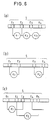
- the longitudinal impedance can be determined either (a) sequentially, (b) on a sample basis or (c) with overlap.
- Fig. 3 MG denotes a reference channel, while the sizes marked by respective distance arrows R1, R2, R3 and R4 indicate changes in impedance in channels 1, 2, 3 and 4.
- the signals R1 to R4 characterize a propulsive contraction wave.
- the passage time or passenger speed in the organ under investigation can be calculated from the transit times between two channels.
- FIG. 4 illustrates further details of a modified embodiment of a catheter for use in accordance with the invention.
- the illustration shows that the catheter tube 2 is closed at the front end 3 in a well rounded manner and is connected to a plug 10 with its internal leads 7.
- the diameter d can be up to a few mm.
- the catheter is flexible, but the measuring part I M of the catheter 1 can be of different flexibility or even rigid, for example by using ceramic materials.
- the length of the measuring part I M and the supply lines I Z can be designed differently with a length of up to a few meters. Due to the tube interior, the catheter can be stiffened temporarily, for example during the measurement.
- the catheter 1 is up to a few (at least three) many (z. B. 32 and more) electrodes 4 (E1, E2, E3, E4, ...) provided.
- the electrodes are electrically conductively connected to the plug 10 of an impedance measuring arrangement 12 via the feed lines 7 and are connected to a display or writing device 18 and / or to a signal processing unit 17 with an associated display device.
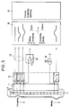
- An example embodiment of the arrangement structure is illustrated in FIG. 5.
- the catheter 1 can be provided with one or more temperature sensors (not shown) along its longitudinal axis.
- the catheter 1 can be used in addition to the impedance measurement and at the same time to record EMG signals that lead to the mechanical contraction of an organ.
- the catheter also allows simultaneous functional electrical stimulation or irritation of the examined organ via the electrodes.
- biosignal transducers 15 for simultaneous recording of electrical biosignals (e.g. EMG, EKG) with channel-provided amplifiers for signal separation or stimulation devices in individual or all channels, e.g. B. current sources 16 for electrical stimulation or elements for pressure absorption or for stimulation with a pressure balloon.
- electrical biosignals e.g. EMG, EKG
- current sources 16 for electrical stimulation or elements for pressure absorption or for stimulation with a pressure balloon.
- the motility and peristalsis processes in healthy as well as diseased organs e.g. B. in the esophagus, in the intestine, in the urether, etc.
- the movement of the contents of these organs is usually one-way, although z. B. in the intestine also numerous mixing processes occur and are known, in which the contents are transported back and forth.
- the contraction processes must be strictly synchronized in order to move the content.
- the decrease or a total failure of the spontaneous activity of even a small section can lead to malfunctions of the entire organ.
Description
Die Erfindung betrifft die Verwendung eines Katheters in Form eines Schlauchs oder Strangs aus einem elektrisch nicht leitenden Kunststoff, der ähnlich wie in US-A-4,706,688 beschrieben, im Meßbereich eine Mehrzahl in definiertem gegenseitigem Abstand angeordnete, den Kunststoffschlauch oder Kunststoffstrang wenigstens teilweise ringförmig umgebende Elektroden trägt, deren Signalzuleitungen oder -ableitungen im Inneren des Schlauchs oder Strangs verlaufen bzw. in diesen eingebettet sind. Die Erfindung bezieht sich weiterhin auf eine Meßvorrichtung unter Verwendung eines solchen Katheters, mit der sich Signale zur Beurteilung von Motilität und/oder Peristaltik gewinnen lassen.The invention relates to the use of a catheter in the form of a tube or strand made of an electrically non-conductive plastic which, similarly to that described in US Pat. No. 4,706,688, has a plurality of electrodes arranged at a defined mutual distance in the measuring range and surrounding the plastic tube or strand at least partially in a ring carries, whose signal leads or leads run inside the hose or strand or are embedded in it. The invention further relates to a measuring device using such a catheter, with which signals for assessing motility and / or peristalsis can be obtained.
Zur Diagnostik von krankheitsbedingten Störungen der Motilität bzw. der Peristaltik stehen heute zwei grundsätzlich unterschiedliche Verfahrensmöglichkeiten zur Verfügung, nämlich
- a) die Manometrie mittels der Perfusionsmeßtechnik oder mittels Halbleiterdruckaufnehmern und
- b) bildgebende Verfahren, die sich entweder der röntgenologischen Darstellung bzw. Szintigraphie der mit Kontrastmitteln versehenen Inhalte bedienen.
- a) the manometry by means of perfusion measurement technology or by means of semiconductor pressure transducers and
- b) imaging processes which either use the radiographic representation or scintigraphy of the contents provided with contrast media.
Bei der Manometrie wird eine Druckänderung zur Charakterisierung der Kontraktionsabläufe in einem schmalen Abschnitt des zu untersuchenden Organs herangezogen. Die größte Verbreitung hat bei dieser Art von Messung die Perfusionsmeßtechnik erfahren. Dabei wird die Druckänderung bestimmt, die sich im Katheter, der mit einem konstanten Flüssigkeitsstrom durchflossen wird, bei Behinderung des Ausflusses durch die Kontraktion eines betreffenden Organs ergibt, gemessen. Da hierbei aber pro Kanal Schläuche mit einem inneren Durchmesser von über 1 mm verwendet werden müssen, ist ein Multikatheter mit bis zu acht Kanälen hinsichtlich seines Durchmessers gerade noch zu akzeptieren. Ein weiterer wichtiger Nachteil ist aber, daß von einem Perfusionskatheter in die Organe Flüssigkeit eingeleitet wird, welche die Funktion des zu messenden Organs gerade bei einer Langzeitmessung wesentlich beeinträchtigen kann.In manometry, a change in pressure is used to characterize the contraction processes in a narrow section of the organ to be examined. The most widespread use of this type of measurement has been perfusion measurement technology. Here the change in pressure is determined, which results in the catheter, through which a constant liquid flow flows, when the outflow is obstructed by the contraction of an organ in question. However, since tubes with an inner diameter of over 1 mm must be used for each channel, a multicatheter with up to eight channels is required barely accept its diameter. Another important disadvantage, however, is that fluid is introduced into the organs from a perfusion catheter, which fluid can significantly impair the function of the organ to be measured, particularly in the case of long-term measurement.
Bildgebende Verfahren sind prinzipiell geeignet, den Nachweis der Motilität beispielsweise in der Speiseröhre zu erbringen. Die Diagnostik im Darmbereich dagegen gestaltet sich wegen der vielen Überlagerungen problematisch. Darüber hinaus muß der hohe Kostenaufwand für die Anschaffung, den Betrieb und nicht zuletzt auch für die Auswertung der gewonnenen Bilder in Betracht gezogen werden.In principle, imaging methods are suitable for proving motility, for example, in the esophagus. The diagnosis in the intestinal area, however, is problematic because of the many overlaps. In addition, the high cost of purchasing, operating and, not least, evaluating the images obtained must be taken into account.
Der Erfindung liegt die Aufgabe zugrunde, ein Verfahren und eine relativ einfach zu realisierende Meßvorrichtung zur Beurteilung von Motilität und/oder Peristaltik in schlauchförmigen, ihren Inhalt transportierenden Organen zu schaffen, das sich universeller einsetzen läßt und zu verläßlichen Diagnoseergebnissen führt.The invention has for its object to provide a method and a relatively easy to implement measuring device for assessing motility and / or peristalsis in tubular organs that transport their contents, which can be used more universally and leads to reliable diagnostic results.
Die Erfindung sieht zur Gewinnung von Signalen zur Beurteilung von Motilität und/oder Peristaltik in schlauchförmigen, ihren Inhalt transportierenden Organen bzw. zur Bestimmung der dynamischen Nachgiebigkeit von schlauchförmigen Leitungsorganen mittels simultaner multipler Impedanzmessung erfindungsgemäß die Verwendung eines im Patentanspruch 1 definierten Katheters vor.The invention provides for the use of a catheter as defined in
Vorteilhafte Weiterbildungen der erfindungsgemäßen Verwendung eines solchen Katheters sind in weiteren Patentansprüchen angegeben und unter anderem in der nachfolgenden Beschreibung erläutert.Advantageous developments of the use of such a catheter according to the invention are specified in further patent claims and explained, inter alia, in the following description.
Eine Meßeinrichtung zur Bestimmung von Motilität und/oder Peristaltik in schlauchförmigen, ihren Inhalt transportierenden Organen unter Verwendung eines derartigen Katheters ist Gegenstand des Patentanspruchs 7 und weiterer abhängiger Patentansprüche.A measuring device for determining motility and / or peristalsis in tubular organs transporting their content using such a catheter is the subject of
Die erfindungsgemäße Verwendung eines solchen Katheter erlaubt es, Signale und Daten zu gewinnen, die zur Beurteilung der Art der Motilität und Peristaltik räumlich und zeitlich dienen, nämlich von stationären, propulsiven, repulsiven Wellen, von Kontraktionsausbreitung usw. Das zugrunde liegende Meßverfahren kann zur Bestimmung von Charakteristika, wie z. B. der Passagezeit und Passagegeschwindigkeit, der Kontraktionsfrequenz und der Kontraktionshäufigkeit einzelner Organabschnitte herangezogen werden.The use of such a catheter according to the invention makes it possible to obtain signals and data which serve for the spatial and temporal assessment of the nature of the motility and peristalsis, namely of stationary, propulsive, repulsive waves, of contraction propagation, etc. The underlying measurement method can be used to determine Characteristics such as B. the passage time and passenger speed, the contraction frequency and the contraction frequency of individual organ sections are used.
Der Katheter wird zur Aufnahme in ein Organ eingeführt und in einer definierten Lage gegen eine Längsverschiebung fixiert. Die zu verwendenden Signale werden durch eine simultane oder quasi simultane Erfassung der Impedanz von mindestens drei bis vielen Kanälen gewonnen, wobei typischerweise 32 und mehr Kanäle verwendet werden.The catheter is inserted into an organ and is fixed in a defined position against longitudinal displacement. The signals to be used are obtained by a simultaneous or quasi-simultaneous detection of the impedance of at least three to many channels , typically 32 and more channels being used.
Vorteilhafte Ausführungsformen der Erfindung sowie weitere Einzelheiten derselben werden nachfolgend unter Bezug auf die Zeichnung in beispielsweiser Ausführungsform näher erläutert. Es zeigen:
- Fig. 1
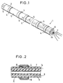
- die vergrößerte perspektivische Darstellung eines Meßbereichabschnitts eines schlauchförmigen Katheters;
- Fig. 2
- eine vergrößerte Ausschnittdarstellung im Längsschnitt durch einen Meßbereich eines Katheters;
- Fig. 3
- veranschaulicht ein Verfahren zur simultanen Registrierung der Speiseröhrenaktivität mit einem multiplen Meßkatheter bei erfindungsgemäßer Art Verwendung;
- Fig. 4
- verdeutlicht auch in Verbindung mit Fig. 3 eine bestimmte Ausführungsform eines Katheters;
- Fig. 5
- ein schematisches Blockschaltbild zur Verdeutlichung eines Meßaufbaus bei erfindungsgemäßer Verwendung eines Katheters; und
- Fig. 6
- verschiedene Möglichkeiten zur schaltungsmäßigen Anordnung einzelner Meßkanäle.
- Fig. 1
- the enlarged perspective view of a measuring section of a tubular catheter;
- Fig. 2
- an enlarged sectional view in longitudinal section through a measuring range of a catheter;
- Fig. 3
- illustrates a method for simultaneous registration of esophageal activity with a multiple measuring catheter in the manner of use according to the invention;
- Fig. 4
- also illustrates in connection with FIG. 3 a specific embodiment of a catheter;
- Fig. 5
- a schematic block diagram to illustrate a measurement setup when using a catheter according to the invention; and
- Fig. 6
- Different possibilities for the circuit-like arrangement of individual measuring channels.
Die Fig. 1 läßt einen Teilabschnitt des Meßbereichs eines schlauchförmigen, vorzugsweise flexiblen Katheters 1 erkennen, der im wesentlichen aus einem Schlauch aus einem elektrisch nicht leitfähigen Kunststoff besteht. Als Materialien kommen hier z. B. Polyurethan, Polyamid, Polyethylen, Polytetrafluorethylen, Polyvinylchlorid oder auch bestimmte Siliconkautschukverbindungen in Frage.1 shows a partial section of the measuring range of a tubular, preferably
Um die Außenseite des Schlauchs 2 sind in ungefähr gleichabständiger, jedoch nicht notwendigerweise gleichabständiger Folge ringförmige Elektroden 4 gelegt, die, wie die Fig. 2 erkennen läßt, aus einem flachen Bandmaterial hergestellt und mit dem Grundkörper des Katheters, also mit dem Schlauch 2, festhaftend verbunden sind. Die Kanten der Elektroden 4 sind abgerundet und so ausgebildet und in das Schlauchmaterial eingelassen, daß es zu keinen Verletzungen kommen kann. Als Materialien für die Elektroden kommen Metalle, Elektrodenmaterialien zweiter Art und leitfähige Kunststoffe in Frage. Wichtige Eigenschaften der Elektroden 4 sind deren Niederohmigkeit geringer Polarisationsspannung in der oberen Elektrodenschicht und ihre Langzeitstabilität. Da eine Elektrode 4 einen Übergang zu einem Elektrolyten bildet, muß sie, um diese geforderten Eigenschaften zu haben, mit einer Schicht 9, z. B. Silber-Silberchlorid, versehen sein. Der Abstand zwischen den Elektroden 4 kann konstant oder nach einem räumlichen Muster ausgebildet sein. Weitere Variablen im Bereich der Elektroden sind deren Breite und der gegenseitige Abstand eines Elektrodenpaars, das bei der Impedanzmessung einem Meßkanal zugeordnet wird. Die Breite der Elektroden 4 kann unterschiedlich ausgebildet sein; sie richtet sich nach dem Durchmesser des Schlauchs 2 und nach den zu messenden Anwendungen.Around the outside of the
Die Elektrodenzuleitungen verlaufen im Inneren des Schlauchs 2 beispielsweise einem separaten Kanal 14, der durch Zwischenwände von weiteren, im Schlauchinneren verlaufenden Einzelkanälen 6 getrennt ist, deren Funktion später erläutert wird. An einer inneren Kontaktstelle 8 ist eine jeweilige Zuleitung 7 mit der zugeordneten Elektrode 4 verbunden.The electrode feed lines run inside the
Der Katheter 1 kann mit einem oder mehreren Lumen 5 versehen werden, durch die an unterschiedlichen Stellen aus dem Organ Stoffe für Analysezwecke entnommen oder Stoffe oder Flüssigkeiten als Kontrastmittel oder zur Funktionsstimulation eingegeben werden können. Eine solche funktionelle Stimulation kann jedoch nicht nur über eine Flüssigkeit, sondern auch elektrisch über die Meßelektroden 4 selbst erfolgen. Darüber hinaus können die Elektroden zur Aufnahme von elektrischen Biosignalen verwendet werden.The
Die Prinzipdarstellung der Fig. 3 verdeutlicht die simultane Registrierung der Speiseröhrenaktivität mit einem multiplen Meßkatheter 1.3 illustrates the simultaneous registration of esophageal activity with a
Ein Meßkanal wird dabei entweder zwischen zwei Elektroden 4 (E₁/E₂ bzw. E₂/E₃ bzw. E₃/E₄) zur Messung der Längsimpedanz oder zwischen einer Elektrode auf dem Katheter 1 und einer zentralen großflächigen Elektrode (nicht dargestellt) auf dem Körper ausgebildet.A measuring channel is either formed between two electrodes 4 (E₁ / E₂ or E₂ / E₃ or E₃ / E₄) for measuring the longitudinal impedance or between an electrode on the
Die Längsimpedanz kann, wie die Fig. 6 verdeutlicht, entweder (a) sequentiell, (b) probenweise oder (c) mit Überlappung ermittelt werden.6 illustrates, the longitudinal impedance can be determined either (a) sequentially, (b) on a sample basis or (c) with overlap.
In der Fig. 3 ist mit MG ein Referenzkanal bezeichnet, während die durch jeweilige Abstandspfeile markierten Größen R₁, R₂, R₃ und R₄ Impedanzveränderungen in den Kanälen 1, 2, 3 und 4 angeben. Im dargestellten Beispiel charakterisieren die Signale R₁ bis R₄ eine propulsive Kontraktionswelle. Aus den Laufzeiten zwischen zwei Kanälen kann die Passagezeit oder Passagegeschwindigkeit im jeweils untersuchten Organ errechnet werden.In Fig. 3 MG denotes a reference channel, while the sizes marked by respective distance arrows R₁, R₂, R₃ and R₄ indicate changes in impedance in
Fig. 4 verdeutlicht weitere Einzelheiten einer abgewandelten Ausführungsform eines Katheters zur erfindungsgemäßen Verwendung. Die Darstellung läßt erkennen, daß der Katheterschlauch 2 am vorderen Ende 3 gut abgerundet verschlossen ist und mit seinen im Inneren verlaufenden Zuleitungen 7 an einen Stecker 10 angeschlossen ist. Der Durchmesser d kann bis zu wenigen mm betragen. Der Katheter ist flexibel, jedoch kann der Meßteil IM des Katheters 1 unterschiedlich flexibel oder sogar starr ausgebildet sein kann, z.B. durch Verwendung von Keramikmaterialien. Die Länge des Meßteils IM und der Zuleitungen IZ können unterschiedlich mit bis zu einigen Metern Länge ausgebildet sein. Aufgrund des Schlauchinnenraums kann der Katheter vorübergehend, beispielsweise während der Messung, versteift werden.4 illustrates further details of a modified embodiment of a catheter for use in accordance with the invention. The illustration shows that the
Der Katheter 1 ist mit wenigen (mindestens drei) bis zu vielen (z. B. 32 und mehr) Elektroden 4 (E₁, E₂, E₃, E₄, ...) versehen. Die Elektroden sind über die Zuleitungen 7 elektrisch leitend mit dem Stecker 10 einer Impedanzmeßanordnung 12 verbunden und auf eine Anzeige- bzw. Schreibeinrichtung 18 und/oder auf eine Signalverarbeitungseinheit 17 mit zugeordneter Anzeigevorrichtung geschaltet. Eine beispielsweise Ausführungsform des Anordnungsaufbaus ist in Fig. 5 veranschaulicht.The
Außer mit den Lumen 5, deren Zweck und Funktion bereits erläutert wurde, kann der Katheter 1 mit einem oder mehreren Temperaturmeßfühlern (nicht dargestellt) entlang seiner Längsachse versehen sein.In addition to the
Der Katheter 1 kann zusätzlich zur Impedanzmessung und gleichzeitig auch zur Aufnahme von EMG-Signalen herangezogen werden, die der mechanischen Kontraktion eines Organs voraneilen.The
Über die Elektroden erlaubt der Katheter auch eine gleichzeitige funktionelle elektrische Stimulation oder Reizung des untersuchten Organs.The catheter also allows simultaneous functional electrical stimulation or irritation of the examined organ via the electrodes.
Darüber hinaus können in den Meßkatheter noch weitere Biosignal-Wandler 15 zur gleichzeitigen Aufnahme von elektrischen Biosignalen (z. B. EMG, EKG) mit kanalweise vorgesehenen Verstärkern zur Signaltrennung oder Stimulationseinrichtungen in einzelnen oder allen Kanälen, z. B. Stromquellen 16 zur elektrischen Stimulation oder Elemente für die Druckaufnahme oder zur Stimulation mit einem Druckballon integriert werden.In addition,
Bei erfindungsgemäßer Verwendung eines Meßkatheters der beschriebenen Art lassen sich die Motilitäts- und Peristaltikabläufe in gesunden wie auch erkrankten Organen, z. B. in der Speiseröhre, im Darm, im Urether, etc. erfassen. Die Fortbewegung der Inhalte dieser Organe Ist in der Regel in eine Richtung orientiert, obwohl z. B. im Darm auch zahlreiche Mischvorgänge vorkommen und bekannt sind, bei denen die Inhalte hin- und hertransportiert werden. Zur Fortbewegung der Inhalte müssen die Kontraktionsabläufe streng synchronisiert werden. Das Nachlassen bzw. ein totales Versagen der Spontanaktivität bereits eines kleinen Abschnitts kann zu Fehlfunktionen des gesamten Organs führen. Mit der hier vorgestellten erfindungsgemäßen Verwendung eines Katheters und der Meßeinrichtung lassen sich die Abschnitte des Organs mit einer fehlerhaften Funktion gut diagnostizieren.When using a measuring catheter of the type described according to the invention, the motility and peristalsis processes in healthy as well as diseased organs, e.g. B. in the esophagus, in the intestine, in the urether, etc. The movement of the contents of these organs is usually one-way, although z. B. in the intestine also numerous mixing processes occur and are known, in which the contents are transported back and forth. The contraction processes must be strictly synchronized in order to move the content. The decrease or a total failure of the spontaneous activity of even a small section can lead to malfunctions of the entire organ. With the use of a catheter and the measuring device according to the invention presented here, the sections of the organ with a faulty function can be diagnosed well.
Neben der Anwendung im medizinischen Bereich ist auch eine technische Anwendung möglich, so z. B. zur Messung der dynamischen Nachgiebigkeit von Schlauchwänden bei Applikation einer Impuls-Druckwelle zur Ermittlung der dynamischen Belastung der Wände. Damit lassen sich altersbedingte Veränderungen einer Schlauchwand rechtzeitig erkennen und beseitigen.In addition to the application in the medical field, a technical application is also possible. B. to measure the dynamic compliance of hose walls when applying a pulse pressure wave to determine the dynamic load on the walls. This enables age-related changes in a hose wall to be recognized and eliminated in good time.
Claims (16)
- Use of a catheter in the form of a tube (2) or cord made of non-electroconductive plastic, which bears in the measuring area a plurality of electrodes (4) arranged at a defined distance from one another and enclosing the plastic tube (2) or plastic cord at least partially in annular fashion, the signal leads to or from which electrodes extend in the interior of the tube (2) or cord in order to obtain signals for evaluating motility and/or peristalsis in tubular organs that transport their contents, or in order to determine the dynamic resilience of tubular conveying organs, by means of simultaneous, multiple impedance measurement.
- Use according to Claim 1, characterized in that the catheter, in the case of a plastic tube (2), is closed at the front end (3).
- Use according to Claim 1, characterized in that the plastic tube (2) or plastic cord of the catheter is provided at the front end with a probe.
- Use according to Claim 1 or 3, characterized in that the plastic tube (2) or plastic cord of the catheter is provided at the front end with a device for specific organ stimulation.
- Use according to one of the preceding claims, characterized in that the plastic tube (2) or plastic cord of the catheter is provided at the front end with a device for fixing the catheter to the inner wall of the organ, for example by means of suction.
- Use according to one of the preceding claims, characterized in that the plastic tube (2) or plastic cord of the catheter is flexible.
- Measuring device for determining motility and/or peristalsis in tubular organs that transport their contents, with a catheter in the form of a tube (2) or cord made of non-electroconductive plastic, which bears in the measuring area a plurality of electrodes (4) arranged at a defined distance from one another and enclosing the plastic tube (2) or plastic cord at least partially in annular fashion, the signal leads (7) to or from which electrodes extend in the interior of the tube (2) or cord or are embedded therein, characterized by a multi-channel impedance voltage transformer (12) which is connected to the signal leads (7) from the catheter and the signal outputs (13) of which are connected to a multi-channel display or multi-channel recorder (14) and/or to a signal-detecting device (17).
- Measuring device according to Claim 7, characterized in that the plastic tube (2) or plastic cord is essentially rigid in the measuring area.
- Measuring device according to Claim 8, characterized in that the plastic tube (2) or plastic cord contains ceramic material in the measuring area.
- Measuring device according to Claim 8, characterized in that the plastic tube (2) is divided into a plurality of axial longitudinal channels (6), in one of which the signal leads to and from the electrodes extend, while the other longitudinal channels (5) open into openings (5) of the outer tube wall or of the catheter probe.
- Measuring device according to Claim 10, characterized in that the openings (5) in the tube wall have defined distances from one another in the longitudinal direction of the tube (2) and are preferably arranged in the region between two electrodes (4).
- Measuring device according to Claim 8, characterized in that the annular electrodes (4) are made of a strip material with good electroconductivity and/or additionally have on the outside a long-term stable surface coating with high electrolytic conductivity and low polarization voltage.
- Measuring device according to Claim 8, characterized in that the electrodes (4) have different widths in the longitudinal direction of the plastic tube (2) or plastic cord.
- Measuring device according to Claim 8, characterized in that the distance of the electrodes (4) from one another is approximately equal.
- Measuring device according to Claim 8, characterized in that the distance of the electrodes (4) from one another is different in at least one part of the plastic tube (2) or plastic cord from that in another part thereof.
- Measuring device in a measuring unit according to Claim 7, characterized by a device for the simultaneous reception of electrical biosignals (EMG, ECG etc.) by means of individual bio-amplifiers (15) with signal separation.
Applications Claiming Priority (2)
| Application Number | Priority Date | Filing Date | Title |
|---|---|---|---|
| DE3836349A DE3836349A1 (en) | 1988-10-25 | 1988-10-25 | CATHETER FOR MEASURING MOTILITY AND PERISTALTICS IN HOSE-SHAPED ORGANS WHICH CONTAIN THEIR CONTENT BY SIMULTANEOUS MULTIPLE IMPEDANCE MEASUREMENT |
| DE3836349 | 1988-10-25 |
Publications (2)
| Publication Number | Publication Date |
|---|---|
| EP0366127A1 EP0366127A1 (en) | 1990-05-02 |
| EP0366127B1 true EP0366127B1 (en) | 1996-05-08 |
Family
ID=6365892
Family Applications (1)
| Application Number | Title | Priority Date | Filing Date |
|---|---|---|---|
| EP89119860A Expired - Lifetime EP0366127B1 (en) | 1988-10-25 | 1989-10-25 | Use of a catheter and measuring device for measuring the motility and the peristaltic in tubular body parts by means of simultaneous measurement of a plurality of impedances |
Country Status (4)
| Country | Link |
|---|---|
| US (1) | US5109870A (en) |
| EP (1) | EP0366127B1 (en) |
| CA (1) | CA2001503C (en) |
| DE (2) | DE3836349A1 (en) |
Cited By (1)
| Publication number | Priority date | Publication date | Assignee | Title |
|---|---|---|---|---|
| US9763767B2 (en) | 2010-10-13 | 2017-09-19 | Michael T. Abramson | System and method for alleviating sleep apnea |
Families Citing this family (95)
| Publication number | Priority date | Publication date | Assignee | Title |
|---|---|---|---|---|
| DE3836349A1 (en) * | 1988-10-25 | 1990-05-03 | Forschungsgesellschaft Fuer Bi | CATHETER FOR MEASURING MOTILITY AND PERISTALTICS IN HOSE-SHAPED ORGANS WHICH CONTAIN THEIR CONTENT BY SIMULTANEOUS MULTIPLE IMPEDANCE MEASUREMENT |
| GB2254253A (en) * | 1991-04-05 | 1992-10-07 | Deborah Jill Colson | A combined naso-gastric feeding tube and electrode |
| DE4137303C2 (en) * | 1991-11-13 | 1993-12-02 | Rheintechnik Weiland & Kaspar | Process for measuring the electrical conductivity of body fluids, as well as the related measuring probe |
| US5699796A (en) * | 1993-01-29 | 1997-12-23 | Cardima, Inc. | High resolution intravascular signal detection |
| GB9213379D0 (en) * | 1992-06-24 | 1992-08-05 | Smiths Industries Plc | Medico-surgical devices |
| US5341807A (en) * | 1992-06-30 | 1994-08-30 | American Cardiac Ablation Co., Inc. | Ablation catheter positioning system |
| US5292344A (en) * | 1992-07-10 | 1994-03-08 | Douglas Donald D | Percutaneously placed electrical gastrointestinal pacemaker stimulatory system, sensing system, and pH monitoring system, with optional delivery port |
| US5566096A (en) * | 1992-11-13 | 1996-10-15 | Quinton Electrophysiology Corporation | Integrated electrical signal switching and amplifying system |
| US5335668A (en) * | 1993-04-30 | 1994-08-09 | Medical Scientific, Inc. | Diagnostic impedance measuring system for an insufflation needle |
| US5479935A (en) * | 1993-10-21 | 1996-01-02 | Synectics Medical, Inc. | Ambulatory reflux monitoring system |
| US6322518B1 (en) * | 1993-12-06 | 2001-11-27 | Heska Corporation | Method and apparatus for measuring cardiac output |
| US6438400B1 (en) | 1993-12-06 | 2002-08-20 | Heska Corporation | Electrode for evaluating cardiac functions via esophagus |
| WO1995020344A1 (en) * | 1994-01-28 | 1995-08-03 | Ep Technologies, Inc. | System for examining cardiac tissue electrical characteristics |
| US5485849A (en) * | 1994-01-31 | 1996-01-23 | Ep Technologies, Inc. | System and methods for matching electrical characteristics and propagation velocities in cardiac tissue |
| WO1995020348A1 (en) * | 1994-01-28 | 1995-08-03 | Ep Technologies, Inc. | Matching electrical characteristics and propagation velocities to locate ablation sites |
| US5494042A (en) * | 1994-01-28 | 1996-02-27 | Ep Technologies, Inc. | Systems and methods for deriving electrical characteristics of cardiac tissue for output in iso-characteristic displays |
| US5487391A (en) * | 1994-01-28 | 1996-01-30 | Ep Technologies, Inc. | Systems and methods for deriving and displaying the propagation velocities of electrical events in the heart |
| US5577509A (en) * | 1994-01-28 | 1996-11-26 | Ep Technologies, Inc. | Systems and methods for examining the electrical characteristics and timing of electrical events in cardiac tissue |
| NL9401180A (en) | 1994-07-18 | 1996-03-01 | Draeger Med Electronics Bv | Catheter with multiple sensors at a distance from each other. |
| US5533515A (en) * | 1994-08-11 | 1996-07-09 | Foster-Miller | Solid state sphincter myometers |
| US5617876A (en) * | 1994-09-19 | 1997-04-08 | Les Enterprises Laborie, Inc. | Apparatus for examining the functioning of body structures comprising smooth muscle walls |
| AR004329A1 (en) * | 1995-11-28 | 1998-11-04 | Abbott Lab | ARRANGEMENT FOR ENTERAL FEEDING INCLUDING A FEEDING TUBE THAT HAS A PROXIMAL END AND A DISTAL END. |
| NO304404B1 (en) * | 1996-04-02 | 1998-12-14 | Egidija R Nilsen | EMG sensor and multi-channel urethral EMG sensor system |
| DE19701840A1 (en) * | 1996-05-21 | 1997-11-27 | Ruesch Willy Ag | Ureteral catheter |
| US5924984A (en) * | 1997-01-30 | 1999-07-20 | University Of Iowa Research Foundation | Anorectal probe apparatus having at least one muscular activity sensor |
| US6259938B1 (en) | 1998-05-15 | 2001-07-10 | Respironics, Inc. | Monitoring catheter and method of using same |
| IL126727A (en) | 1998-10-22 | 2006-12-31 | Given Imaging Ltd | Method for delivering a device to a target location |
| IL129508A (en) * | 1999-04-19 | 2006-12-31 | Medisense Technologies Interna | System for detecting smooth muscle motor activity and method therefor |
| US6351665B1 (en) | 1999-05-07 | 2002-02-26 | Kenneth L Koch | Method and apparatus for evaluating myoelectric signals and identifying artifact |
| US7140766B2 (en) * | 1999-08-04 | 2006-11-28 | Given Imaging Ltd. | Device, system and method for temperature sensing in an in-vivo device |
| DE60141044D1 (en) * | 2000-01-19 | 2010-02-25 | Given Imaging Ltd | SYSTEM FOR DETECTING SUBSTANCES |
| IL163684A0 (en) * | 2000-05-31 | 2005-12-18 | Given Imaging Ltd | Measurement of electrical characteristics of tissue |
| US7052474B2 (en) * | 2000-10-02 | 2006-05-30 | Sandhill Scientific, Inc. | Pharyngoesophageal monitoring systems |
| ATE404114T1 (en) * | 2001-06-18 | 2008-08-15 | Given Imaging Ltd | SWALLOWABLE IN-VIVO CAPSULE WITH A CIRCUIT BOARD HAVING RIGID AND FLEXIBLE SECTIONS |
| US7160258B2 (en) * | 2001-06-26 | 2007-01-09 | Entrack, Inc. | Capsule and method for treating or diagnosing the intestinal tract |
| WO2003051194A1 (en) * | 2001-12-18 | 2003-06-26 | 3Cpm Company | Endoscopic measurement of myoelectrical activity from intra-abdominal organs |
| AUPS226502A0 (en) * | 2002-05-13 | 2002-06-13 | Advanced Metal Coatings Pty Limited | A multi-electrode lead |
| AU2003225331B2 (en) * | 2002-05-13 | 2008-05-15 | Cathrx Ltd | A multi-electrode lead |
| US7662094B2 (en) * | 2002-05-14 | 2010-02-16 | Given Imaging Ltd. | Optical head assembly with dome, and device for use thereof |
| WO2004014227A1 (en) * | 2002-08-13 | 2004-02-19 | Given Imaging Ltd. | System for in vivo sampling and analysis |
| WO2004028336A2 (en) * | 2002-09-30 | 2004-04-08 | Given Imaging Ltd. | Reduced size imaging device |
| AU2003269438A1 (en) * | 2002-09-30 | 2004-04-19 | Given Imaging Ltd. | In-vivo sensing system |
| AT413189B (en) * | 2002-10-07 | 2005-12-15 | Cnsystems Medizintechnik Gmbh | MEDICAL ELECTRODE ELEMENT |
| US7783345B2 (en) * | 2002-10-07 | 2010-08-24 | Cnsystems Medizintechnik Gmbh | Impedance-based measuring method for hemodynamic parameters |
| WO2004036803A2 (en) * | 2002-10-15 | 2004-04-29 | Given Imaging Ltd. | Device, system and method for transfer of signals to a moving device |
| US20080045788A1 (en) * | 2002-11-27 | 2008-02-21 | Zvika Gilad | Method and device of imaging with an in vivo imager |
| EP1576530A4 (en) * | 2002-12-26 | 2009-03-25 | Given Imaging Ltd | In vivo imaging device and method of manufacture thereof |
| WO2004058041A2 (en) * | 2002-12-26 | 2004-07-15 | Given Imaging Ltd. | Immobilizable in vivo sensing device |
| GB2397231A (en) * | 2003-01-18 | 2004-07-21 | Ep Advance Ltd | Feeding tube or catheter having internal conductors connected to external moulded annular electrodes |
| WO2004069032A2 (en) * | 2003-01-29 | 2004-08-19 | Sandhill Scientific, Inc. | Viscous swallow medium and method of use for esophageal function testing |
| AU2004260579A1 (en) * | 2003-08-04 | 2005-02-10 | Ditens A/S | Apparatus for detecting axial force in the digestive system |
| US20050080832A1 (en) * | 2003-09-05 | 2005-04-14 | Stuebe Thomas D. | Esophageal waveform analysis for detection and quantification of reflux episodes |
| DE102004017397A1 (en) * | 2004-04-08 | 2005-11-03 | Schönfeld, Andreas, Dipl.-Ing. | Sensor for detecting myoelectric signals |
| SE0401151D0 (en) * | 2004-05-04 | 2004-05-04 | Benf Ab | Arrangement and method for assessing the motility of a generally tubular anatomical organ |
| US7643865B2 (en) * | 2004-06-30 | 2010-01-05 | Given Imaging Ltd. | Autonomous in-vivo device |
| US20060015013A1 (en) * | 2004-06-30 | 2006-01-19 | Zvika Gilad | Device and method for in vivo illumination |
| US7596403B2 (en) | 2004-06-30 | 2009-09-29 | Given Imaging Ltd. | System and method for determining path lengths through a body lumen |
| GB0419238D0 (en) * | 2004-08-28 | 2004-09-29 | Univ Manchester | Dysphagia recovery |
| AU2005229684A1 (en) * | 2004-11-04 | 2006-05-18 | Given Imaging Ltd | Apparatus and method for receiving device selection and combining |
| US20060169294A1 (en) * | 2004-12-15 | 2006-08-03 | Kaler Karan V | Inertial navigation method and apparatus for wireless bolus transit monitoring in gastrointestinal tract |
| US7407503B2 (en) * | 2004-12-21 | 2008-08-05 | Ethicon Endo-Surgey, Inc. | Medical-treatment electrode assembly having treatment-monitoring application |
| US8235055B2 (en) | 2005-01-11 | 2012-08-07 | Uti Limited Partnership | Magnetic levitation of intraluminal microelectronic capsule |
| US8738106B2 (en) * | 2005-01-31 | 2014-05-27 | Given Imaging, Ltd | Device, system and method for in vivo analysis |
| US8852083B2 (en) * | 2005-02-04 | 2014-10-07 | Uti Limited Partnership | Self-stabilized encapsulated imaging system |
| US20060231110A1 (en) * | 2005-03-24 | 2006-10-19 | Mintchev Martin P | Ingestible capsule for esophageal monitoring |
| IL174531A0 (en) * | 2005-04-06 | 2006-08-20 | Given Imaging Ltd | System and method for performing capsule endoscopy diagnosis in remote sites |
| US7610093B2 (en) * | 2005-04-28 | 2009-10-27 | Medtronic, Inc. | Implantable optical pressure sensor for sensing urinary sphincter pressure |
| US8068910B2 (en) * | 2005-04-28 | 2011-11-29 | Medtronic, Inc. | Flexible tube sensor for sensing urinary sphincter pressure |
| AT502921B1 (en) | 2005-10-21 | 2012-01-15 | Falko Dr Skrabal | DEVICE FOR MEASURING HEART AND VESSEL FUNCTION (FUNCTION) AND BODY SPACES (SPACES) BY MEANS OF IMPEDANCE MEASUREMENT |
| US7896805B2 (en) * | 2005-11-23 | 2011-03-01 | Given Imaging Ltd. | In-vivo imaging device and optical system thereof |
| WO2007063550A2 (en) * | 2005-12-02 | 2007-06-07 | Given Imaging Ltd. | System and device for in vivo procedures |
| US20070156051A1 (en) * | 2005-12-29 | 2007-07-05 | Amit Pascal | Device and method for in-vivo illumination |
| US9320417B2 (en) | 2005-12-29 | 2016-04-26 | Given Imaging Ltd. | In-vivo optical imaging device with backscatter blocking |
| US20070167834A1 (en) * | 2005-12-29 | 2007-07-19 | Amit Pascal | In-vivo imaging optical device and method |
| JP2009532168A (en) * | 2006-04-03 | 2009-09-10 | ギブン イメージング リミテッド | Apparatus, system and method for in vivo analysis |
| DE102008026898A1 (en) * | 2008-06-05 | 2009-12-17 | Standard Instruments Gmbh | Diagnostic system |
| US8515507B2 (en) * | 2008-06-16 | 2013-08-20 | Given Imaging Ltd. | Device and method for detecting in-vivo pathology |
| CZ302036B6 (en) * | 2008-12-08 | 2010-09-15 | Hanzalová@Jitka | Catheter for measuring electrochemical properties of body fluids |
| US8516691B2 (en) | 2009-06-24 | 2013-08-27 | Given Imaging Ltd. | Method of assembly of an in vivo imaging device with a flexible circuit board |
| US20120184866A1 (en) * | 2009-09-29 | 2012-07-19 | St. Jude Medical Ab | Implantable medical device and method for multisite measurement of intracardiac impedance |
| US9814408B2 (en) * | 2010-07-13 | 2017-11-14 | Diversatek Healthcare, Inc. | Display system for displaying conditions of esophageal mucosa and indications of gastroesophageal reflux disease |
| US20140058282A1 (en) * | 2010-10-18 | 2014-02-27 | Mayo Foundation For Medical Education And Research | System and method for gastro-intestinal electrical activity |
| GB201105622D0 (en) | 2011-04-01 | 2011-05-18 | Phangenesis Ltd | Multi functional catheter |
| US10456060B2 (en) * | 2012-02-22 | 2019-10-29 | Ghassan S. Kassab | Devices for detecting organ contents using impedance and methods of using the same to provide various therapies |
| US8700133B2 (en) | 2012-06-18 | 2014-04-15 | Smart Iv Llc | Apparatus and method for monitoring catheter insertion |
| US9597482B2 (en) | 2012-06-18 | 2017-03-21 | Smart Iv Llc | Apparatus and method for monitoring catheter insertion |
| CH708172B1 (en) * | 2013-05-30 | 2021-02-15 | Unisensor Ag | Sphincter testing catheter. |
| CN103479354B (en) * | 2013-09-30 | 2015-05-20 | 上海交通大学 | In-vivo biological tissue compound conductivity minimally-invasive measuring probe based on four-electrode measurement method |
| US20150126837A1 (en) * | 2013-11-01 | 2015-05-07 | Ghassan S. Kassab | Devices, systems, and methods to determine volume reflux |
| CN103654769B (en) * | 2013-12-25 | 2016-04-27 | 张强 | A kind of esophageal lead electrode fixing device |
| GB2532044A (en) | 2014-11-06 | 2016-05-11 | Phagenesis Ltd | Catheter for recovery of dysphagia |
| DE102016113657A1 (en) | 2016-07-25 | 2018-01-25 | Standard Instruments Gmbh | Diagnostic system |
| US11291382B2 (en) | 2018-06-01 | 2022-04-05 | Diversatek Healthcare, Inc. | System and method for detecting and measuring the condition of intraluminal esophageal mucosa |
| US11712566B2 (en) | 2019-08-12 | 2023-08-01 | Alimetry Limited | Sacral nerve stimulation |
| WO2022120462A1 (en) * | 2020-12-10 | 2022-06-16 | Mirshekari Gholamreza | Imaging catheter using electrical properties of tissues |
Citations (1)
| Publication number | Priority date | Publication date | Assignee | Title |
|---|---|---|---|---|
| US5109870A (en) * | 1988-10-25 | 1992-05-05 | Forschungsgesellschaft Fur Biomedizinische Technik E.V. | Apparatus for and method of motility and peristalsis monitoring |
Family Cites Families (16)
| Publication number | Priority date | Publication date | Assignee | Title |
|---|---|---|---|---|
| US3480003A (en) * | 1967-02-03 | 1969-11-25 | Battelle Development Corp | Apparatus for measuring esophageal motility |
| US4073287A (en) * | 1976-04-05 | 1978-02-14 | American Medical Systems, Inc. | Urethral profilometry catheter |
| CA1065969A (en) * | 1977-09-28 | 1979-11-06 | Gratien Bouillon | Self-blocking cerebral catheter |
| US4706688A (en) * | 1981-05-18 | 1987-11-17 | Don Michael T Anthony | Non-invasive cardiac device |
| US4450527A (en) * | 1982-06-29 | 1984-05-22 | Bomed Medical Mfg. Ltd. | Noninvasive continuous cardiac output monitor |
| DD210175A3 (en) * | 1982-09-28 | 1984-05-30 | Pkm Anlagenbau Veb | PROCESS FOR FILLING AND / OR REMOVING LIQUID GAS FROM PACKAGING |
| DE3300765C1 (en) * | 1983-01-12 | 1983-10-20 | Ingeborg Nieß Elektromedizinische Apparate, 7906 Blaustein | Electrode device for the reduction of electro-physiological voltages |
| US4503859A (en) * | 1983-06-16 | 1985-03-12 | William Beaumont Hospital | Esophageal function and EKG monitor |
| US4561450A (en) * | 1984-10-03 | 1985-12-31 | The United States Of America As Represented By The Secretary Of The Army | Electrolytic pressure transduction system |
| US4721115A (en) * | 1986-02-27 | 1988-01-26 | Cardiac Pacemakers, Inc. | Diagnostic catheter for monitoring cardiac output |
| US4836214A (en) * | 1986-12-01 | 1989-06-06 | Bomed Medical Manufacturing, Ltd. | Esophageal electrode array for electrical bioimpedance measurement |
| US4898176A (en) * | 1988-06-22 | 1990-02-06 | The Cleveland Clinic Foundation | Continuous cardiac output by impedance measurements in the heart |
| US5025786A (en) * | 1988-07-21 | 1991-06-25 | Siegel Sharon B | Intracardiac catheter and method for detecting and diagnosing myocardial ischemia |
| US4887610A (en) * | 1988-10-19 | 1989-12-19 | University Of Virginia Alumni Patents Foundation | Device to measure electrical and mechanical events in the human sphincters |
| US4960133A (en) * | 1988-11-21 | 1990-10-02 | Brunswick Manufacturing Co., Inc. | Esophageal electrode |
| US4911174A (en) * | 1989-02-13 | 1990-03-27 | Cardiac Pacemakers, Inc. | Method for matching the sense length of an impedance measuring catheter to a ventricular chamber |
-
1988
- 1988-10-25 DE DE3836349A patent/DE3836349A1/en not_active Withdrawn
-
1989
- 1989-10-25 CA CA002001503A patent/CA2001503C/en not_active Expired - Lifetime
- 1989-10-25 EP EP89119860A patent/EP0366127B1/en not_active Expired - Lifetime
- 1989-10-25 DE DE58909675T patent/DE58909675D1/en not_active Expired - Lifetime
-
1990
- 1990-10-26 US US07/604,355 patent/US5109870A/en not_active Expired - Lifetime
Patent Citations (1)
| Publication number | Priority date | Publication date | Assignee | Title |
|---|---|---|---|---|
| US5109870A (en) * | 1988-10-25 | 1992-05-05 | Forschungsgesellschaft Fur Biomedizinische Technik E.V. | Apparatus for and method of motility and peristalsis monitoring |
Cited By (1)
| Publication number | Priority date | Publication date | Assignee | Title |
|---|---|---|---|---|
| US9763767B2 (en) | 2010-10-13 | 2017-09-19 | Michael T. Abramson | System and method for alleviating sleep apnea |
Also Published As
| Publication number | Publication date |
|---|---|
| EP0366127A1 (en) | 1990-05-02 |
| US5109870A (en) | 1992-05-05 |
| CA2001503A1 (en) | 1990-04-25 |
| DE3836349A1 (en) | 1990-05-03 |
| CA2001503C (en) | 1995-12-05 |
| DE58909675D1 (en) | 1996-06-13 |
Similar Documents
| Publication | Publication Date | Title |
|---|---|---|
| EP0366127B1 (en) | Use of a catheter and measuring device for measuring the motility and the peristaltic in tubular body parts by means of simultaneous measurement of a plurality of impedances | |
| Henderson et al. | An impedance camera for spatially specific measurements of the thorax | |
| US6882879B2 (en) | Impedance spectroscopy system and catheter for ischemic mucosal damage monitoring in hollow viscous organs | |
| Silny | Intraluminal multiple electric impedance procedure for measurement of gastrointestinal motility | |
| DE3629587C2 (en) | ||
| US5919142A (en) | Electrical impedance tomography method and apparatus | |
| US20100210958A1 (en) | System, method and device for monitoring the condition of an internal organ | |
| US9055875B2 (en) | Method and apparatus for measuring activity in the peripheral nervous system | |
| DE102011101580B4 (en) | Sensor device for the electromyographic derivation of muscle signals as well as methods for the preparation of an electromyographic derivation of muscle signals and system | |
| DE2758347A1 (en) | ARRANGEMENT FOR DETECTING A BASELINE SHIFT OF AN ECG SIGNAL | |
| DE2726630A1 (en) | METHOD AND DEVICE FOR THE INVESTIGATION OF INTERNAL PHYSIOLOGICAL PROCEDURES | |
| DE60320315T2 (en) | DEVICE FOR MEASURING PRINTING PROFILES | |
| DE3421045A1 (en) | Device for controlling NMR imaging by organ movements | |
| DE102010006969A1 (en) | Gastroscope for examining gastric acid and tissue of stomach lining with Helicobacter pylori infection of upper gastro intestinal tract of patient, has sensor including electrodes, where electrical voltage is applied between electrodes | |
| EP0340774A2 (en) | Method and means to measure the electrodermal reactions | |
| DE102008026898A1 (en) | Diagnostic system | |
| WO2016138541A1 (en) | Esophageal distensibility testing using electrical impedance | |
| DE19952820C2 (en) | Arrangement for time and location resolved impedance spectroscopy in expandable hollow organs | |
| DE69929092T2 (en) | SENSOR FOR MEASURING THE BLOOD OF THE TISSUE | |
| Sadleir et al. | Inflatable belt for the application of electrode arrays | |
| DE1498612C (en) | Measuring probe for examinations inside the body with an electrochemical measuring cell A.nm Beckman Instruments Ine, Fullertone Calif (V St A) | |
| DE10305537A1 (en) | Catheter based device for characterizing the wall, contents and their transport in hollow organs, e.g. in diagnosis of the gastrointestinal tract, the urethra or blood vessels by making electrical measurement using electrode pairs | |
| Wenzl | Esophageal Intraluminal Impedance | |
| DE102015007875A1 (en) | Measuring arrangement and method for in-vivo determination of the lactate concentration in blood by means of electrochemical impedance spectroscopy | |
| DE102016113657A1 (en) | Diagnostic system |
Legal Events
| Date | Code | Title | Description |
|---|---|---|---|
| PUAI | Public reference made under article 153(3) epc to a published international application that has entered the european phase |
Free format text: ORIGINAL CODE: 0009012 |
|
| AK | Designated contracting states |
Kind code of ref document: A1 Designated state(s): BE CH DE FR GB IT LI |
|
| 17P | Request for examination filed |
Effective date: 19900507 |
|
| 17Q | First examination report despatched |
Effective date: 19920605 |
|
| GRAH | Despatch of communication of intention to grant a patent |
Free format text: ORIGINAL CODE: EPIDOS IGRA |
|
| GRAA | (expected) grant |
Free format text: ORIGINAL CODE: 0009210 |
|
| STAA | Information on the status of an ep patent application or granted ep patent |
Free format text: STATUS: THE PATENT HAS BEEN GRANTED |
|
| AK | Designated contracting states |
Kind code of ref document: B1 Designated state(s): BE CH DE FR GB IT LI |
|
| PG25 | Lapsed in a contracting state [announced via postgrant information from national office to epo] |
Ref country code: BE Effective date: 19960508 |
|
| REG | Reference to a national code |
Ref country code: CH Ref legal event code: NV Representative=s name: A. KERR AG PATENTANWAELTE |
|
| REF | Corresponds to: |
Ref document number: 58909675 Country of ref document: DE Date of ref document: 19960613 |
|
| GBT | Gb: translation of ep patent filed (gb section 77(6)(a)/1977) |
Effective date: 19960607 |
|
| ITF | It: translation for a ep patent filed |
Owner name: ING. C. GREGORJ S.P.A. |
|
| ET | Fr: translation filed | ||
| PLBE | No opposition filed within time limit |
Free format text: ORIGINAL CODE: 0009261 |
|
| 26N | No opposition filed | ||
| REG | Reference to a national code |
Ref country code: GB Ref legal event code: IF02 |
|
| REG | Reference to a national code |
Ref country code: CH Ref legal event code: PFA Owner name: FORSCHUNGSGESELLSCHAFT FUER BIOMEDIZINISCHE TECHN Free format text: FORSCHUNGSGESELLSCHAFT FUER BIOMEDIZINISCHE TECHNIK E.V.#PAUWELSSTRASSE 30#D-52074 AACHEN (DE) -TRANSFER TO- FORSCHUNGSGESELLSCHAFT FUER BIOMEDIZINISCHE TECHNIK E.V.#PAUWELSSTRASSE 30#D-52074 AACHEN (DE) |
|
| PGFP | Annual fee paid to national office [announced via postgrant information from national office to epo] |
Ref country code: CH Payment date: 20081027 Year of fee payment: 20 Ref country code: DE Payment date: 20081028 Year of fee payment: 20 |
|
| PGFP | Annual fee paid to national office [announced via postgrant information from national office to epo] |
Ref country code: IT Payment date: 20081028 Year of fee payment: 20 |
|
| PGFP | Annual fee paid to national office [announced via postgrant information from national office to epo] |
Ref country code: FR Payment date: 20081021 Year of fee payment: 20 |
|
| PGFP | Annual fee paid to national office [announced via postgrant information from national office to epo] |
Ref country code: GB Payment date: 20081024 Year of fee payment: 20 |
|
| REG | Reference to a national code |
Ref country code: CH Ref legal event code: PL |
|
| REG | Reference to a national code |
Ref country code: GB Ref legal event code: PE20 Expiry date: 20091024 |
|
| PG25 | Lapsed in a contracting state [announced via postgrant information from national office to epo] |
Ref country code: GB Free format text: LAPSE BECAUSE OF EXPIRATION OF PROTECTION Effective date: 20091024 |