EP0366381B1 - Signal identification system - Google Patents
Signal identification system Download PDFInfo
- Publication number
- EP0366381B1 EP0366381B1 EP89310876A EP89310876A EP0366381B1 EP 0366381 B1 EP0366381 B1 EP 0366381B1 EP 89310876 A EP89310876 A EP 89310876A EP 89310876 A EP89310876 A EP 89310876A EP 0366381 B1 EP0366381 B1 EP 0366381B1
- Authority
- EP
- European Patent Office
- Prior art keywords
- code
- signal
- frequency bands
- given signal
- sequence
- Prior art date
- Legal status (The legal status is an assumption and is not a legal conclusion. Google has not performed a legal analysis and makes no representation as to the accuracy of the status listed.)
- Expired - Lifetime
Links
Images


Classifications
-
- H—ELECTRICITY
- H04—ELECTRIC COMMUNICATION TECHNIQUE
- H04H—BROADCAST COMMUNICATION
- H04H20/00—Arrangements for broadcast or for distribution combined with broadcast
- H04H20/28—Arrangements for simultaneous broadcast of plural pieces of information
- H04H20/30—Arrangements for simultaneous broadcast of plural pieces of information by a single channel
- H04H20/31—Arrangements for simultaneous broadcast of plural pieces of information by a single channel using in-band signals, e.g. subsonic or cue signal
-
- G—PHYSICS
- G11—INFORMATION STORAGE
- G11B—INFORMATION STORAGE BASED ON RELATIVE MOVEMENT BETWEEN RECORD CARRIER AND TRANSDUCER
- G11B20/00—Signal processing not specific to the method of recording or reproducing; Circuits therefor
- G11B20/00086—Circuits for prevention of unauthorised reproduction or copying, e.g. piracy
- G11B20/00884—Circuits for prevention of unauthorised reproduction or copying, e.g. piracy involving a watermark, i.e. a barely perceptible transformation of the original data which can nevertheless be recognised by an algorithm
- G11B20/00891—Circuits for prevention of unauthorised reproduction or copying, e.g. piracy involving a watermark, i.e. a barely perceptible transformation of the original data which can nevertheless be recognised by an algorithm embedded in audio data
Definitions
- This invention relates to signal identification systems.
- the invention relates to systems in which a code is superimposed on a signal so as to enable the subsequent identification of the signal.
- Such systems have particular application in, for example, the recording industry for providing information on a sound recording so as to identify the origin of the recording, the owner of the copyright in the recording, or whether any copyright royalties are due.
- EP 0245037 there is described a system for producing an identification code on a sound track recording, the system including an encoder circuit effective to eliminate two predetermined frequency bands from an audio signal to form notches in the signal.
- the encoder circuit inserts a signal in the form of a suitable identification code sequence into these notches, the code signal consisting of pulses at the centre frequencies of the notches, one value of each digit of the code sequence being represented by one of the frequencies and a different value of each digit being represented by the other frequency.
- the present invention provides a signal identification system comprising: encoding means including filter means for eliminating from a given signal a plurality of predetermined frequency bands within the bandwidth of the given signal to form corresponding notches in the bandwidth of the given signal, and means for inserting a sequence of code signals within the notches; and decoding means for determining whether the sequence of code signals is present in the given signal, characterized in that the filter means is controllable to selectively eliminate a subset of the plurality of predetermined frequency bands from the given signal at any given time, which subset is selectable from a plurality of such subsets which differ from each other in that at least one said frequency band is substituted by another said frequency band, the filter means being provided with control means for selecting a plurality of said subsets in succession.
- any attempt by a defrauder to remove or interfere with all possible notch frequency bands simultaneously will result in significant distortion of the audio signal as the notch frequency bands may be spread over a wide range of the signal spectrum. Whilst it may be possible to detect the presence of individual notches and filter out the data within each notch frequency band, this would require sophisticated signal processing means beyond the abilities of at least the average home copier. Furthermore as the notches may move around the signal spectrum in a pseudo-random manner, the presence of the code will be more difficult to detect, either audibly where the signal is an audio signal, or using electronic test gear.
- the invention also provides a system for incorporating a code into a given signal, comprising filter means for eliminating from the given signal a plurality of predetermined frequency bands within the bandwidth of the given signal to form corresponding notches in the bandwidth of the given signal, and means for inserting a sequence of code signals within the notches, characterized in that the filter means is controllable to selectively eliminate a subset of the plurality of predetermined frequency bands from the given signal at any given time, which subset is selectable from a plurality of such subsets which differ from each other in that at least one said frequency band is substituted by another said frequency band, the filter means being provided with control means for selecting a plurality of said subsets in succession.
- the invention also provides a system for decoding a given signal which has had a code incorporated therein by such a system, which decoding system has an input for said given signal and comprises a respective decoder corresponding to each selected subset, each decoder having an input coupled to the system input and being arranged to selectively decode any of the code signals which are present within its input signal within the corresponding subset of the plurality of frequency bands, and code recognition means coupled to outputs of the decoders for recognizing said code upon its decoding by any said decoder.
- the system to be described is designed to produce identification coding signals on a high fidelity musical sound track, and is an adaptation of the system described in Applicant's copending European patent Application EP 0245037.
- the system to be described is designed to use code signals incorporated within a choice of three different combinations of pairs of notch frequency bands, chosen from a total of six different notch frequency bands within the frequency spectrum of the musical track.
- the six frequency bands are positioned, as shown in figure 1, midway between each of the musical notes E3 to A3#. There are thus 15 possible combinations of pairs of frequency bands.
- the number of allowable combinations is restricted to three i.e. the pairs A, B and C indicated in the figure. It will be seen that it is the minimum number of combinations which ensures that each notch frequency band is used at least once.
- a random sequence generator 201 is used to choose in which of the possible combinations A, B, C of the pairs of frequency bands the coding signal is to lie, and operates two switches 203, 205 accordingly.
- a filter coefficients store 207 acting under the control of the random sequence generator 201 loads an appropriate software signal into appropriate digital signal processing (DSP) chips in an encoder 209 to program two notch filters, indicated as 301 and 303 in Figure 3, at the respective appropriate centre of the chosen frequency band frequencies ie 2713Hz and 3228Hz in the case of pair A.
- the filter coefficients store 207 is also effective to program a masking filter, indicated as 305 in Figure 3.
- a code frequency generator 211 also responsive to the random sequence generator 201, generates binary coding pulses at the centre frequencies of the two notch filters 301, 303, the 2713Hz pulses representing a space or zero in each data bit of the coding signal and the 3228Hz pulses representing a mark or one in each data bit, or vice versa, in the case where pair A is chosen.
- each audio signal channel is applied, via an analogue to digital converter 307 if the audio signal is not already a digital signal, to the notch filters 301, 303.
- the digitised audio signal is also applied to a control branch of the encoder including the masking filter 305, the output of the masking filter 305 being applied via a rectifier 309 to a multiplier 311 to which the output of the code generator 211 is also applied.
- the output of the multiplier 311 is connected to an adder 313, which in use of the encoder produces the required coded audio signal via a digital to analogue converter 315.
- the notch filters 301, 303 produce a sequence of notches in the audio signal, at the frequency bands determined by the random sequence generator 201, each notch being encoded with the appropriate code signal at the appropriate frequency as described in more detail in European Patent Application EP 0245037.
- the control branch including the masking filter 305 ensures that the amplitude of the code signal will not be determined by the amplitude of the audio signal at frequencies, either high or low, which do not adequately mask the code signal.
- the multiplier 311 ensures that the amplitude of the code signals may be kept at a fixed level below the amplitude of the audio signal.
- each decoder 401, 403, 405 is identical and is of the form shown in Figure 5.
- each channel of the encoded stereo signal is separately filtered within each decoder 401, 403, 405 by an initial bandpass filter 501, 502 effective to isolate the code frequencies from the stereo signal.
- An automatic gain controller unit 503, 504 adjusts the amplitude of the code signals to a uniform level.
- the difference between outputs of the units 503, 504 is then produced at subtractor 505 to provide a signal incorporating the full 32 bit code plus any preamble.
- the 2713 Hz "space data bit” and 3227 Hz “mark data bit” signals are then separated by means of appropriate band pass filters 507, 509, and rectified by respective rectifiers 511, 513.
- the bandwidth of the filters 507, 509 will generally be made wider than the notches formed in the audio signal to allow for speed variation in the reproducing equipment. This will allow some programme breakthrough into the code demodulation, thus resulting in occasional code mutilation. This is overcome by combining the complementary code sequences produced by the rectifiers 511, 513 in both an adder 515 and a subtractor 517.
- the output of the subtractor 517 should, therefore produce a double amplitude code signal, with the output of the adder 515 being zero in the absence of programme breakthrough, any programme breakthrough thus being detectable and compensatable for.
- the outputs of the three decoders 401, 403, 405 are monitored by a suitable code recognition means 407, such that when a valid code signal is produced it is identified and displayed on a suitable code display means, for example a VDU or a printer.
- the code recognition means 407 will also be effective to recognise and compensate for any programme breakthrough.
- the outputs from the decoder system will be examined in the code recognition means 407 to check that the expected pattern of code sequences is present, or whether there has been any attempt to remove the code.
- the decoder system must decode signals from all the available combinations of two notches provided by the total number of notch frequencies in use, using fast DSP integrated circuits it will be possible to implement several decoding units within one DSP chip, all responsive to the same coded audio signal input, but examining different notch combinations.
- the decoder system does not require any knowledge of the sequence in which the notch frequencies are generated by the random sequence generator 201. The provision of such knowledge would, however, enable the decoder system to be simplified.
- FIG. 6 An example of a more sophisticated encoder is shown in Figure 6, in which corresponding features to those shown in the encoder of Figure 3 and the decoder of Figure 5 are correspondingly labelled, and both right and left stereo channels are shown.
- the encoder shown in Figure 6 incorporates a code truncation means effective to prevent insertion of the code in an audio signal if the content of the signal is not suitable to allow insertion of a complete code sequence, or if it appears that the code would not be successfully decoded.
- the encoder thus incorporates delay means 611, 613, 615, 617 effective to produce a delay of for example approximately one second in the audio signal path.
- a level checking section 619 to monitor the audio signal derived from the left and right notched input signals via a decoder section incorporating bandpass filters 507, 509 respectively set at the appropriate upper and lower notch frequency bands, and rectifiers 511, 513 together with suitable adders and subtractors 505, 515, 517 as shown.
- Respective automatic gain control units 503, 504 are provided in respect of each channel, these being effective to constantly change the gain of the masked music signal path, such that if it is well coded the code would remain at a constant level.
- the level checking section 619 thus ensures that if the amplitude of the code is so low as to be unrecoverable in a particular section of the audio signal, the code will not be inserted.
- the interference from the audio signal is also checked to ensure that the code will not be severely corrupted.
- the code generator 211 is thus responsive to an enable signal from the level checking system, so as to generate complete code sequences if the audio signal remains suitable for the duration of a sequence.
- the timing of the system is arranged such that as the code sequence ends, the start of that same sequence will be emerging from the delay units 611, 613, 615, 617.
- the coded signal is then cross-faded via cross fade units 619, 621 under the control of the code generator 211 to the output for the duration of the sequence.
- each coding signal is inserted in the incoming signal at two different frequencies
- the invention is also applicable to signal coding systems in which the code is inserted in the signal at a single frequency, e.g. as described in US Patent No. 3845391.
Abstract
Description
- This invention relates to signal identification systems. In particular the invention relates to systems in which a code is superimposed on a signal so as to enable the subsequent identification of the signal. Such systems have particular application in, for example, the recording industry for providing information on a sound recording so as to identify the origin of the recording, the owner of the copyright in the recording, or whether any copyright royalties are due.
- In our copending European patent application EP 0245037 there is described a system for producing an identification code on a sound track recording, the system including an encoder circuit effective to eliminate two predetermined frequency bands from an audio signal to form notches in the signal. The encoder circuit inserts a signal in the form of a suitable identification code sequence into these notches, the code signal consisting of pulses at the centre frequencies of the notches, one value of each digit of the code sequence being represented by one of the frequencies and a different value of each digit being represented by the other frequency.
- Using such a system it is possible to insert an identification code into a high fidelity audio signal in such a way that the code is inaudible but is recoverable, using either digital or analogue techniques. The system does, however, have a potential security problem in that it would be possible for a potential defrauder such as a home-copier to filter out the code signal by the use of narrow notch filters operating at the same frequencies as used in the original encoding process. Whilst this would not produce any significant degradation to the audio quality, the code would then be undetectable.
- It is an object of the present invention to provide a system which is suitable for producing an identification code on a sound track recording wherein it is more difficult to filter out the code signal without degradation of the audio signal.
- According to a first aspect, the present invention provides a signal identification system comprising: encoding means including filter means for eliminating from a given signal a plurality of predetermined frequency bands within the bandwidth of the given signal to form corresponding notches in the bandwidth of the given signal, and means for inserting a sequence of code signals within the notches; and decoding means for determining whether the sequence of code signals is present in the given signal, characterized in that the filter means is controllable to selectively eliminate a subset of the plurality of predetermined frequency bands from the given signal at any given time, which subset is selectable from a plurality of such subsets which differ from each other in that at least one said frequency band is substituted by another said frequency band, the filter means being provided with control means for selecting a plurality of said subsets in succession.
- Thus in a system in accordance with the invention, any attempt by a defrauder to remove or interfere with all possible notch frequency bands simultaneously will result in significant distortion of the audio signal as the notch frequency bands may be spread over a wide range of the signal spectrum. Whilst it may be possible to detect the presence of individual notches and filter out the data within each notch frequency band, this would require sophisticated signal processing means beyond the abilities of at least the average home copier. Furthermore as the notches may move around the signal spectrum in a pseudo-random manner, the presence of the code will be more difficult to detect, either audibly where the signal is an audio signal, or using electronic test gear.
- The invention also provides a system for incorporating a code into a given signal, comprising filter means for eliminating from the given signal a plurality of predetermined frequency bands within the bandwidth of the given signal to form corresponding notches in the bandwidth of the given signal, and means for inserting a sequence of code signals within the notches, characterized in that the filter means is controllable to selectively eliminate a subset of the plurality of predetermined frequency bands from the given signal at any given time, which subset is selectable from a plurality of such subsets which differ from each other in that at least one said frequency band is substituted by another said frequency band, the filter means being provided with control means for selecting a plurality of said subsets in succession.
- The invention also provides a system for decoding a given signal which has had a code incorporated therein by such a system, which decoding system has an input for said given signal and comprises a respective decoder corresponding to each selected subset, each decoder having an input coupled to the system input and being arranged to selectively decode any of the code signals which are present within its input signal within the corresponding subset of the plurality of frequency bands, and code recognition means coupled to outputs of the decoders for recognizing said code upon its decoding by any said decoder.
- A signal identification system in accordance with the invention will now be described, by way of example only, with reference to the accompanying drawings in which:-
- Figure 1 shows a selection of six possible notch frequency bands for use in a stereo musical recording signal;
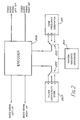
- Figure 2 is a schematic block diagram of an encoding apparatus for the system;
- Figure 3 is a more detailed schematic block diagram of part of the encoding apparatus of figure 2;
- Figure 4 is a schematic block diagram of a decoding system.
- Figure 5 is a more detailed schematic diagram of one of the decoders shown in Figure 4; and
- Figure 6 is a schematic block diagram of an alternative encoding apparatus to that shown in Figure 3.
- The system to be described is designed to produce identification coding signals on a high fidelity musical sound track, and is an adaptation of the system described in Applicant's copending European patent Application EP 0245037.
- Referring firstly to Figure 1, the system to be described is designed to use code signals incorporated within a choice of three different combinations of pairs of notch frequency bands, chosen from a total of six different notch frequency bands within the frequency spectrum of the musical track. The six frequency bands are positioned, as shown in figure 1, midway between each of the musical notes E3 to A3#. There are thus 15 possible combinations of pairs of frequency bands. In order to simplify the system however, in particular reduce the number of decoders which will ultimately be required to decode the coded audio signal, in the particular example being described, the number of allowable combinations is restricted to three i.e. the pairs A, B and C indicated in the figure. It will be seen that it is the minimum number of combinations which ensures that each notch frequency band is used at least once.
- Referring now also to Figures 2 and 3, in which corresponding components are correspondingly labelled, a
random sequence generator 201 is used to choose in which of the possible combinations A, B, C of the pairs of frequency bands the coding signal is to lie, and operates twoswitches filter coefficients store 207 acting under the control of therandom sequence generator 201 loads an appropriate software signal into appropriate digital signal processing (DSP) chips in anencoder 209 to program two notch filters, indicated as 301 and 303 in Figure 3, at the respective appropriate centre of the chosen frequency band frequencies ie 2713Hz and 3228Hz in the case of pair A. Thefilter coefficients store 207 is also effective to program a masking filter, indicated as 305 in Figure 3. Acode frequency generator 211, also responsive to therandom sequence generator 201, generates binary coding pulses at the centre frequencies of the twonotch filters - Referring now particularly to Figure 3 which illustrates only the left hand audio signal encoder, the right hand audio signal encoder being of equivalent construction, in use of the encoder system each audio signal channel is applied, via an analogue to
digital converter 307 if the audio signal is not already a digital signal, to thenotch filters masking filter 305, the output of themasking filter 305 being applied via arectifier 309 to amultiplier 311 to which the output of thecode generator 211 is also applied. The output of themultiplier 311 is connected to anadder 313, which in use of the encoder produces the required coded audio signal via a digital toanalogue converter 315. - Thus in use of the encoding system the
notch filters random sequence generator 201, each notch being encoded with the appropriate code signal at the appropriate frequency as described in more detail in European Patent Application EP 0245037. The control branch including themasking filter 305 ensures that the amplitude of the code signal will not be determined by the amplitude of the audio signal at frequencies, either high or low, which do not adequately mask the code signal. Themultiplier 311 ensures that the amplitude of the code signals may be kept at a fixed level below the amplitude of the audio signal. - Turning now to Figures 4 and 5, in order to decode the signal, it is necessary to provide three
decoders decoder decoder initial bandpass filter gain controller unit units subtractor 505 to provide a signal incorporating the full 32 bit code plus any preamble. The 2713 Hz "space data bit" and 3227 Hz "mark data bit" signals are then separated by means of appropriateband pass filters respective rectifiers filters rectifiers adder 515 and asubtractor 517. The output of thesubtractor 517 should, therefore produce a double amplitude code signal, with the output of theadder 515 being zero in the absence of programme breakthrough, any programme breakthrough thus being detectable and compensatable for. Referring now again to Figure 4 the outputs of the threedecoders - It will be appreciated that whilst the decoder system must decode signals from all the available combinations of two notches provided by the total number of notch frequencies in use, using fast DSP integrated circuits it will be possible to implement several decoding units within one DSP chip, all responsive to the same coded audio signal input, but examining different notch combinations. By implementing the decoder system so as to examine simultaneously all known possible notch combinations, the decoder system does not require any knowledge of the sequence in which the notch frequencies are generated by the
random sequence generator 201. The provision of such knowledge would, however, enable the decoder system to be simplified. - It will be appreciated that, whilst in the signal coding system described herebefore by way of example there are only three possible combinations of notch frequencies, i.e. A, B, C, in practice a larger number of combinations may be used, although this will generally lead to a more complex decoder system. In the case of the
encoder 209 however, as this is implemented by means of DSP chips, only one pair ofnotch filters masking filter 305 will be required per channel of the audio signal. Thus any required sequence of notch frequencies may be produced merely by software implementation. It will be appreciated however that whilst it is particularly advantageous to implement a system in accordance with the invention in digital form, it is also possible to implement the system in analogue form. - It will be appreciated that further levels of sophistication may be incorporated in a system in accordance with the invention. An example of a more sophisticated encoder is shown in Figure 6, in which corresponding features to those shown in the encoder of Figure 3 and the decoder of Figure 5 are correspondingly labelled, and both right and left stereo channels are shown. The encoder shown in Figure 6 incorporates a code truncation means effective to prevent insertion of the code in an audio signal if the content of the signal is not suitable to allow insertion of a complete code sequence, or if it appears that the code would not be successfully decoded. The encoder thus incorporates delay means 611, 613, 615, 617 effective to produce a delay of for example approximately one second in the audio signal path. This delay enables a
level checking section 619 to monitor the audio signal derived from the left and right notched input signals via a decoder section incorporatingbandpass filters rectifiers subtractors gain control units level checking section 619 thus ensures that if the amplitude of the code is so low as to be unrecoverable in a particular section of the audio signal, the code will not be inserted. The interference from the audio signal is also checked to ensure that the code will not be severely corrupted. Thecode generator 211 is thus responsive to an enable signal from the level checking system, so as to generate complete code sequences if the audio signal remains suitable for the duration of a sequence. The timing of the system is arranged such that as the code sequence ends, the start of that same sequence will be emerging from thedelay units cross fade units code generator 211 to the output for the duration of the sequence. - It will also be appreciated that whilst it is particularly advantageous for each coding signal to be inserted in the incoming signal at two different frequencies, the invention is also applicable to signal coding systems in which the code is inserted in the signal at a single frequency, e.g. as described in US Patent No. 3845391.
Claims (8)
- A signal identification system comprising:
encoding means including filter means (203, 207, 301, 303) for eliminating from a given signal a plurality of predetermined frequency bands within the bandwidth of the given signal to form corresponding notches in the bandwidth of the given signal, and means (205, 211, 311, 313) for inserting a sequence of code signals within the notches; and
decoding means (401 - 409; 501 - 517) for determining whether the sequence of code signals is present in the given signal,
characterized in that the filter means (203, 207, 301, 303) is controllable to selectively eliminate a subset of the plurality of predetermined frequency bands from the given signal at any given time, which subset is selectable from a plurality of such subsets which differ from each other in that at least one said frequency band is substituted by another said frequency band, the filter means (203, 207, 301, 303) being provided with control means (201) for selecting a plurality of said subsets in succession. - A system according to Claim 1, wherein the plurality of predetermined frequency bands consists of at least three predetermined frequency bands and wherein the control means (201) is arranged to select a subset containing two of these bands each time.
- A system as claimed in Claim 2, wherein the means (205, 211, 311, 313) for inserting a sequence of code signals within the notches is arranged to insert code signals in a complementary manner into the two notches formed at any given time.
- A system according to Claim 1, Claim 2 or Claim 3, wherein the decoding means (401 - 409) includes means (401, 403, 405) for simultaneously inspecting all the frequency bands of the given signal which are included in the selected subsets for the presence of the sequence of code signals therein.
- A system for incorporating a code into a given signal, comprising filter means (203, 207, 301, 303) for eliminating from the given signal a plurality of predetermined frequency bands within the bandwidth of the given signal to form corresponding notches in the bandwidth of the given signal, and means (205, 211, 311, 313) for inserting a sequence of code signals within the notches, characterized in that the filter means (203, 207, 301, 303) is controllable to selectively eliminate a subset of the plurality of predetermined frequency bands from the given signal at any given time, which subset is selectable from a plurality of such subsets which differ from each other in that at least one said frequency band is substituted by another said frequency band, the filter means (203, 207, 301, 303) being provided with control means (201) for selecting a plurality of said subsets in succession.
- A system according to Claim 5, wherein the plurality of predetermined frequency bands consists of at least three predetermined frequency bands and wherein the control means (201) is arranged to select a subset containing two of these bands each time.
- A system as claimed in Claim 6, wherein the means (205, 211, 311, 313) for inserting a sequence of code signals within the notches is arranged to insert code signals in a complementary manner into the two notches formed at any given time.
- A system for decoding a given signal which has had a code incorporated therein by a system as claimed in Claim 5, which decoding system has an input for said given signal and comprises a respective decoder (401, 403, 405) corresponding to each selected subset, each decoder having an input coupled to the system input and being arranged to selectively decode any of the code signals which are present within its input signal within the corresponding subset of the plurality of frequency bands, and code recognition means (407) coupled to outputs of the decoders (401, 403, 405) for recognizing said code upon its decoding by any said decoder (401, 403, 405).
Applications Claiming Priority (2)
| Application Number | Priority Date | Filing Date | Title |
|---|---|---|---|
| GB888824969A GB8824969D0 (en) | 1988-10-25 | 1988-10-25 | Identification codes |
| GB8824969 | 1988-10-25 |
Publications (3)
| Publication Number | Publication Date |
|---|---|
| EP0366381A2 EP0366381A2 (en) | 1990-05-02 |
| EP0366381A3 EP0366381A3 (en) | 1991-09-25 |
| EP0366381B1 true EP0366381B1 (en) | 1995-03-15 |
Family
ID=10645756
Family Applications (1)
| Application Number | Title | Priority Date | Filing Date |
|---|---|---|---|
| EP89310876A Expired - Lifetime EP0366381B1 (en) | 1988-10-25 | 1989-10-23 | Signal identification system |
Country Status (6)
| Country | Link |
|---|---|
| US (1) | US5113437A (en) |
| EP (1) | EP0366381B1 (en) |
| JP (1) | JP3212988B2 (en) |
| AT (1) | ATE120059T1 (en) |
| DE (1) | DE68921692T2 (en) |
| GB (1) | GB8824969D0 (en) |
Cited By (3)
| Publication number | Priority date | Publication date | Assignee | Title |
|---|---|---|---|---|
| US6754377B2 (en) | 1995-05-08 | 2004-06-22 | Digimarc Corporation | Methods and systems for marking printed documents |
| US7756290B2 (en) | 2000-01-13 | 2010-07-13 | Digimarc Corporation | Detecting embedded signals in media content using coincidence metrics |
| US8204222B2 (en) | 1993-11-18 | 2012-06-19 | Digimarc Corporation | Steganographic encoding and decoding of auxiliary codes in media signals |
Families Citing this family (161)
| Publication number | Priority date | Publication date | Assignee | Title |
|---|---|---|---|---|
| US5434948A (en) * | 1989-06-15 | 1995-07-18 | British Telecommunications Public Limited Company | Polyphonic coding |
| FR2681997A1 (en) * | 1991-09-30 | 1993-04-02 | Arbitron Cy | METHOD AND DEVICE FOR AUTOMATICALLY IDENTIFYING A PROGRAM COMPRISING A SOUND SIGNAL |
| GB2292506B (en) * | 1991-09-30 | 1996-05-01 | Arbitron Company The | Method and apparatus for automatically identifying a program including a sound signal |
| US5319735A (en) * | 1991-12-17 | 1994-06-07 | Bolt Beranek And Newman Inc. | Embedded signalling |
| US6301369B2 (en) | 1992-07-31 | 2001-10-09 | Digimarc Corporation | Image marking to permit later identification |
| US5721788A (en) | 1992-07-31 | 1998-02-24 | Corbis Corporation | Method and system for digital image signatures |
| ES2229214T3 (en) * | 1992-11-16 | 2005-04-16 | Arbitron Inc. | METHOD AND APPARATUS FOR CODING / DECODING BROADCASTED OR RECORDED SEGMENTS AND TO MONITOR THE EXHIBITION OF THE HEARING TO THEM. |
| US6983051B1 (en) * | 1993-11-18 | 2006-01-03 | Digimarc Corporation | Methods for audio watermarking and decoding |
| US7313251B2 (en) * | 1993-11-18 | 2007-12-25 | Digimarc Corporation | Method and system for managing and controlling electronic media |
| US5636292C1 (en) * | 1995-05-08 | 2002-06-18 | Digimarc Corp | Steganography methods employing embedded calibration data |
| US6611607B1 (en) | 1993-11-18 | 2003-08-26 | Digimarc Corporation | Integrating digital watermarks in multimedia content |
| US6580819B1 (en) | 1993-11-18 | 2003-06-17 | Digimarc Corporation | Methods of producing security documents having digitally encoded data and documents employing same |
| US6516079B1 (en) | 2000-02-14 | 2003-02-04 | Digimarc Corporation | Digital watermark screening and detecting strategies |
| US7171016B1 (en) | 1993-11-18 | 2007-01-30 | Digimarc Corporation | Method for monitoring internet dissemination of image, video and/or audio files |
| US6408082B1 (en) | 1996-04-25 | 2002-06-18 | Digimarc Corporation | Watermark detection using a fourier mellin transform |
| US5832119C1 (en) | 1993-11-18 | 2002-03-05 | Digimarc Corp | Methods for controlling systems using control signals embedded in empirical data |
| DE69434237T2 (en) | 1993-11-18 | 2005-12-08 | Digimarc Corp., Tualatin | Video with hidden in-band digital data |
| US5862260A (en) | 1993-11-18 | 1999-01-19 | Digimarc Corporation | Methods for surveying dissemination of proprietary empirical data |
| US5748783A (en) * | 1995-05-08 | 1998-05-05 | Digimarc Corporation | Method and apparatus for robust information coding |
| US6122403A (en) | 1995-07-27 | 2000-09-19 | Digimarc Corporation | Computer system linked by using information in data objects |
| US5822436A (en) | 1996-04-25 | 1998-10-13 | Digimarc Corporation | Photographic products and methods employing embedded information |
| US6757406B2 (en) | 1993-11-18 | 2004-06-29 | Digimarc Corporation | Steganographic image processing |
| US6424725B1 (en) | 1996-05-16 | 2002-07-23 | Digimarc Corporation | Determining transformations of media signals with embedded code signals |
| US5748763A (en) * | 1993-11-18 | 1998-05-05 | Digimarc Corporation | Image steganography system featuring perceptually adaptive and globally scalable signal embedding |
| US5841978A (en) | 1993-11-18 | 1998-11-24 | Digimarc Corporation | Network linking method using steganographically embedded data objects |
| US5768426A (en) * | 1993-11-18 | 1998-06-16 | Digimarc Corporation | Graphics processing system employing embedded code signals |
| US5841886A (en) | 1993-11-18 | 1998-11-24 | Digimarc Corporation | Security system for photographic identification |
| US6522770B1 (en) | 1999-05-19 | 2003-02-18 | Digimarc Corporation | Management of documents and other objects using optical devices |
| US6968057B2 (en) * | 1994-03-17 | 2005-11-22 | Digimarc Corporation | Emulsion products and imagery employing steganography |
| GB2325827B (en) * | 1994-03-31 | 1999-01-27 | Ceridian Corp | Apparatus and method for including codes in audio signals |
| US5450490A (en) * | 1994-03-31 | 1995-09-12 | The Arbitron Company | Apparatus and methods for including codes in audio signals and decoding |
| PL177808B1 (en) * | 1994-03-31 | 2000-01-31 | Arbitron Co | Apparatus for and methods of including codes into audio signals and decoding such codes |
| US5530751A (en) * | 1994-06-30 | 1996-06-25 | Hewlett-Packard Company | Embedded hidden identification codes in digital objects |
| US6560349B1 (en) | 1994-10-21 | 2003-05-06 | Digimarc Corporation | Audio monitoring using steganographic information |
| US7724919B2 (en) * | 1994-10-21 | 2010-05-25 | Digimarc Corporation | Methods and systems for steganographic processing |
| DE19539538A1 (en) * | 1994-10-31 | 1996-05-02 | Tektronix Inc | Inaudible insertion of information into an audio signal |
| US7362775B1 (en) * | 1996-07-02 | 2008-04-22 | Wistaria Trading, Inc. | Exchange mechanisms for digital information packages with bandwidth securitization, multichannel digital watermarks, and key management |
| GB9500285D0 (en) * | 1995-01-07 | 1995-03-01 | Central Research Lab Ltd | A method of labelling an audio signal |
| US7486799B2 (en) * | 1995-05-08 | 2009-02-03 | Digimarc Corporation | Methods for monitoring audio and images on the internet |
| US6721440B2 (en) | 1995-05-08 | 2004-04-13 | Digimarc Corporation | Low visibility watermarks using an out-of-phase color |
| US6760463B2 (en) | 1995-05-08 | 2004-07-06 | Digimarc Corporation | Watermarking methods and media |
| US6728390B2 (en) | 1995-05-08 | 2004-04-27 | Digimarc Corporation | Methods and systems using multiple watermarks |
| US7224819B2 (en) | 1995-05-08 | 2007-05-29 | Digimarc Corporation | Integrating digital watermarks in multimedia content |
| US5613004A (en) | 1995-06-07 | 1997-03-18 | The Dice Company | Steganographic method and device |
| US6411725B1 (en) * | 1995-07-27 | 2002-06-25 | Digimarc Corporation | Watermark enabled video objects |
| US6829368B2 (en) | 2000-01-26 | 2004-12-07 | Digimarc Corporation | Establishing and interacting with on-line media collections using identifiers in media signals |
| US6408331B1 (en) | 1995-07-27 | 2002-06-18 | Digimarc Corporation | Computer linking methods using encoded graphics |
| US6788800B1 (en) | 2000-07-25 | 2004-09-07 | Digimarc Corporation | Authenticating objects using embedded data |
| US6577746B1 (en) | 1999-12-28 | 2003-06-10 | Digimarc Corporation | Watermark-based object linking and embedding |
| US6154484A (en) * | 1995-09-06 | 2000-11-28 | Solana Technology Development Corporation | Method and apparatus for embedding auxiliary data in a primary data signal using frequency and time domain processing |
| US5937000A (en) * | 1995-09-06 | 1999-08-10 | Solana Technology Development Corporation | Method and apparatus for embedding auxiliary data in a primary data signal |
| US5822360A (en) * | 1995-09-06 | 1998-10-13 | Solana Technology Development Corporation | Method and apparatus for transporting auxiliary data in audio signals |
| US5687191A (en) * | 1995-12-06 | 1997-11-11 | Solana Technology Development Corporation | Post-compression hidden data transport |
| US5719937A (en) * | 1995-12-06 | 1998-02-17 | Solana Technology Develpment Corporation | Multi-media copy management system |
| US6466209B1 (en) * | 1995-12-07 | 2002-10-15 | Ncr Corporation | Method for transparent marking of digital images for storage, retrieval and processing within a computer database |
| US7664263B2 (en) | 1998-03-24 | 2010-02-16 | Moskowitz Scott A | Method for combining transfer functions with predetermined key creation |
| US6205249B1 (en) * | 1998-04-02 | 2001-03-20 | Scott A. Moskowitz | Multiple transform utilization and applications for secure digital watermarking |
| US5901178A (en) * | 1996-02-26 | 1999-05-04 | Solana Technology Development Corporation | Post-compression hidden data transport for video |
| GB9604659D0 (en) * | 1996-03-05 | 1996-05-01 | Central Research Lab Ltd | Audio signal identification |
| US20030056103A1 (en) * | 2000-12-18 | 2003-03-20 | Levy Kenneth L. | Audio/video commerce application architectural framework |
| US7715446B2 (en) * | 1996-04-25 | 2010-05-11 | Digimarc Corporation | Wireless methods and devices employing plural-bit data derived from audio information |
| US6381341B1 (en) * | 1996-05-16 | 2002-04-30 | Digimarc Corporation | Watermark encoding method exploiting biases inherent in original signal |
| US7177429B2 (en) | 2000-12-07 | 2007-02-13 | Blue Spike, Inc. | System and methods for permitting open access to data objects and for securing data within the data objects |
| US7457962B2 (en) * | 1996-07-02 | 2008-11-25 | Wistaria Trading, Inc | Optimization methods for the insertion, protection, and detection of digital watermarks in digitized data |
| US7346472B1 (en) * | 2000-09-07 | 2008-03-18 | Blue Spike, Inc. | Method and device for monitoring and analyzing signals |
| US7159116B2 (en) * | 1999-12-07 | 2007-01-02 | Blue Spike, Inc. | Systems, methods and devices for trusted transactions |
| US7107451B2 (en) * | 1996-07-02 | 2006-09-12 | Wistaria Trading, Inc. | Optimization methods for the insertion, protection, and detection of digital watermarks in digital data |
| US5889868A (en) * | 1996-07-02 | 1999-03-30 | The Dice Company | Optimization methods for the insertion, protection, and detection of digital watermarks in digitized data |
| US6078664A (en) * | 1996-12-20 | 2000-06-20 | Moskowitz; Scott A. | Z-transform implementation of digital watermarks |
| US7095874B2 (en) | 1996-07-02 | 2006-08-22 | Wistaria Trading, Inc. | Optimization methods for the insertion, protection, and detection of digital watermarks in digitized data |
| US7730317B2 (en) | 1996-12-20 | 2010-06-01 | Wistaria Trading, Inc. | Linear predictive coding implementation of digital watermarks |
| JP3269014B2 (en) * | 1996-12-25 | 2002-03-25 | 日本アイ・ビー・エム株式会社 | Data hiding method and system using statistical properties |
| GB9700854D0 (en) * | 1997-01-16 | 1997-03-05 | Scient Generics Ltd | Sub-audible acoustic data transmission mechanism |
| US6675383B1 (en) * | 1997-01-22 | 2004-01-06 | Nielsen Media Research, Inc. | Source detection apparatus and method for audience measurement |
| AUPO521897A0 (en) * | 1997-02-20 | 1997-04-11 | Telstra R & D Management Pty Ltd | Invisible digital watermarks |
| US5940429A (en) * | 1997-02-25 | 1999-08-17 | Solana Technology Development Corporation | Cross-term compensation power adjustment of embedded auxiliary data in a primary data signal |
| JP3690043B2 (en) * | 1997-03-03 | 2005-08-31 | ソニー株式会社 | Audio information transmission apparatus and method, and audio information recording apparatus |
| US6427012B1 (en) * | 1997-05-19 | 2002-07-30 | Verance Corporation | Apparatus and method for embedding and extracting information in analog signals using replica modulation |
| US5940135A (en) * | 1997-05-19 | 1999-08-17 | Aris Technologies, Inc. | Apparatus and method for encoding and decoding information in analog signals |
| DE69823640T2 (en) * | 1997-10-02 | 2005-04-28 | Sony Corp. | RECORDING / PLAYING DEVICE AND RECORDING / REPLAYING METHOD |
| JP3737614B2 (en) * | 1997-10-09 | 2006-01-18 | 株式会社ビデオリサーチ | Broadcast confirmation system using audio signal, and audio material production apparatus and broadcast confirmation apparatus used in this system |
| US6804376B2 (en) | 1998-01-20 | 2004-10-12 | Digimarc Corporation | Equipment employing watermark-based authentication function |
| US6773547B2 (en) * | 1998-05-08 | 2004-08-10 | American Air Liquide, Inc. | Process for the bleaching of low consistency pulp using high partial pressure ozone |
| BR9810699A (en) | 1998-05-12 | 2000-09-05 | Nielsen Media Res Inc | Television audience measurement system, process and device to identify a television program selected by a viewer, and software agent stored in memory in association with digital television equipment |
| US7644282B2 (en) | 1998-05-28 | 2010-01-05 | Verance Corporation | Pre-processed information embedding system |
| US7006555B1 (en) | 1998-07-16 | 2006-02-28 | Nielsen Media Research, Inc. | Spectral audio encoding |
| US6272176B1 (en) * | 1998-07-16 | 2001-08-07 | Nielsen Media Research, Inc. | Broadcast encoding system and method |
| GB2342548B (en) | 1998-10-02 | 2003-05-07 | Central Research Lab Ltd | Apparatus for,and method of,encoding a signal |
| US7664264B2 (en) | 1999-03-24 | 2010-02-16 | Blue Spike, Inc. | Utilizing data reduction in steganographic and cryptographic systems |
| US6871180B1 (en) | 1999-05-25 | 2005-03-22 | Arbitron Inc. | Decoding of information in audio signals |
| GB9917985D0 (en) | 1999-07-30 | 1999-09-29 | Scient Generics Ltd | Acoustic communication system |
| US7475246B1 (en) | 1999-08-04 | 2009-01-06 | Blue Spike, Inc. | Secure personal content server |
| US6631165B1 (en) * | 1999-09-01 | 2003-10-07 | Northrop Grumman Corporation | Code modulation using narrow spectral notching |
| CA2809775C (en) * | 1999-10-27 | 2017-03-21 | The Nielsen Company (Us), Llc | Audio signature extraction and correlation |
| US20010040979A1 (en) * | 1999-12-31 | 2001-11-15 | Clay Davidson | Compensating for color response and transfer function of scanner and/or printer when reading a digital watermark |
| GB2358999A (en) * | 2000-02-02 | 2001-08-08 | Central Research Lab Ltd | A system and method for labelling a signal |
| US6625297B1 (en) | 2000-02-10 | 2003-09-23 | Digimarc Corporation | Self-orienting watermarks |
| US6737957B1 (en) | 2000-02-16 | 2004-05-18 | Verance Corporation | Remote control signaling using audio watermarks |
| US7046808B1 (en) * | 2000-03-24 | 2006-05-16 | Verance Corporation | Method and apparatus for detecting processing stages applied to a signal |
| US6968564B1 (en) | 2000-04-06 | 2005-11-22 | Nielsen Media Research, Inc. | Multi-band spectral audio encoding |
| US6804377B2 (en) | 2000-04-19 | 2004-10-12 | Digimarc Corporation | Detecting information hidden out-of-phase in color channels |
| US7466742B1 (en) * | 2000-04-21 | 2008-12-16 | Nielsen Media Research, Inc. | Detection of entropy in connection with audio signals |
| US6879652B1 (en) | 2000-07-14 | 2005-04-12 | Nielsen Media Research, Inc. | Method for encoding an input signal |
| US20040243540A1 (en) * | 2000-09-07 | 2004-12-02 | Moskowitz Scott A. | Method and device for monitoring and analyzing signals |
| US6674876B1 (en) * | 2000-09-14 | 2004-01-06 | Digimarc Corporation | Watermarking in the time-frequency domain |
| US7127615B2 (en) | 2000-09-20 | 2006-10-24 | Blue Spike, Inc. | Security based on subliminal and supraliminal channels for data objects |
| AU2002220858A1 (en) * | 2000-11-30 | 2002-06-11 | Scientific Generics Limited | Communication system |
| AU2211102A (en) | 2000-11-30 | 2002-06-11 | Scient Generics Ltd | Acoustic communication system |
| US8055899B2 (en) * | 2000-12-18 | 2011-11-08 | Digimarc Corporation | Systems and methods using digital watermarking and identifier extraction to provide promotional opportunities |
| US20020114299A1 (en) * | 2000-12-27 | 2002-08-22 | Daozheng Lu | Apparatus and method for measuring tuning of a digital broadcast receiver |
| US7042470B2 (en) * | 2001-03-05 | 2006-05-09 | Digimarc Corporation | Using embedded steganographic identifiers in segmented areas of geographic images and characteristics corresponding to imagery data derived from aerial platforms |
| US7159118B2 (en) * | 2001-04-06 | 2007-01-02 | Verance Corporation | Methods and apparatus for embedding and recovering watermarking information based on host-matching codes |
| US7822969B2 (en) * | 2001-04-16 | 2010-10-26 | Digimarc Corporation | Watermark systems and methods |
| US7024018B2 (en) * | 2001-05-11 | 2006-04-04 | Verance Corporation | Watermark position modulation |
| US8248528B2 (en) * | 2001-12-24 | 2012-08-21 | Intrasonics S.A.R.L. | Captioning system |
| US20030131350A1 (en) | 2002-01-08 | 2003-07-10 | Peiffer John C. | Method and apparatus for identifying a digital audio signal |
| US7421304B2 (en) | 2002-01-21 | 2008-09-02 | Kenwood Corporation | Audio signal processing device, signal recovering device, audio signal processing method and signal recovering method |
| TR200402517T1 (en) * | 2002-03-29 | 2007-12-24 | Innogenetics N.V. | HBV drug resistance detection methods |
| US7287275B2 (en) | 2002-04-17 | 2007-10-23 | Moskowitz Scott A | Methods, systems and devices for packet watermarking and efficient provisioning of bandwidth |
| EP1552454B1 (en) | 2002-10-15 | 2014-07-23 | Verance Corporation | Media monitoring, management and information system |
| US20060239501A1 (en) | 2005-04-26 | 2006-10-26 | Verance Corporation | Security enhancements of digital watermarks for multi-media content |
| US7369677B2 (en) | 2005-04-26 | 2008-05-06 | Verance Corporation | System reactions to the detection of embedded watermarks in a digital host content |
| EP1542226A1 (en) | 2003-12-11 | 2005-06-15 | Deutsche Thomson-Brandt Gmbh | Method and apparatus for transmitting watermark data bits using a spread spectrum, and for regaining watermark data bits embedded in a spread spectrum |
| CA2557198A1 (en) | 2004-02-26 | 2005-09-09 | Mediaguide, Inc. | Method and apparatus for automatic detection and identification of broadcast audio or video programming signal |
| US20060167458A1 (en) * | 2005-01-25 | 2006-07-27 | Lorenz Gabele | Lock and release mechanism for a sternal clamp |
| US8020004B2 (en) | 2005-07-01 | 2011-09-13 | Verance Corporation | Forensic marking using a common customization function |
| US8781967B2 (en) * | 2005-07-07 | 2014-07-15 | Verance Corporation | Watermarking in an encrypted domain |
| US8966517B2 (en) | 2005-09-20 | 2015-02-24 | Forefront Assets Limited Liability Company | Method, system and program product for broadcast operations utilizing internet protocol and digital artifacts |
| US8566857B2 (en) * | 2005-09-20 | 2013-10-22 | Forefront Assets Limited Liability Company | Method, system and program product for broadcast advertising and other broadcast content performance verification utilizing digital artifacts |
| EP1927189B1 (en) * | 2005-09-20 | 2016-04-27 | Gula Consulting Limited Liability Company | Insertion and retrieval of identifying artifacts in transmitted lossy and lossless data |
| US8566858B2 (en) * | 2005-09-20 | 2013-10-22 | Forefront Assets Limited Liability Company | Method, system and program product for broadcast error protection of content elements utilizing digital artifacts |
| CN101371472B (en) * | 2005-12-12 | 2017-04-19 | 尼尔逊媒介研究股份有限公司 | Systems and methods to wirelessly meter audio/visual devices |
| US9015740B2 (en) | 2005-12-12 | 2015-04-21 | The Nielsen Company (Us), Llc | Systems and methods to wirelessly meter audio/visual devices |
| US8151291B2 (en) | 2006-06-15 | 2012-04-03 | The Nielsen Company (Us), Llc | Methods and apparatus to meter content exposure using closed caption information |
| WO2008103738A2 (en) | 2007-02-20 | 2008-08-28 | Nielsen Media Research, Inc. | Methods and apparatus for characterizing media |
| US8458737B2 (en) * | 2007-05-02 | 2013-06-04 | The Nielsen Company (Us), Llc | Methods and apparatus for generating signatures |
| EP2210252B1 (en) | 2007-11-12 | 2017-05-24 | The Nielsen Company (US), LLC | Methods and apparatus to perform audio watermarking and watermark detection and extraction |
| US8457951B2 (en) | 2008-01-29 | 2013-06-04 | The Nielsen Company (Us), Llc | Methods and apparatus for performing variable black length watermarking of media |
| US8600531B2 (en) | 2008-03-05 | 2013-12-03 | The Nielsen Company (Us), Llc | Methods and apparatus for generating signatures |
| GB2460306B (en) * | 2008-05-29 | 2013-02-13 | Intrasonics Sarl | Data embedding system |
| US8259938B2 (en) | 2008-06-24 | 2012-09-04 | Verance Corporation | Efficient and secure forensic marking in compressed |
| US9124769B2 (en) | 2008-10-31 | 2015-09-01 | The Nielsen Company (Us), Llc | Methods and apparatus to verify presentation of media content |
| US20100268573A1 (en) * | 2009-04-17 | 2010-10-21 | Anand Jain | System and method for utilizing supplemental audio beaconing in audience measurement |
| US10008212B2 (en) | 2009-04-17 | 2018-06-26 | The Nielsen Company (Us), Llc | System and method for utilizing audio encoding for measuring media exposure with environmental masking |
| US8355910B2 (en) | 2010-03-30 | 2013-01-15 | The Nielsen Company (Us), Llc | Methods and apparatus for audio watermarking a substantially silent media content presentation |
| US9607131B2 (en) | 2010-09-16 | 2017-03-28 | Verance Corporation | Secure and efficient content screening in a networked environment |
| US8682026B2 (en) | 2011-11-03 | 2014-03-25 | Verance Corporation | Efficient extraction of embedded watermarks in the presence of host content distortions |
| US8615104B2 (en) | 2011-11-03 | 2013-12-24 | Verance Corporation | Watermark extraction based on tentative watermarks |
| US8533481B2 (en) | 2011-11-03 | 2013-09-10 | Verance Corporation | Extraction of embedded watermarks from a host content based on extrapolation techniques |
| US8923548B2 (en) | 2011-11-03 | 2014-12-30 | Verance Corporation | Extraction of embedded watermarks from a host content using a plurality of tentative watermarks |
| US8745403B2 (en) | 2011-11-23 | 2014-06-03 | Verance Corporation | Enhanced content management based on watermark extraction records |
| US9323902B2 (en) | 2011-12-13 | 2016-04-26 | Verance Corporation | Conditional access using embedded watermarks |
| US9547753B2 (en) | 2011-12-13 | 2017-01-17 | Verance Corporation | Coordinated watermarking |
| US9571606B2 (en) | 2012-08-31 | 2017-02-14 | Verance Corporation | Social media viewing system |
| US8726304B2 (en) | 2012-09-13 | 2014-05-13 | Verance Corporation | Time varying evaluation of multimedia content |
| US8869222B2 (en) | 2012-09-13 | 2014-10-21 | Verance Corporation | Second screen content |
| US9106964B2 (en) | 2012-09-13 | 2015-08-11 | Verance Corporation | Enhanced content distribution using advertisements |
| US9262793B2 (en) | 2013-03-14 | 2016-02-16 | Verance Corporation | Transactional video marking system |
| US9251549B2 (en) | 2013-07-23 | 2016-02-02 | Verance Corporation | Watermark extractor enhancements based on payload ranking |
| US9208334B2 (en) | 2013-10-25 | 2015-12-08 | Verance Corporation | Content management using multiple abstraction layers |
| EP3117626A4 (en) | 2014-03-13 | 2017-10-25 | Verance Corporation | Interactive content acquisition using embedded codes |
Family Cites Families (5)
| Publication number | Priority date | Publication date | Assignee | Title |
|---|---|---|---|---|
| US4156205A (en) * | 1968-06-17 | 1979-05-22 | International Telephone & Telegraph Corporation | Binary frequency synthesizer |
| US4325089A (en) * | 1979-12-10 | 1982-04-13 | Hsu Da L | System for safeguarding magnetically recorded data |
| AU3290084A (en) * | 1983-09-16 | 1985-03-21 | Audicom Corp. | Encoding of transmitted program material |
| GB8611014D0 (en) * | 1986-05-06 | 1986-06-11 | Emi Plc Thorn | Signal identification |
| US4802212A (en) * | 1987-06-01 | 1989-01-31 | Samuel R. Freeman | Method and device for preventing tape piracy |
-
1988
- 1988-10-25 GB GB888824969A patent/GB8824969D0/en active Pending
-
1989
- 1989-10-23 AT AT89310876T patent/ATE120059T1/en not_active IP Right Cessation
- 1989-10-23 DE DE68921692T patent/DE68921692T2/en not_active Expired - Fee Related
- 1989-10-23 EP EP89310876A patent/EP0366381B1/en not_active Expired - Lifetime
- 1989-10-25 US US07/426,284 patent/US5113437A/en not_active Expired - Lifetime
- 1989-10-25 JP JP27615589A patent/JP3212988B2/en not_active Expired - Fee Related
Cited By (4)
| Publication number | Priority date | Publication date | Assignee | Title |
|---|---|---|---|---|
| US8204222B2 (en) | 1993-11-18 | 2012-06-19 | Digimarc Corporation | Steganographic encoding and decoding of auxiliary codes in media signals |
| US6754377B2 (en) | 1995-05-08 | 2004-06-22 | Digimarc Corporation | Methods and systems for marking printed documents |
| US7756290B2 (en) | 2000-01-13 | 2010-07-13 | Digimarc Corporation | Detecting embedded signals in media content using coincidence metrics |
| US8027510B2 (en) | 2000-01-13 | 2011-09-27 | Digimarc Corporation | Encoding and decoding media signals |
Also Published As
| Publication number | Publication date |
|---|---|
| DE68921692T2 (en) | 1995-10-05 |
| EP0366381A3 (en) | 1991-09-25 |
| EP0366381A2 (en) | 1990-05-02 |
| GB8824969D0 (en) | 1988-11-30 |
| ATE120059T1 (en) | 1995-04-15 |
| DE68921692D1 (en) | 1995-04-20 |
| JPH02162569A (en) | 1990-06-22 |
| US5113437A (en) | 1992-05-12 |
| JP3212988B2 (en) | 2001-09-25 |
Similar Documents
| Publication | Publication Date | Title |
|---|---|---|
| EP0366381B1 (en) | Signal identification system | |
| US4876617A (en) | Signal identification | |
| US6438236B1 (en) | Audio signal identification using digital labelling signals | |
| US5319735A (en) | Embedded signalling | |
| US5161210A (en) | Coder for incorporating an auxiliary information signal in a digital audio signal, decoder for recovering such signals from the combined signal, and record carrier having such combined signal recorded thereon | |
| CA2506118C (en) | Electronic signal encoding and decoding | |
| US6351727B1 (en) | Error concealment in digital transmissions | |
| CA1252842A (en) | Predictive communication system filtering arrangement | |
| US5712920A (en) | Method for the compatible transmission and/or storage and decoding of an auxiliary signal | |
| US6115688A (en) | Process and device for the scalable coding of audio signals | |
| US7284128B2 (en) | Recording medium, recording medium method and apparatus , information signal output control method, recording medium reproducing apparatus, signal transmission method, and content data | |
| GB2196167A (en) | Encoded marking of a recording signal | |
| WO1992005550A1 (en) | Encoding system | |
| TW327223B (en) | Methods and apparatus for encoding an input signal broken into frequency components, methods and apparatus for decoding such encoded signal | |
| CA2248314C (en) | Audio signal identification using code labels inserted in the audio signal | |
| DE69737875T2 (en) | Demodulation device for data-modulated carriers | |
| EP0732698B1 (en) | Apparatus for encoding | |
| US20040143443A1 (en) | System to detect unauthorized signal processing of audio signals | |
| JPH04322529A (en) | Scramble synchronization recovery circuit | |
| AU6358690A (en) | Encoding system | |
| JPH06500658A (en) | encoding system |
Legal Events
| Date | Code | Title | Description |
|---|---|---|---|
| PUAI | Public reference made under article 153(3) epc to a published international application that has entered the european phase |
Free format text: ORIGINAL CODE: 0009012 |
|
| AK | Designated contracting states |
Kind code of ref document: A2 Designated state(s): AT BE CH DE ES FR GB GR IT LI LU NL SE |
|
| PUAL | Search report despatched |
Free format text: ORIGINAL CODE: 0009013 |
|
| AK | Designated contracting states |
Kind code of ref document: A3 Designated state(s): AT BE CH DE ES FR GB GR IT LI LU NL SE |
|
| 17P | Request for examination filed |
Effective date: 19920227 |
|
| 17Q | First examination report despatched |
Effective date: 19940120 |
|
| GRAA | (expected) grant |
Free format text: ORIGINAL CODE: 0009210 |
|
| AK | Designated contracting states |
Kind code of ref document: B1 Designated state(s): AT BE CH DE ES FR GB GR IT LI LU NL SE |
|
| PG25 | Lapsed in a contracting state [announced via postgrant information from national office to epo] |
Ref country code: IT Free format text: LAPSE BECAUSE OF FAILURE TO SUBMIT A TRANSLATION OF THE DESCRIPTION OR TO PAY THE FEE WITHIN THE PRE;WARNING: LAPSES OF ITALIAN PATENTS WITH EFFECTIVE DATE BEFORE 2007 MAY HAVE OCCURRED AT ANY TIME BEFORE 2007. THE CORRECT EFFECTIVE DATE MAY BE DIFFERENT FROM THE ONE RECORDED.SCRIBED TIME-LIMIT Effective date: 19950315 Ref country code: BE Effective date: 19950315 Ref country code: CH Effective date: 19950315 Ref country code: ES Free format text: THE PATENT HAS BEEN ANNULLED BY A DECISION OF A NATIONAL AUTHORITY Effective date: 19950315 Ref country code: LI Effective date: 19950315 Ref country code: AT Effective date: 19950315 Ref country code: GR Free format text: LAPSE BECAUSE OF FAILURE TO SUBMIT A TRANSLATION OF THE DESCRIPTION OR TO PAY THE FEE WITHIN THE PRESCRIBED TIME-LIMIT Effective date: 19950315 |
|
| REF | Corresponds to: |
Ref document number: 120059 Country of ref document: AT Date of ref document: 19950415 Kind code of ref document: T |
|
| REF | Corresponds to: |
Ref document number: 68921692 Country of ref document: DE Date of ref document: 19950420 |
|
| ET | Fr: translation filed | ||
| PG25 | Lapsed in a contracting state [announced via postgrant information from national office to epo] |
Ref country code: SE Effective date: 19950615 |
|
| REG | Reference to a national code |
Ref country code: CH Ref legal event code: PL |
|
| PG25 | Lapsed in a contracting state [announced via postgrant information from national office to epo] |
Ref country code: LU Free format text: LAPSE BECAUSE OF NON-PAYMENT OF DUE FEES Effective date: 19951031 |
|
| PLBE | No opposition filed within time limit |
Free format text: ORIGINAL CODE: 0009261 |
|
| STAA | Information on the status of an ep patent application or granted ep patent |
Free format text: STATUS: NO OPPOSITION FILED WITHIN TIME LIMIT |
|
| 26N | No opposition filed | ||
| REG | Reference to a national code |
Ref country code: GB Ref legal event code: 732E |
|
| NLS | Nl: assignments of ep-patents |
Owner name: CENTRAL RESEARCH LABORATORIES LIMITED |
|
| REG | Reference to a national code |
Ref country code: FR Ref legal event code: TP Free format text: CORRECTION |
|
| REG | Reference to a national code |
Ref country code: GB Ref legal event code: IF02 |
|
| PGFP | Annual fee paid to national office [announced via postgrant information from national office to epo] |
Ref country code: FR Payment date: 20031003 Year of fee payment: 15 |
|
| PGFP | Annual fee paid to national office [announced via postgrant information from national office to epo] |
Ref country code: NL Payment date: 20031008 Year of fee payment: 15 |
|
| PGFP | Annual fee paid to national office [announced via postgrant information from national office to epo] |
Ref country code: DE Payment date: 20031030 Year of fee payment: 15 |
|
| PG25 | Lapsed in a contracting state [announced via postgrant information from national office to epo] |
Ref country code: NL Free format text: LAPSE BECAUSE OF NON-PAYMENT OF DUE FEES Effective date: 20050501 |
|
| PG25 | Lapsed in a contracting state [announced via postgrant information from national office to epo] |
Ref country code: DE Free format text: LAPSE BECAUSE OF NON-PAYMENT OF DUE FEES Effective date: 20050503 |
|
| PG25 | Lapsed in a contracting state [announced via postgrant information from national office to epo] |
Ref country code: FR Free format text: LAPSE BECAUSE OF NON-PAYMENT OF DUE FEES Effective date: 20050630 |
|
| NLV4 | Nl: lapsed or anulled due to non-payment of the annual fee |
Effective date: 20050501 |
|
| REG | Reference to a national code |
Ref country code: FR Ref legal event code: ST |
|
| PGFP | Annual fee paid to national office [announced via postgrant information from national office to epo] |
Ref country code: GB Payment date: 20071026 Year of fee payment: 19 |
|
| GBPC | Gb: european patent ceased through non-payment of renewal fee |
Effective date: 20081023 |
|
| PG25 | Lapsed in a contracting state [announced via postgrant information from national office to epo] |
Ref country code: GB Free format text: LAPSE BECAUSE OF NON-PAYMENT OF DUE FEES Effective date: 20081023 |