EP0367094A2 - Optical disk apparatus - Google Patents
Optical disk apparatus Download PDFInfo
- Publication number
- EP0367094A2 EP0367094A2 EP89119848A EP89119848A EP0367094A2 EP 0367094 A2 EP0367094 A2 EP 0367094A2 EP 89119848 A EP89119848 A EP 89119848A EP 89119848 A EP89119848 A EP 89119848A EP 0367094 A2 EP0367094 A2 EP 0367094A2
- Authority
- EP
- European Patent Office
- Prior art keywords
- tracking
- signal
- focussing
- optical
- cpu
- Prior art date
- Legal status (The legal status is an assumption and is not a legal conclusion. Google has not performed a legal analysis and makes no representation as to the accuracy of the status listed.)
- Granted
Links
Images


Classifications
-
- G—PHYSICS
- G11—INFORMATION STORAGE
- G11B—INFORMATION STORAGE BASED ON RELATIVE MOVEMENT BETWEEN RECORD CARRIER AND TRANSDUCER
- G11B7/00—Recording or reproducing by optical means, e.g. recording using a thermal beam of optical radiation by modifying optical properties or the physical structure, reproducing using an optical beam at lower power by sensing optical properties; Record carriers therefor
- G11B7/08—Disposition or mounting of heads or light sources relatively to record carriers
- G11B7/085—Disposition or mounting of heads or light sources relatively to record carriers with provision for moving the light beam into, or out of, its operative position or across tracks, otherwise than during the transducing operation, e.g. for adjustment or preliminary positioning or track change or selection
- G11B7/08505—Methods for track change, selection or preliminary positioning by moving the head
- G11B7/08517—Methods for track change, selection or preliminary positioning by moving the head with tracking pull-in only
-
- G—PHYSICS
- G11—INFORMATION STORAGE
- G11B—INFORMATION STORAGE BASED ON RELATIVE MOVEMENT BETWEEN RECORD CARRIER AND TRANSDUCER
- G11B7/00—Recording or reproducing by optical means, e.g. recording using a thermal beam of optical radiation by modifying optical properties or the physical structure, reproducing using an optical beam at lower power by sensing optical properties; Record carriers therefor
- G11B7/08—Disposition or mounting of heads or light sources relatively to record carriers
- G11B7/09—Disposition or mounting of heads or light sources relatively to record carriers with provision for moving the light beam or focus plane for the purpose of maintaining alignment of the light beam relative to the record carrier during transducing operation, e.g. to compensate for surface irregularities of the latter or for track following
- G11B7/0946—Disposition or mounting of heads or light sources relatively to record carriers with provision for moving the light beam or focus plane for the purpose of maintaining alignment of the light beam relative to the record carrier during transducing operation, e.g. to compensate for surface irregularities of the latter or for track following specially adapted for operation during external perturbations not related to the carrier or servo beam, e.g. vibration
Definitions
- the present invention relates to an optical disk apparatus and, more particularly to an optical disk apparatus wherein data can be optically recorded on, and reproduced from, the tracks of a memory disk while the disk and an optical head are moving relative to each other.
- Optical disk apparatuses have been in practical use, each typically having an optical head comprising a semiconductor laser and an objective lens.
- the laser emits a beam
- the objective lens focuses the laser beam onto a track of an optical disk which is spinning and located near the optical head, thereby to record data on the track or to reproduce data therefrom.
- the optical head undergoes focus control so that the objective lens focuses the laser beam appropriately.
- the head undergoes tracking control so that the laser beam focused by the objective lens is applied onto a desired track.
- the optical disk apparatus further has a linear motor and an objective drive mechanism, as is disclosed in U.S. Patent No. 4,037,252.
- the linear motor moves the optical head in the radial direction of the optical disk, when the apparatus is set in a coarse access mode.
- the objective drive mechanism also moves the objective lens toward or away from the optical disk, when the apparatus is set in the fine access mode.
- the apparatus To access any target track of the optical disk, the apparatus is first set in coarse access mode.
- the linear motor moves the optical head toward the target track.
- the head applies a laser beam to the optical disk.
- the beam is reflected from one of the tracks, and the position of this track is determined from the reflected laser beam. If the position thus determined greatly differs from the position of the target track, the apparatus is continuously set in the coarse access mode.
- the linear motor is driven again, moving the head toward the target track. If the position differs a little from that of the target track, the access mode is changed to the fine access mode.
- the objective drive mechanism moves the objective lens to focus the laser beam, thus achieving a fine access to the target track.
- the optical disk apparatus further comprises a position detector. While the apparatus is set in the coarse access mode, this detector reads, or scans, the optical scale mounted on the optical head, thereby determining the position of the head and, thus, the distance the head has been moved.
- the optical disk apparatus described above, have two drawbacks. First, once the optical head is vibrated due to an external force and fails to track a target track after it has been moved by the linear motor or during the optical reproduction of the recorded data, it can no longer track any track. Second, the optical head can hardly accomplish a stable tracking, for the reason discussed in the following paragraph.
- the objective lens Since the objective lens is suspended from a fixed member by a wire suspension, it is vibrated in the radial direction of the optical disk when the head is stopped, due to the deceleration of the linear motor. If the laser emits a beam onto the disk while the objective lens is vibrating, the position of the track to which the head has been moved cannot be detected correctly. Hence, the laser is not turned on, or the objective drive mechanism does not move the objective lens, until a period of time (about 20 msec), which is slightly longer than the time the lens requires to stops vibrating, elapses after the optical head has been stopped. In other words, the tracking of the disk is started upon lapse of a predetermined time after the head has been stopped, regardless of the relative speed between the head and the disk.
- Another object of the invention is to provide an optical disk apparatus in which the optical head can achieve a stable tracking upon stopping at a target track of an optical disk, thus accessing the target track with high accuracy within a short period of time.
- an optical disk apparatus comprising: an optical head having focusing means for focusing a light beam onto an optical recording medium having tracks, and detecting means for detecting the light beam reflected from the optical recording medium; drive means for moving the focusing means in a direction perpendicular to the axis of the light beam; signal-generating means for generating a tracking-error signal in response to a detection signal output from the detecting means; tracking means for causing the drive means to move the focusing means to a target track of the optical recording medium, in response to the tracking-error signal generated by the signal-generating means; first judging means for determining a tracking error from the tracking-error signal generated by the signal-generating means; positioning means for causing the drive means to move the focusing means to a predetermined position within the optical head when the first judging means determines a tracking error; second judging means for determining a relative rate-of-change of tracking position between the focusing means and the optical recording means from the frequency of the tracking-
- an optical disk apparatus comprising: an optical head having focusing means for focusing a light beam onto an optical recording medium having tracks, and detecting means for detecting the light beam reflected from the optical recording medium; first drive means for moving the optical head in the radial direction of the optical recording medium; second drive means for moving the focussing means in a direction perpendicular to the axis of the light beam; first signal-generating means for generating a tracking-error signal in response to a detection signal output from the detecting means; tracking means for causing the second drive means to move the focussing means to a target track of the optical recording medium, in response to the tracking-error signal generated by first the signal-generating means; second signal-generating means for generating a signal for operating the second drive means, there by to move the focussing means to the target track; positioning means for causing the second drive means to move the focussing means to a predetermined position within the optical head when the focussing means is moved to the target track; judging
- Fig. 1 schematically illustrates an optical disk apparatus, which is an embodiment of the present invention.
- an optical disk 1 is connected to a motor 2.
- the disk 1 is rotated at a constant speed when the motor 2 is driven under the control of a motor control circuit 18.
- the optical disk 1 comprises a substrate made of glass or plastics and a doughnut-shaped recording layer made of metal such as tellurium or bismuth and coated on the substrate.
- the disk 1 has a spiral track or concentric tracks on the lower surface.
- An optical head 3 is located below the optical disk 1 and opposes the lower surface thereof.
- the optical head 3 comprises drive coils 4 and 5, an objective lens 6, a focus-position sensor 7, a tracking-position sensor 8, a semiconductor laser 9, a focussing lens 10, a collimator lens 11a, half-prisms 11b and 11c, another focussing lens 11d, a knife-edge 12, and a light-receiving element PD.
- the drive coils 4 and 5 are used to move the objective lens 6.
- the collimator lens 11a is designed to collimate the laser beam emitted from the semiconductor laser 9.
- the element PD is used to detect the intensity of the beam emitted from the laser 9.
- the objective lens 6 is suspended from a fixed member (not shown) by means of two wire suspensions 51.
- the lens 6 can be moved along its optical axis by means of the drive coils 5 to focus the laser beam to various degrees. It can also be moved orthogonal to the focussing direction, that is, in a direction which is perpendicular to its optical axis by means of the drive coils 4.
- Permanent magnets 52 are attached to fixed members. These magnets 52 cooperate with the drive coils 4 to move the objective lens 6 in the direction of an arrow c (Fig. 3), that is, in the direction perpendicular to the optical axis of the lens 6.
- a shield 6a is located close to the lens 6, and can be moved together with the lens.
- a sensor 30 is attached to the frame of the optical head 3, and opposes the shield 6a, in the sense that it does not move with lens 6.
- This sensor 30 comprises a photo-interrupter which includes an LED (Light-Emitting Diode) 30a and a phototransistor 30b functioning as a light-receiving element.
- the shield 6a assumes such a position as to shield half the light emitted from the LED 30a, and the phototransistor 30b generates an electrical signal at an intermediate level.
- the signal output by the sensor 30 represents the position of the objective lens along a axis parallel to the direction of arrow C.
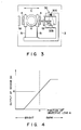
- Fig. 4 represents the operating characteristic of the sensor 30, more precisely the relationship between the output signal of the sensor 30 and the position of the objective lens 6.
- the output signal is at level A when the lens 6 is at its center position.
- the signal is at a higher level as the lens 6 is moved to the left (Fig. 3).
- the optical head 3 is connected to a drive coil 13, which is a movable component of a linear motor 17a.
- This coil 13 is coupled to a linear motor controller 17.
- the position of the linear motor 17a is detected by a sensor 26, which is connected to the controller 17.
- the sensor 26 scans the optical scale 25 mounted on the optical head 3 and outputs an electrical signal representing the position of the linear motor 17a.
- the linear motor 17a has a fixed component. A permanent magnet (not shown) is attached to this fixed component.
- the drive coil 13 When the drive coil 13 is excited under the control of the linear motor controller 17, it moves in the radial direction of the optical disk 1. As a result, the head 3, which is coupled to the drive coil 13, is moved in the radial direction of the disk 1.
- the semiconductor laser 9 When the semiconductor laser 9 is driven under the control of a laser control circuit 14, it emits a laser beam.
- the beam is applied onto the optical disk 1 via the collimator lens 11a, the half-prism 11b, and the objective lens 6.
- the beam reflected from the disk 1 is guided to the half-prism 11c through the objective lens 6 and half-prism 11b.
- the half-prism 11c splits the laser beam into two beams.
- the first beam transmitted from the half-prism 11c is applied to a pair of tracking-position sensors 8 through the focussing lens 10
- the second beam transmitted (reflected) from the half-prism 11c is applied to a pair of focus-position sensors 7 through the focussing lens 11d and the knife-edge 12.
- the output signals of the tracking-position sensors 8 are input to a differential amplifier OP1.
- the amplifier OP1 generates a tracking-error signal ⁇ from the output signals of the sensors 8.
- the tracking-error signal ⁇ which has the waveform illustrated in Fig. 5A, is supplied from the amplifier OP1 to a tracking controller 16 and a binary circuit 40.
- the signal ⁇ is supplied from the tracking controller 16 to linear motor controller 17.
- the tracking controller 16 drives the drive coils 4, thereby moving the objective lens 6 in the tracking direction.
- the tracking controller 16 drives the drive coils 4, whereby the objective lens 6 jumps from one track to another.
- the binary circuit 40 converts the tracking-error signal ⁇ to a binary signal ⁇ which has the waveform shown in Fig. 5B.
- the binary signal ⁇ is supplied to a counter 41.
- the counter 41 counts every binary signal output from the binary circuit 40, and outputs a signal which represents the count value ⁇ as is shown in Fig. 5C. This signal is supplied to the CPU 23.
- the focus-position sensors 7 generate signals indicating the position of the focal point of the laser beam. These signals are input to an differential amplifier OP2.
- the output signal of the differential amplifier OP2 is input to a focussing controller 15.
- the output signal of this controller 15 is supplied to drive coils 5. These coils 5 move the objective lens 6 toward or away from the optical disk 1 in accordance with the signal supplied from the controller 15, thereby correctly focussing the laser beam onto the optical disk 1.
- the tracking-position sensors 8 produce signals from the laser beam reflected from the pits formed in the track of the disk 1. These signals are input to a reproduction circuit 19.
- the circuit 19 processes the signals into image data and address data (e.g., the track number, or the like).
- the laser controller 14, the focussing controller 15, the tracking controller 16, the linear motor controller 17, the motor controller 18, and the reproduction circuit 19 are coupled to the CPU 23 by means of a signal bus 20. Therefore, in a overall sense, they are all controlled by the CPU 23.
- the signal bus 20 is connected to a host computer 27, so that the number of any track accessed, the data read from the accessed track, and the image data reproduced by the reproduction circuit 19 can be supplied to the host computer 27.
- An A/D converter 21 is connected between the focussing controller 15 and the signal bus 20. It converts the output of the controller 15 into digital data. The digital data is input via the bus line 20 to the CPU 23 which is connected to the signal bus 20.
- a D/A converter 22 is coupled to the bus line 20 in order to receive data from, and supply data to, the focussing controller 15, the tracking controller 16, the linear motor controller 17 and the CPU 23.
- the optical disk apparatus further comprises an oscillator (not shown) which generates such sampling pulses as are shown in Fig. 5D.
- the CPU 23 includes an internal counter 23a functioning as a loop counter.
- the internal counter 23a counts the sampling pulses whose number is proportional to the count value ⁇ which the counter 41 has upon completion of the coarse accessing or at the start of the re-tracking. This counting of sampling pulses is performed as is illustrated in Fig. 5E.
- the CPU 23 determines that the frequency of the tracking-error signal ⁇ has decreased, indicating a decrease in the rate of change of relative tracking position between the optical disk 1 and the objective lens 6. Then, the CPU 23 outputs a tracking-on signal to the tracking controller 16 and also to the counter 41.
- the counter 41 is cleared by the tracking-on signal output from the CPU 23.
- the CPU 23 determines that a tracking error has been made, that is, the laser beam has not been focused onto a target track of the optical disk 1.
- the CPU 23 outputs a tracking re-try signal to the tracking controller 16.
- the CPU 23 determines whether or not the count value ⁇ of the counter 41 is greater than a prescribed value. If YES, the CPU 23 determines that a tracking error has been made. In this case, too, the CPU 23 outputs a tracking re-try signal to the tracking controller 16.
- the controller 16 comprises a tracking circuit 16a and a switching circuit 16b.
- the switching circuit 16b has a changeover switch SW1 connected to the output of the differential amplifier OP1, a differential amplifier 60 whose inverting input is coupled to the sensor 30 (i.e., phototransistor 30b), a changeover switch SW2 connected to the output of the differential amplifier 60, and a two-input adder 61 whose inputs are connected to the changeover switches SW1 and SW2, respectively. Both changeover switches SW1 and SW2 are connected to the CPU 23 and controlled by a switching signal supplied therefrom.
- the tracking circuit 16a includes a phase compensator 62 coupled to the output of the adder 61, an amplifier circuit 63 connected to the output of the phase compensator 62, and a driver circuit 64 coupled to the output of the amplifier circuit 63.
- the tracking-error signal ⁇ is supplied from the differential amplifier OP1 to the changeover switch SW1 of the switching circuit 16b.
- the switch SW1 is turned on or off in accordance with the switching signal supplied from the CPU 23. As long as the switch SW1 remains off, the tracking-error signal ⁇ is not supplied to the adder 61. When the switch SW1 is turned on that the signal ⁇ is supplied to the adder 61.
- the electrical signal output by the sensor 30, whose level represents the position of the objective lens 6, is input to the inverting input of the differential amplifier 60.
- a reference signal, whose level represents the reference position of the lens 6, is input to the non-inverting input of the differential amplifier 60.
- the amplifier 60 produces a position signal whose level represents the distance, or difference, between the reference position and actual position of the objective lens 6.
- the position signal is supplied to the changeover switch SW2.
- the switch SW2 is turned on or off in accordance with the switching signal output from the CPU 23. Until the switch SW2 is turned on, the position signal is not supplied to the adder 61. When the switch SW2 is turned on, the voltage is supplied to the adder 61.
- the output signal of the adder is supplied to the phase compensator 62 of the tracking circuit 16a.
- the compensator 62 compensates the phase of either the tracking-error signal ⁇ or the position signal.
- the signal, thus phase-compensated, is supplied to the amplifier circuit 63 and amplified.
- the amplified signal is input to the driver circuit 64.
- the driver circuit 64 controls the drive coils 4, whereby objective lens 6 is moved in the direction of arrow C (Fig. 3), that is, in the radial direction of the optical disk 1.
- the switches SW1 and SW2 are turned on and off, respectively.
- the switches SW1 and SW2 are turned off an on, respectively.
- the tracking-error signal ⁇ is supplied from the CPU 23 to the driver 43 via the switch SW1, the adder 61, the phase compensator 62, and the amplifier circuit 63, whereby the driver 64 drives the drive coils 4, thus achieving a tracking control.
- the position signal is supplied from the differential amplifier 60 to the driver 43 via the switch SW2, the adder 61, the phase compensator 62, and the amplifier circuit 63, whereby the driver 64 drives the drive coils 4, such that the lens 6 is moved to a predetermined position within the optical head 3, i.e., the center position with in the head 3.
- the operation of the optical disk apparatus will now be explained with reference to the flow chart shown in Figs. 6 and 7. Assuming that the host computer 27 gives the number of a target track to the CPU 23 through the bus line 20, the CPU 23 compares the number of the target track with the number of the track which the optical head 3 is accessing actually. If the difference between the track numbers compared is 10 or more, the CPU 23 determines that the optical head 3 is performing coarse track-accessing.
- the CPU 23 determines that the optical head 3 is performing coarse track-accessing, it supplied to the linear motor controller 17 via the D/A converter 22 the data representing the scale value which corresponds to the number of the target track.
- the controller 17 applies an excitation current to the driver coil 13 of the linear motor 17a, which corresponds to the scale value, thereby moving the linear motor 17a.
- the motor 17a is mode in the radial direction of the optical disk 1
- the optical head 3 is moved to the position defined by the scale value.
- the head 3 coarsely accesses the target track of the optical disk 1.
- the CPU 23 turns off the changeover switch SW1 of the tracking controller 16, whereby the tracking is interrupted. Simultaneously, the CPU 23 turns on the changeover switch SW2 of the tracking controller 16. Then, the differential amplifier 60 supplies the position signal (i.e., the voltage proportional to the level difference between the output signal of the sensor 30 and the reference signal) to the driver circuit 64 through the switch SW2, the adder 61, the phase compensator 62, and the amplifier circuit 63.
- the driver circuit 64 drives the coils 4 in accordance with the position signal, and the coils 4 move the objective lens 6 to, and holds the lens 6 at, the center position with the optical head 3.
- the differential amplifier OP1 When the lens 6 is stopped at the center position within the optical head 3, that is, when the coarse track-accessing is completed, a reaction is applied to the objective lens 6.
- the lens 6 vibrates since it is supported by the wire suspensions 51.
- the spot, which the laser beams forms on the optical disk 1 moves across a track of the disk 1.
- the differential amplifier OP1 generates a tracking-error signal ⁇ (Fig. 5A) from the output signals of the tracking-position sensors 8 incorporated in the optical head 3.
- the signal ⁇ is supplied to the binary circuit 40.
- the circuit 40 converts the signal ⁇ to a binary signal ⁇ (Fig. 5B).
- the binary signal ⁇ is supplied to a counter 41.
- the counter 41 counts every binary signal output from the binary circuit 40, and outputs a signal which represents the count value ⁇ (Fig. 5C).
- the count value ⁇ is input to the CPU 13.
- the CPU 23 determines the frequency of the tracking-error signal ⁇ . Further, it determines the relative rate of change of tracking position (referred to as "speed" in Fig. 6) between the optical disk 1 and the objective lens 6 from the frequency of the tracking-error signal ⁇ . When this relative rate of change of tracking position decreases below a predetermined value, that is, when it becomes necessary to apply servo, or fine, tracking to the optical head 2, the CPU 23 causes the tracking controller 16 to start performing servo tracking, in step ST10 (Fig. 6). More precisely, as is illustrated in Fig. 5E, the internal counter 23a counts the sampling pulses whose number is proportional to the count value ⁇ which the counter 41 has upon completion of the coarse accessing.
- the CPU 23 determines that the frequency of the tracking-error signal ⁇ has decreased, indicating a decrease in the relative rate of change of tracking position between the optical disk 1 and the objective lens 6. Then, the CPU 23 outputs a tracking-on signal to the tracking controller 16 and also to the counter 41.
- step ST1 the optical head 3 is stopped in step ST1.
- step ST2 the CPU 23 clears the internal counter 23a in step ST2.
- step ST3 the CPU 23 reads the count value ⁇ of the counter 41, which is "1" at this time.
- a predetermined time is made to lapse in step ST4.
- step ST5 upon lapse of this time, when the oscillator (not shown) outputs a sampling pulse, the CPU 23 reads the count value ⁇ which the counter 41 has at this time.
- step ST6 the CPU 23 determines whether or not the value ⁇ is equal to the count value ⁇ which has been read in step ST3. If YES, the count of the internal counter 23a is incremented by one, in step ST7.
- step ST8 the CPU 23 determines whether or no the count value of the counter 23a is greater than the predetermine value, i.e., "6.” If NO, the operation returns to step ST4.
- the operation loop a consisting of steps ST4 to ST8 is repeated until the count value of the internal counter 23a increases to "6.”
- the CPU 23 determines that the frequency of the tracking-error signal ⁇ has decreased and that the relative rate-of-change of tracking position the optical disk 1 and the objective lens 6 has become low.
- step ST9 the CPU 23 outputs a tracking-on signal to the tracking controller 16 and also to the counter 41.
- step ST5 If No in step ST5, that is, if the count value ⁇ of the counter 41 has changed before it reaches the predetermined value of "6,” the operation returns to step ST2, in which the internal counter 23a is cleared.
- the operation loop b consisting of step ST2 to ST6 is repeated until the CPU 23 determines, in step ST6, that the value ⁇ read in step ST5 is equal to the value ⁇ read in step ST3.
- the laser beam can be applied onto the target track, thus achieving a tracking-on, whenever the frequency of the signal ⁇ decreases, indicating that the relative rate of change of tracking position between the optical disk 1 and the objective lens 6 has become low. Even if the amplitude of the signal ⁇ changes very much immediately after the optical head 3 has been stopped, it suffices to clear the internal counter 23a. Also as can be understood from the above, the higher the frequency of the sampling pulse signal than that of the signal ⁇ , the less time is required to achieve the tracking-on.
- the tracking-on can be accomplished more quickly than in the conventional optical disk apparatus wherein the laser emits a beam with a time lag after the optical head has been stopped.
- the optical disk apparatus of this invention can access the target track at a higher speed.
- the tracking-on signal supplied from the CPU 23 turns on the changeover which SW1 of the tracking controller 16, and turns off the changeover switch SW2 of the controller 16.
- the tracking-error signal ⁇ output by the differential amplifier OP1 is input to the driver circuit 64 through the changeover switch SW1, the adder 61, and the phase compensator 62.
- the driver circuit 64 drives the drive coils 4, controlling the drive coils 4, such that the objective lens 6 is moved in the direction of arrow C (Fig. 3), thus carrying out servo, or fine, tracking as is illustrated in Fig. 5F.
- the laser beam has been applied onto the target track of the optical disk 1, it traces the target track as the disk 1 is rotated.
- the laser beam is applied onto the target track when the relative rate-of-change of tracking position between the optical disk 1 and the objective lens 6 decreases after the coarse accessing has been completed. Then, as is shown in Fig. 6, the CPU 23 clears the counter 41 in step ST11. A predetermined time (e.g., a few milliseconds) is made to lapse in step ST12. In the next step, ST13, the CPU 23 determines whether or not the counter value ⁇ of the counter 41 exceeds "3" or less. If NO, the operation goes to step ST14, in which the counter 41 is cleared, and no further control of the optical head 3 is performed.
- step ST14 in which the counter 41 is cleared, and no further control of the optical head 3 is performed.
- step ST13 If it is determined, in step ST13, that the count value ⁇ of the counter 41 is "3" or more, the CPU 23 determines a tracking error, and outputs a tracking re-try signal to the tracking controller 16. As a result of this, the changeover switch SW1 of the controller 16 is turned off, thus terminating the tracking operation. Simultaneously, the changeover switch SW2 of the controller 16 is turned on, whereby a position signal, i.e., the voltage corresponding to the difference between the reference position signal and the output signal of the sensor 30, is supplied from the differential amplifier 60 to the driver circuit 64 via the switch SW2, the adder 61, the phase compensator 62, and the amplifier circuit 63. The driver circuit 64 drives the drive coils 4 in accordance with the position signal, thereby moving the objective lens 6 to the center position within the optical head 3.
- a position signal i.e., the voltage corresponding to the difference between the reference position signal and the output signal of the sensor 30
- the CPU 23 executes steps ST1 to ST9. That is, the CPU 23 causes the tracking controller 16 to start the servo tracking when the relative rate-of-change of tracking position between the disk 1 and the lens 6, which is determined from the frequency of the tracking-error signal ⁇ , decreases below the predetermined value (i.e., the relative rate-of-change of tracking position so low as requires the tracking servo) (steps ST15 to ST20).
- the operation returns to step ST11.
- the linear motor 13 keeps moving the head 3 in the radial direction of the optical disk 1, so that the laser beam traces the tracks.
- the CPU 23 determines again, from the count value ⁇ of the counter 41, whether or not the beam is applied to the target track (steps ST11 to ST14).
- the vibration of the objective lens 6 is suppressed. Therefore, the relative rate-of-change of tracking position between the disk 1 and the lens 6 is reduced even when the lens 6 is vibrating upon accessing the target track. This makes it easy to apply the laser beam to the target track.
- the tracking-on is started when the relative rate-of-change of tracking position between the disk 1 and the lens 6 becomes so low that the servo tracking is no longer required. Since the tracking is performed in accordance with the relative rate-of-change of tracking position between the disk 1 and the lens 6, the chance of successful tracking is great. Even if the tracking turns out to be unsuccessful, the tracking re-try operation is immediately achieved, to apply the laser beam to the target track.
- the CPU 23 determines whether or not the count value ⁇ of the counter 41 is greater than a prescribed value. If YES, the CPU 23 determines that a tracking error has been made, and outputs a tracking re-try signal to the tracking controller 16 in step ST13. Thereafter, steps ST15 to ST20 are preformed.
- the CPU 23 determines whether or not the tracking is successful upon the completion of the coarse accessing and during the data-reproducing operation. If NO due to the vibration of the head 3 caused by an external force upon the completion of the coarse accessing or during the data reproduction, the CPU 23 immediately outputs a tracking re-try signal to the tracking controller 16, thereby resuming the successful tracking. This helps to reduce the chance of tracking errors, and ultimately enhance the reliability of the optical disk apparatus.
- the optical head 3 can apply the laser beam onto the target track. Therefore, the vibration of the objective lens 6 can be suppressed within a short time after the completion of the coarse accessing, whereupon the tracking by means of the lens 6 is started. As a result, the optical head 3 can access the target track at high speed.
Abstract
Description
- The present invention relates to an optical disk apparatus and, more particularly to an optical disk apparatus wherein data can be optically recorded on, and reproduced from, the tracks of a memory disk while the disk and an optical head are moving relative to each other.
- Optical disk apparatuses have been in practical use, each typically having an optical head comprising a semiconductor laser and an objective lens. The laser emits a beam, and the objective lens focuses the laser beam onto a track of an optical disk which is spinning and located near the optical head, thereby to record data on the track or to reproduce data therefrom. The optical head undergoes focus control so that the objective lens focuses the laser beam appropriately. Also, the head undergoes tracking control so that the laser beam focused by the objective lens is applied onto a desired track.
- The optical disk apparatus further has a linear motor and an objective drive mechanism, as is disclosed in U.S. Patent No. 4,037,252. The linear motor moves the optical head in the radial direction of the optical disk, when the apparatus is set in a coarse access mode. The objective drive mechanism also moves the objective lens toward or away from the optical disk, when the apparatus is set in the fine access mode.
- To access any target track of the optical disk, the apparatus is first set in coarse access mode. In the coarse access mode, the linear motor moves the optical head toward the target track. The head applies a laser beam to the optical disk. The beam is reflected from one of the tracks, and the position of this track is determined from the reflected laser beam. If the position thus determined greatly differs from the position of the target track, the apparatus is continuously set in the coarse access mode. Hence, the linear motor is driven again, moving the head toward the target track. If the position differs a little from that of the target track, the access mode is changed to the fine access mode. In this case, the objective drive mechanism moves the objective lens to focus the laser beam, thus achieving a fine access to the target track.
- The optical disk apparatus further comprises a position detector. While the apparatus is set in the coarse access mode, this detector reads, or scans, the optical scale mounted on the optical head, thereby determining the position of the head and, thus, the distance the head has been moved.
- The optical disk apparatus, described above, have two drawbacks. First, once the optical head is vibrated due to an external force and fails to track a target track after it has been moved by the linear motor or during the optical reproduction of the recorded data, it can no longer track any track. Second, the optical head can hardly accomplish a stable tracking, for the reason discussed in the following paragraph.
- Since the objective lens is suspended from a fixed member by a wire suspension, it is vibrated in the radial direction of the optical disk when the head is stopped, due to the deceleration of the linear motor. If the laser emits a beam onto the disk while the objective lens is vibrating, the position of the track to which the head has been moved cannot be detected correctly. Hence, the laser is not turned on, or the objective drive mechanism does not move the objective lens, until a period of time (about 20 msec), which is slightly longer than the time the lens requires to stops vibrating, elapses after the optical head has been stopped. In other words, the tracking of the disk is started upon lapse of a predetermined time after the head has been stopped, regardless of the relative speed between the head and the disk. When this relative speed is higher than the normal value because the disk is eccentrically located with respect to the spindle of the disk apparatus, or because the lens is vibrating when the linear motor is stopped, a tracking error signal generated from the laser beam reflected from the disk will have a frequency exceeding a predetermined tracking-servo range. Consequently, the optical head cannot achieve a stable tracking.
- It is an object of the present invention to provide an optical disk apparatus which is reliable in that the optical head can track any track of an optical disk even after it has failed to track a target track due to an external force applied to it upon stopping at a target track or while optically reproducing data from the disk.
- Another object of the invention is to provide an optical disk apparatus in which the optical head can achieve a stable tracking upon stopping at a target track of an optical disk, thus accessing the target track with high accuracy within a short period of time.
- According to the present invention, there is provided an optical disk apparatus comprising:
an optical head having focusing means for focusing a light beam onto an optical recording medium having tracks, and detecting means for detecting the light beam reflected from the optical recording medium;
drive means for moving the focusing means in a direction perpendicular to the axis of the light beam;
signal-generating means for generating a tracking-error signal in response to a detection signal output from the detecting means;
tracking means for causing the drive means to move the focusing means to a target track of the optical recording medium, in response to the tracking-error signal generated by the signal-generating means;
first judging means for determining a tracking error from the tracking-error signal generated by the signal-generating means;
positioning means for causing the drive means to move the focusing means to a predetermined position within the optical head when the first judging means determines a tracking error;
second judging means for determining a relative rate-of-change of tracking position between the focusing means and the optical recording means from the frequency of the tracking-error signal when the focusing means is moved to the predetermined position within the optical head; and
control means for controlling the tracking means such that the tracking means causes the drive means to stop moving the focusing means when first judging means determines a tracking error, and to start moving the focusing means when the second judging means determines a decrease of the relative rate-of-change of tracking position between the optical recording medium and the focusing means which has been moved to the predetermined position within the optical head. - Further, according to the invention, there is provided an optical disk apparatus comprising:
an optical head having focusing means for focusing a light beam onto an optical recording medium having tracks, and detecting means for detecting the light beam reflected from the optical recording medium;
first drive means for moving the optical head in the radial direction of the optical recording medium;
second drive means for moving the focussing means in a direction perpendicular to the axis of the light beam;
first signal-generating means for generating a tracking-error signal in response to a detection signal output from the detecting means;
tracking means for causing the second drive means to move the focussing means to a target track of the optical recording medium, in response to the tracking-error signal generated by first the signal-generating means;
second signal-generating means for generating a signal for operating the second drive means, there by to move the focussing means to the target track;
positioning means for causing the second drive means to move the focussing means to a predetermined position within the optical head when the focussing means is moved to the target track;
judging means for determining a relative rate-of-change of tracking position between the focussing means and the optical recording means from the frequency of the tracking-error signal when the focussing means is moved to the predetermined position within the optical head; and
control means for controlling the tracking means such that the tracking means causes the second drive means to stop moving the focussing means when first drive means starts moving the optical head toward the target track, and to start moving the focussing means when the optical head is moved to the target track, and the judging means determines a decrease of the relative rate-of-change of tracking position between the optical recording medium and the focussing means which has been moved to the predetermined position within the optical head. - This invention can be more fully understood from the following detailed description when taken in conjunction with the accompanying drawings, in which:
- Fig. 1 is a block diagram illustrating an optical disk apparatus according to the present invention;
- Fig. 2 is diagram showing the means incorporated in the apparatus, for suppressing the vibration of an objective lens;
- Fig. 3 is a plan view showing the optical head used in the apparatus shown in Fig. 1;
- Fig. 4 is a graph representing the relationship between the position of the objective lens and the output of the sensor incorporated in the optical head;
- Fig. 5A illustrates the waveform of a tracking-error signal;
- Fig. 5B shows a binary signal output by the binary circuit incorporated in the apparatus;
- Fig. 5C shows how the count value of the counter used in the apparatus changes;
- Fig. 5D is a diagram showing the sampling pulse signal generated by the oscillator incorporated in the apparatus;
- Fig. 5E is a view for explaining the number of sampling pulses counted by an internal counter which corresponds to that counted by a counter;
- Fig. 5F illustrates the waveform of a tracking-error signal different from the signal shown in Fig. 5A; and
- Figs. 6 and 7 form a flow chart explaining the operation of the optical disk apparatus shown in Fig. 1.
- Fig. 1 schematically illustrates an optical disk apparatus, which is an embodiment of the present invention. As is shown in Fig. 1, an
optical disk 1 is connected to amotor 2. Thedisk 1 is rotated at a constant speed when themotor 2 is driven under the control of amotor control circuit 18. - The
optical disk 1 comprises a substrate made of glass or plastics and a doughnut-shaped recording layer made of metal such as tellurium or bismuth and coated on the substrate. Thedisk 1 has a spiral track or concentric tracks on the lower surface. - An
optical head 3 is located below theoptical disk 1 and opposes the lower surface thereof. As is disclosed in U.S. Patent No. 4,684,797, and as is illustrated in Figs. 1 and 2, theoptical head 3 comprises drive coils 4 and 5, anobjective lens 6, a focus-position sensor 7, a tracking-position sensor 8, asemiconductor laser 9, a focussinglens 10, acollimator lens 11a, half-prisms 11b and 11c, another focussing lens 11d, a knife-edge 12, and a light-receiving element PD. The drive coils 4 and 5 are used to move theobjective lens 6. Thecollimator lens 11a is designed to collimate the laser beam emitted from thesemiconductor laser 9. The element PD is used to detect the intensity of the beam emitted from thelaser 9. For the details of the optical system incorporated in theoptical head 3, refer to U.S. Patent No. 4,684,797. - As is illustrated in Fig. 3, the
objective lens 6 is suspended from a fixed member (not shown) by means of twowire suspensions 51. Thelens 6 can be moved along its optical axis by means of the drive coils 5 to focus the laser beam to various degrees. It can also be moved orthogonal to the focussing direction, that is, in a direction which is perpendicular to its optical axis by means of the drive coils 4. -
Permanent magnets 52 are attached to fixed members. Thesemagnets 52 cooperate with the drive coils 4 to move theobjective lens 6 in the direction of an arrow c (Fig. 3), that is, in the direction perpendicular to the optical axis of thelens 6. - A
shield 6a is located close to thelens 6, and can be moved together with the lens. Asensor 30 is attached to the frame of theoptical head 3, and opposes theshield 6a, in the sense that it does not move withlens 6. Thissensor 30 comprises a photo-interrupter which includes an LED (Light-Emitting Diode) 30a and aphototransistor 30b functioning as a light-receiving element. - When the
objective lens 6 is at its center position, theshield 6a assumes such a position as to shield half the light emitted from theLED 30a, and thephototransistor 30b generates an electrical signal at an intermediate level. The more thelens 6 and theshield 6a move to the left, the more light thephototransistor 30b receives to generate an electrical signal at a higher level. The more thelens 6 and theshield 6a move to the right, the less light thephototransistor 30b receives to generates an electrical signal at a lower level. Thus, the signal output by thesensor 30 represents the position of the objective lens along a axis parallel to the direction of arrow C. - Fig. 4 represents the operating characteristic of the
sensor 30, more precisely the relationship between the output signal of thesensor 30 and the position of theobjective lens 6. As is evident from Fig. 4, the output signal is at level A when thelens 6 is at its center position. As can be understood also from Fig. 4, the signal is at a higher level as thelens 6 is moved to the left (Fig. 3). - As is shown in Fig. 1, the
optical head 3 is connected to adrive coil 13, which is a movable component of alinear motor 17a. Thiscoil 13 is coupled to alinear motor controller 17. The position of thelinear motor 17a is detected by asensor 26, which is connected to thecontroller 17. Thesensor 26 scans theoptical scale 25 mounted on theoptical head 3 and outputs an electrical signal representing the position of thelinear motor 17a. - The
linear motor 17a has a fixed component. A permanent magnet (not shown) is attached to this fixed component. When thedrive coil 13 is excited under the control of thelinear motor controller 17, it moves in the radial direction of theoptical disk 1. As a result, thehead 3, which is coupled to thedrive coil 13, is moved in the radial direction of thedisk 1. - When the
semiconductor laser 9 is driven under the control of alaser control circuit 14, it emits a laser beam. The beam is applied onto theoptical disk 1 via thecollimator lens 11a, the half-prism 11b, and theobjective lens 6. The beam reflected from thedisk 1 is guided to the half-prism 11c through theobjective lens 6 and half-prism 11b. The half-prism 11c splits the laser beam into two beams. The first beam transmitted from the half-prism 11c is applied to a pair of tracking-position sensors 8 through the focussinglens 10, whereas the second beam transmitted (reflected) from the half-prism 11c is applied to a pair of focus-position sensors 7 through the focussing lens 11d and the knife-edge 12. - The output signals of the tracking-
position sensors 8 are input to a differential amplifier OP1. The amplifier OP1 generates a tracking-error signal α from the output signals of thesensors 8. The tracking-error signal α, which has the waveform illustrated in Fig. 5A, is supplied from the amplifier OP1 to a trackingcontroller 16 and abinary circuit 40. The signal α is supplied from the trackingcontroller 16 tolinear motor controller 17. In response to the tracking-error signal or the output signal of thesensor 30, the trackingcontroller 16 drives the drive coils 4, thereby moving theobjective lens 6 in the tracking direction. Further, in response to a track-jump signal supplied from a CPU 23 (later described), the trackingcontroller 16 drives the drive coils 4, whereby theobjective lens 6 jumps from one track to another. - The
binary circuit 40 converts the tracking-error signal α to a binary signal β which has the waveform shown in Fig. 5B. The binary signal β is supplied to acounter 41. The counter 41 counts every binary signal output from thebinary circuit 40, and outputs a signal which represents the count value γ as is shown in Fig. 5C. This signal is supplied to theCPU 23. - The focus-
position sensors 7 generate signals indicating the position of the focal point of the laser beam. These signals are input to an differential amplifier OP2. The output signal of the differential amplifier OP2 is input to a focussingcontroller 15. The output signal of thiscontroller 15 is supplied to drivecoils 5. Thesecoils 5 move theobjective lens 6 toward or away from theoptical disk 1 in accordance with the signal supplied from thecontroller 15, thereby correctly focussing the laser beam onto theoptical disk 1. - While the focussing control and the tracking control are being performed as described above, the tracking-
position sensors 8 produce signals from the laser beam reflected from the pits formed in the track of thedisk 1. These signals are input to areproduction circuit 19. Thecircuit 19 processes the signals into image data and address data (e.g., the track number, or the like). - The
laser controller 14, the focussingcontroller 15, the trackingcontroller 16, thelinear motor controller 17, themotor controller 18, and thereproduction circuit 19 are coupled to theCPU 23 by means of asignal bus 20. Therefore, in a overall sense, they are all controlled by theCPU 23. Thesignal bus 20 is connected to ahost computer 27, so that the number of any track accessed, the data read from the accessed track, and the image data reproduced by thereproduction circuit 19 can be supplied to thehost computer 27. - An A/
D converter 21 is connected between the focussingcontroller 15 and thesignal bus 20. It converts the output of thecontroller 15 into digital data. The digital data is input via thebus line 20 to theCPU 23 which is connected to thesignal bus 20. A D/A converter 22 is coupled to thebus line 20 in order to receive data from, and supply data to, the focussingcontroller 15, the trackingcontroller 16, thelinear motor controller 17 and theCPU 23. - The optical disk apparatus further comprises an oscillator (not shown) which generates such sampling pulses as are shown in Fig. 5D. The
CPU 23 includes an internal counter 23a functioning as a loop counter. The internal counter 23a counts the sampling pulses whose number is proportional to the count value γ which thecounter 41 has upon completion of the coarse accessing or at the start of the re-tracking. This counting of sampling pulses is performed as is illustrated in Fig. 5E. When the count value of the internal counter 23a is 6 or more, theCPU 23 determines that the frequency of the tracking-error signal α has decreased, indicating a decrease in the rate of change of relative tracking position between theoptical disk 1 and theobjective lens 6. Then, theCPU 23 outputs a tracking-on signal to the trackingcontroller 16 and also to thecounter 41. - The
counter 41 is cleared by the tracking-on signal output from theCPU 23. When the count value γ of thecounter 41 is greater than a prescribed value upon lapse of a predetermined time thereafter, theCPU 23 determines that a tracking error has been made, that is, the laser beam has not been focused onto a target track of theoptical disk 1. The, theCPU 23 outputs a tracking re-try signal to the trackingcontroller 16. - The moment the
disk 1 is rotated 360° for the first time after thecounter 41 has been cleared during the data-reproducing operation, theCPU 23 determines whether or not the count value γ of thecounter 41 is greater than a prescribed value. If YES, theCPU 23 determines that a tracking error has been made. In this case, too, theCPU 23 outputs a tracking re-try signal to the trackingcontroller 16. - The tracking
controller 16 will now be described in detail, with reference to Fig. 2. As is illustrated in this figure, thecontroller 16 comprises a tracking circuit 16a and aswitching circuit 16b. Theswitching circuit 16b has a changeover switch SW1 connected to the output of the differential amplifier OP1, adifferential amplifier 60 whose inverting input is coupled to the sensor 30 (i.e.,phototransistor 30b), a changeover switch SW2 connected to the output of thedifferential amplifier 60, and a two-input adder 61 whose inputs are connected to the changeover switches SW1 and SW2, respectively. Both changeover switches SW1 and SW2 are connected to theCPU 23 and controlled by a switching signal supplied therefrom. The tracking circuit 16a includes aphase compensator 62 coupled to the output of theadder 61, anamplifier circuit 63 connected to the output of thephase compensator 62, and adriver circuit 64 coupled to the output of theamplifier circuit 63. - In operation, the tracking-error signal α is supplied from the differential amplifier OP1 to the changeover switch SW1 of the
switching circuit 16b. The switch SW1 is turned on or off in accordance with the switching signal supplied from theCPU 23. As long as the switch SW1 remains off, the tracking-error signal α is not supplied to theadder 61. When the switch SW1 is turned on that the signal α is supplied to theadder 61. - The electrical signal output by the
sensor 30, whose level represents the position of theobjective lens 6, is input to the inverting input of thedifferential amplifier 60. A reference signal, whose level represents the reference position of thelens 6, is input to the non-inverting input of thedifferential amplifier 60. Hence, theamplifier 60 produces a position signal whose level represents the distance, or difference, between the reference position and actual position of theobjective lens 6. The position signal is supplied to the changeover switch SW2. The switch SW2 is turned on or off in accordance with the switching signal output from theCPU 23. Until the switch SW2 is turned on, the position signal is not supplied to theadder 61. When the switch SW2 is turned on, the voltage is supplied to theadder 61. - The output signal of the adder is supplied to the
phase compensator 62 of the tracking circuit 16a. Thecompensator 62 compensates the phase of either the tracking-error signal α or the position signal. The signal, thus phase-compensated, is supplied to theamplifier circuit 63 and amplified. The amplified signal is input to thedriver circuit 64. In accordance with the input signal, thedriver circuit 64 controls the drive coils 4, wherebyobjective lens 6 is moved in the direction of arrow C (Fig. 3), that is, in the radial direction of theoptical disk 1. - When the
CPU 23 inputs the tracking-on signal to the trackingcontroller 16, the switches SW1 and SW2 are turned on and off, respectively. In contrast, when theCPU 23 supplies the tracking re-try signal to thecontroller 16, the switches SW1 and SW2 are turned off an on, respectively. In the former case, the tracking-error signal α is supplied from theCPU 23 to the driver 43 via the switch SW1, theadder 61, thephase compensator 62, and theamplifier circuit 63, whereby thedriver 64 drives the drive coils 4, thus achieving a tracking control. In the latter case, the position signal is supplied from thedifferential amplifier 60 to the driver 43 via the switch SW2, theadder 61, thephase compensator 62, and theamplifier circuit 63, whereby thedriver 64 drives the drive coils 4, such that thelens 6 is moved to a predetermined position within theoptical head 3, i.e., the center position with in thehead 3. - The operation of the optical disk apparatus, described above, will now be explained with reference to the flow chart shown in Figs. 6 and 7. Assuming that the
host computer 27 gives the number of a target track to theCPU 23 through thebus line 20, theCPU 23 compares the number of the target track with the number of the track which theoptical head 3 is accessing actually. If the difference between the track numbers compared is 10 or more, theCPU 23 determines that theoptical head 3 is performing coarse track-accessing. - When the
CPU 23 determines that theoptical head 3 is performing coarse track-accessing, it supplied to thelinear motor controller 17 via the D/A converter 22 the data representing the scale value which corresponds to the number of the target track. Thecontroller 17 applies an excitation current to thedriver coil 13 of thelinear motor 17a, which corresponds to the scale value, thereby moving thelinear motor 17a. As themotor 17a is mode in the radial direction of theoptical disk 1, theoptical head 3 is moved to the position defined by the scale value. As a result, thehead 3 coarsely accesses the target track of theoptical disk 1. - When the
optical head 3 starts moving, theCPU 23 turns off the changeover switch SW1 of the trackingcontroller 16, whereby the tracking is interrupted. Simultaneously, theCPU 23 turns on the changeover switch SW2 of the trackingcontroller 16. Then, thedifferential amplifier 60 supplies the position signal (i.e., the voltage proportional to the level difference between the output signal of thesensor 30 and the reference signal) to thedriver circuit 64 through the switch SW2, theadder 61, thephase compensator 62, and theamplifier circuit 63. Thedriver circuit 64 drives thecoils 4 in accordance with the position signal, and thecoils 4 move theobjective lens 6 to, and holds thelens 6 at, the center position with theoptical head 3. - When the
lens 6 is stopped at the center position within theoptical head 3, that is, when the coarse track-accessing is completed, a reaction is applied to theobjective lens 6. Thelens 6 vibrates since it is supported by thewire suspensions 51. As a result, the spot, which the laser beams forms on theoptical disk 1, moves across a track of thedisk 1. In this case, the differential amplifier OP1 generates a tracking-error signal α (Fig. 5A) from the output signals of the tracking-position sensors 8 incorporated in theoptical head 3. The signal α is supplied to thebinary circuit 40. Thecircuit 40 converts the signal α to a binary signal β (Fig. 5B). The binary signal β is supplied to acounter 41. The counter 41 counts every binary signal output from thebinary circuit 40, and outputs a signal which represents the count value γ (Fig. 5C). The count value γ is input to theCPU 13. - From the count value γ, the
CPU 23 determines the frequency of the tracking-error signal α. Further, it determines the relative rate of change of tracking position (referred to as "speed" in Fig. 6) between theoptical disk 1 and theobjective lens 6 from the frequency of the tracking-error signal α. When this relative rate of change of tracking position decreases below a predetermined value, that is, when it becomes necessary to apply servo, or fine, tracking to theoptical head 2, theCPU 23 causes the trackingcontroller 16 to start performing servo tracking, in step ST10 (Fig. 6). More precisely, as is illustrated in Fig. 5E, the internal counter 23a counts the sampling pulses whose number is proportional to the count value γ which thecounter 41 has upon completion of the coarse accessing. When the count value of the counter 23a is 6 or more, theCPU 23 determines that the frequency of the tracking-error signal α has decreased, indicating a decrease in the relative rate of change of tracking position between theoptical disk 1 and theobjective lens 6. Then, theCPU 23 outputs a tracking-on signal to the trackingcontroller 16 and also to thecounter 41. - The servo tracking will be explained in detail, with reference to Fig. 7.
- First, the
optical head 3 is stopped in step ST1. Next, theCPU 23 clears the internal counter 23a in step ST2. Then, in step ST3, theCPU 23 reads the count value γ of thecounter 41, which is "1" at this time. Then, a predetermined time is made to lapse in step ST4. In the next step, ST5, upon lapse of this time, when the oscillator (not shown) outputs a sampling pulse, theCPU 23 reads the count value γ which thecounter 41 has at this time. In step ST6, theCPU 23 determines whether or not the value γ is equal to the count value γ which has been read in step ST3. If YES, the count of the internal counter 23a is incremented by one, in step ST7. Then, in step ST8, theCPU 23 determines whether or no the count value of the counter 23a is greater than the predetermine value, i.e., "6." If NO, the operation returns to step ST4. The operation loop a consisting of steps ST4 to ST8 is repeated until the count value of the internal counter 23a increases to "6." When the count value of the counter 23a has reached the predetermined value of "6," theCPU 23 determines that the frequency of the tracking-error signal α has decreased and that the relative rate-of-change of tracking position theoptical disk 1 and theobjective lens 6 has become low. In step ST9, theCPU 23 outputs a tracking-on signal to the trackingcontroller 16 and also to thecounter 41. - If No in step ST5, that is, if the count value γ of the
counter 41 has changed before it reaches the predetermined value of "6," the operation returns to step ST2, in which the internal counter 23a is cleared. The operation loop b consisting of step ST2 to ST6 is repeated until theCPU 23 determines, in step ST6, that the value γ read in step ST5 is equal to the value γ read in step ST3. - When the count value of the internal counter 23a is "1," the loop operation a is repeated three times before the next operation loop is performed. When the count value of the internal counter 23a is "2," the loop operation a is repeated two times before the next operation loop is performed. And, when the count value of the internal counter 23a is "6," the loop operation a is repeated six times before the next operation loop is performed. In each of these cases, the count value γ of the
counter 41 remains unchanged, and the operation goes out of the loop operation a, whereby theCPU 23 yields as output a tracking-on signal in step ST9. - As can be understood from the above, the laser beam can be applied onto the target track, thus achieving a tracking-on, whenever the frequency of the signal α decreases, indicating that the relative rate of change of tracking position between the
optical disk 1 and theobjective lens 6 has become low. Even if the amplitude of the signal α changes very much immediately after theoptical head 3 has been stopped, it suffices to clear the internal counter 23a. Also as can be understood from the above, the higher the frequency of the sampling pulse signal than that of the signal α, the less time is required to achieve the tracking-on. For example, when the sampling pulses are generated at the frequency of 2 KHz (one pulse every 500 µsec), whereas the frequency of the signal α is 1 KHz, the tracking-on can be accomplished more quickly than in the conventional optical disk apparatus wherein the laser emits a beam with a time lag after the optical head has been stopped. Obviously, the optical disk apparatus of this invention can access the target track at a higher speed. - The tracking-on signal supplied from the
CPU 23 turns on the changeover which SW1 of the trackingcontroller 16, and turns off the changeover switch SW2 of thecontroller 16. As a result, the tracking-error signal α output by the differential amplifier OP1 is input to thedriver circuit 64 through the changeover switch SW1, theadder 61, and thephase compensator 62. In response to the tracking-error signal α, thedriver circuit 64 drives the drive coils 4, controlling the drive coils 4, such that theobjective lens 6 is moved in the direction of arrow C (Fig. 3), thus carrying out servo, or fine, tracking as is illustrated in Fig. 5F. Now that, the laser beam has been applied onto the target track of theoptical disk 1, it traces the target track as thedisk 1 is rotated. - As has been described, the laser beam is applied onto the target track when the relative rate-of-change of tracking position between the
optical disk 1 and theobjective lens 6 decreases after the coarse accessing has been completed. Then, as is shown in Fig. 6, theCPU 23 clears thecounter 41 in step ST11. A predetermined time (e.g., a few milliseconds) is made to lapse in step ST12. In the next step, ST13, theCPU 23 determines whether or not the counter value γ of thecounter 41 exceeds "3" or less. If NO, the operation goes to step ST14, in which thecounter 41 is cleared, and no further control of theoptical head 3 is performed. - When the coarse accessing is completed, there
production circuit 19 reads the number of the track accessed, from the laser beam reflected from the track, and supplied to data representing the track number to theCPU 23. TheCPU 23 compares this track number with the number of the target track. When the difference between the track numbers is ten or more, theCPU 23 drives thelinear motor controller 17, whereby the coarse accessing is performed again. On the other hand, when the difference between the track numbers is less than ten, theCPU 23 drives the trackingcontroller 16, whereby the fine accessing (servo tracking) is performed. To be more precise, the trackingcontroller 16 outputs a track-jump signal to the drive coils 4, thereby moving theobjective lens 6 in the radial direction of theoptical disk 1. As a result of this, the laser beam is applied to the target track. Thus, data can be recorded on, or reproduced from, the target track of theoptical disk 1. - If it is determined, in step ST13, that the count value γ of the
counter 41 is "3" or more, theCPU 23 determines a tracking error, and outputs a tracking re-try signal to the trackingcontroller 16. As a result of this, the changeover switch SW1 of thecontroller 16 is turned off, thus terminating the tracking operation. Simultaneously, the changeover switch SW2 of thecontroller 16 is turned on, whereby a position signal, i.e., the voltage corresponding to the difference between the reference position signal and the output signal of thesensor 30, is supplied from thedifferential amplifier 60 to thedriver circuit 64 via the switch SW2, theadder 61, thephase compensator 62, and theamplifier circuit 63. Thedriver circuit 64 drives the drive coils 4 in accordance with the position signal, thereby moving theobjective lens 6 to the center position within theoptical head 3. - To move the
lens 6 to the center position within theoptical head 3, theCPU 23 executes steps ST1 to ST9. That is, theCPU 23 causes the trackingcontroller 16 to start the servo tracking when the relative rate-of-change of tracking position between thedisk 1 and thelens 6, which is determined from the frequency of the tracking-error signal α, decreases below the predetermined value (i.e., the relative rate-of-change of tracking position so low as requires the tracking servo) (steps ST15 to ST20). When the laser beam is applied to the target track, the operation returns to step ST11. During the servo tracking, thelinear motor 13 keeps moving thehead 3 in the radial direction of theoptical disk 1, so that the laser beam traces the tracks. Hence, theCPU 23 determines again, from the count value γ of thecounter 41, whether or not the beam is applied to the target track (steps ST11 to ST14). - Due to the servo tracking carried out in accordance with the position signal supplied the
sensor 30 during the tracking re-try operation, the vibration of theobjective lens 6 is suppressed. Therefore, the relative rate-of-change of tracking position between thedisk 1 and thelens 6 is reduced even when thelens 6 is vibrating upon accessing the target track. This makes it easy to apply the laser beam to the target track. In addition, the tracking-on is started when the relative rate-of-change of tracking position between thedisk 1 and thelens 6 becomes so low that the servo tracking is no longer required. Since the tracking is performed in accordance with the relative rate-of-change of tracking position between thedisk 1 and thelens 6, the chance of successful tracking is great. Even if the tracking turns out to be unsuccessful, the tracking re-try operation is immediately achieved, to apply the laser beam to the target track. - The moment the
disk 1 is rotated 360° for the first time after thecounter 41 has been cleared while data is being reproduced from the track, theCPU 23 determines whether or not the count value γ of thecounter 41 is greater than a prescribed value. If YES, theCPU 23 determines that a tracking error has been made, and outputs a tracking re-try signal to the trackingcontroller 16 in step ST13. Thereafter, steps ST15 to ST20 are preformed. - As has been described, the
CPU 23 determines whether or not the tracking is successful upon the completion of the coarse accessing and during the data-reproducing operation. If NO due to the vibration of thehead 3 caused by an external force upon the completion of the coarse accessing or during the data reproduction, theCPU 23 immediately outputs a tracking re-try signal to the trackingcontroller 16, thereby resuming the successful tracking. This helps to reduce the chance of tracking errors, and ultimately enhance the reliability of the optical disk apparatus. - Furthermore, since the tracking is resumed automatically when the relative rate-of-change of tracking position between the
optical disk 1 and theobjective lens 6, i.e., between the track and the laser-beam spot, decreases below a predetermined value upon the completion of the coarse accessing, theoptical head 3 can apply the laser beam onto the target track. Therefore, the vibration of theobjective lens 6 can be suppressed within a short time after the completion of the coarse accessing, whereupon the tracking by means of thelens 6 is started. As a result, theoptical head 3 can access the target track at high speed.
Claims (10)
first judging means (40, 41, 23)for determining a tracking error from the tracking-error signal generated by said signal-generating means (OP1);
positioning means (30, 60, 16a) for causing said drive means (4) to move said focussing means (6) to a predetermined position within said optical head (3) when said first judging means (40, 41, 23) determines a tracking error;
second judging means (40, 41, 23, 23a) for determining a relative rate-of-change of tracking position between said focussing means (6) and said optical recording medium (1) from the frequency of the tracking-error signal when said focussing means (6) is moved to the predetermined position within said optical head (3); and
control means (16b, 23) for controlling said tracking means (16a) such that said tracking means (16a) causes said drive means (4) to stop moving said focussing means (6) when first judging means (40, 41, 23) determines a tracking error, and to start moving said focussing means (6) when said second judging means (40, 41,23, 23a) determines a decrease of the relative rate-of-change of tracking position between the optical recording medium (1) and said focussing means (6) which has been moved to the predetermined position within said optical head (3) by means of said positioning means (30, 60, 16a).
second signal-generating means (17) for generating a signal for operating said first drive means (17a), thereby to move said focussing means (6) to the target track;
positioning means (30, 60, 16a) for causing said second drive means (4) to move said focussing means (6) to a predetermined position within said optical head (3) when said focussing means (6) is moved to the target track;
judging means (40, 41, 23, 23a) for determining a relative rate-of-change of tracking position between said focussing means (6) and said optical recording medium (1) from the frequency of the tracking-error signal when said focussing means (6) is moved to the predetermined position within said optical head (3); and
control means (16b, 23) for controlling said tracking means (16a) such that said tracking means (16a) causes said first drive means (17a) to stop moving said focussing means (6) when first drive means (17a) starts moving said optical head (3) toward the target track, and to start moving said focussing means (6) when said optical head (3) is moved to the target track, and said judging means (40, 41, 23, 23a) determines a decrease of the relative rate-of-change of tracking position between the optical recording medium (1) and said focussing means (6) which has been moved to the predetermined position said optical head (3).
Applications Claiming Priority (2)
| Application Number | Priority Date | Filing Date | Title |
|---|---|---|---|
| JP275602/88 | 1988-10-31 | ||
| JP63275602A JP2692901B2 (en) | 1988-10-31 | 1988-10-31 | Information processing device |
Publications (3)
| Publication Number | Publication Date |
|---|---|
| EP0367094A2 true EP0367094A2 (en) | 1990-05-09 |
| EP0367094A3 EP0367094A3 (en) | 1991-06-12 |
| EP0367094B1 EP0367094B1 (en) | 1995-02-15 |
Family
ID=17557728
Family Applications (1)
| Application Number | Title | Priority Date | Filing Date |
|---|---|---|---|
| EP89119848A Expired - Lifetime EP0367094B1 (en) | 1988-10-31 | 1989-10-25 | Optical disk apparatus |
Country Status (5)
| Country | Link |
|---|---|
| US (1) | US5177718A (en) |
| EP (1) | EP0367094B1 (en) |
| JP (1) | JP2692901B2 (en) |
| KR (1) | KR920007290B1 (en) |
| DE (1) | DE68921140T2 (en) |
Cited By (5)
| Publication number | Priority date | Publication date | Assignee | Title |
|---|---|---|---|---|
| EP0469553A1 (en) * | 1990-07-30 | 1992-02-05 | Nec Corporation | Disk controller including format control unit instructing directly jump back operation |
| EP0559104A2 (en) * | 1992-02-29 | 1993-09-08 | Sony Corporation | Optical disc recording apparatus |
| US5502700A (en) * | 1992-07-09 | 1996-03-26 | Sony Corporation | Power saving method and apparatus for intermittently reading reproduction apparatus |
| US5699336A (en) * | 1995-01-25 | 1997-12-16 | Sony Corporation | Reproducing apparatus having buffer memory and capable of rapidly restarting reproduction and method of controlling the apparatus |
| US5901119A (en) * | 1996-08-23 | 1999-05-04 | Sony Corporation | Recording apparatus, playback apparatus and recording medium having a management area with program position and playback information |
Families Citing this family (10)
| Publication number | Priority date | Publication date | Assignee | Title |
|---|---|---|---|---|
| US5448540A (en) * | 1990-09-21 | 1995-09-05 | Victor Company Of Japan, Ltd. | Device for detecting the position of a recording/reproducing element |
| JP3021029B2 (en) * | 1990-11-20 | 2000-03-15 | シャープ株式会社 | Information access method for magneto-optical recording medium |
| JPH05128554A (en) * | 1991-11-01 | 1993-05-25 | Olympus Optical Co Ltd | Optical information recording and reproducing device |
| JP2629650B2 (en) * | 1995-05-23 | 1997-07-09 | 日本電気株式会社 | Truck access equipment |
| JPH11203805A (en) | 1998-01-09 | 1999-07-30 | Sony Corp | Head positioning controller and its method |
| US7268794B2 (en) * | 2000-10-30 | 2007-09-11 | Yamaha Corporation | Method of printing label on optical disk, optical disk unit, and optical disk |
| US20040179439A1 (en) * | 2002-12-10 | 2004-09-16 | Jen-Yu Hsu | Method for processing error control for a seeking servo of an optical disk drive |
| US8462597B2 (en) * | 2003-06-20 | 2013-06-11 | Freescale Semiconductor, Inc. | Decoupling technique for optical disk drive optical pickup units |
| TWI266281B (en) * | 2003-12-29 | 2006-11-11 | Lite On It Corp | A method of improving the seek function in an optical disk drive |
| TWI481812B (en) * | 2013-05-03 | 2015-04-21 | Compal Electronics Inc | Optical measurement device |
Citations (5)
| Publication number | Priority date | Publication date | Assignee | Title |
|---|---|---|---|---|
| US4037252A (en) * | 1973-11-10 | 1977-07-19 | U.S. Philips Corporation | Apparatus for reading a disc-shaped record carrier with plural scanning spots for stable radial tracking |
| EP0154302A2 (en) * | 1984-02-29 | 1985-09-11 | Kabushiki Kaisha Toshiba | Optical system for detecting a position of an objective lens |
| DE3619515A1 (en) * | 1985-06-12 | 1986-12-18 | Olympus Optical Co., Ltd., Tokio/Tokyo | OPTICAL INFORMATION RECORDING AND / OR REPLAY DEVICE |
| JPS63103435A (en) * | 1986-10-20 | 1988-05-09 | Fujitsu General Ltd | Mis-recording preventing device for optical disk recording and reproducing device |
| EP0270357A1 (en) * | 1986-12-02 | 1988-06-08 | Mitsubishi Denki Kabushiki Kaisha | Optical disk drive device and information storage device |
Family Cites Families (5)
| Publication number | Priority date | Publication date | Assignee | Title |
|---|---|---|---|---|
| JPS6010429A (en) * | 1983-06-30 | 1985-01-19 | Toshiba Corp | Optical disc device |
| JPS60197950A (en) * | 1984-03-22 | 1985-10-07 | Toshiba Corp | Optical head |
| JP2557896B2 (en) * | 1987-07-31 | 1996-11-27 | 株式会社東芝 | Disk unit |
| JPS6460879A (en) * | 1987-09-01 | 1989-03-07 | Pioneer Electronic Corp | Scanning method in disk player |
| US4942563A (en) * | 1987-09-30 | 1990-07-17 | Kabushiki Kaisha Toshiba | Signal processing apparatus and method capable of providing precise digital data |
-
1988
- 1988-10-31 JP JP63275602A patent/JP2692901B2/en not_active Expired - Fee Related
-
1989
- 1989-10-24 US US07/425,912 patent/US5177718A/en not_active Expired - Fee Related
- 1989-10-25 DE DE68921140T patent/DE68921140T2/en not_active Expired - Fee Related
- 1989-10-25 EP EP89119848A patent/EP0367094B1/en not_active Expired - Lifetime
- 1989-10-31 KR KR1019890015759A patent/KR920007290B1/en not_active IP Right Cessation
Patent Citations (5)
| Publication number | Priority date | Publication date | Assignee | Title |
|---|---|---|---|---|
| US4037252A (en) * | 1973-11-10 | 1977-07-19 | U.S. Philips Corporation | Apparatus for reading a disc-shaped record carrier with plural scanning spots for stable radial tracking |
| EP0154302A2 (en) * | 1984-02-29 | 1985-09-11 | Kabushiki Kaisha Toshiba | Optical system for detecting a position of an objective lens |
| DE3619515A1 (en) * | 1985-06-12 | 1986-12-18 | Olympus Optical Co., Ltd., Tokio/Tokyo | OPTICAL INFORMATION RECORDING AND / OR REPLAY DEVICE |
| JPS63103435A (en) * | 1986-10-20 | 1988-05-09 | Fujitsu General Ltd | Mis-recording preventing device for optical disk recording and reproducing device |
| EP0270357A1 (en) * | 1986-12-02 | 1988-06-08 | Mitsubishi Denki Kabushiki Kaisha | Optical disk drive device and information storage device |
Non-Patent Citations (2)
| Title |
|---|
| & JP-A-63 103435 (FUJITSU GENERAL LTD.) 09 May 1988, * |
| PATENT ABSTRACTS OF JAPAN vol. 12, no. 345 (P-759)(3192) 16 September 1988, & JP-A-63 103435 (FUJITSU GENERAL LTD.) 09 May 1988, * |
Cited By (9)
| Publication number | Priority date | Publication date | Assignee | Title |
|---|---|---|---|---|
| EP0469553A1 (en) * | 1990-07-30 | 1992-02-05 | Nec Corporation | Disk controller including format control unit instructing directly jump back operation |
| EP0559104A2 (en) * | 1992-02-29 | 1993-09-08 | Sony Corporation | Optical disc recording apparatus |
| EP0559104A3 (en) * | 1992-02-29 | 1994-06-29 | Sony Corp | Optical disc recording apparatus |
| US5502701A (en) * | 1992-02-29 | 1996-03-26 | Sony Corporation | Optical disc recording apparatus which controls re-recording after a disturbance as a function of the capacity of an input buffer memory |
| US5563861A (en) * | 1992-02-29 | 1996-10-08 | Sony Corporation | Optical disc recording apparatus which controls re-recording after a disturbance as a function of the frequency of the detected disturbance |
| US5502700A (en) * | 1992-07-09 | 1996-03-26 | Sony Corporation | Power saving method and apparatus for intermittently reading reproduction apparatus |
| US5615187A (en) * | 1992-07-09 | 1997-03-25 | Sony Corporation | Power saving method and apparatus for intermittently reading reproduction apparatus |
| US5699336A (en) * | 1995-01-25 | 1997-12-16 | Sony Corporation | Reproducing apparatus having buffer memory and capable of rapidly restarting reproduction and method of controlling the apparatus |
| US5901119A (en) * | 1996-08-23 | 1999-05-04 | Sony Corporation | Recording apparatus, playback apparatus and recording medium having a management area with program position and playback information |
Also Published As
| Publication number | Publication date |
|---|---|
| DE68921140T2 (en) | 1995-07-20 |
| EP0367094A3 (en) | 1991-06-12 |
| KR920007290B1 (en) | 1992-08-29 |
| KR900006946A (en) | 1990-05-09 |
| JP2692901B2 (en) | 1997-12-17 |
| US5177718A (en) | 1993-01-05 |
| JPH02122424A (en) | 1990-05-10 |
| DE68921140D1 (en) | 1995-03-23 |
| EP0367094B1 (en) | 1995-02-15 |
Similar Documents
| Publication | Publication Date | Title |
|---|---|---|
| EP0367094B1 (en) | Optical disk apparatus | |
| US4837757A (en) | Optical recording/reproducing device | |
| EP0463959B1 (en) | Optical disk apparatus | |
| JPH05109085A (en) | Focus controller | |
| US5307333A (en) | Track servo pull-in method and apparatus for an optical disc | |
| US4805163A (en) | Tracking control unit in information reproducing apparatus | |
| JPH09305984A (en) | Optical memory device | |
| US4982397A (en) | Apparatus for focusing a light beam onto an information memory medium having a data non-storage area | |
| US4989194A (en) | Optical information processing method of driving auto-focusing and/or auto-tracking means in accordance with a stored servo signal when irradiation of a record medium with light beam is stopped, and apparatus therefor | |
| EP0811972B1 (en) | Magneto-optical disk recording apparatus | |
| JPH0565937B2 (en) | ||
| US5673240A (en) | Seek control circuit for suppressing vibration of objective lens in optical head during seek operation | |
| JP2735430B2 (en) | Movement control device | |
| JP2948926B2 (en) | Disk seeker | |
| JP3607670B2 (en) | Optical disc apparatus and disc tilt detection method | |
| JP2664575B2 (en) | Optical disk drive | |
| JPH0254429A (en) | Optical recording and reproducing device | |
| JP2600880B2 (en) | Accessing optical recording tracks | |
| JP3462890B2 (en) | Focus servo pull-in circuit and method | |
| JPS62188030A (en) | Movable part controller for optical pickup | |
| JPH0644596A (en) | Optical disk device | |
| JPH0935282A (en) | Optical information recording and reproducing device | |
| JPH0612681A (en) | Method for controlling focus of optical disk device | |
| JPH0676325A (en) | Position detecting device | |
| JPH0246531A (en) | Optical recording and reproducing device |
Legal Events
| Date | Code | Title | Description |
|---|---|---|---|
| PUAI | Public reference made under article 153(3) epc to a published international application that has entered the european phase |
Free format text: ORIGINAL CODE: 0009012 |
|
| 17P | Request for examination filed |
Effective date: 19891121 |
|
| AK | Designated contracting states |
Kind code of ref document: A2 Designated state(s): DE FR GB NL |
|
| PUAL | Search report despatched |
Free format text: ORIGINAL CODE: 0009013 |
|
| AK | Designated contracting states |
Kind code of ref document: A3 Designated state(s): DE FR GB NL |
|
| 17Q | First examination report despatched |
Effective date: 19930423 |
|
| GRAA | (expected) grant |
Free format text: ORIGINAL CODE: 0009210 |
|
| AK | Designated contracting states |
Kind code of ref document: B1 Designated state(s): DE FR GB NL |
|
| REF | Corresponds to: |
Ref document number: 68921140 Country of ref document: DE Date of ref document: 19950323 |
|
| ET | Fr: translation filed | ||
| PLBE | No opposition filed within time limit |
Free format text: ORIGINAL CODE: 0009261 |
|
| STAA | Information on the status of an ep patent application or granted ep patent |
Free format text: STATUS: NO OPPOSITION FILED WITHIN TIME LIMIT |
|
| 26N | No opposition filed | ||
| REG | Reference to a national code |
Ref country code: GB Ref legal event code: 746 Effective date: 19980909 |
|
| REG | Reference to a national code |
Ref country code: FR Ref legal event code: D6 |
|
| PGFP | Annual fee paid to national office [announced via postgrant information from national office to epo] |
Ref country code: FR Payment date: 20011010 Year of fee payment: 13 |
|
| PGFP | Annual fee paid to national office [announced via postgrant information from national office to epo] |
Ref country code: GB Payment date: 20011024 Year of fee payment: 13 |
|
| PGFP | Annual fee paid to national office [announced via postgrant information from national office to epo] |
Ref country code: NL Payment date: 20011031 Year of fee payment: 13 |
|
| PGFP | Annual fee paid to national office [announced via postgrant information from national office to epo] |
Ref country code: DE Payment date: 20011112 Year of fee payment: 13 |
|
| REG | Reference to a national code |
Ref country code: GB Ref legal event code: IF02 |
|
| PG25 | Lapsed in a contracting state [announced via postgrant information from national office to epo] |
Ref country code: GB Free format text: LAPSE BECAUSE OF NON-PAYMENT OF DUE FEES Effective date: 20021025 |
|
| PG25 | Lapsed in a contracting state [announced via postgrant information from national office to epo] |
Ref country code: NL Free format text: LAPSE BECAUSE OF NON-PAYMENT OF DUE FEES Effective date: 20030501 Ref country code: DE Free format text: LAPSE BECAUSE OF NON-PAYMENT OF DUE FEES Effective date: 20030501 |
|
| GBPC | Gb: european patent ceased through non-payment of renewal fee | ||
| PG25 | Lapsed in a contracting state [announced via postgrant information from national office to epo] |
Ref country code: FR Free format text: LAPSE BECAUSE OF NON-PAYMENT OF DUE FEES Effective date: 20030630 |
|
| NLV4 | Nl: lapsed or anulled due to non-payment of the annual fee |
Effective date: 20030501 |
|
| REG | Reference to a national code |
Ref country code: FR Ref legal event code: ST |