EP0367252A2 - Method and apparatus for ultrafiltration during hemodialysis - Google Patents
Method and apparatus for ultrafiltration during hemodialysis Download PDFInfo
- Publication number
- EP0367252A2 EP0367252A2 EP89120236A EP89120236A EP0367252A2 EP 0367252 A2 EP0367252 A2 EP 0367252A2 EP 89120236 A EP89120236 A EP 89120236A EP 89120236 A EP89120236 A EP 89120236A EP 0367252 A2 EP0367252 A2 EP 0367252A2
- Authority
- EP
- European Patent Office
- Prior art keywords
- dialysis fluid
- ultrafiltrate
- air
- dialyzer
- balancing
- Prior art date
- Legal status (The legal status is an assumption and is not a legal conclusion. Google has not performed a legal analysis and makes no representation as to the accuracy of the status listed.)
- Granted
Links
Images

Classifications
-
- A—HUMAN NECESSITIES
- A61—MEDICAL OR VETERINARY SCIENCE; HYGIENE
- A61M—DEVICES FOR INTRODUCING MEDIA INTO, OR ONTO, THE BODY; DEVICES FOR TRANSDUCING BODY MEDIA OR FOR TAKING MEDIA FROM THE BODY; DEVICES FOR PRODUCING OR ENDING SLEEP OR STUPOR
- A61M1/00—Suction or pumping devices for medical purposes; Devices for carrying-off, for treatment of, or for carrying-over, body-liquids; Drainage systems
- A61M1/14—Dialysis systems; Artificial kidneys; Blood oxygenators ; Reciprocating systems for treatment of body fluids, e.g. single needle systems for hemofiltration or pheresis
- A61M1/16—Dialysis systems; Artificial kidneys; Blood oxygenators ; Reciprocating systems for treatment of body fluids, e.g. single needle systems for hemofiltration or pheresis with membranes
- A61M1/1601—Control or regulation
-
- A—HUMAN NECESSITIES
- A61—MEDICAL OR VETERINARY SCIENCE; HYGIENE
- A61M—DEVICES FOR INTRODUCING MEDIA INTO, OR ONTO, THE BODY; DEVICES FOR TRANSDUCING BODY MEDIA OR FOR TAKING MEDIA FROM THE BODY; DEVICES FOR PRODUCING OR ENDING SLEEP OR STUPOR
- A61M1/00—Suction or pumping devices for medical purposes; Devices for carrying-off, for treatment of, or for carrying-over, body-liquids; Drainage systems
- A61M1/14—Dialysis systems; Artificial kidneys; Blood oxygenators ; Reciprocating systems for treatment of body fluids, e.g. single needle systems for hemofiltration or pheresis
- A61M1/16—Dialysis systems; Artificial kidneys; Blood oxygenators ; Reciprocating systems for treatment of body fluids, e.g. single needle systems for hemofiltration or pheresis with membranes
- A61M1/1621—Constructional aspects thereof
- A61M1/1635—Constructional aspects thereof with volume chamber balancing devices between used and fresh dialysis fluid
- A61M1/1639—Constructional aspects thereof with volume chamber balancing devices between used and fresh dialysis fluid linked by membranes
-
- A—HUMAN NECESSITIES
- A61—MEDICAL OR VETERINARY SCIENCE; HYGIENE
- A61M—DEVICES FOR INTRODUCING MEDIA INTO, OR ONTO, THE BODY; DEVICES FOR TRANSDUCING BODY MEDIA OR FOR TAKING MEDIA FROM THE BODY; DEVICES FOR PRODUCING OR ENDING SLEEP OR STUPOR
- A61M2205/00—General characteristics of the apparatus
- A61M2205/33—Controlling, regulating or measuring
- A61M2205/3331—Pressure; Flow
-
- A—HUMAN NECESSITIES
- A61—MEDICAL OR VETERINARY SCIENCE; HYGIENE
- A61M—DEVICES FOR INTRODUCING MEDIA INTO, OR ONTO, THE BODY; DEVICES FOR TRANSDUCING BODY MEDIA OR FOR TAKING MEDIA FROM THE BODY; DEVICES FOR PRODUCING OR ENDING SLEEP OR STUPOR
- A61M2205/00—General characteristics of the apparatus
- A61M2205/50—General characteristics of the apparatus with microprocessors or computers
-
- Y—GENERAL TAGGING OF NEW TECHNOLOGICAL DEVELOPMENTS; GENERAL TAGGING OF CROSS-SECTIONAL TECHNOLOGIES SPANNING OVER SEVERAL SECTIONS OF THE IPC; TECHNICAL SUBJECTS COVERED BY FORMER USPC CROSS-REFERENCE ART COLLECTIONS [XRACs] AND DIGESTS
- Y10—TECHNICAL SUBJECTS COVERED BY FORMER USPC
- Y10S—TECHNICAL SUBJECTS COVERED BY FORMER USPC CROSS-REFERENCE ART COLLECTIONS [XRACs] AND DIGESTS
- Y10S210/00—Liquid purification or separation
- Y10S210/929—Hemoultrafiltrate volume measurement or control processes
Definitions
- the invention relates to a method for hemodiafiltration in which the dialysis fluid is passed through a balancing device provided with shut-off valves and balancing chambers and connected to the dialyzer, and the ultrafiltrate is withdrawn in a precisely predetermined amount.
- the invention relates to a device for performing the method.
- a device which has a balancing device which consists of two chambers separated by a displaceable element, each having a supply line for fresh and a discharge line connected to an outlet for used dialysis fluid.
- Shut-off valves are arranged in the supply and discharge lines, which are controlled and switched by a control unit.
- a pump is arranged in the dialysis fluid path between the dialyzer and the balance device to convey the used dialysis fluid.
- this known device provides a dialyzer valve in the supply line to the dialyzer and an air separator in the discharge line of the dialyzer.
- This device is operated in such a way that fresh dialysis fluid is alternately fed from a dialysis fluid source to the two balancing chambers by appropriate switching of the shut-off valves in the supply lines.
- fresh dialysis fluid is supplied to the dialyzer from an already filled space in the other balancing chamber, where it is also diffused through the dialyzer the desired toxins are withdrawn from flowing blood.
- the dialysis fluid consumed by this diffusion is then pumped into the second room of the same balancing chamber, from where the used dialysis fluid is then led into the outlet.
- the part of the liquid circuit enclosed between the balance device and the dialyzer behaves like a closed, volume-constant system.
- a removal device is provided which is connected to an outlet.
- the amount of liquid derived from the system with the aid of the removal device must be replaced due to the properties of the balancing device mentioned by an equal amount of liquid which passes from the blood side to the dialyzing liquid side of the dialyzer membrane.
- the amount of liquid discharged by means of the removal device thus corresponds to the amount of liquid, the ultrafiltrate, passing through the membrane of the dialyzer.
- the removal device which essentially has an ultrafiltrate pump, is designed in such a way that control of the ultrafiltration is possible.
- the removal device In order to extract a precisely predeterminable amount of ultrafiltrate from the dialysis fluid path with the required accuracy, the removal device is equipped with a volumetric diaphragm pump, each individual pump stroke corresponding to a unit amount of ultrafiltrate. The removal takes place via a line from the lower part of an air separator arranged in the dialyzer circuit in order to ensure that only bubble-free liquid is discharged.
- the output of the ultrafiltration pump or the extraction device is connected to the drain line via a changeover valve.
- the object of the invention is therefore a method with which a previously determinable ultrafiltration can be carried out in a simpler manner without an additional ultrafiltrate pump. It is also an object of the invention to provide an apparatus for performing this method.
- the ultrafiltrate While previously the ultrafiltrate was removed via a separate removal device in the dialysis fluid path between the dialyzer outlet and the balancing device, the ultrafiltrate is first passed over the balancing device before being discharged from the dialyzer circuit. In this way, the entire removal device for the ultrafiltrate can be saved. The ultrafiltrate and the used dialysis fluid are then fed to the outlet from the balancing device. In addition to saving the ultrafiltrate pump, this method also has the advantage that the filling volume of the balancing chambers can be used to determine the amount of ultrafiltrate.
- the filling volume of a balancing chamber usually comprises 30 ml
- the desired amount of ultrafiltrate which amounts to 2-3 l, can be determined in an exact manner and removed from the dialysis fluid path by repeatedly filling the balancing chamber with ultrafiltrate several times.
- the shut-off valves in the feed and discharge lines of the balance chambers are first switched so that one balance chamber is completely filled with fresh dialysis fluid and the other balance chamber is completely filled with used dialysis fluid. Then the dialysis fluid path between the balancing device and the dialyzer is interrupted. This is expediently done by means of the so-called dialyzer valve. After this dialyzer valve has been closed, used dialyzing fluid is pumped out of the dialyzer by means of the dialyzing fluid pump, a negative pressure being established in the dialyzer chamber after a relatively short time due to the interrupted inflow of fresh dialyzing fluid.
- This method which causes the uneven withdrawal of ultrafiltrate, can be improved in a further embodiment in that the ultrafiltrate is continuously withdrawn.
- an amount of air which corresponds to the filling volume of the balancing device or a multiple thereof is supplied to the dialysis fluid path before carrying out ultrafiltration and hemodialysis.
- the desired amount of air is introduced into the air separator which is usually arranged between the dialyzer and the balancing device in the dialysis fluid path.
- the dialysis fluid path is also interrupted until the desired amount of air is in the air separator.
- the air supply can be carried out in two ways.
- an air pump is connected to the air separator and, after interrupting the dialysis fluid path between the balancing device and the dialyzer, pumps the desired amount of air into the air separator by closing the dialyzer valve.
- the dialysis fluid pump also remains in operation.
- a suitable increase in the delivery rates of the two pumps prevents an increase in pressure in the dialysis fluid path.
- two sensors arranged at a distance or an analog level meter are arranged in such a way that the two sensors or the minimum and maximum positions of the level sensor approximately enclose the filling volume of a balancing chamber. During this process, no liquid is drawn from the blood, but the closed system is partially filled with air in a controlled manner.
- the dialysis liquid pump which is between the air separator and the balancing device is arranged to pump the air into the dialysis fluid path.
- the dialysis fluid path between the outlet of the dialyzer and the air separator is interrupted by means of a further valve in order to prevent used dialysis fluid from being sucked in, if necessary.
- the dialysis liquid pump continues to be operated, air is also sucked into the air separator by the air separator.
- the pumping capacity of the dialysis fluid pump can be briefly increased to accelerate the suction.
- the dialysis fluid pump is also switched accordingly by the control unit.
- the amount of air is then also determined via the two sensors arranged in the air separator or via the analog level meter.
- the dialysis fluid path is then opened again and the valves switched to dialysis mode.
- the amount of air previously drawn in is then withdrawn again from the dialysis fluid path during dialysis by means of the air pump connected to the air separator.
- the liquid level in the air separator rises again, and after both sensors detect liquid, the ultrafiltration is completed, an amount of ultrafiltrate corresponding to the air volume being obtained.
- the dialysis fluid path is filled with air again and the process begins again. In this way it is possible to continuously withdraw ultrafiltrate during dialysis.
- the amount of liquid leaving the dialyzer is increased by the amount of ultrafiltrate compared to the amount of fresh dialyzing liquid supplied to the dialyzer. Since this additional portion is accumulated in the air separator through the removal of air, nothing changes in the way the balance chambers work compared to the known dialysis processes.
- the air is sucked into the air separator, the used dialysis fluid contained therein is pumped into the empty space of the balancing chamber, which is filled with fresh dialysis fluid, at the same time this fresh dialysis fluid is pressed into the other balancing chamber, where the used dialysis fluid contained therein is in turn discharged is ousted. This is achieved by controlling the supply and discharge valves accordingly.
- the device according to the invention has no removal device and thus no ultrafiltrate pump.
- the output of the dialyzer is connected directly to the air separator, which in turn is connected to the balancing device via the dialysis fluid pump.
- the control device for controlling the supply and discharge valves of the balancing device and the Dialyzer valve and possibly the additional shut-off valve between the dialyzer outlet and the air separator are designed so that the ultrafiltrate can be fed to the outlet in the predetermined amount via a chamber of the balancing device.
- the shut-off valves are controlled in such a way that the amount of ultrafiltrate discharged corresponds in each case to a filling volume of a balancing chamber or a multiple.
- the control device is designed such that it closes the dialyzer valve between two hemodialysis cycles and controls the shut-off valves of the balancing device in such a way that ultrafiltrate can be conveyed into one of the two rooms of one of the two balancing chambers by means of the dialysis liquid pump, while the other room Fresh dialysis fluid located in the balance chamber is diverted to the other balance chamber.
- the valves are alternately switched back and forth between ultrafiltrate mode and hemodialysis mode.
- Hemodialysis mode is understood to mean that the valves in the supply lines of, for example, the two right-hand rooms of the balance chambers and the valves of the discharge lines of the two left-hand rooms of the balance chambers are closed, while the valves in the supply and discharge lines of the other rooms are closed.
- control unit is additionally designed to control the air pump and / or the dialysis fluid pump.
- the switching position of the valves in the hemodialysis mode corresponds to that in the embodiment described above.
- the valves are switched to the ultrafiltrate mode described above, which, however, now serves to pump air into the dialysis fluid path.
- the control unit not only controls the shut-off valves but also the air pump and the dialysis fluid pump and possibly also the additional shut-off valve in the dialysis fluid path between the dialyzer and air separator.
- the air separator In order to carry out continuous ultrafiltration, the air separator is designed so that it can be aerated and vented. According to a special embodiment, the air separator is equipped with a bidirectional air pump which pumps the corresponding amount of air into the air separator before ultrafiltration and pumps this amount of air out of the air separator again during ultrafiltration. So that the respective air volume can be determined exactly, two sensors are arranged on the air separator in such a distance that they limit the filling volume of a balancing chamber or a multiple thereof. It is also possible to use these two sensors instead to install an analog level meter, the distance between maximum and minimum position also corresponds to a filling volume or a multiple of the filling volume of a balancing chamber.
- a further valve is arranged in the dialysis fluid path in addition to the dialyzer valve between the outlet of the dialyzer and the inlet of the air separator.
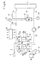
- the dialysis fluid path is shown schematically in FIG. 1a.
- the most important component of this arrangement is the balancing device 1. It comprises two mutually coupled chambers 22 and 23, each chamber 22 or 23 being divided into two spaces 22a, 22b or 23a and 23b by a movable element in the form of a membrane 24 or 25 is.
- These balance chambers are made up of a dialysis fluid source 10, which is provided with a pump, and a metering device 9 fresh dialysis fluid supplied via line 2.
- the space 22a and the space 23a are connected to this feed line 2, a shut-off valve 18 and a shut-off valve 21 being arranged in this feed line 2 for shut-off.
- the valves 14-21 and 30 are controlled by a control device 55.
- the control device has outputs a to h, which are connected to the valves 14-21 via the electrical lines a 'to h'.
- This ultrafiltrate is fed via line 27 and the opened valve 19 to the balancing chamber 22 and there to the room 22b, at the same time fresh dialysis liquid from the room 22a is fed to the room 23a of the balancing chamber 23 via the opened valve 14 and the opened valve 17.
- the used dialysis fluid in the chamber 23b is fed to the outlet 5 via the valve 16.
- the valves 14 to 21 and 30 are actuated by the control device 55 in such a way that the valves 14, 16, 19 and 21 are closed and the valves 15, 17, 18, 20 and 30 are opened (so-called hemodialysis mode).
- This switch position is shown in Fig. 1b. In this valve position, the hemodialysis is then carried out, as is known from DE-PS 28 38 414.
- space 23b is then filled with used dialysis fluid and space 22a with fresh dialysis fluid.
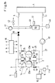
- the air separator 50 is equipped with two sensors, that is to say the upper sensor 51 and the lower sensor 52, which are connected to the inputs i and j of the control device 55 via the electrical lines i 'and j'.
- a single sensor 51 can also be used in combination with a volumetric pump. Since the pressure in the system is known via the dialysis fluid pressure sensor 45, the pump 41 can be controlled by the control unit 55 in such a way that a predetermined amount of dialysis fluid is displaced from the air separator 50, taking into account the general gas equation.
- the dialysis fluid pressure sensor 45 is connected via the electrical line 1 'to the input 1 of the control unit 55.
- valves 14, 16, 17, 19 and 15, 18, 20, 21 are shown dark or light, which should also indicate that these valves have been switched to open or closed by the control device 55.
- the switching position of the valves 14 to 21 corresponds in this case to that of FIG. 1a.
- air is conveyed into the air separator 50 via the bidirectional air pump 41, which is also connected to the control unit 55, whereby the pumping rate is controlled so that the pressure at the dialysis fluid pressure sensor 45 does not rise .
- the pump 41 pumps air until air is detected at the lower sensor 52.
- the sensors 51 and 52 are positioned so that the volume between them corresponds approximately to the balance chamber volume.
- the dialyzing fluid displaced in this case is pumped by the pump 40, the pumping rate of which is matched to that of the air pump 41, via the valve 19 into the space 22b of the balancing chamber 22.
- the respective other pump can be controlled so that the dialysis fluid pressure measured by the dialysis fluid pressure sensor 45 remains constant.
- the fresh dialysis fluid located in the space 22a of the balancing chamber 22 is pumped into the space 23a of the second balancing chamber 23 via the valve 14 and the likewise opened valve 17.
- the dialyzer valve 30 is opened and the valves 14 to 21 by the control unit 55 in the dialysis mode - as mentioned above and shown in FIG. 1b - and the air pump 41 switched to the venting mode.
- the air pump 41 pumps the air in the air separator 50 out of the air separator again for a desired period of time until the upper sensor 51 detects liquid again and deactivates the air pump 41. In this way, continuous ultrafiltration is possible during hemodialysis.
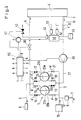
- FIG. 3 A further embodiment is shown in FIG. 3.
- an additional valve 32 is shown in the dialyzer discharge path 13, which connects the output 7 of the dialyzer to the air separator 50, which valve is connected via the line k 'to the input k of the control unit 55.
- this valve 32 is closed by the control unit 55 while the dialysis fluid pump 40 continues to run.
- the air pump 41 is switched off and the ventilation valve 42 of the air separator 50, which is also connected to the control unit 55, is opened. Accordingly, valve 42 is shown dark. This valve 42 remains open until the lower sensor 52 detects air.
- the switching position of the valves 14 to 21 is the same as that shown in FIG. 2. In order to suck in the air as quickly as possible, the pumping rate of the pump 40 can be briefly increased by actuating the control unit 55.
- valve 42 When the desired amount of air is in the air separator 50, the valve 42 is closed and the valves 30 and 32 are opened. At the same time, the valves 14 to 21 are in dialysis mode (see FIG. 1b) switched. At the same time, in this embodiment, the single-acting pump 41 is put into operation by the control unit 55, which pumps the air quantity 50 in the air separator again over a predetermined period of time. This continues until the upper sensor 51 detects liquid again. During this period, ultrafiltrate is withdrawn from the bloodstream due to the resulting negative pressure.
- This arrangement can be controlled particularly precisely if, instead of sensors 51 and 52, an analog level sensor is used. The switching of the valves during hemodialysis and ultrafiltration then corresponds to the switching position already described for FIG. 1a.
Abstract
Es wird ein Verfahren und eine Vorrichtung zur Ultrafiltration bei der Hämodialyse beschrieben, bei der das Ultrafiltrat vor dem Entzug aus dem Dialysatorkreislauf über die Bilanziereinrichtung geführt wird, die gleichzeitig als Ultrafiltratpumpe eingesetzt wird. Hierzu ist eine Steuervorrichtung (55) vorgesehen, die die Zuführ- und Abführventile (14-21) und das Dialysatorventil (30) derart steuert und schaltet, daß die gewünschte Ultrafiltratmenge die dem Füllvolumen einer Bilanzkammer (22, 23) oder einem Mehrfachen davon entspricht, über die Bilanzkammern dem Auslauf (5) zugeführt wird. Zur Durchführung einer kontinuierlichen Ultrafiltration während der Hämodialyse wird dem Dialysierflüssigkeitsweg über den Luftabscheider (50) eine vorher festgelegte Luftmenge zugeführt, die dann während der Hämodialyse über die Pumpe (41) wieder abgepumpt wird, so daß eine entsprechende Menge Ultrafiltrat anfällt.A method and a device for ultrafiltration in hemodialysis are described, in which the ultrafiltrate is passed through the balancing device before being withdrawn from the dialyzer circuit and is used simultaneously as an ultrafiltrate pump. For this purpose, a control device (55) is provided which controls and switches the supply and discharge valves (14-21) and the dialyzer valve (30) in such a way that the desired amount of ultrafiltrate corresponds to the filling volume of a balancing chamber (22, 23) or a multiple thereof , is fed to the outlet (5) via the balance chambers. To carry out a continuous ultrafiltration during hemodialysis, a predetermined amount of air is fed to the dialysis fluid path via the air separator (50), which is then pumped out again during the hemodialysis via the pump (41), so that a corresponding amount of ultrafiltrate is obtained.
Description
Die Erfindung betrifft ein Verfahren zur Hämodiafiltration bei dem die Dialysierflüssigkeit durch eine an den Dialysator angeschlossene mit Absperrventilen versehene und Bilanzkammern aufweisende Bilanziereinrichtung geleitet wird und das Ultrafiltrat in einer genau vorherbestimmten Menge entzogen wird. Die Erfindung betrifft eine Vorrichtung zur Durchführung des Verfahrens.The invention relates to a method for hemodiafiltration in which the dialysis fluid is passed through a balancing device provided with shut-off valves and balancing chambers and connected to the dialyzer, and the ultrafiltrate is withdrawn in a precisely predetermined amount. The invention relates to a device for performing the method.
Aus der DE-PS 28 38 414 ist eine Vorrichtung bekannt, die eine Bilanziereinrichtung aufweist, die aus zwei durch ein verschiebbares Element getrennten Kammern besteht, die je eine Zuführleitung für frische und eine mit einem Auslauf verbundene Abführleitung für gebrauchte Dialysierflüssigkeit aufweist. In den Zuführ- und Abführleitungen sind Absperrventile angeordnet, die von einer Steuereinheit angesteuert und geschaltet werden. Zum Fördern der verbrauchten Dialysierflüssigkeit ist im Dialysierflüssigkeitsweg zwischen Dialysator und Bilanzeinrichtung eine Pumpe angeordnet. Weiterhin sieht diese bekannte Vorrichtung in der Zuführleitung zum Dialysator ein Dialysatorventil und in der Abführleitung des Dialysators einen Luftabscheider vor.From DE-PS 28 38 414 a device is known which has a balancing device which consists of two chambers separated by a displaceable element, each having a supply line for fresh and a discharge line connected to an outlet for used dialysis fluid. Shut-off valves are arranged in the supply and discharge lines, which are controlled and switched by a control unit. A pump is arranged in the dialysis fluid path between the dialyzer and the balance device to convey the used dialysis fluid. Furthermore, this known device provides a dialyzer valve in the supply line to the dialyzer and an air separator in the discharge line of the dialyzer.
Diese Vorrichtung wird derart betrieben, daß frische Dialysierflüssigkeit von einer Dialysierflüssigkeitsquelle den beiden Bilanzkammern abwechselnd durch entsprechende Schaltung der Absperrventile in den Zuführleitungen zugeführt wird. Gleichzeitig wird frische Dialysierflüssigkeit aus einem bereits gefüllten Raum der anderen Bilanzkammer dem Dialysator zugeführt, wo durch Diffusion dem ebenfalls durch den Dialysator fließenden Blut die gewünschten Giftstoffe entzogen werden. Die durch diese Diffusion verbrauchte Dialysierflüssigkeit wird anschließend in den zweiten Raum derselben Bilanzkammer gepumpt, von wo aus die verbrauchte Dialysierflüssigkeit dann in den Auslauf geleitet wird.This device is operated in such a way that fresh dialysis fluid is alternately fed from a dialysis fluid source to the two balancing chambers by appropriate switching of the shut-off valves in the supply lines. At the same time, fresh dialysis fluid is supplied to the dialyzer from an already filled space in the other balancing chamber, where it is also diffused through the dialyzer the desired toxins are withdrawn from flowing blood. The dialysis fluid consumed by this diffusion is then pumped into the second room of the same balancing chamber, from where the used dialysis fluid is then led into the outlet.
Der zwischen der Bilanzeinrichtung und dem Dialysator eingeschlossene Teil des Flüssigkeitkreislaufes verhält sich wie ein geschlossenes, volumenkonstantes System. Um aus diesem System Flüssigkeit abzuführen, ist eine Entnahmevorrichtung vorgesehen, die an einen Ablauf angeschlossen ist.The part of the liquid circuit enclosed between the balance device and the dialyzer behaves like a closed, volume-constant system. In order to discharge liquid from this system, a removal device is provided which is connected to an outlet.
Die mit Hilfe der Entnahmevorrichtung aus dem System abgeleitete Flüssigkeitsmenge muß aufgrund der erwähnten Eigenschaften der Bilanziervorrichtung durch eine gleich große Flüssigkeitsmenge ersetzt werden, die von der Blutseite zur Dialysierflüssigkeitsseite der Dialysatormembran übergeht. Die mittels der Entnahmevorrichtung abgeleitete Flüssigkeitsmenge stimmt also mit der durch die Membran des Dialysators tretenden Flüssigkeitsmenge, dem Ultrafiltrat, überein. Die Entnahmevorrichtung, die im wesentlichen eine Ultrafiltratpumpe aufweist, ist so ausgestaltet, daß eine Steuerung der Ultrafiltration möglich ist.The amount of liquid derived from the system with the aid of the removal device must be replaced due to the properties of the balancing device mentioned by an equal amount of liquid which passes from the blood side to the dialyzing liquid side of the dialyzer membrane. The amount of liquid discharged by means of the removal device thus corresponds to the amount of liquid, the ultrafiltrate, passing through the membrane of the dialyzer. The removal device, which essentially has an ultrafiltrate pump, is designed in such a way that control of the ultrafiltration is possible.
An die Genauigkeit der Bilanziervorrichtung und der Entnahmevorrichtung sind hohe Anforderungen zu stellen. Bei einer Hämodialysebehandlung werden typischerweise etwa 200 l Dialysierlösung durch den Dialysator geleitet. Die Ultrafiltratmenge beträgt typischerweise etwa 2 - 3 l und sollte bis auf eine Abweichung in der Größenordnung 0,1 bis 0,2 l genau bestimmbar sein. Der in der Bilanziereinrichtung verursachte Bilanzierungsfehler darf demnach die Größenordnung von 1 Promille möglichst nicht überschreiten. Um auch eine genau vorherbestimmbare Menge Ultrafiltrat dem Dialysierflüssigkeitsweg mit der erforderlichen Genauigkeit zu entziehen, ist die Entnahmevorrichtung mit einer volumetrischen Membranpumpe ausgerüstet, wobei jeder einzelne Pumpenhub einer Einheitsmenge Ultrafiltrat entspricht. Die Entnahme erfolgt über eine Leitung aus dem unteren Teil eines im Dialysatorkreislauf angeordneten Luftabscheiders, um sicherzustellen, daß nur blasenfreie Flüssigkeit abgeführt wird. Der Ausgang der Ultrafiltrationspumpe bzw. der Entnahmevorrichtung ist über ein Umschaltventil mit der Abflußleitung verbunden.High demands must be placed on the accuracy of the balancing device and the removal device. In a hemodialysis treatment, approximately 200 l of dialysis solution are typically passed through the dialyzer. The amount of ultrafiltrate is typically about 2-3 l and should be able to be determined with a deviation of the order of 0.1 to 0.2 l. The accounting error caused in the balancing facility may therefore be the If possible, do not exceed the order of 1 per mille. In order to extract a precisely predeterminable amount of ultrafiltrate from the dialysis fluid path with the required accuracy, the removal device is equipped with a volumetric diaphragm pump, each individual pump stroke corresponding to a unit amount of ultrafiltrate. The removal takes place via a line from the lower part of an air separator arranged in the dialyzer circuit in order to ensure that only bubble-free liquid is discharged. The output of the ultrafiltration pump or the extraction device is connected to the drain line via a changeover valve.
Obwohl diese bekannte Vorrichtung genau und zuverlässig funktioniert, besteht dennoch das Bedürfnis, Geräte dieser Art technisch zu vereinfachen, d.h. insbesondere die Zahl der aktiven Komponenten zu vermindern und Kalibriervorgänge und sicherheitstechnische Kontrollen, die von Zeit zu Zeit durchgeführt werden müssen, einzusparen. Diese Kalibriervorgänge und Kontrollen betreffen auch die Entnahmevorrichtung für das Ultrafiltrat.Although this known device works accurately and reliably, there is still a need to technically simplify devices of this type, i.e. in particular to reduce the number of active components and to save calibration procedures and safety checks that have to be carried out from time to time. These calibration processes and controls also concern the removal device for the ultrafiltrate.
Aufgabe der Erfindung ist daher ein Verfahren, mit dem eine vorher bestimmbare Ultrafiltration auf einfachere Weise ohne zusätzliche Ultrafiltratpumpe durchgeführt werden kann. Es ist auch Aufgabe der Erfindung, eine Vorrichtung zur Durchführung dieses Verfahrens bereitzustellen.The object of the invention is therefore a method with which a previously determinable ultrafiltration can be carried out in a simpler manner without an additional ultrafiltrate pump. It is also an object of the invention to provide an apparatus for performing this method.
Diese Aufgabe wird durch den kennzeichnenden Teil von Anspruch 1 sowie den kennzeichnenden Teil des Anspruchs 8 gelöst.This object is achieved by the characterizing part of
Während bisher das Ultrafiltrat über eine separate Entnahmevorrichtung im Dialysierflüssigkeitsweg zwischen Dialysatorausgang und Bilanziereinrichtung entnommen wurde, wird erfindungsgemäß das Ultrafiltrat vor dem Abführen aus dem Dialysatorkreislauf zunächst über die Bilanziereinrichtung geführt. Auf diese Weise kann die gesamte Entnahmeeinrichtung für das Ultrafiltrat eingespart werden. Von der Bilanziereinrichtung wird dann das Ultrafiltrat ebenso wie die verbrauchte Dialysierflüssigkeit dem Auslauf zugeführt. Neben der Einsparung der Ultrafiltratpumpe bietet dieses Verfahren weiterhin den Vorteil, daß das Füllvolumen der Bilanzkammern zur Bestimmung der Ultrafiltratmenge eingesetzt werden kann. Da das Füllvolumen einer Bilanzkammer üblicherweise 30 ml umfaßt, kann durch mehrmaliges periodisches Füllen der Bilanzkammer mit Ultrafiltrat die gewünschte Ultrafiltratmenge, die 2 - 3 l beträgt, auf exakte Weise bestimmt und dem Dialysierflüssigkeitsweg entzogen werden.While previously the ultrafiltrate was removed via a separate removal device in the dialysis fluid path between the dialyzer outlet and the balancing device, the ultrafiltrate is first passed over the balancing device before being discharged from the dialyzer circuit. In this way, the entire removal device for the ultrafiltrate can be saved. The ultrafiltrate and the used dialysis fluid are then fed to the outlet from the balancing device. In addition to saving the ultrafiltrate pump, this method also has the advantage that the filling volume of the balancing chambers can be used to determine the amount of ultrafiltrate. Since the filling volume of a balancing chamber usually comprises 30 ml, the desired amount of ultrafiltrate, which amounts to 2-3 l, can be determined in an exact manner and removed from the dialysis fluid path by repeatedly filling the balancing chamber with ultrafiltrate several times.
Gemäß einer ersten Ausführungsform werden zur Durchführung der Ultrafiltration die Absperrventile in den Zuführ- und Abführleitungen der Bilanzkammern zunächst so geschaltet, daß eine Bilanzkammer vollständig mit frischer Dialysierflüssigkeit und die andere Bilanzkammer vollständig mit verbrauchter Dialysierflüssigkeit gefüllt ist. Dann wird der Dialysierflüssigkeitsweg zwischen der Bilanziereinrichtung und dem Dialysator unterbrochen. Dies geschieht zweckmäßigerweise mittels des sogenannten Dialysatorventils. Nachdem dieses Dialysatorventil geschlossen worden ist, wird mittels der Dialysierflüssigkeitspumpe weiterhin verbrauchte Dialysierflüssigkeit aus dem Dialysator gepumpt, wobei sich nach relativ kurzer Zeit aufgrund des unterbrochenen Zuflusses von frischer Dialysierflüssigkeit in der Dialysatorkammer ein Unterdruck einstellt. Dadurch wird dem Blut Flüssigkeit, das sog. Ultrafiltrat, entzogen, das nunmehr von der Dialysierflüssigkeitspumpe in den Raum der Bilanzkammer gepumpt wird, deren zweiter Raum mit frischer Dialysierflüssigkeit gefüllt ist. Da durch die Unterbrechung des Dialysierflüssigkeitsweges die verdrängte frische Dialysierflüssigkeit nicht dem Dialysator zugeführt werden kann, wird durch geeignete Schaltung der Zuführ- und Abführventile der Bilanzkammern die frische Dialysierflüssigkeit in den leeren Raum der anderen Bilanzkammer umgelenkt, wodurch gleichzeitig die in dieser Kammer befindliche verbrauchte Dialysierflüssigkeit zum Auslauf befördert wird. Nachdem die erste Bilanzkammer vollständig mit Ultrafiltrat gefüllt worden ist, ist der erste Durchgang der Ultrafiltration beendet und die Zuführ- und Abführventile der Bilanzkammern werden wieder auf Hämodialysebetrieb geschaltet. Durch Unterbrechung der Hämodialyse kann auf diese Weise jeweils ein Ultrafiltratzyklus eingeschoben werden.According to a first embodiment, in order to carry out the ultrafiltration, the shut-off valves in the feed and discharge lines of the balance chambers are first switched so that one balance chamber is completely filled with fresh dialysis fluid and the other balance chamber is completely filled with used dialysis fluid. Then the dialysis fluid path between the balancing device and the dialyzer is interrupted. This is expediently done by means of the so-called dialyzer valve. After this dialyzer valve has been closed, used dialyzing fluid is pumped out of the dialyzer by means of the dialyzing fluid pump, a negative pressure being established in the dialyzer chamber after a relatively short time due to the interrupted inflow of fresh dialyzing fluid. This gets the blood Liquid, the so-called ultrafiltrate, withdrawn, which is now pumped by the dialysis liquid pump into the space of the balancing chamber, the second space of which is filled with fresh dialysis liquid. Since the displaced fresh dialysis fluid cannot be supplied to the dialyzer by interrupting the dialysis fluid path, the fresh dialysis fluid is redirected into the empty space of the other balance chamber by suitable switching of the supply and discharge valves of the balance chambers, whereby at the same time the used dialysis fluid located in this chamber Spout is transported. After the first balancing chamber has been completely filled with ultrafiltrate, the first pass of ultrafiltration has ended and the feed and discharge valves of the balancing chambers are switched back to hemodialysis mode. By interrupting the hemodialysis, an ultrafiltrate cycle can be inserted in this way.
Dieses Verfahren, das den ungleichmäßigen Entzug von Ultrafiltrat bewirkt, kann gemäß einer weiteren Ausführungsform dahingehend verbessert werden, daß das Ultrafiltrat kontinuierlich entzogen wird. Hierzu wird dem Dialysierflüssigkeitsweg vor der Durchführung von Ultrafiltration und Hämodialyse eine solche Menge Luft zugeführt, die dem Füllvolumen der Bilanziereinrichtung oder einem Mehrfachen entspricht. Die gewünschte Luftmenge wird in den üblicherweise zwischen dem Dialysator und der Bilanziereinrichtung im Dialysierflüssigkeitsweg angeordneten Luftabscheider eingeleitet. Hierbei wird ebenfalls der Dialysierflüssigkeitsweg so lange unterbrochen, bis die gewünschte Luftmenge sich im Luftabscheider befindet.This method, which causes the uneven withdrawal of ultrafiltrate, can be improved in a further embodiment in that the ultrafiltrate is continuously withdrawn. For this purpose, an amount of air which corresponds to the filling volume of the balancing device or a multiple thereof is supplied to the dialysis fluid path before carrying out ultrafiltration and hemodialysis. The desired amount of air is introduced into the air separator which is usually arranged between the dialyzer and the balancing device in the dialysis fluid path. The dialysis fluid path is also interrupted until the desired amount of air is in the air separator.
Die Luftzufuhr kann auf zweierlei Weise durchgeführt werden. Gemäß einer bevorzugten Ausführungsform ist an den Luftabscheider eine Luftpumpe angeschlossen, die nach Unterbrechung des Dialysierflüssigkeitswegs zwischen der Bilanzierreinrichtung und dem Dialysator durch Schließen des Dialysatorventils die gewünschte Luftmenge in den Luftabscheider pumpt. Hierbei bleibt die Dialysierflüssigkeitspumpe ebenfalls in Betrieb. Durch geeignete Abstimmung der Förderraten der beiden Pumpen wird ein Druckanstieg im Dialysierflüssigkeitsweg vermieden. Im Luftabscheider sind zwei im Abstand angeordnete Sensoren oder ein analoger Füllstandsmesser derart angeordnet, daß die beiden Sensoren bzw. die Minimal- und Maximalstellung des Füllstandssensors etwa das Füllvolumen einer Bilanzierkammer einschließen. Während dieses Vorgangs wird also keine Flüssigkeit aus dem Blut entzogen, sondern das geschlossene System kontrolliert teilweise mit Luft gefüllt. Dieser Vorgang erfordert nur wenige Sekunden Zeit. Anschließend werden die Ventile wieder in den Dialysemodus geschaltet und die Luftpumpe beginnt nun in umgekehrter Richtung zu arbeiten, um die zuvor in den Dialysierflüssigkeitsweg gepumpte Luft wieder aus dem Luftabscheider zu entfernen, wodurch eine Ultrafiltration von Flüssigkeit aus dem Blut hervorgerufen wird. Für den Fall, daß sich im Luftabscheider während der Hämodialyse zusätzliche Luft ansammeln sollte, bleibt die Luftpumpe so lange in Betrieb, bis der obere Sensor Flüssigkeit detektiert.The air supply can be carried out in two ways. According to a preferred embodiment, an air pump is connected to the air separator and, after interrupting the dialysis fluid path between the balancing device and the dialyzer, pumps the desired amount of air into the air separator by closing the dialyzer valve. The dialysis fluid pump also remains in operation. A suitable increase in the delivery rates of the two pumps prevents an increase in pressure in the dialysis fluid path. In the air separator, two sensors arranged at a distance or an analog level meter are arranged in such a way that the two sensors or the minimum and maximum positions of the level sensor approximately enclose the filling volume of a balancing chamber. During this process, no liquid is drawn from the blood, but the closed system is partially filled with air in a controlled manner. This process takes only a few seconds. The valves are then switched back to dialysis mode and the air pump now begins to work in the reverse direction in order to remove the air previously pumped into the dialysis fluid path from the air separator, which causes ultrafiltration of fluid from the blood. In the event that additional air should collect in the air separator during hemodialysis, the air pump remains in operation until the upper sensor detects liquid.
Gemäß einer weiteren Ausführungsform besteht auch die Möglichkeit, anstatt mit Hilfe einer Luftpumpe mittels der Dialysierflüssigkeitspumpe, die zwischen dem Luftabscheider und der Bilanziereinrichtung angeordnet ist, die Luft in den Dialysierflüssigkeitsweg zu pumpen. Hierzu wird der Dialysierflüssigkeitsweg zwischen dem Ausgang des Dialysators und dem Luftabscheider mittels eines weiteren Ventils unterbrochen, um gegebenenfalls ein Ansaugen verbrauchter Dialysierflüssigkeit zu verhindern. Wenn in diesem Fall die Dialysierflüssigkeitspumpe weiterbetrieben wird, wird durch den Luftabscheider ebenfalls Luft in den Luftabscheider gesaugt. Zur Beschleunigung des Ansaugens kann die Pumpleistung der Dialysierflüssigkeitspumpe kurzzeitig erhöht werden. Zu diesem Zweck wird auch die Dialysierflüssigkeitspumpe von der Steuereinheit entsprechend geschaltet. Die Bestimmung der Luftmenge erfolgt dann ebenfalls über die beiden im Luftabscheider angeordneten Sensoren bzw. über den analogen Füllstandsmesser. Danach wird der Dialysierflüssigkeitsweg wieder geöffnet und die Ventile auf Dialysebetrieb geschaltet. Auch in diesem Fall wird anschließend während der Dialyse mittels der an den Luftabscheider angeschlossenen Luftpumpe die zuvor angesaugte Luftmenge wieder dem Dialysierflüssigkeitsweg entzogen. Dadurch steigt der Flüssigkeitsspiegel im Luftabscheider wieder an, und nachdem beide Sensoren Flüssigkeit detektieren ist die Ultrafiltration abgeschlossen, wobei eine dem Luftvolumen entsprechende Ultrafiltratmenge gewonnen wurde. Danach wird der Dialysierflüssigkeitsweg wieder mit Luft gefüllt und der Vorgang beginnt von neuem. Auf diese Weise ist es möglich, während der Dialyse kontinuierlich Ultrafiltrat zu entziehen.According to a further embodiment, there is also the possibility, instead of with the aid of an air pump, by means of the dialysis liquid pump, which is between the air separator and the balancing device is arranged to pump the air into the dialysis fluid path. For this purpose, the dialysis fluid path between the outlet of the dialyzer and the air separator is interrupted by means of a further valve in order to prevent used dialysis fluid from being sucked in, if necessary. In this case, if the dialysis liquid pump continues to be operated, air is also sucked into the air separator by the air separator. The pumping capacity of the dialysis fluid pump can be briefly increased to accelerate the suction. For this purpose, the dialysis fluid pump is also switched accordingly by the control unit. The amount of air is then also determined via the two sensors arranged in the air separator or via the analog level meter. The dialysis fluid path is then opened again and the valves switched to dialysis mode. In this case too, the amount of air previously drawn in is then withdrawn again from the dialysis fluid path during dialysis by means of the air pump connected to the air separator. As a result, the liquid level in the air separator rises again, and after both sensors detect liquid, the ultrafiltration is completed, an amount of ultrafiltrate corresponding to the air volume being obtained. Then the dialysis fluid path is filled with air again and the process begins again. In this way it is possible to continuously withdraw ultrafiltrate during dialysis.
Der Entzug der gewünschten Ultrafiltratmenge kann durch geeignete Steuerung der Luftpumpe auf beliebig viele Füllzyklen der Bilanzkammern verteilt werden. Durch geeignete Wahl des Kammervolumens des Luftabscheiders kann dieser das Mehrfache des Füllvolumens einer Bilanzkammer umfassen, so daß im Extremfall, wenn das Volumen des Luftabscheiders zwei bis drei Liter entspricht, dieser nur ein Mal mit Luft gefüllt werden muß.Withdrawal of the desired amount of ultrafiltrate can be done at will by suitable control of the air pump many filling cycles of the balancing chambers are distributed. By a suitable choice of the chamber volume of the air separator, this can comprise a multiple of the filling volume of a balancing chamber, so that in extreme cases, if the volume of the air separator corresponds to two to three liters, it only has to be filled with air once.
Bei dem kontinuierlichen Entzug von Ultrafiltrat während der Dialyse ist die Flüssigkeitsmenge, die den Dialysator verläßt, um den Anteil des Ultrafiltrats vergrößert gegenüber der Menge, die an frischer Dialysierflüssigkeit dem Dialysator zugeführt wird. Da dieser zusätzliche Anteil durch den Entzug der Luft im Luftabscheider angesammelt wird, ändert sich gegenüber den bekannten Dialyseverfahren an der Arbeitsweise der Bilanzkammern nichts. Beim Ansaugen der Luft in den Luftabscheider wird die darin befindliche verbrauchte Dialysierflüssigkeit in den leeren Raum der Bilanzkammer gepumpt, die mit frischer Dialysierflüssigkeit gefüllt ist, wobei gleichzeitig diese frische Dialysierflüssigkeit in die andere Bilanzkammer gedrückt wird, wo wiederum die darin befindliche verbrauchte Dialysierflüssigkeit in den Auslauf verdrängt wird. Dies wird durch entsprechende Steuerung der Zuführ- und Abführventile erreicht.When ultrafiltrate is continuously withdrawn during dialysis, the amount of liquid leaving the dialyzer is increased by the amount of ultrafiltrate compared to the amount of fresh dialyzing liquid supplied to the dialyzer. Since this additional portion is accumulated in the air separator through the removal of air, nothing changes in the way the balance chambers work compared to the known dialysis processes. When the air is sucked into the air separator, the used dialysis fluid contained therein is pumped into the empty space of the balancing chamber, which is filled with fresh dialysis fluid, at the same time this fresh dialysis fluid is pressed into the other balancing chamber, where the used dialysis fluid contained therein is in turn discharged is ousted. This is achieved by controlling the supply and discharge valves accordingly.
Die erfindungsgemäße Vorrichtung weist keine Entnahmevorrichtung und somit keine Ultrafiltratpumpe auf. Der Ausgang des Dialysators ist in diesem Fall direkt mit dem Luftabscheider verbunden, der wiederum über die Dialysierflüssigkeitspumpe mit der Bilanziereinrichtung verbunden ist. Erfindungsgemäß wird die Steuereinrichtung zur Steuerung der Zuführ- und Abführventile der Bilanziereinrichtung sowie des Dialysatorventils und ggf. des zusätzlichen Absperrventils zwischen Dialysatorausgang und Luftabscheider so ausgebildet, daß das Ultrafiltrat in der vorher bestimmten Menge jeweils über eine Kammer der Bilanziereinrichtung zum Auslauf führbar ist. Hierbei werden die Absperrventile derart gesteuert, daß die abgeführte Ultrafiltratmenge jeweils einem Füllvolumen einer Bilanzkammer oder einem Mehrfachen entspricht.The device according to the invention has no removal device and thus no ultrafiltrate pump. In this case, the output of the dialyzer is connected directly to the air separator, which in turn is connected to the balancing device via the dialysis fluid pump. According to the invention, the control device for controlling the supply and discharge valves of the balancing device and the Dialyzer valve and possibly the additional shut-off valve between the dialyzer outlet and the air separator are designed so that the ultrafiltrate can be fed to the outlet in the predetermined amount via a chamber of the balancing device. The shut-off valves are controlled in such a way that the amount of ultrafiltrate discharged corresponds in each case to a filling volume of a balancing chamber or a multiple.
Gemäß einer ersten Ausführungsform ist die Steuereinrichtung derart ausgebildet, daß sie zwischen zwei Hämodialysezyklen das Dialysatorventil schließt und die Absperrventile der Bilanziereinrichtung derart ansteuert, daß Ultrafiltrat in einen der beiden Räume einer der beiden Bilanzkammern mittels der Dialysierflüssigkeitspumpe gefördert werden kann, während die im anderen Raum dieser Bilanzkammer befindliche frische Dialysierflüssigkeit in die andere Bilanzkammer umgeleitet wird. Dies bedeutet, daß abwechselnd die Ventile zwischen Ultrafiltratmodus und Hämodialysemodus hin- und hergeschaltet werden. Unter Hämodialysemodus wird verstanden, daß die Ventile in den Zuführleitungen beispielsweise der beiden jeweils rechten Räume der Bilanzkammern und die Ventile der Abführleitungen der beiden jeweils linken Räume der Bilanzkammern geschlossen sind, während die Ventile in den Zuführ- und Abführleitungen der übrigen Räume geschlossen sind.According to a first embodiment, the control device is designed such that it closes the dialyzer valve between two hemodialysis cycles and controls the shut-off valves of the balancing device in such a way that ultrafiltrate can be conveyed into one of the two rooms of one of the two balancing chambers by means of the dialysis liquid pump, while the other room Fresh dialysis fluid located in the balance chamber is diverted to the other balance chamber. This means that the valves are alternately switched back and forth between ultrafiltrate mode and hemodialysis mode. Hemodialysis mode is understood to mean that the valves in the supply lines of, for example, the two right-hand rooms of the balance chambers and the valves of the discharge lines of the two left-hand rooms of the balance chambers are closed, while the valves in the supply and discharge lines of the other rooms are closed.
Beim Übergang zum Ultrafiltratmodus werden alle Ventile einer der beiden Bilanzkammern umgeschaltet, während bei der anderen Bilanzkammer lediglich die Ventile des linken Raumes umgeschaltet werden und die des rechten Raumes beibehalten werden.When switching to ultrafiltrate mode, all valves in one of the two balancing chambers are switched over, while in the other balancing chamber only the valves in the left room are switched over and those in the right room are retained.
Gemäß einer weiteren Ausführungsform ist die Steuereinheit zusätzlich zur Steuerung der Luftpumpe und/oder der Dialysierflüssigkeitspumpe ausgebildet. Die Schaltstellung der Ventile im Hämodialysemodus entspricht der in der oben beschriebenen Ausführungsform. Nach einem Hämodialysezyklus, bei dem auch gleichzeitig das Ultrafiltrat entzogen wird, werden die Ventile in den oben beschriebenen Ultrafiltratmodus geschaltet, der jetzt allerdings dazu dient, Luft in den Dialysierflüssigkeitsweg zu pumpen. Zu diesem Zweck steuert die Steuereinheit nicht nur die Absperrventile sondern auch die Luftpumpe und die Dialysierflüssigkeitspumpe sowie gegebenenfalls auch das weitere Absperrventil im Dialysierflüssigkeitsweg zwischen Dialysator und Luftabscheider an.According to a further embodiment, the control unit is additionally designed to control the air pump and / or the dialysis fluid pump. The switching position of the valves in the hemodialysis mode corresponds to that in the embodiment described above. After a hemodialysis cycle in which the ultrafiltrate is also withdrawn at the same time, the valves are switched to the ultrafiltrate mode described above, which, however, now serves to pump air into the dialysis fluid path. For this purpose, the control unit not only controls the shut-off valves but also the air pump and the dialysis fluid pump and possibly also the additional shut-off valve in the dialysis fluid path between the dialyzer and air separator.
Um eine kontinuierliche Ultrafiltration durchzuführen, ist der Luftabscheider be- und entlüftbar ausgebildet. Gemäß einer besonderen Ausführungsform ist der Luftabscheider mit einer bidirektional arbeitenden Luftpumpe ausgestattet, die vor der Ultrafiltration die entsprechende Luftmenge in den Luftabscheider hineinpumpt und während der Ultrafiltration diese Luftmenge wieder aus dem Luftabscheider abpumpt. Damit das jeweilige Luftvolumen exakt bestimmt werden kann, sind am Luftabscheider zwei Sensoren derart im Abstand angeordnet, daß sie das Füllvolumen einer Bilanzkammer oder ein Vielfaches davon eingrenzen. Es ist auch möglich, anstelle dieser beiden Sensoren einen analog arbeitenden Füllstandsmesser einzubauen, dessen Abstand zwischen Maximal- und Minimalstellung ebenfalls einem Füllvolumen oder einem Mehrfachen des Füllvolumens einer Bilanzkammer entspricht.In order to carry out continuous ultrafiltration, the air separator is designed so that it can be aerated and vented. According to a special embodiment, the air separator is equipped with a bidirectional air pump which pumps the corresponding amount of air into the air separator before ultrafiltration and pumps this amount of air out of the air separator again during ultrafiltration. So that the respective air volume can be determined exactly, two sensors are arranged on the air separator in such a distance that they limit the filling volume of a balancing chamber or a multiple thereof. It is also possible to use these two sensors instead to install an analog level meter, the distance between maximum and minimum position also corresponds to a filling volume or a multiple of the filling volume of a balancing chamber.
Im Dialysierflüssigkeitsweg ist gemäß einer weiteren Ausführungsform außer dem Dialysatorventil zwischen dem Ausgang des Dialysators und dem Eingang des Luftabscheiders ein weiteres Ventil angeordnet.According to a further embodiment, a further valve is arranged in the dialysis fluid path in addition to the dialyzer valve between the outlet of the dialyzer and the inlet of the air separator.
Beispielhafte Ausführungsformen der Erfindung werden nachfolgend anhand der Zeichnung näher erläutert.Exemplary embodiments of the invention are explained in more detail below with reference to the drawing.
Es zeigen :
- Fig. 1 a,b, vereinfachte Prinzipschemata des Dialysierflüssigkeitswegs mit einer Bilanziereinrichtung gemäß einer ersten Ausführungsform;
- Fig.2 ebenfalls ein vereinfachtes Prinzipschema des Dialysierflüssigkeitswegs gemäß einer weiteren Ausführungsform;
- Fig.3 ebenfalls ein vereinfachtes Prinzipschema des Dialysierflüssigkeitswegs gemäß einer weiteren Ausführungsform.
- 1 a, b, simplified schematic diagrams of the dialysis fluid path with a balancing device according to a first embodiment;
- 2 also shows a simplified schematic diagram of the dialysis fluid path according to a further embodiment;
- 3 also shows a simplified schematic diagram of the dialysis fluid path according to a further embodiment.
In der Fig. 1a ist der Dialysierflüssigkeitsweg schematisch dargestellt. Wichtigster Bestandteil dieser Anordnung ist die Bilanziervorrichtung 1. Sie umfaßt zwei miteinander gekoppelte Kammern 22 und 23, wobei jede Kammer 22 bzw. 23 durch ein bewegliches Element in Gestalt einer Membrane 24 bzw. 25 in zwei Räume 22a, 22b bzw. 23a und 23b unterteilt ist. Diese Bilanzkammern werden aus einer Dialysierflüssigkeitsquelle 10, die mit einer Pumpe versehen ist, sowie einer Dosiervorrichtung 9 mit frischer Dialysierflüssigkeit über die Leitung 2 versorgt. In dem hier gezeigten Beispiel ist der Raum 22a und der Raum 23a an diese Zuführleitung 2 angeschlossen, wobei zum Absperren jeweils ein Absperrventil 18 und ein Absperrventil 21 in dieser Zuführleitung 2 angeordnet ist. Diese Räume 22a, 23a der beiden Bilanzkammern 22 und 23 sind an ihrer Auslaßseite über weitere Absperrventile 14 bzw. 17 mit dem Dialysatorzuleitungszweig 6 verbunden, der zum Dialysator 4 führt. Zu diesem Zuleitungszweig 6 ist ein Dialysatorventil 30 eingeschaltet. Der Ausgang des Dialysators 4 ist über den Dialysatorableitungszweig 13, einen Luftabscheider 50 und eine Dialysierflüssigkeitsdruckmeßeinrichtung 45 sowie eine an den Luftabscheider 50 angeschlossene Dialysierflüssigkeitspumpe 40 wiederum mit der Bilanziereinrichtung 1 verbunden. Der Dialysierflüssigkeitsableitungszweig 27 zwischen der Dialysierflüssigkeitspumpe 14 und der Bilanziereinrichtung 1 teilt sich in zwei Leitungswege auf, die zu den Räumen 22b und 23b der Bilanzkammern 22 und 23 führen. In diesen beiden Leitungswegen sind vor den Bilanzkammern Absperrventile 19 und 20 angeordnet. Die Räume 22b und 23b sind über Absperrventile 15 und 16 mit der Ablaufleitung 3 verbunden, die zum Auslauf 5 führt.The dialysis fluid path is shown schematically in FIG. 1a. The most important component of this arrangement is the
Die Ventile 14-21 und 30 werden von einer Steuereinrichtung 55 angesteuert. Zu diesem Zweck weist die Steuereinrichtung Ausgänge a bis h auf, die mit den Ventilen 14 - 21 über die elektrischen Leitungen a′ bis h′ verbunden sind.The valves 14-21 and 30 are controlled by a
In der Fig. 1a sind die Ventile 14, 16, 17 und 19 dunkel (d.h. geöffnet) und die Ventile 15, 18, 20, 21 und das Dialysatorventil 30 hell (d.h. geschlossen) dargestellt. Diese Schaltsituation (sog. Ultrafiltratmodus) entspricht der ersten Ausführungsform des erfindungsgemäßen Verfahrens, bei der der Raum 22a vollständig mit frischer Dialysierflüssigkeit gefüllt ist und der Raum 23b vollständig mit verbrauchter Dialysierflüssigkeit. Wenn nun die Dialysierflüssigkeitspumpe 40 bei geschlossenem Dialysatorventil 30 in Betrieb ist, entsteht im Dialysator 4 ein Unterdruck, wodurch Ultrafiltrat dem Blutkreisweg (nicht dargestellt) entzogen wird. Dieses Ultrafiltrat wird über die Leitung 27 und das geöffnete Ventil 19 der Bilanzkammer 22 und dort dem Raum 22b zugeführt, wobei gleichzeitig frische Dialysierflüssigkeit aus dem Raum 22a über das geöffnete Ventil 14 und das geöffnete Ventil 17 dem Raum 23a der Bilanzkammer 23 zugeführt wird. Hierbei wird die in der Kammer 23b befindliche verbrauchte Dialysierflüssigkeit über das Ventil 16 dem Ablauf 5 zugeführt. Nachdem der Raum 22b der Bilanzkammer 22 vollständig mit Ultrafiltrat gefüllt ist, werden die Ventile 14 bis 21 und 30 von der Steuereinrichtung 55 derart angesteuert, daß die Ventile 14, 16, 19 und 21 geschlossen werden und die Ventile 15, 17, 18, 20 und 30 geöffnet werden (sog. Hämodialysemodus). Diese Schaltstellung ist in der Fig. 1b dargestellt. Bei dieser Ventilstellung wird dann die Hämodialyse durchgeführt, wie es aus der DE-PS 28 38 414 bekannt ist. Bei dem nachfolgenden Dialysezyklus wird dann der Raum 23b mit verbrauchter und der Raum 22a mit frischer Dialysierflüssigkeit gefüllt.1a, the
Für den Fall, daß sich in dem Dialysierflüssigkeitsweg im Luftabscheider 50 Luft abscheidet, fällt der Flüssigkeitsspiegel, so daß ein am Luftabscheider 50 angeordneter Luft/Flüssigkeitssensor 51 Luft detektiert. In diesem Fall wird die Pumpe 41 in Betrieb genommen, die dann die überflüssige Luft abpumpt, bis sie auf ein Signal des Sensors 51 hin desaktiviert wird.In the event that air separates in the dialysis liquid path in the
In der Fig. 2 ist eine weitere Ausführungsform dargestellt. In diesem Fall ist der Luftabscheider 50 mit zwei Sensoren, also oberem Sensor 51 und unterem Sensor 52 ausgestattet, die über die elektrischen Leitungen i′ und j′ mit den Eingängen i und j der Steuereinrichtung 55 verbunden sind. Anstelle eines analog arbeitenden Füllstandssensor bzw. anstelle zweier Sensoren 51, 52 kann auch ein einziger Sensor 51 in Kombination mit einer volumetrisch arbeitenden Pumpe eingesetzt werden. Da über den Dialysierflüssigkeitsdrucksensor 45 der Druck im System bekannt ist, kann die Pumpe 41 durch die Steuereinheit 55 so gesteuert werden, daß unter Berücksichtigung der allgemeinen Gasgleichung eine vorher bestimmbare Menge Dialysierflüssigkeit aus dem Luftabscheider 50 verdrängt wird. Zu diesem Zweck ist der Dialysierflüssigkeitsdrucksensor 45 über die elektrische Leitung 1′ mit dem Eingang 1 der Steuereinheit 55 verbunden.A further embodiment is shown in FIG. 2. In this case, the
Die Ventile 14, 16, 17, 19 bzw. 15, 18, 20, 21 sind dunkel bzw. hell dargestellt, was ebenfalls andeuten soll, daß diese Ventile von der Steuereinrichtung 55 auf offen bzw. geschlossen geschaltet worden sind. Die Schaltstellung der Ventile 14 bis 21 entspricht in diesem Fall der von Fig. 1a.The
Vor Beginn der Ultrafiltration wird gemäß der hier gezeigten Ausführungsform zunächst über die als bidirektional arbeitende Luftpumpe 41, die ebenfalls an die Steuereinheit 55 angeschlossen ist, Luft in den Luftabscheider 50 gefördert, wobei die Pumprate so kontrolliert wird, daß der Druck am Dialysierflüssigkeitsdrucksensor 45 nicht ansteigt. Die Pumpe 41 fördert so lange Luft, bis Luft am unteren Sensor 52 detektiert wird. Die Sensoren 51 und 52 sind so positioniert, daß das zwischen ihnen liegende Volumen etwa dem Bilanzkammervolumen entspricht.Before the start of ultrafiltration, air is conveyed into the
Die hierbei verdrängte Dialysierflüssigkeit wird von der Pumpe 40, deren Pumprate auf die der Luftpumpe 41 abgestimmt ist, über das Ventil 19 in den Raum 22b der Bilanzkammer 22 gepumpt. Bei vorgegebener Geschwindigkeit, entweder der Pumpe 40 oder der Pumpe 41, kann die jeweils andere Pumpe so gesteuert werden, daß der über den Dialysierflüssigkeitsdrucksensor 45 gemessene Dialysierflüssigkeitsdruck konstant bleibt.The dialyzing fluid displaced in this case is pumped by the
Gleichzeitig wird die im Raum 22a der Bilanzkammer 22 befindliche frische Dialysierflüssigkeit über das Ventil 14 und das ebenfalls geöffnete Ventil 17 in den Raum 23a der zweiten Bilanzkammer 23 gepumpt.At the same time, the fresh dialysis fluid located in the
Nachdem die gewünschte Luftmenge in den Luftabscheider 50 gepumpt worden ist, werden das Dialysatorventil 30 geöffnet und die Ventile 14 bis 21 von der Steuereinheit 55 in den Dialysemodus - wie vorstehend erwähnt und in Fig. 1b gezeigt ist - und die Luftpumpe 41 in den Entlüftungsbetrieb geschaltet. Dabei pumpt die Luftpumpe 41 über einen gewünschten Zeitraum die im Luftabscheider 50 befindliche Luft wieder aus dem Luftabscheider ab, bis der obere Sensor 51 wiederum Flüssigkeit detektiert und die Luftpumpe 41 desaktiviert. Auf diese Weise ist eine kontinuierliche Ultrafiltration während der Hämodialyse möglich.After the desired amount of air has been pumped into the
In der Fig. 3 ist eine weitere Ausführungsform dargestellt. In diesem Beispiel ist in dem Dialysatorableitungsweg 13, der den Ausgang 7 des Dialysators mit dem Luftabscheider 50 verbindet, ein zusätzliches Ventil 32 eingezeichnet, das über die Leitung k′ mit dem Eingang k der Steuereinheit 55 verbunden ist. Vor Beginn der Ultrafiltration wird, um ein Ansaugen von verbrauchter Dialysierflüssigkeit zu verhindern, dieses Ventil 32 von der Steuereinheit 55 geschlossen, während die Dialysierflüssigkeitspumpe 40 weiterläuft. Gleichzeitig ist die Luftpumpe 41 abgeschaltet und das Belüftungsventil 42 des Luftabscheiders 50, das ebenfalls an die Steuereinheit 55 angeschlossen ist, geöffnet. Dementsprechend ist Ventil 42 dunkel dargestellt. Dieses Ventil 42 bleibt so lange geöffnet, bis der untere Sensor 52 Luft detektiert. Die Schaltstellung der Ventile 14 bis 21 ist die gleiche wie die, die in der Fig. 2 dargestellt ist. Um die Luft möglichst schnell anzusaugen, kann die Pumprate der Pumpe 40 durch Ansteuerung der Steuereinheit 55 kurzzeitig erhöht werden.A further embodiment is shown in FIG. 3. In this example, an
Wenn sich die gewünschte Luftmenge im Luftabscheider 50 befindet, wird das Ventil 42 geschlossen und die Ventile 30 und 32 geöffnet. Gleichzeitig werden die Ventile 14 bis 21 in den Dialysemodus (s. Fig. 1b) geschaltet. Gleichzeitig wird in dieser Ausführungsform die einseitig wirkende Pumpe 41 von der Steuereinheit 55 in Betrieb genommen, die über einen vorher bestimmten Zeitraum die im Luftabscheider befindliche Luftmenge 50 wieder abpumpt. Dies geschieht so lange, bis der obere Sensor 51 wieder Flüssigkeit detektiert. Während dieses Zeitraumes wird durch den entstehenden Unterdruck Ultrafiltrat dem Blutweg entzogen. Diese Anordnung ist besonders präzise steuerbar, wenn anstelle der Sensoren 51 und 52 ein anlog arbeitender Füllstandssensor eingesetzt wird. Die Schaltung der Ventile während der Hämodialyse und der Ultrafiltration entspricht dann der bereits zu Figur 1a beschriebenen Schaltstellung.When the desired amount of air is in the
Claims (15)
daß das Ultrafiltrat aus dem Dialysierflüssigkeitsweg über die Bilanziereinrichtung kontrolliert abgeführt wird, wobei zwischen zwei Hämodialysezyklen der Dialysierflüssigkeitsweg unterbrochen wird und die Absperrventile der Bilanziereinrichtung derart geschaltet werden, daß während des Einströmens zumindest des Ultrafiltrates in eine der Bilanzkammern die darin befindliche frische Dialysierflüssigkeit in die andere Bilanzkammer umgeleitet wird.1. A method for hemodiafiltration, in which the dialysis fluid is passed through a balancing device provided with shut-off valves and balancing chambers and connected to the dialyzer and the ultrafiltrate is withdrawn from the dialyzer circuit in a precisely predetermined amount, characterized in that
that the ultrafiltrate is removed from the dialysis fluid path in a controlled manner via the balancing device, the dialysis fluid path being interrupted between two hemodialysis cycles and the shut-off valves of the balancing device being switched such that the fresh dialysis fluid contained therein flows into the other balancing chamber while at least the ultrafiltrate flows into one of the balancing chambers is redirected.
daß während der Unterbrechung des Dialysierflüssigkeitsweges zwischen der Bilanziereinrichtung und dem Dialysator dem Dialysierflüssigkeitsweg eine solche Menge Luft zugeführt wird, die dem Füllvolumen einer Bilanzkammer oder einem Mehrfachen davon entspricht, und
daß während der Hämodialyse die gleiche Luftmenge kontinuierlich dem Dialysierflüssigkeitsweg wieder entzogen wird, so daß eine Ultrafiltratmenge im Dialysierflüssigkeitsweg anfällt, die dieser Luftmenge entspricht.4. The method according to claim 1 or 2, characterized in that the ultrafiltrate is continuously withdrawn and discharged together with the used dialysis fluid via the balancing device,
that during the interruption of the dialysis fluid path between the balancing device and the dialyzer, an amount of air is supplied to the dialysis fluid path which corresponds to the filling volume of a balance chamber or a multiple thereof, and
that during hemodialysis the same amount of air is continuously withdrawn from the dialysis fluid path, so that an amount of ultrafiltrate is produced in the dialysis fluid path that corresponds to this amount of air.
daß die Steuereinheit (55) derart zur Steuerung und Schaltung der Absperrventile (14-21, 30) ausgebildet ist, daß das Ultrafiltrat in einer vorher bestimmten Menge über eine Kammer (24 oder 25) der Bilanziereinrichtung (1) zum Auslauf (5) führbar ist.8. Apparatus for carrying out the method according to claim 1, with a balancing device which consists of two chambers separated by a displaceable element, each having a supply line for fresh and a discharge line connected to an outlet for used dialysis fluid, with shut-off valves which in the Supply and discharge lines are arranged, with at least one device for detecting the end position of the displaceable element, with a pump arranged in the dialysis fluid path for conveying the used dialysis fluid, a dialyzer valve and an air separator, with a supply unit for providing fresh dialysis fluid, with a dialyzer and one the shut-off valves connected control unit, characterized in
that the control unit (55) is designed to control and switch the shut-off valves (14-21, 30) in such a way that the ultrafiltrate can be passed in a predetermined amount via a chamber (24 or 25) of the balancing device (1) to the outlet (5) is.
Applications Claiming Priority (2)
| Application Number | Priority Date | Filing Date | Title |
|---|---|---|---|
| DE3837498A DE3837498A1 (en) | 1988-11-04 | 1988-11-04 | METHOD AND DEVICE FOR ULTRAFILTRATION IN HAEMODIALYSIS |
| DE3837498 | 1988-11-04 |
Publications (3)
| Publication Number | Publication Date |
|---|---|
| EP0367252A2 true EP0367252A2 (en) | 1990-05-09 |
| EP0367252A3 EP0367252A3 (en) | 1990-11-07 |
| EP0367252B1 EP0367252B1 (en) | 1993-07-21 |
Family
ID=6366514
Family Applications (1)
| Application Number | Title | Priority Date | Filing Date |
|---|---|---|---|
| EP89120236A Expired - Lifetime EP0367252B1 (en) | 1988-11-04 | 1989-11-01 | Method and apparatus for ultrafiltration during hemodialysis |
Country Status (5)
| Country | Link |
|---|---|
| US (1) | US4997570A (en) |
| EP (1) | EP0367252B1 (en) |
| JP (1) | JPH02243161A (en) |
| DE (2) | DE3837498A1 (en) |
| ES (1) | ES2041941T3 (en) |
Cited By (5)
| Publication number | Priority date | Publication date | Assignee | Title |
|---|---|---|---|---|
| CN104383619A (en) * | 2014-12-03 | 2015-03-04 | 佟博弘 | Intelligent dialysate flow regulating device and method and dialysis machine |
| WO2018086739A1 (en) * | 2016-11-08 | 2018-05-17 | Fresenius Medical Care Deutschland Gmbh | Dialysis machine and method for operating a dialysis machine |
| WO2019193013A1 (en) * | 2018-04-04 | 2019-10-10 | Fresenius Medical Care Deutschland Gmbh | Dialysis machine |
| US10603424B2 (en) | 2011-03-23 | 2020-03-31 | Nxstage Medical, Inc. | Peritoneal dialysis systems, devices, and methods |
| US11207454B2 (en) | 2018-02-28 | 2021-12-28 | Nxstage Medical, Inc. | Fluid preparation and treatment devices methods and systems |
Families Citing this family (112)
| Publication number | Priority date | Publication date | Assignee | Title |
|---|---|---|---|---|
| US5227049A (en) * | 1990-08-20 | 1993-07-13 | Hospal Industrie | Single-needle circuit for circulating blood outside the body in blood treatment apparatus |
| FR2672218B1 (en) * | 1991-02-06 | 1998-04-24 | Hospal Ind | DEVICE AND METHOD FOR LEVELING A LIQUID IN A CHAMBER OF AN EXTRACORPOREAL BLOOD CIRCUIT. |
| US5486286A (en) * | 1991-04-19 | 1996-01-23 | Althin Medical, Inc. | Apparatus for performing a self-test of kidney dialysis membrane |
| DE4116178C1 (en) * | 1991-05-17 | 1992-11-12 | Fresenius Ag, 6380 Bad Homburg, De | |
| DE4239937C2 (en) * | 1992-11-27 | 1995-08-24 | Fresenius Ag | Method for determining the functionality of a partial device of a hemodialysis machine and device for carrying out this method |
| DE4308586C1 (en) * | 1993-03-18 | 1994-05-11 | Fresenius Ag | Haemodialysis appts. with balance chamber - involves inner volume of balance chamber being at most two thirds of that of dialysis fluid chamber |
| DE4421126A1 (en) * | 1994-06-16 | 1995-12-21 | Fresenius Ag | Peritoneal dialysis machine |
| US6979309B2 (en) | 1997-02-14 | 2005-12-27 | Nxstage Medical Inc. | Systems and methods for performing blood processing and/or fluid exchange procedures |
| US6638478B1 (en) | 1997-02-14 | 2003-10-28 | Nxstage Medical, Inc. | Synchronized volumetric fluid balancing systems and methods |
| US6554789B1 (en) | 1997-02-14 | 2003-04-29 | Nxstage Medical, Inc. | Layered fluid circuit assemblies and methods for making them |
| US6673314B1 (en) | 1997-02-14 | 2004-01-06 | Nxstage Medical, Inc. | Interactive systems and methods for supporting hemofiltration therapies |
| US6589482B1 (en) | 1997-02-14 | 2003-07-08 | Nxstage Medical, Inc. | Extracorporeal circuits for performing hemofiltration employing pressure sensing without an air interface |
| US20010016699A1 (en) | 1997-02-14 | 2001-08-23 | Jeffrey H. Burbank | Hemofiltration system |
| US6638477B1 (en) | 1997-02-14 | 2003-10-28 | Nxstage Medical, Inc. | Fluid replacement systems and methods for use in hemofiltration |
| AU3273201A (en) * | 1997-02-14 | 2001-06-04 | Nxstage Medical, Inc. | Fluid processing systems and methods using extracorporeal fluid flow panels oriented within a cartridge |
| US6595943B1 (en) | 1997-02-14 | 2003-07-22 | Nxstage Medical, Inc. | Systems and methods for controlling blood flow and waste fluid removal during hemofiltration |
| US6830553B1 (en) | 1997-02-14 | 2004-12-14 | Nxstage Medical, Inc. | Blood treatment systems and methods that maintain sterile extracorporeal processing conditions |
| US20040243047A1 (en) * | 1997-02-14 | 2004-12-02 | Brugger James M. | Single step fluid circuit engagement device and method |
| US6852090B2 (en) * | 1997-02-14 | 2005-02-08 | Nxstage Medical, Inc. | Fluid processing systems and methods using extracorporeal fluid flow panels oriented within a cartridge |
| DE19708391C1 (en) * | 1997-03-01 | 1998-10-22 | Fresenius Medical Care De Gmbh | Method and device for ultrafiltration in hemodialysis |
| US6877713B1 (en) | 1999-07-20 | 2005-04-12 | Deka Products Limited Partnership | Tube occluder and method for occluding collapsible tubes |
| US7780619B2 (en) * | 1999-11-29 | 2010-08-24 | Nxstage Medical, Inc. | Blood treatment apparatus |
| US20050010158A1 (en) * | 2001-05-24 | 2005-01-13 | Brugger James M. | Drop-in blood treatment cartridge with filter |
| US6649063B2 (en) * | 2001-07-12 | 2003-11-18 | Nxstage Medical, Inc. | Method for performing renal replacement therapy including producing sterile replacement fluid in a renal replacement therapy unit |
| US7241272B2 (en) | 2001-11-13 | 2007-07-10 | Baxter International Inc. | Method and composition for removing uremic toxins in dialysis processes |
| US7309323B2 (en) * | 2001-11-16 | 2007-12-18 | National Quality Care, Inc. | Wearable continuous renal replacement therapy device |
| US20060241543A1 (en) * | 2001-11-16 | 2006-10-26 | National Quality Care, Inc. | Method for installing and servicing a wearable continuous renal replacement therapy device |
| US6960179B2 (en) | 2001-11-16 | 2005-11-01 | National Quality Care, Inc | Wearable continuous renal replacement therapy device |
| US7597677B2 (en) * | 2001-11-16 | 2009-10-06 | National Quality Care, Inc. | Wearable ultrafiltration device |
| US7645253B2 (en) * | 2001-11-16 | 2010-01-12 | National Quality Care, Inc. | Wearable ultrafiltration device |
| AU2003230862A1 (en) | 2002-04-11 | 2003-10-27 | Deka Products Limited Partnership | System and method for delivering a target volume of fluid |
| DE60336724D1 (en) | 2002-07-19 | 2011-05-26 | Baxter Healthcare Sa | SYSTEM FOR PERITONEAL DIALYSIS |
| US7112273B2 (en) * | 2002-09-27 | 2006-09-26 | Nxstage Medical, Inc. | Volumetric fluid balance control for extracorporeal blood treatment |
| US8235931B2 (en) | 2003-01-15 | 2012-08-07 | Nxstage Medical, Inc. | Waste balancing for extracorporeal blood treatment systems |
| WO2004066121A2 (en) * | 2003-01-15 | 2004-08-05 | Nxstage Medical Inc. | Waste balancing for extracorporeal blood treatment systems |
| US20060076295A1 (en) * | 2004-03-15 | 2006-04-13 | The Trustees Of Columbia University In The City Of New York | Systems and methods of blood-based therapies having a microfluidic membraneless exchange device |
| ATE510605T1 (en) * | 2003-03-14 | 2011-06-15 | Univ Columbia | SYSTEMS AND METHODS FOR BLOOD BASED THERAPY USING A MEMBRANELESS MICROFLUID EXCHANGE DEVICE |
| US8029454B2 (en) | 2003-11-05 | 2011-10-04 | Baxter International Inc. | High convection home hemodialysis/hemofiltration and sorbent system |
| US7744553B2 (en) | 2003-12-16 | 2010-06-29 | Baxter International Inc. | Medical fluid therapy flow control systems and methods |
| MX2008001771A (en) * | 2005-08-05 | 2008-04-07 | Nat Quality Care Inc | Dual-channel pump cartridge and pump for dialysis use. |
| US8092414B2 (en) | 2005-11-09 | 2012-01-10 | Nxstage Medical, Inc. | Diaphragm pressure pod for medical fluids |
| US10537671B2 (en) | 2006-04-14 | 2020-01-21 | Deka Products Limited Partnership | Automated control mechanisms in a hemodialysis apparatus |
| CA2970214C (en) * | 2006-04-14 | 2021-08-17 | Deka Products Limited Partnership | System for pumping a biological fluid |
| CN101534917A (en) | 2006-05-22 | 2009-09-16 | 纽约市哥伦比亚大学理事会 | Systems and methods of microfluidic membraneless exchange using filtration of extraction fluid outlet streams |
| ATE534418T1 (en) | 2006-10-30 | 2011-12-15 | Gambro Lundia Ab | AIR SEPARATOR FOR EXTRACORPORAL FLUID TREATMENT SETS |
| ATE524204T1 (en) * | 2006-12-01 | 2011-09-15 | Gambro Lundia Ab | BLOOD TREATMENT DEVICE |
| US20090107335A1 (en) | 2007-02-27 | 2009-04-30 | Deka Products Limited Partnership | Air trap for a medical infusion device |
| US10463774B2 (en) | 2007-02-27 | 2019-11-05 | Deka Products Limited Partnership | Control systems and methods for blood or fluid handling medical devices |
| US9517295B2 (en) | 2007-02-27 | 2016-12-13 | Deka Products Limited Partnership | Blood treatment systems and methods |
| KR20230165373A (en) | 2007-02-27 | 2023-12-05 | 데카 프로덕츠 리미티드 파트너쉽 | Hemodialysis system |
| US8357298B2 (en) | 2007-02-27 | 2013-01-22 | Deka Products Limited Partnership | Hemodialysis systems and methods |
| US9028691B2 (en) | 2007-02-27 | 2015-05-12 | Deka Products Limited Partnership | Blood circuit assembly for a hemodialysis system |
| US8491184B2 (en) | 2007-02-27 | 2013-07-23 | Deka Products Limited Partnership | Sensor apparatus systems, devices and methods |
| US8409441B2 (en) | 2007-02-27 | 2013-04-02 | Deka Products Limited Partnership | Blood treatment systems and methods |
| US8425471B2 (en) * | 2007-02-27 | 2013-04-23 | Deka Products Limited Partnership | Reagent supply for a hemodialysis system |
| US8042563B2 (en) | 2007-02-27 | 2011-10-25 | Deka Products Limited Partnership | Cassette system integrated apparatus |
| US8888470B2 (en) | 2007-02-27 | 2014-11-18 | Deka Products Limited Partnership | Pumping cassette |
| US8393690B2 (en) | 2007-02-27 | 2013-03-12 | Deka Products Limited Partnership | Enclosure for a portable hemodialysis system |
| US8562834B2 (en) | 2007-02-27 | 2013-10-22 | Deka Products Limited Partnership | Modular assembly for a portable hemodialysis system |
| EP2140889A4 (en) * | 2007-04-23 | 2012-01-25 | Fundacion Para La Investigacion Biomedica Del Hospital Gregorio Maranon | Haemodialfiltration method and apparatus |
| US8512553B2 (en) | 2007-07-05 | 2013-08-20 | Baxter International Inc. | Extracorporeal dialysis ready peritoneal dialysis machine |
| US9358331B2 (en) | 2007-09-13 | 2016-06-07 | Fresenius Medical Care Holdings, Inc. | Portable dialysis machine with improved reservoir heating system |
| US8105487B2 (en) | 2007-09-25 | 2012-01-31 | Fresenius Medical Care Holdings, Inc. | Manifolds for use in conducting dialysis |
| US8240636B2 (en) | 2009-01-12 | 2012-08-14 | Fresenius Medical Care Holdings, Inc. | Valve system |
| US20090101577A1 (en) * | 2007-09-28 | 2009-04-23 | Fulkerson Barry N | Methods and Systems for Controlling Ultrafiltration Using Central Venous Pressure Measurements |
| US8475399B2 (en) * | 2009-02-26 | 2013-07-02 | Fresenius Medical Care Holdings, Inc. | Methods and systems for measuring and verifying additives for use in a dialysis machine |
| US8535522B2 (en) * | 2009-02-12 | 2013-09-17 | Fresenius Medical Care Holdings, Inc. | System and method for detection of disconnection in an extracorporeal blood circuit |
| US8040493B2 (en) | 2007-10-11 | 2011-10-18 | Fresenius Medical Care Holdings, Inc. | Thermal flow meter |
| US20090076434A1 (en) * | 2007-09-13 | 2009-03-19 | Mischelevich David J | Method and System for Achieving Volumetric Accuracy in Hemodialysis Systems |
| US9308307B2 (en) | 2007-09-13 | 2016-04-12 | Fresenius Medical Care Holdings, Inc. | Manifold diaphragms |
| US20090114037A1 (en) * | 2007-10-11 | 2009-05-07 | Mark Forrest Smith | Photo-Acoustic Flow Meter |
| US8597505B2 (en) | 2007-09-13 | 2013-12-03 | Fresenius Medical Care Holdings, Inc. | Portable dialysis machine |
| US20100056975A1 (en) * | 2008-08-27 | 2010-03-04 | Deka Products Limited Partnership | Blood line connector for a medical infusion device |
| US8114276B2 (en) | 2007-10-24 | 2012-02-14 | Baxter International Inc. | Personal hemodialysis system |
| US9415150B2 (en) * | 2007-11-09 | 2016-08-16 | Baxter Healthcare S.A. | Balanced flow dialysis machine |
| CA2706919C (en) | 2007-11-29 | 2018-03-06 | Fresenius Medical Care Holdings, Inc. | System and method for conducting hemodialysis and hemofiltration |
| EP3594959A1 (en) | 2008-01-23 | 2020-01-15 | DEKA Products Limited Partnership | Medical treatment system and methods using a plurality of fluid lines |
| US10201647B2 (en) | 2008-01-23 | 2019-02-12 | Deka Products Limited Partnership | Medical treatment system and methods using a plurality of fluid lines |
| US10195330B2 (en) | 2008-01-23 | 2019-02-05 | Deka Products Limited Partnership | Medical treatment system and methods using a plurality of fluid lines |
| MX2010008591A (en) * | 2008-02-04 | 2010-08-30 | Univ Columbia | Fluid separation devices, systems and methods. |
| JP5762954B2 (en) * | 2008-06-25 | 2015-08-12 | ジーイー・ヘルスケア・バイオサイエンス・バイオプロセス・コーポレイション | Automatic installation of disposable flow paths |
| US20100184198A1 (en) * | 2009-01-16 | 2010-07-22 | Joseph Russell T | Systems and Methods of Urea Processing to Reduce Sorbent Load |
| CA2976872C (en) | 2008-10-07 | 2021-04-13 | Fresenius Medical Care Holdings, Inc. | Priming system and method for dialysis systems |
| CA2739807C (en) * | 2008-10-30 | 2017-02-28 | Fresenius Medical Care Holdings, Inc. | Modular, portable dialysis system |
| WO2010114932A1 (en) | 2009-03-31 | 2010-10-07 | Xcorporeal, Inc. | Modular reservoir assembly for a hemodialysis and hemofiltration system |
| EP3072545B1 (en) * | 2009-10-30 | 2019-05-08 | DEKA Products Limited Partnership | Apparatus for detecting disconnection of an intravascular access device |
| DE102009058681A1 (en) * | 2009-12-16 | 2011-06-22 | Fresenius Medical Care Deutschland GmbH, 61352 | Balancing device, external medical functional device, treatment device and method |
| US8322091B2 (en) * | 2010-02-09 | 2012-12-04 | Atwood Mobile Products, Llc | Window frame assembly with integral seals |
| US8525533B2 (en) | 2010-09-16 | 2013-09-03 | Fresenius Medical Care Holdings, Inc. | Conductivity detector for fluids |
| CN102068722B (en) * | 2011-01-14 | 2012-04-18 | 重庆山外山科技有限公司 | Liquid level detection balance device used for hemodialysis |
| US9861733B2 (en) | 2012-03-23 | 2018-01-09 | Nxstage Medical Inc. | Peritoneal dialysis systems, devices, and methods |
| SG10201604142SA (en) | 2011-05-24 | 2016-07-28 | Deka Products Lp | Hemodialysis System |
| US9999717B2 (en) | 2011-05-24 | 2018-06-19 | Deka Products Limited Partnership | Systems and methods for detecting vascular access disconnection |
| DE112012002327T5 (en) | 2011-05-31 | 2014-03-27 | Nxstage Medical, Inc. | Pressure measuring device, methods and systems |
| CN102908685A (en) * | 2012-07-26 | 2013-02-06 | 重庆山外山科技有限公司 | Balance cavity control system for hemodialysis machine |
| CN102908686B (en) * | 2012-07-26 | 2015-02-18 | 重庆山外山科技有限公司 | Balance cavity leak detecting system for blood purification |
| US9201036B2 (en) | 2012-12-21 | 2015-12-01 | Fresenius Medical Care Holdings, Inc. | Method and system of monitoring electrolyte levels and composition using capacitance or induction |
| US9157786B2 (en) | 2012-12-24 | 2015-10-13 | Fresenius Medical Care Holdings, Inc. | Load suspension and weighing system for a dialysis machine reservoir |
| US9433720B2 (en) | 2013-03-14 | 2016-09-06 | Fresenius Medical Care Holdings, Inc. | Universal portable artificial kidney for hemodialysis and peritoneal dialysis |
| US20140263062A1 (en) | 2013-03-14 | 2014-09-18 | Fresenius Medical Care Holdings, Inc. | Universal portable machine for online hemodiafiltration using regenerated dialysate |
| US9440017B2 (en) | 2013-03-14 | 2016-09-13 | Baxter International Inc. | System and method for performing alternative and sequential blood and peritoneal dialysis modalities |
| CN103251993B (en) * | 2013-04-02 | 2015-08-05 | 周春华 | For the self-balance displacement apparatus that multiple organ is supported |
| GB201314512D0 (en) * | 2013-08-14 | 2013-09-25 | Quanta Fluid Solutions Ltd | Dual Haemodialysis and Haemodiafiltration blood treatment device |
| US9354640B2 (en) | 2013-11-11 | 2016-05-31 | Fresenius Medical Care Holdings, Inc. | Smart actuator for valve |
| DE102014003619A1 (en) * | 2014-03-13 | 2015-09-17 | Fresenius Medical Care Deutschland Gmbh | Apparatus and method for balancing an inflow and outflow from a medical treatment device |
| US10195418B2 (en) | 2014-10-10 | 2019-02-05 | Nxstage Medical, Inc. | Pinch clamp devices, methods, and systems |
| DE102016001478A1 (en) * | 2016-02-10 | 2017-08-24 | Fresenius Medical Care Deutschland Gmbh | Apparatus for extracorporeal blood treatment and method for operating a device for extracorporeal blood treatment |
| US10625009B2 (en) | 2016-02-17 | 2020-04-21 | Baxter International Inc. | Airtrap, system and method for removing microbubbles from a fluid stream |
| DE102017126136A1 (en) * | 2017-11-08 | 2019-05-09 | Fresenius Medical Care Deutschland Gmbh | Method and device for degassing liquids |
| CN108175885B (en) * | 2018-01-23 | 2020-10-16 | 付文英 | Liquid level detection balancing unit for hemodialysis |
| CN110735962B (en) * | 2019-09-06 | 2021-05-04 | 广东宝莱特医用科技股份有限公司 | Balance cavity electromagnetic valve control method |
| DE102019130294A1 (en) | 2019-11-11 | 2021-05-12 | Fresenius Medical Care Deutschland Gmbh | Dialysis machine for carrying out a push-pull dialysis treatment |
Citations (2)
| Publication number | Priority date | Publication date | Assignee | Title |
|---|---|---|---|---|
| FR2434624A1 (en) * | 1978-09-02 | 1980-03-28 | Fresenius Chem Pharm Ind | HEMODIALYSIS ULTRRAFILTRATION CONTROL APPARATUS |
| US4676905A (en) * | 1975-12-15 | 1987-06-30 | Toray Industries, Inc. | Fluid separation method and apparatus |
Family Cites Families (6)
| Publication number | Priority date | Publication date | Assignee | Title |
|---|---|---|---|---|
| AU527275B2 (en) * | 1980-01-23 | 1983-02-24 | Cordis Dow Corporation | Auto-diaphragm hemodialyser |
| JPS5766761A (en) * | 1980-10-11 | 1982-04-23 | Nikkiso Co Ltd | Controller for ultrafiltration |
| US4477342A (en) * | 1982-08-31 | 1984-10-16 | Becton, Dickinson And Company | Apparatus and method for controlling ultrafiltration during hemodialysis |
| DE3333362C2 (en) * | 1983-09-15 | 1986-03-20 | Fresenius AG, 6380 Bad Homburg | Peritoneal dialysis machine |
| FR2605228B1 (en) * | 1986-10-20 | 1988-12-02 | Hospal Ind | PUMPING METHOD FOR ARTIFICIAL KIDNEY OF TWO EQUAL QUANTITIES AND PUMPING DEVICE USING THE SAME |
| DE3885392T2 (en) * | 1987-09-01 | 1994-05-11 | Shibuya Kogyo Co Ltd | Dialysis system. |
-
1988
- 1988-11-04 DE DE3837498A patent/DE3837498A1/en active Granted
-
1989
- 1989-11-01 DE DE8989120236T patent/DE58904971D1/en not_active Expired - Lifetime
- 1989-11-01 ES ES198989120236T patent/ES2041941T3/en not_active Expired - Lifetime
- 1989-11-01 EP EP89120236A patent/EP0367252B1/en not_active Expired - Lifetime
- 1989-11-03 US US07/431,555 patent/US4997570A/en not_active Expired - Lifetime
- 1989-11-04 JP JP1286049A patent/JPH02243161A/en active Granted
Patent Citations (2)
| Publication number | Priority date | Publication date | Assignee | Title |
|---|---|---|---|---|
| US4676905A (en) * | 1975-12-15 | 1987-06-30 | Toray Industries, Inc. | Fluid separation method and apparatus |
| FR2434624A1 (en) * | 1978-09-02 | 1980-03-28 | Fresenius Chem Pharm Ind | HEMODIALYSIS ULTRRAFILTRATION CONTROL APPARATUS |
Cited By (19)
| Publication number | Priority date | Publication date | Assignee | Title |
|---|---|---|---|---|
| US11135348B2 (en) | 2011-03-23 | 2021-10-05 | Nxstage Medical, Inc. | Peritoneal dialysis systems, devices, and methods |
| US11433170B2 (en) | 2011-03-23 | 2022-09-06 | Nxstage Medical, Inc. | Dialysis systems, devices, and methods |
| US11717601B2 (en) | 2011-03-23 | 2023-08-08 | Nxstage Medical, Inc. | Dialysis systems, devices, and methods |
| US10603424B2 (en) | 2011-03-23 | 2020-03-31 | Nxstage Medical, Inc. | Peritoneal dialysis systems, devices, and methods |
| US10610630B2 (en) | 2011-03-23 | 2020-04-07 | Nxstage Medical, Inc. | Peritoneal dialysis systems, devices, and methods |
| US10688235B2 (en) | 2011-03-23 | 2020-06-23 | Nxstage Medical, Inc. | Peritoneal dialysis systems, devices, and methods |
| US10688234B2 (en) | 2011-03-23 | 2020-06-23 | Nxstage Medical, Inc. | Peritoneal dialysis systems, devices, and methods |
| US10898630B2 (en) | 2011-03-23 | 2021-01-26 | Nxstage Medical, Inc. | Peritoneal dialysis systems, devices, and methods |
| US11690941B2 (en) | 2011-03-23 | 2023-07-04 | Nxstage Medical, Inc. | Peritoneal dialysis systems, devices, and methods |
| US11433169B2 (en) | 2011-03-23 | 2022-09-06 | Nxstage Medical, Inc. | Dialysis systems, devices, and methods |
| US11224684B2 (en) | 2011-03-23 | 2022-01-18 | Nxstage Medical, Inc. | Peritoneal dialysis systems, devices, and methods |
| CN104383619A (en) * | 2014-12-03 | 2015-03-04 | 佟博弘 | Intelligent dialysate flow regulating device and method and dialysis machine |
| US11419964B2 (en) | 2016-11-08 | 2022-08-23 | Fresenius Medical Care Deutschland Gmbh | Dialysis machine and method of operating a dialysis machine |
| WO2018086739A1 (en) * | 2016-11-08 | 2018-05-17 | Fresenius Medical Care Deutschland Gmbh | Dialysis machine and method for operating a dialysis machine |
| US11364328B2 (en) | 2018-02-28 | 2022-06-21 | Nxstage Medical, Inc. | Fluid preparation and treatment devices methods and systems |
| US11872337B2 (en) | 2018-02-28 | 2024-01-16 | Nxstage Medical, Inc. | Fluid preparation and treatment devices methods and systems |
| US11207454B2 (en) | 2018-02-28 | 2021-12-28 | Nxstage Medical, Inc. | Fluid preparation and treatment devices methods and systems |
| WO2019193013A1 (en) * | 2018-04-04 | 2019-10-10 | Fresenius Medical Care Deutschland Gmbh | Dialysis machine |
| US11839710B2 (en) | 2018-04-04 | 2023-12-12 | Fresenius Medical Care Deutschland Gmbh | Dialysis machine |
Also Published As
| Publication number | Publication date |
|---|---|
| EP0367252B1 (en) | 1993-07-21 |
| ES2041941T3 (en) | 1993-12-01 |
| JPH0518589B2 (en) | 1993-03-12 |
| US4997570A (en) | 1991-03-05 |
| JPH02243161A (en) | 1990-09-27 |
| DE58904971D1 (en) | 1993-08-26 |
| EP0367252A3 (en) | 1990-11-07 |
| DE3837498A1 (en) | 1990-05-17 |
| DE3837498C2 (en) | 1990-10-18 |
Similar Documents
| Publication | Publication Date | Title |
|---|---|---|
| EP0367252B1 (en) | Method and apparatus for ultrafiltration during hemodialysis | |
| DE19708391C1 (en) | Method and device for ultrafiltration in hemodialysis | |
| DE3736712C2 (en) | Dialysate preparation and supply device | |
| EP0692268B1 (en) | Preparation of substitution liquid in a haemofiltration apparatus or haemodiafiltration apparatus | |
| EP0167745B1 (en) | Haemodializer | |
| DE60026530T2 (en) | DIALYSIS APPARATUS | |
| EP0692269B1 (en) | Haemo(dia)filtration device with filtrate flow control | |
| DE3442744C2 (en) | ||
| EP0373455B1 (en) | Device for continuous hemofiltration and hemodiafiltration | |
| DE4239937C2 (en) | Method for determining the functionality of a partial device of a hemodialysis machine and device for carrying out this method | |
| DE3529973A1 (en) | DEVICE FOR HAEMODIAFILTRATION | |
| EP0687474A1 (en) | Apparatus for peritoneal dialysis | |
| DE3416057C2 (en) | ||
| DE2544258C2 (en) | Hemodialysis machine | |
| DE10100146A1 (en) | Dialysis machine for medical dialysis has a twin pump arrangement where the pumps are used interchangeably as concentrate and ultrafiltration pumps, so that there is no risk to a patient of a too high ultrafiltration rate | |
| EP1029554B1 (en) | Apparatus for dialysis treatment | |
| EP0161686A2 (en) | Method for filling the blood tubing system of a hemodialysing device with a saline solution | |
| DD157952A3 (en) | DEVICE FOR EXTRACORPORAL TREATMENT OF BLOOD | |
| EP3413950A1 (en) | Apparatus for extracorporeal blood treatment, and method for operating an apparatus for extracorporeal blood treatment | |
| DE2659377C2 (en) | Dialysis and ultrafiltration control device | |
| DE19702213A1 (en) | Apparatus for mixing liquids, especially for dialysis | |
| EP0513672B1 (en) | Blood treatment device with volume balanced flow | |
| DE2858205C2 (en) | Device for hemodialysis and for withdrawing ultrafiltrate | |
| EP0366950A1 (en) | Hemodialysis apparatus with a deaeration device | |
| DE3046162A1 (en) | Blood dialysis unit with membrane filter - uses double pendulum piston pump to ensure separation of fresh and used dialysate |
Legal Events
| Date | Code | Title | Description |
|---|---|---|---|
| PUAI | Public reference made under article 153(3) epc to a published international application that has entered the european phase |
Free format text: ORIGINAL CODE: 0009012 |
|
| AK | Designated contracting states |
Kind code of ref document: A2 Designated state(s): DE ES FR GB GR IT SE |
|
| PUAL | Search report despatched |
Free format text: ORIGINAL CODE: 0009013 |
|
| AK | Designated contracting states |
Kind code of ref document: A3 Designated state(s): DE ES FR GB GR IT SE |
|
| 17P | Request for examination filed |
Effective date: 19901211 |
|
| 17Q | First examination report despatched |
Effective date: 19920331 |
|
| GRAA | (expected) grant |
Free format text: ORIGINAL CODE: 0009210 |
|
| AK | Designated contracting states |
Kind code of ref document: B1 Designated state(s): DE ES FR GB GR IT SE |
|
| REF | Corresponds to: |
Ref document number: 58904971 Country of ref document: DE Date of ref document: 19930826 |
|
| ITF | It: translation for a ep patent filed |
Owner name: SOCIETA' ITALIANA BREVE |
|
| ET | Fr: translation filed | ||
| REG | Reference to a national code |
Ref country code: GR Ref legal event code: FG4A Free format text: 3008593 |
|
| GBT | Gb: translation of ep patent filed (gb section 77(6)(a)/1977) |
Effective date: 19930913 |
|
| REG | Reference to a national code |
Ref country code: ES Ref legal event code: FG2A Ref document number: 2041941 Country of ref document: ES Kind code of ref document: T3 |
|
| PLBE | No opposition filed within time limit |
Free format text: ORIGINAL CODE: 0009261 |
|
| STAA | Information on the status of an ep patent application or granted ep patent |
Free format text: STATUS: NO OPPOSITION FILED WITHIN TIME LIMIT |
|
| 26N | No opposition filed | ||
| EAL | Se: european patent in force in sweden |
Ref document number: 89120236.8 |
|
| REG | Reference to a national code |
Ref country code: GB Ref legal event code: IF02 |
|
| PGFP | Annual fee paid to national office [announced via postgrant information from national office to epo] |
Ref country code: ES Payment date: 20081121 Year of fee payment: 20 |
|
| PGFP | Annual fee paid to national office [announced via postgrant information from national office to epo] |
Ref country code: IT Payment date: 20081126 Year of fee payment: 20 Ref country code: SE Payment date: 20081124 Year of fee payment: 20 |
|
| PGFP | Annual fee paid to national office [announced via postgrant information from national office to epo] |
Ref country code: FR Payment date: 20081118 Year of fee payment: 20 |
|
| PGFP | Annual fee paid to national office [announced via postgrant information from national office to epo] |
Ref country code: DE Payment date: 20090127 Year of fee payment: 20 |
|
| PGFP | Annual fee paid to national office [announced via postgrant information from national office to epo] |
Ref country code: GB Payment date: 20081121 Year of fee payment: 20 Ref country code: GR Payment date: 20081128 Year of fee payment: 20 |
|
| REG | Reference to a national code |
Ref country code: GB Ref legal event code: PE20 Expiry date: 20091031 |
|
| REG | Reference to a national code |
Ref country code: ES Ref legal event code: FD2A Effective date: 20091102 |
|
| PG25 | Lapsed in a contracting state [announced via postgrant information from national office to epo] |
Ref country code: ES Free format text: LAPSE BECAUSE OF EXPIRATION OF PROTECTION Effective date: 20091102 Ref country code: GB Free format text: LAPSE BECAUSE OF EXPIRATION OF PROTECTION Effective date: 20091031 |