EP0367285B1 - Disposable resuscitator - Google Patents
Disposable resuscitator Download PDFInfo
- Publication number
- EP0367285B1 EP0367285B1 EP89120394A EP89120394A EP0367285B1 EP 0367285 B1 EP0367285 B1 EP 0367285B1 EP 89120394 A EP89120394 A EP 89120394A EP 89120394 A EP89120394 A EP 89120394A EP 0367285 B1 EP0367285 B1 EP 0367285B1
- Authority
- EP
- European Patent Office
- Prior art keywords
- bag
- valve
- pipe
- housing
- opening
- Prior art date
- Legal status (The legal status is an assumption and is not a legal conclusion. Google has not performed a legal analysis and makes no representation as to the accuracy of the status listed.)
- Expired - Lifetime
Links
Images

Classifications
-
- A—HUMAN NECESSITIES
- A61—MEDICAL OR VETERINARY SCIENCE; HYGIENE
- A61M—DEVICES FOR INTRODUCING MEDIA INTO, OR ONTO, THE BODY; DEVICES FOR TRANSDUCING BODY MEDIA OR FOR TAKING MEDIA FROM THE BODY; DEVICES FOR PRODUCING OR ENDING SLEEP OR STUPOR
- A61M16/00—Devices for influencing the respiratory system of patients by gas treatment, e.g. mouth-to-mouth respiration; Tracheal tubes
- A61M16/0057—Pumps therefor
- A61M16/0078—Breathing bags
-
- A—HUMAN NECESSITIES
- A61—MEDICAL OR VETERINARY SCIENCE; HYGIENE
- A61M—DEVICES FOR INTRODUCING MEDIA INTO, OR ONTO, THE BODY; DEVICES FOR TRANSDUCING BODY MEDIA OR FOR TAKING MEDIA FROM THE BODY; DEVICES FOR PRODUCING OR ENDING SLEEP OR STUPOR
- A61M16/00—Devices for influencing the respiratory system of patients by gas treatment, e.g. mouth-to-mouth respiration; Tracheal tubes
- A61M16/0057—Pumps therefor
- A61M16/0084—Pumps therefor self-reinflatable by elasticity, e.g. resuscitation squeeze bags
-
- A—HUMAN NECESSITIES
- A61—MEDICAL OR VETERINARY SCIENCE; HYGIENE
- A61M—DEVICES FOR INTRODUCING MEDIA INTO, OR ONTO, THE BODY; DEVICES FOR TRANSDUCING BODY MEDIA OR FOR TAKING MEDIA FROM THE BODY; DEVICES FOR PRODUCING OR ENDING SLEEP OR STUPOR
- A61M16/00—Devices for influencing the respiratory system of patients by gas treatment, e.g. mouth-to-mouth respiration; Tracheal tubes
- A61M16/10—Preparation of respiratory gases or vapours
- A61M16/12—Preparation of respiratory gases or vapours by mixing different gases
-
- A—HUMAN NECESSITIES
- A61—MEDICAL OR VETERINARY SCIENCE; HYGIENE
- A61M—DEVICES FOR INTRODUCING MEDIA INTO, OR ONTO, THE BODY; DEVICES FOR TRANSDUCING BODY MEDIA OR FOR TAKING MEDIA FROM THE BODY; DEVICES FOR PRODUCING OR ENDING SLEEP OR STUPOR
- A61M16/00—Devices for influencing the respiratory system of patients by gas treatment, e.g. mouth-to-mouth respiration; Tracheal tubes
- A61M16/20—Valves specially adapted to medical respiratory devices
- A61M16/208—Non-controlled one-way valves, e.g. exhalation, check, pop-off non-rebreathing valves
- A61M16/209—Relief valves
Definitions
- This invention relates to a disposable resuscitator comprising an elastically squeezable elongated bag having a first opening, a first one-way valve for intake of oxygen-containing air mounted in said first opening, a second opening which is in airtight connection with a valve housing comprising a pipe stub, which can be connected with a facial mask, and an outlet opening for exhalation air, the valve housing containing a two-way valve comprising a valve seat and a disc shaped valve body of an elastomeric material, said valve allowing oxygen-containing air to flow from the bag into the pipe stub when the pressure within the bag exceeds atmospheric pressure and exhalation air to flow from said pipe stub to the outlet opening when the pressure within the bag is lower than the pressure within the pipe stub.
- a re-usable resuscitator constructed essentially as described above is well known cf. i.a. DK -A-151.288.
- This known resuscitator comprises i.a. a squeeze bag comprising a self-expanding foldable insert.
- the pipe stub of the known disposable resuscitators is located co-axially and parallel with the longitudinal axis of the squeeze bag and it is consequently necessary to provide an angled connecting piece between said pipe stub and the facial mask so as to allow the resuscitator to be operated by a single person by performing a rhythmic compression of the the bag with one hand and by maintaining the mask in contact with the patient's face in such a manner that it covers both the nose and the mouth with the other hand.
- DE -A-1.277.520 discloses a re-usable resuscitator having a valve housing located partly within the squeeze bag.
- the valve housing of the known resuscitator consists of two valve parts which are pressed together and which at their periphery form a flange fitting into a corresponding groove on the inner side of the bag opening.
- the two-way valve located within the valve housing described consists of a circular valve disc having a centrally located pin attached to a perforated valve seat forming part of one of the two valve parts.
- the interior surface of the other valve part comprises an annular bead provided around the outlet opening of the valve and effectively preventing oxygen-containing gas from leaking through the outlet opening of the valve.
- the valve housing of the known resuscitator also comprises a pipe stub extending parallel with the longitudinal axis of the squeeze bag.
- the resuscitator of the invention is characterized in that the valve housing has the shape of a pipe of a transparent material, that the disc-shaped elastomeric valve body comprises a centrally located guide pin, which is mounted axially displaceable in a hole in the valve seat, that a hollow member having a central passage forming said outlet opening is mounted in the free end of the transparent pipe, said central passage being surrounded by an annular bead mounted co-axially and in contact with the valve body, and that the pipe stub to be connected with a mask extends from the side of the transparent pipe and is connected with the zone located between the valve body and the hollow member located in the free end of the transparent pipe.
- the valve assembly comprises three components only, viz. the transparent pipe comprising a valve seat and a pipe stub, the valve body which is displaceable relative to the valve seat, and the hollow member having a central passage mounted in the free end of the transparent pipe.
- the pin moves away from the squeeze bag when oxygen containing gas flows from the squeeze bag to the patient and in the opposite direction when exhalation air flows from the patient and towards the outlet opening.
- the hollow member located in the free end of the transparent pipe is preferably provided with an external thread corresponding to a thread on the inner side of the pipe at its free end. Such threads facilitate the dismantling of said member if vomitus is to be quickly removed from the valve chamber.
- the valve seat is preferably convex when seen from the free end of the transparent pipe.
- Such a shape permits the disc-shaped valve body to move away from the body inserted in the free end of the transparent pipe during the intake of breathing gas into the squeeze bag thus increasing the cross sectional area of the passage in which the exhalation air flows towards the outlet opening.
- the edge of the second opening in the squeeze bag is preferably placed in an annular groove provided on the exterior side of the transparent pipe in a stretched state so as to obtain an airtight connection between the transparent pipe and the squeeze bag and simultaneously allowing the transparent pipe to be rotated relatively to the squeeze bag.
- a particularly preferred embodiment of the resuscitator of the invention comprises a strap attached to the exterior side of the squeeze bag.
- This strap is preferably of such a length that an operator can introduce a hand into the zone between the exterior side of the squeeze bag and the inner side of the strap and thus is able to hold the resuscitator and simultaneously subjecting the squeeze bag to rhythmic compressions.
- one end of the strap is preferably attached to the squeeze bag close to the end of the squeeze bag comprising the first opening and the opposite end of the strap is attached to the squeeze bag in a zone located halfway between the opposite end of the squeeze bag and the zone having the largest diameter.
- the squeeze bag By attaching the strap to the squeeze bag in this manner the squeeze bag will rapidly expand, because the strap will generate a pull following the compression of the squeeze bag with a hand located under said strap.
- the one-way valve provided in the first opening in the squeeze bag is preferably a flap valve mounted on the interior side of the squeeze bag.
- the flap valve may comprise a circular elastic disc which is attached to a perforated valve seat by means of a centrally located pin.
- the one-way valve is preferably combined with a housing which extends outwardly from the one-way valve and is open at its free end and which is adapted to cooperate with a holder connected to a collapsible bag, two one-way valves being provided in the side walls of the housing, the first one-way valve allowing air to flow into the housing when a predetermined vacuum has been established in said housing and the second one-way valve allowing gas to flow out of the housing when a predetermined superatmospheric pressure has been established therein, and a pipe stub which can be connected with a source of oxygen-containing gas.
- the oxygen-containing gas which may be introduced into the housing through said pipe stub is preferably pure oxygen, e.g. supplied from a pressure vessel.
- a pressure vessel When supplying oxygen directly from a pressure vessel to the inhalation air in the bag there is a risk of creating such a superatmospheric pressure in the air passages of a patient that it may endanger the patient. Such a risk is eliminated with the embodiment defined above.
- the oxygen will fill the collapsible bag and expand it.
- the pressure within said bag exceeds the predetermined value the oxygen will start flowing out of the collapsible bag through the second one-way valve.
- the squeeze bag preferably comprises an annular folding zone located at such a distance from the second opening of the squeeze bag that the intermediate portion of the bag and the transparent pipe can be folded into that portion of the squeeze bag which is located between the folding zone and the first opening in the squeeze bag.
- the folding zone preferably is a zone of reduced thickness delimited by two annular grooves provided in the exterior side of the squeeze bag.
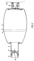
- FIG. 1 defines an elongated elastically compressible squeeze bag which is circular in cross section and which comprises an annular folding zone 2 of reduced wall thickness, said folding zone 2 being delimited by two annular and parallel grooves 3 on the outside of the squeeze bag 1.
- the resuscitator also comprises a strap 4 which is attached to the squeeze bag 1 at its ends.
- the squeeze bag comprises an opening at each end, the first opening having intake means 5 and the second opening having a transparent pipe 6 inserted therein.
- the intake means 5 consists of a circular disc 7 having along its periphery an annular groove which surrounds the edge of the opening, said edge being maintained in the groove 8 in a stretched state.
- the central part of the disc 7 has the shape of a valve seat with holes which holes are covered by a thin circular elastic valve flap 10 located on the interior side of the disc 7 and being attached to the valve seat by a centrally located pin 11.
- the exterior side of the disc 7 is integral with a housing 12 having two parallel side walls 13 with holes 14, said side walls forming valve seats for an intake valve mounted on the inside of the housing 12 and a relief valve mounted on the outside of the housing 12, respectively.
- the intake valve comprises in addition to the holes 14 a thin circular valve flap 15 which is attached to the valve seat by a pin 16.
- the relief valve comprises another thin circular valve flap 17 which is attached to the valve seat by means of a pin 18.
- the housing 12 is open at the end opposite to the disc 7 and in the embodiment shown in the drawing a holder 19 which overlaps the edges of a disc 20 attached to the mouth of a thin plastic bag 21 is attached to the free end of the housing 12.
- the holder 19 surrounds the housing 12 and the holder walls comprise holes 22 for intake and discharge of air and oxygen-containing gas, respectively.
- the housing 12 also comprises a pipe stub 23 for attachment of a tube for the supply of oxygen to the housing.
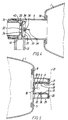
- the transparent pipe 6 comprises at one end an annular groove 30 surrounding the edge of the second opening in the squeeze bag 1, said edge being in a stretched state.
- a hollow member 31 having a central passage 32 surrounded by an annular bead 33 is screwed into the opposite end of the pipe 6.
- the bead 33 is in contact with a flexible elastic circular valve flap 34 having a central pin 35 which is inserted in a hole in a convex valve seat 36 with holes 37.
- the pin 35 is axially displaceable in the hole mentioned above and the movement in a direction away from the valve seat is restricted by a shoulder 38 on the pin 35.
- the pin 35 has a free end 39 and the movement of said end 39 can be observed through the wall of the transparent pipe 6.
- the branch pipe 40 is provided on the side of the transparent pipe 6 and the interior of the branch pipe 40 communicates through a hole 41 in the pipe wall with a space 42 which on one hand is delimited by the valve flap 34 and on the other hand by the hollow body 31.
- the resuscitator can be folded and placed in such a manner that it almost totally fills the interior of a box.
- the resuscitator shown can be operated in the following manner: After having placed a hand in such a manner that the strap 4 overlaps the hand the user is capable of subjecting the squeeze bag 1 to rhythmic compressions with one hand only.
- the compression of the squeeze bag 1 produces a gas flow from the squeeze bag 1 into the transparent pipe 6.
- the pressure increase thus produced causes the valve member 34 to be displaced relative to the valve seat 36 and to be pressed against the annular bead 33 thus permitting the gas to flow through the openings 37 in the valve seat 36 into the space 42 and from said space through the hole 41 and the pipe stub 40 towards a mask (not shown) connected with said pipe stub 40.
- the bag 1 When the compression of the squeeze bag 1 ceases, the bag 1 will tend to regain its original shape which tendency is supported by the tension generated by the strap 4.
- the pressure within said bag drops to a subatmospheric pressure and the valve body 34 will be pressed against the valve seat 36 so as to allow exhalation air to flow through the pipe stub 40, the hole 41, the space 42 and the central passage 32.
- the superatmospheric pressure exerted on the exterior side of the valve body 10 will allow intake of air from the housing 12 through the holes 9 in the disc 7.
- the pipe stub 23 When the pipe stub 23 is connected with a source of pressurized oxygen, the oxygen will flow constantly into the housing 12 and into the bag 21.
- the relief valve in the housing 12 When the bag 21 has been filled with oxygen and a slight superatmospheric pressure has been established therein, the relief valve in the housing 12 will open and excessive oxygen will flow out of the housing through the holes 14 and out through the holes 22 in the holder 19.
- oxygen will flow into said squeeze bag until there is no more oxygen present in the bag 21.
- the vacuum established in the housing 12 will open the intake valve of the housing 12 and air is caused to flow into the housing 12 through the holes 14 of the intake valve.
Description
- This invention relates to a disposable resuscitator comprising an elastically squeezable elongated bag having a first opening, a first one-way valve for intake of oxygen-containing air mounted in said first opening, a second opening which is in airtight connection with a valve housing comprising a pipe stub, which can be connected with a facial mask, and an outlet opening for exhalation air, the valve housing containing a two-way valve comprising a valve seat and a disc shaped valve body of an elastomeric material, said valve allowing oxygen-containing air to flow from the bag into the pipe stub when the pressure within the bag exceeds atmospheric pressure and exhalation air to flow from said pipe stub to the outlet opening when the pressure within the bag is lower than the pressure within the pipe stub.
- A re-usable resuscitator constructed essentially as described above is well known cf. i.a. DK -A-151.288. This known resuscitator comprises i.a. a squeeze bag comprising a self-expanding foldable insert.
- When such a known resuscitator has been used for the treatment of one patient and is to be used for the treatment of another patient it must be dismantled, cleaned and disinfected. Since this is a time-consuming operation and it further involves the risk that the resuscitator is re-assembled incorrectly there is a growing interest for limiting the use of such a resuscitator to one person only and discarding it after use.
- This has created a need for the development of simple and inexpensive but yet reliable resuscitators.
- It has been proposed to use squeeze bags without an insert and consisting of a plastics material and to reduce the freight costs the bags of some of the known apparatus have an annular folding zone of a reduced wall thickness so as to allow one end of the elongated bag to be folded into the remaining part of the squeeze bag. A resuscitator comprising such a foldable squeeze bag is disclosed in DE -A-1.616.421.
- The pipe stub of the known disposable resuscitators is located co-axially and parallel with the longitudinal axis of the squeeze bag and it is consequently necessary to provide an angled connecting piece between said pipe stub and the facial mask so as to allow the resuscitator to be operated by a single person by performing a rhythmic compression of the the bag with one hand and by maintaining the mask in contact with the patient's face in such a manner that it covers both the nose and the mouth with the other hand.
- DE -A-1.277.520 discloses a re-usable resuscitator having a valve housing located partly within the squeeze bag. The valve housing of the known resuscitator consists of two valve parts which are pressed together and which at their periphery form a flange fitting into a corresponding groove on the inner side of the bag opening. The two-way valve located within the valve housing described consists of a circular valve disc having a centrally located pin attached to a perforated valve seat forming part of one of the two valve parts. The interior surface of the other valve part comprises an annular bead provided around the outlet opening of the valve and effectively preventing oxygen-containing gas from leaking through the outlet opening of the valve. The valve housing of the known resuscitator also comprises a pipe stub extending parallel with the longitudinal axis of the squeeze bag.
- Other examples of resuscitator with similar types of two-way valve are described in US-A- 3 610 236 and in GB-A- 2 139 099.
- The resuscitator of the invention is characterized in that the valve housing has the shape of a pipe of a transparent material, that the disc-shaped elastomeric valve body comprises a centrally located guide pin, which is mounted axially displaceable in a hole in the valve seat, that a hollow member having a central passage forming said outlet opening is mounted in the free end of the transparent pipe, said central passage being surrounded by an annular bead mounted co-axially and in contact with the valve body, and that the pipe stub to be connected with a mask extends from the side of the transparent pipe and is connected with the zone located between the valve body and the hollow member located in the free end of the transparent pipe.
- Thus, the valve assembly comprises three components only, viz. the transparent pipe comprising a valve seat and a pipe stub, the valve body which is displaceable relative to the valve seat, and the hollow member having a central passage mounted in the free end of the transparent pipe.
- These three relatively simple components can easily be assembled and consequently the production costs and the costs of assembling are relatively small. Furthermore, the use of a transparent pipe and the central guide pin projecting from the valve body presents the advantage that the operator by visually following the movements of the pin can ascertain that the valve functions correctly.
- Thus, the pin moves away from the squeeze bag when oxygen containing gas flows from the squeeze bag to the patient and in the opposite direction when exhalation air flows from the patient and towards the outlet opening.
- The hollow member located in the free end of the transparent pipe is preferably provided with an external thread corresponding to a thread on the inner side of the pipe at its free end. Such threads facilitate the dismantling of said member if vomitus is to be quickly removed from the valve chamber.
- In order to facilitate the flow of exhalation air from the type stub located on the side of the transparent pipe to the outlet opening, the valve seat is preferably convex when seen from the free end of the transparent pipe. Such a shape permits the disc-shaped valve body to move away from the body inserted in the free end of the transparent pipe during the intake of breathing gas into the squeeze bag thus increasing the cross sectional area of the passage in which the exhalation air flows towards the outlet opening.
- In a preferred embodiment of the resuscitator of the invention the edge of the second opening in the squeeze bag is preferably placed in an annular groove provided on the exterior side of the transparent pipe in a stretched state so as to obtain an airtight connection between the transparent pipe and the squeeze bag and simultaneously allowing the transparent pipe to be rotated relatively to the squeeze bag.
- A particularly preferred embodiment of the resuscitator of the invention comprises a strap attached to the exterior side of the squeeze bag. This strap is preferably of such a length that an operator can introduce a hand into the zone between the exterior side of the squeeze bag and the inner side of the strap and thus is able to hold the resuscitator and simultaneously subjecting the squeeze bag to rhythmic compressions.
- When using a pear-shaped squeeze bag one end of the strap is preferably attached to the squeeze bag close to the end of the squeeze bag comprising the first opening and the opposite end of the strap is attached to the squeeze bag in a zone located halfway between the opposite end of the squeeze bag and the zone having the largest diameter.
- By attaching the strap to the squeeze bag in this manner the squeeze bag will rapidly expand, because the strap will generate a pull following the compression of the squeeze bag with a hand located under said strap.
- The one-way valve provided in the first opening in the squeeze bag is preferably a flap valve mounted on the interior side of the squeeze bag. The flap valve may comprise a circular elastic disc which is attached to a perforated valve seat by means of a centrally located pin.
- The one-way valve is preferably combined with a housing which extends outwardly from the one-way valve and is open at its free end and which is adapted to cooperate with a holder connected to a collapsible bag, two one-way valves being provided in the side walls of the housing, the first one-way valve allowing air to flow into the housing when a predetermined vacuum has been established in said housing and the second one-way valve allowing gas to flow out of the housing when a predetermined superatmospheric pressure has been established therein, and a pipe stub which can be connected with a source of oxygen-containing gas.
- The oxygen-containing gas which may be introduced into the housing through said pipe stub is preferably pure oxygen, e.g. supplied from a pressure vessel. When supplying oxygen directly from a pressure vessel to the inhalation air in the bag there is a risk of creating such a superatmospheric pressure in the air passages of a patient that it may endanger the patient. Such a risk is eliminated with the embodiment defined above. Thus, by introducing oxyen under pressure into the housing described through the pipe stub the oxygen will fill the collapsible bag and expand it. When the pressure within said bag exceeds the predetermined value the oxygen will start flowing out of the collapsible bag through the second one-way valve.
- Following compression of the squeeze bag the latter will expand and a vacuum is generated within said bag. This vacuum will spread into the housing and oxygen will be sucked into the squeeze bag from the collapsible bag. At the same time the first one-way valve will open thus permitting air to flow into the housing. By repeated use of the resuscitator a mixture of air and oxygen in a ratio determined by the oxygen flow and the compression volume and operational sequence of the squeeze bag will be supplied to the patient.
- The squeeze bag preferably comprises an annular folding zone located at such a distance from the second opening of the squeeze bag that the intermediate portion of the bag and the transparent pipe can be folded into that portion of the squeeze bag which is located between the folding zone and the first opening in the squeeze bag.
- The folding zone preferably is a zone of reduced thickness delimited by two annular grooves provided in the exterior side of the squeeze bag.
- The invention will now be described in further detail with reference to the drawing in which
- Fig. 1 shows a side view of a preferred embodiment of the resuscitator of the invention,
- Fig. 2 shows a longitudinal sectional view of the resuscitator shown in Fig. 1 perpendicularly to the plane of the paper,
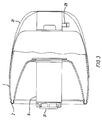
- Fig. 3 shows a side view partly in section of a resuscitator of the invention in a folded state,
- Fig. 4 shows an enlarged sectional view of the valve arrangement at the left end of the resuscitator shown in Fig. 2 and
- Fig. 5 shows an enlarged sectional view of the valve arrangement at the right end of the resuscitator shown in Fig. 2.
- In the drawing 1 defines an elongated elastically compressible squeeze bag which is circular in cross section and which comprises an
annular folding zone 2 of reduced wall thickness, saidfolding zone 2 being delimited by two annular andparallel grooves 3 on the outside of the squeeze bag 1. The resuscitator also comprises a strap 4 which is attached to the squeeze bag 1 at its ends. - The squeeze bag comprises an opening at each end, the first opening having intake means 5 and the second opening having a
transparent pipe 6 inserted therein. - The intake means 5 consists of a
circular disc 7 having along its periphery an annular groove which surrounds the edge of the opening, said edge being maintained in the groove 8 in a stretched state. The central part of thedisc 7 has the shape of a valve seat with holes which holes are covered by a thin circularelastic valve flap 10 located on the interior side of thedisc 7 and being attached to the valve seat by a centrally locatedpin 11. The exterior side of thedisc 7 is integral with ahousing 12 having twoparallel side walls 13 withholes 14, said side walls forming valve seats for an intake valve mounted on the inside of thehousing 12 and a relief valve mounted on the outside of thehousing 12, respectively. - The intake valve comprises in addition to the holes 14 a thin circular valve flap 15 which is attached to the valve seat by a
pin 16. Similarly, the relief valve comprises another thincircular valve flap 17 which is attached to the valve seat by means of a pin 18. Thehousing 12 is open at the end opposite to thedisc 7 and in the embodiment shown in the drawing aholder 19 which overlaps the edges of adisc 20 attached to the mouth of a thinplastic bag 21 is attached to the free end of thehousing 12. Theholder 19 surrounds thehousing 12 and the holder walls compriseholes 22 for intake and discharge of air and oxygen-containing gas, respectively. - The
housing 12 also comprises apipe stub 23 for attachment of a tube for the supply of oxygen to the housing. - The
transparent pipe 6 comprises at one end anannular groove 30 surrounding the edge of the second opening in the squeeze bag 1, said edge being in a stretched state. Ahollow member 31 having acentral passage 32 surrounded by anannular bead 33 is screwed into the opposite end of thepipe 6. When there is an atmospheric or superatmospheric pressure within the squeeze bag 1, thebead 33 is in contact with a flexible elasticcircular valve flap 34 having acentral pin 35 which is inserted in a hole in aconvex valve seat 36 withholes 37. Thepin 35 is axially displaceable in the hole mentioned above and the movement in a direction away from the valve seat is restricted by ashoulder 38 on thepin 35. Thepin 35 has afree end 39 and the movement of saidend 39 can be observed through the wall of thetransparent pipe 6. - The
branch pipe 40 is provided on the side of thetransparent pipe 6 and the interior of thebranch pipe 40 communicates through ahole 41 in the pipe wall with aspace 42 which on one hand is delimited by thevalve flap 34 and on the other hand by thehollow body 31. - As will appear from Fig. 3 the resuscitator can be folded and placed in such a manner that it almost totally fills the interior of a box.
- The resuscitator shown can be operated in the following manner:
After having placed a hand in such a manner that the strap 4 overlaps the hand the user is capable of subjecting the squeeze bag 1 to rhythmic compressions with one hand only. The compression of the squeeze bag 1 produces a gas flow from the squeeze bag 1 into thetransparent pipe 6. The pressure increase thus produced causes thevalve member 34 to be displaced relative to thevalve seat 36 and to be pressed against theannular bead 33 thus permitting the gas to flow through theopenings 37 in thevalve seat 36 into thespace 42 and from said space through thehole 41 and thepipe stub 40 towards a mask (not shown) connected with saidpipe stub 40. - When the compression of the squeeze bag 1 ceases, the bag 1 will tend to regain its original shape which tendency is supported by the tension generated by the strap 4. During the expansion of the squeeze bag 1 the pressure within said bag drops to a subatmospheric pressure and the
valve body 34 will be pressed against thevalve seat 36 so as to allow exhalation air to flow through thepipe stub 40, thehole 41, thespace 42 and thecentral passage 32. Simultaneously, the superatmospheric pressure exerted on the exterior side of thevalve body 10 will allow intake of air from thehousing 12 through theholes 9 in thedisc 7. - When the
pipe stub 23 is connected with a source of pressurized oxygen, the oxygen will flow constantly into thehousing 12 and into thebag 21. When thebag 21 has been filled with oxygen and a slight superatmospheric pressure has been established therein, the relief valve in thehousing 12 will open and excessive oxygen will flow out of the housing through theholes 14 and out through theholes 22 in theholder 19. Thus, during the expansion of the squeeze bag 1 oxygen will flow into said squeeze bag until there is no more oxygen present in thebag 21. At this stage the vacuum established in thehousing 12 will open the intake valve of thehousing 12 and air is caused to flow into thehousing 12 through theholes 14 of the intake valve. - By using the resuscitator illustrated inhalation air having a desired oxygen concentration of between 21 and 100% can be supplied to a patient.
Claims (8)
- A disposable resuscitator comprising an elastically squeezable elongated bag (1) having a first opening, a first one-way valve for intake of oxygen-containing air mounted in said first opening, a second opening which is in airtight connection with a valve housing comprising a pipe stub (40) which can be connected with a facial mask, and an outlet opening for exhalation air, the valve housing containing a two-way valve comprising a valve seat (36) and a disc-shaped valve body (34) of an elastomeric material, said valve allowing oxygen-containing air to flow from the bag into the pipe stub (40) when the pressure within the bag exceeds atmospheric pressure and exhalation air to flow from said pipe stub to the outlet opening when the pressure within the bag is lower than the pressure within the pipe stub, characterized in that the valve housing has the shape of a pipe (6) of a transparent material, in that the disc-shaped elastomeric valve body (34) comprises a centrally located guide pin (35) which is mounted axially displaceable in a hole in the valve seat, in that a hollow member (31) having a central passage (32) forming said outlet opening is mounted in the free end of the transparent pipe, said central passage being surrounded by an annular bead (33) mounted co-axially and in contact with the valve body, and in that the pipe stub to be connected with a mask extends from the side of the transparent pipe and is connected with the zone located between the valve body and the hollow member located in the free end of the transparent pipe (6).
- A resuscitator according to claim 1, characterized in that the hollow member (31) mounted in the free end of the transparent pipe (6) comprises an external thread corresponding to a thread on the inner side of the pipe at its free end.
- A resuscitator according to claim 1 or 2, characterized in that the valve seat is convex viewed in a direction away from the free end of the transparent pipe.
- A resuscitator according to any of the claims 1-3, characterized in that the edge of the second opening in the squeeze bag is located in an annular groove (30) on the outer side of the transparent pipe in a stretched state.
- A resuscitator according to any of the preceding claims, characterized in that a strap (4) is attached to the outer side of the squeeze bag.
- A resuscitator according to claim 5 comprising a pear-shaped squeeze bag, characterized in that one end of the strap is attached to the bag close to the end comprising the first opening, and that the opposite end of the strap is attached to the squeeze bag halfway between the opposite end of the squeeze bag and the zone having the largest diameter.
- A resuscitator according to any of the preceding claims, characterized in that the first one-way valve located in the first opening of the squeeze bag comprises a housing extending outwardly from the valve and being open at its free end, said free end carrying a holder with a compressible bag attached thereto, the side walls of the housing comprising two holes, a second and a third one-way valves mounted in each hole, said second one-way valve permitting intake of air when the predetermined vacuum has been established in the housing and said third one-way valve permitting discharge of gas from the housing when the pressure therein exceeds a predetermined value, said housing further comprising a pipe stub for supplying oxygen-containing gas to the housing.
- A resuscitator according to any of the preceding claims, characterized in that the squeeze bag (1) comprises an annular folding zone (2) which is located at such a distance from the second opening in the squeeze bag that the part of the squeeze bag which is located between the transparent pipe and the folding zone as well as the transparent pipe can be folded into the remaining part of the squeeze bag.
Applications Claiming Priority (2)
| Application Number | Priority Date | Filing Date | Title |
|---|---|---|---|
| DK619688A DK160130C (en) | 1988-11-04 | 1988-11-04 | SINGLE USE RESUSCITATOR |
| DK6196/88 | 1988-11-04 |
Publications (3)
| Publication Number | Publication Date |
|---|---|
| EP0367285A2 EP0367285A2 (en) | 1990-05-09 |
| EP0367285A3 EP0367285A3 (en) | 1990-10-24 |
| EP0367285B1 true EP0367285B1 (en) | 1993-03-17 |
Family
ID=8147970
Family Applications (1)
| Application Number | Title | Priority Date | Filing Date |
|---|---|---|---|
| EP89120394A Expired - Lifetime EP0367285B1 (en) | 1988-11-04 | 1989-11-03 | Disposable resuscitator |
Country Status (6)
| Country | Link |
|---|---|
| US (1) | US5163424A (en) |
| EP (1) | EP0367285B1 (en) |
| JP (1) | JP2922546B2 (en) |
| AU (1) | AU623696B2 (en) |
| DE (1) | DE68905437T2 (en) |
| DK (1) | DK160130C (en) |
Cited By (8)
| Publication number | Priority date | Publication date | Assignee | Title |
|---|---|---|---|---|
| US6938618B2 (en) | 2003-09-11 | 2005-09-06 | Advanced Circulatory Systems, Inc. | Bag-valve resuscitation for treatment of hypotention, head trauma, and cardiac arrest |
| US7082945B2 (en) | 2003-04-28 | 2006-08-01 | Advanced Circulatory Systems, Inc. | Ventilator and methods for treating head trauma |
| US7174891B2 (en) | 1993-11-09 | 2007-02-13 | Advanced Circulatory Systems, Inc. | CPR mask with compression timing metronome and methods |
| US7766011B2 (en) | 2003-04-28 | 2010-08-03 | Advanced Circulatory Systems, Inc. | Positive pressure systems and methods for increasing blood pressure and circulation |
| US7836881B2 (en) | 2003-04-28 | 2010-11-23 | Advanced Circulatory Systems, Inc. | Ventilator and methods for treating head trauma and low blood circulation |
| US8011367B2 (en) | 2003-09-11 | 2011-09-06 | Advanced Circulatory Systems, Inc. | CPR devices and methods utilizing a continuous supply of respiratory gases |
| US8151790B2 (en) | 2007-04-19 | 2012-04-10 | Advanced Circulatory Systems, Inc. | Volume exchanger valve system and method to increase circulation during CPR |
| US9352111B2 (en) | 2007-04-19 | 2016-05-31 | Advanced Circulatory Systems, Inc. | Systems and methods to increase survival with favorable neurological function after cardiac arrest |
Families Citing this family (68)
| Publication number | Priority date | Publication date | Assignee | Title |
|---|---|---|---|---|
| US5360009A (en) * | 1992-08-14 | 1994-11-01 | Qosina Corp. | Spirometer mouthpiece |
| US5427091A (en) * | 1993-02-16 | 1995-06-27 | Phillips; Paul V. | Pneumatic compressor for bag-valve-mask resuscitators |
| US5408995A (en) * | 1993-04-16 | 1995-04-25 | Figgie International Inc. | Continuous flow passenger oxygen dispensing unit |
| US5357951A (en) * | 1993-06-02 | 1994-10-25 | Mercury Enterprises, Inc | Cardiac pulmonary resuscitator apparatus valve with integral air sampling port |
| US5692498A (en) * | 1993-11-09 | 1997-12-02 | Cprx, Inc. | CPR device having valve for increasing the duration and magnitude of negative intrathoracic pressures |
| US6425393B1 (en) | 1993-11-09 | 2002-07-30 | Cprx Llc | Automatic variable positive expiratory pressure valve and methods |
| US5551420A (en) * | 1993-11-09 | 1996-09-03 | Cprx, Inc. | CPR device and method with structure for increasing the duration and magnitude of negative intrathoracic pressures |
| US7195013B2 (en) | 1993-11-09 | 2007-03-27 | Advanced Circulatory Systems, Inc. | Systems and methods for modulating autonomic function |
| US6604523B2 (en) | 1993-11-09 | 2003-08-12 | Cprx Llc | Apparatus and methods for enhancing cardiopulmonary blood flow and ventilation |
| US7195012B2 (en) * | 2003-04-28 | 2007-03-27 | Advanced Circulatory Systems, Inc. | Systems and methods for reducing intracranial pressure |
| US6062219A (en) | 1993-11-09 | 2000-05-16 | Cprx Llc | Apparatus and methods for assisting cardiopulmonary resuscitation |
| DE4439474C1 (en) * | 1994-11-08 | 1996-03-14 | Heraeus Med Gmbh | Breathing gas container with flexible bag having opening |
| US5540221A (en) * | 1994-11-17 | 1996-07-30 | Respironics, Inc. | Resuscitator |
| CN1089012C (en) * | 1995-03-10 | 2002-08-14 | Cprx公司 | CPR device having structure for increasing duration and magnitude of negative intra-thoracic pressure |
| DE19517857C1 (en) * | 1995-05-16 | 1996-05-09 | Ruesch Willy Ag | Breathing bag for sick or injured people |
| AUPN417395A0 (en) * | 1995-07-14 | 1995-08-10 | Techbase Pty. Ltd. | An improved spacer |
| AUPN538495A0 (en) | 1995-09-12 | 1995-10-05 | Esnouf, Philip Stuart | Disposable oxygenating device |
| AU721704B2 (en) * | 1995-09-12 | 2000-07-13 | Teleflex Life Sciences | Disposable oxygenating device |
| US5692494A (en) * | 1996-09-26 | 1997-12-02 | Ohmeda Inc. | Adjustable breathing circuit bag arm |
| US5730122A (en) * | 1996-11-12 | 1998-03-24 | Cprx, Inc. | Heart failure mask and methods for increasing negative intrathoracic pressures |
| US5803074A (en) * | 1996-11-25 | 1998-09-08 | Smiths Industries Medical Systems, Inc. | Valve for resuscitator apparatus |
| US6234985B1 (en) | 1998-06-11 | 2001-05-22 | Cprx Llc | Device and method for performing cardiopulmonary resuscitation |
| US6312399B1 (en) | 1998-06-11 | 2001-11-06 | Cprx, Llc | Stimulatory device and methods to enhance venous blood return during cardiopulmonary resuscitation |
| US6463327B1 (en) | 1998-06-11 | 2002-10-08 | Cprx Llc | Stimulatory device and methods to electrically stimulate the phrenic nerve |
| US6155257A (en) * | 1998-10-07 | 2000-12-05 | Cprx Llc | Cardiopulmonary resuscitation ventilator and methods |
| US6253767B1 (en) | 1998-12-10 | 2001-07-03 | Robert F. Mantz | Gas concentrator |
| AUPP794598A0 (en) * | 1998-12-24 | 1999-01-28 | Resmed Limited | An anti-asphyxia valve |
| US7063086B2 (en) * | 1999-09-23 | 2006-06-20 | Fisher & Paykel Healthcare Limited | Breathing assistance apparatus |
| AU778777B2 (en) * | 1999-09-23 | 2004-12-23 | Fisher & Paykel Healthcare Limited | Breathing assistance apparatus |
| US7121278B2 (en) | 2001-01-23 | 2006-10-17 | Michael David Maguire | Method and apparatus for manual delivery of volume and pressure-control artificial ventilation |
| DE10106009C1 (en) * | 2001-02-10 | 2002-04-25 | Draeger Medical Ag | Respiration bag which can be used with both oxygen and air, has annular folds enabling stable configuration in either of two different volumes |
| US9132253B2 (en) * | 2001-02-23 | 2015-09-15 | Lawrence A. Lynn | Asthma resuscitation system and method |
| US6910084B2 (en) * | 2001-04-30 | 2005-06-21 | Medtronic, Inc | Method and system for transferring and storing data in a medical device with limited storage and memory |
| US6776156B2 (en) | 2001-09-28 | 2004-08-17 | Advanced Circulatory Systems, Inc. | Systems and methods to facilitate the delivery of drugs |
| NO318093B1 (en) | 2002-07-15 | 2005-01-31 | Laerdal Medical As | Reusable intake valve for resisator bag. |
| US6863656B2 (en) | 2002-09-20 | 2005-03-08 | Advanced Circulatory Systems, Inc. | Stress test devices and methods |
| US7682312B2 (en) | 2002-09-20 | 2010-03-23 | Advanced Circulatory Systems, Inc. | System for sensing, diagnosing and treating physiological conditions and methods |
| US7044128B2 (en) | 2003-04-08 | 2006-05-16 | Advanced Circulatory Systems, Inc. | CPR demonstration device and methods |
| EP3064242A1 (en) | 2003-04-28 | 2016-09-07 | Advanced Circulatory Systems Inc. | Ventilator and methods for treating head trauma and low blood circulation |
| US7051596B1 (en) | 2003-10-03 | 2006-05-30 | Ventlab Corporation | Manual resuscitators with integral manometer |
| US7806118B2 (en) * | 2004-04-06 | 2010-10-05 | Thompson Darrell K | Cardiopulmonary resuscitation device |
| US8281788B2 (en) * | 2004-04-06 | 2012-10-09 | Thompson Darrel K | Cardiopulmonary resuscitation device |
| US7032596B2 (en) * | 2004-04-06 | 2006-04-25 | Thompson Darrell K | Cardiopulmonary resuscitation device and method |
| KR100656707B1 (en) | 2004-12-09 | 2006-12-12 | 코리아세이프티주식회사 | an oxygen supply with artificial respirator |
| WO2006074511A1 (en) * | 2005-01-12 | 2006-07-20 | Infamed Limited | A one-way valve |
| GB0509371D0 (en) * | 2005-05-07 | 2005-06-15 | Smiths Group Plc | Resuscitators |
| US7360538B2 (en) * | 2005-07-18 | 2008-04-22 | Stephen Flynn | Oxygen therapy face mask |
| US20070039619A1 (en) * | 2005-08-22 | 2007-02-22 | Kohnke Ole B | Manual resuscitator with oxygen tubing reservoir |
| US8266857B2 (en) * | 2006-09-27 | 2012-09-18 | David Barlow R | Interlocking floor system with barbs for retaining covering |
| US7930865B2 (en) * | 2006-09-27 | 2011-04-26 | Barlow David R | Method of installing an interlocking floor system |
| US8327848B2 (en) | 2006-09-28 | 2012-12-11 | Ric Investments, Llc | Pressure reducing valve |
| US20080257351A1 (en) * | 2007-04-19 | 2008-10-23 | David Gitschlag | Resuscitation device |
| US8365731B2 (en) * | 2007-07-31 | 2013-02-05 | Ric Investments, Llc | Pressure reducing valve with flexible cuff |
| WO2009047763A1 (en) * | 2007-10-09 | 2009-04-16 | Micro Bvm Ltd. | Respiration bag |
| US9724266B2 (en) | 2010-02-12 | 2017-08-08 | Zoll Medical Corporation | Enhanced guided active compression decompression cardiopulmonary resuscitation systems and methods |
| US9238115B2 (en) | 2011-12-19 | 2016-01-19 | ResQSystems, Inc. | Systems and methods for therapeutic intrathoracic pressure regulation |
| US9811634B2 (en) | 2013-04-25 | 2017-11-07 | Zoll Medical Corporation | Systems and methods to predict the chances of neurologically intact survival while performing CPR |
| US20140358047A1 (en) | 2013-05-30 | 2014-12-04 | ResQSystems, Inc. | End-tidal carbon dioxide and amplitude spectral area as non-invasive markers of coronary perfusion pressure and arterial pressure |
| US10265495B2 (en) | 2013-11-22 | 2019-04-23 | Zoll Medical Corporation | Pressure actuated valve systems and methods |
| US10016570B2 (en) | 2014-10-09 | 2018-07-10 | Emendare Innovations, Llc | Bag/valve/mask resuscitator stabilizer arm and method of use |
| WO2017059292A1 (en) * | 2015-10-01 | 2017-04-06 | Fukunaga Atsuo F | Systems and methods for providing resuscitation, assisted ventilation and anesthesia |
| CN106075681A (en) * | 2016-06-04 | 2016-11-09 | 吴洪磊 | A kind of simply respirator |
| US10738484B2 (en) | 2016-07-11 | 2020-08-11 | 308, Llc | Shock absorbing interlocking floor system |
| US9631375B1 (en) | 2016-07-11 | 2017-04-25 | 308, Llc | Shock absorbing interlocking floor system |
| WO2019195579A1 (en) | 2018-04-06 | 2019-10-10 | Vms Medical Products, Inc. | Mouth shield device for treatment of dry mouth, teeth grinding, snoring, and sleep apnea and methods of use thereof |
| JP2023520885A (en) * | 2020-03-30 | 2023-05-22 | エアミッド クリティカル ケア プロダクツ インコーポレイテッド | Apparatus and method for convertible volume and pressure controlled lung protective ventilation |
| US20230372649A1 (en) | 2020-10-15 | 2023-11-23 | Ambu A/S | Resuscitator |
| US11420010B1 (en) | 2021-10-01 | 2022-08-23 | Compact Medical Inc. | Bag and valve for advanced respiratory support |
Family Cites Families (16)
| Publication number | Priority date | Publication date | Assignee | Title |
|---|---|---|---|---|
| CH293574A (en) * | 1951-08-28 | 1953-09-30 | Laubscher & Co Ag | Hand operated resuscitation apparatus. |
| US3083707A (en) * | 1956-02-13 | 1963-04-02 | Henry W Seeler | Device for treatment of pulmonary diseases |
| US3046978A (en) * | 1960-06-22 | 1962-07-31 | Lawrence N Lea | Manually operated resuscitator |
| BE623708A (en) * | 1961-10-24 | |||
| US3262446A (en) * | 1963-11-18 | 1966-07-26 | Air Shields | Resuscitator |
| US3473529A (en) * | 1966-05-23 | 1969-10-21 | Air Reduction | Squeeze-bag resuscitator |
| US3610236A (en) * | 1966-11-22 | 1971-10-05 | Globe Safety Products Inc | Resuscitator device |
| US3827440A (en) * | 1973-01-18 | 1974-08-06 | A Birch | Check-valve for tracheotomy tubes |
| US4088131A (en) * | 1974-04-11 | 1978-05-09 | Jim E. Rand Training Systems, Inc. | Breathing assistance device |
| SE387052B (en) * | 1974-09-20 | 1976-08-30 | Testa Lab A S | DEVICE FOR SUCTION AND FORCED EXHAUST OF A MIXTURE OF SEVERAL TREATMENT GASES |
| US4077404A (en) * | 1975-09-17 | 1978-03-07 | H. B. W. Medical Instruments Manufacturing Company, Inc. | Breathing equipment such as resuscitators |
| US4374521A (en) * | 1980-09-12 | 1983-02-22 | Puritan-Bennett Corporation | Squeeze bag type resuscitator apparatus |
| US4501271A (en) * | 1981-10-13 | 1985-02-26 | John William Spear | Resuscitator |
| DE3416350A1 (en) * | 1983-05-04 | 1984-11-08 | Inspiron Corp., Rancho Cucamonga, Calif. | VENTILATOR |
| US4774941A (en) * | 1983-05-04 | 1988-10-04 | Intertech Resources Inc. | Resuscitator bag |
| EP0139363A1 (en) * | 1983-08-02 | 1985-05-02 | O-Two Systems International Inc. | Breathing apparatus |
-
1988
- 1988-11-04 DK DK619688A patent/DK160130C/en not_active IP Right Cessation
-
1989
- 1989-11-02 JP JP1287290A patent/JP2922546B2/en not_active Expired - Lifetime
- 1989-11-02 AU AU43987/89A patent/AU623696B2/en not_active Ceased
- 1989-11-03 EP EP89120394A patent/EP0367285B1/en not_active Expired - Lifetime
- 1989-11-03 DE DE8989120394T patent/DE68905437T2/en not_active Expired - Lifetime
-
1992
- 1992-01-27 US US07/825,286 patent/US5163424A/en not_active Expired - Lifetime
Cited By (10)
| Publication number | Priority date | Publication date | Assignee | Title |
|---|---|---|---|---|
| US7174891B2 (en) | 1993-11-09 | 2007-02-13 | Advanced Circulatory Systems, Inc. | CPR mask with compression timing metronome and methods |
| US7082945B2 (en) | 2003-04-28 | 2006-08-01 | Advanced Circulatory Systems, Inc. | Ventilator and methods for treating head trauma |
| US7766011B2 (en) | 2003-04-28 | 2010-08-03 | Advanced Circulatory Systems, Inc. | Positive pressure systems and methods for increasing blood pressure and circulation |
| US7836881B2 (en) | 2003-04-28 | 2010-11-23 | Advanced Circulatory Systems, Inc. | Ventilator and methods for treating head trauma and low blood circulation |
| US8408204B2 (en) | 2003-04-28 | 2013-04-02 | Advanced Circulatory Systems, Inc. | Positive pressure systems and methods for increasing blood pressure and circulation |
| US6938618B2 (en) | 2003-09-11 | 2005-09-06 | Advanced Circulatory Systems, Inc. | Bag-valve resuscitation for treatment of hypotention, head trauma, and cardiac arrest |
| US7275542B2 (en) | 2003-09-11 | 2007-10-02 | Advanced Circulatory Systems, Inc. | Bag-valve resuscitation for treatment of hypotension, head trauma, and cardiac arrest |
| US8011367B2 (en) | 2003-09-11 | 2011-09-06 | Advanced Circulatory Systems, Inc. | CPR devices and methods utilizing a continuous supply of respiratory gases |
| US8151790B2 (en) | 2007-04-19 | 2012-04-10 | Advanced Circulatory Systems, Inc. | Volume exchanger valve system and method to increase circulation during CPR |
| US9352111B2 (en) | 2007-04-19 | 2016-05-31 | Advanced Circulatory Systems, Inc. | Systems and methods to increase survival with favorable neurological function after cardiac arrest |
Also Published As
| Publication number | Publication date |
|---|---|
| EP0367285A3 (en) | 1990-10-24 |
| DE68905437D1 (en) | 1993-04-22 |
| DK160130B (en) | 1991-02-04 |
| US5163424A (en) | 1992-11-17 |
| JPH02168965A (en) | 1990-06-29 |
| JP2922546B2 (en) | 1999-07-26 |
| DK619688A (en) | 1990-05-05 |
| DE68905437T2 (en) | 1993-09-23 |
| DK160130C (en) | 1991-07-15 |
| DK619688D0 (en) | 1988-11-04 |
| EP0367285A2 (en) | 1990-05-09 |
| AU623696B2 (en) | 1992-05-21 |
| AU4398789A (en) | 1990-05-10 |
Similar Documents
| Publication | Publication Date | Title |
|---|---|---|
| EP0367285B1 (en) | Disposable resuscitator | |
| US4774941A (en) | Resuscitator bag | |
| US5558371A (en) | Resuscitator | |
| US5007420A (en) | Ventilator having an oscillatory inspiratory phase and method | |
| US4592349A (en) | Ventilator having an oscillatory inspiratory phase and method | |
| US4121580A (en) | Squeeze bag resuscitator with air-oxygen proportionating control | |
| US5109839A (en) | Inhalation apparatus | |
| US5862802A (en) | Ventilator having an oscillatory inspiratory phase and method | |
| US5116088A (en) | Ventilator having an oscillatory inspiratory phase and method | |
| EP1023099B1 (en) | Pulmonary pressure modulator | |
| US4051847A (en) | Anesthesia rebreathing apparatus | |
| GB2139099A (en) | Resuscitator | |
| US5540221A (en) | Resuscitator | |
| US5419317A (en) | Inhalation apparatus | |
| US3826255A (en) | Intermittent positive pressure breathing manifold | |
| US5546934A (en) | Resuscitator | |
| US4276876A (en) | Respirator apparatus | |
| CA2231813A1 (en) | Disposable oxygenating device | |
| EP2777734A2 (en) | Medical breathing apparatus | |
| EP3646912B1 (en) | Percussive ventilation breathing head | |
| US5803074A (en) | Valve for resuscitator apparatus | |
| AU2003207042B2 (en) | Intake Valve | |
| EP0097060A2 (en) | Improvements in or relating to respiratory apparatus | |
| US5285775A (en) | Surgical breathing bag having hour-glass shape and non-slip surface | |
| US20020108612A1 (en) | Respiration bag |
Legal Events
| Date | Code | Title | Description |
|---|---|---|---|
| PUAI | Public reference made under article 153(3) epc to a published international application that has entered the european phase |
Free format text: ORIGINAL CODE: 0009012 |
|
| AK | Designated contracting states |
Kind code of ref document: A2 Designated state(s): DE FR GB IT SE |
|
| PUAL | Search report despatched |
Free format text: ORIGINAL CODE: 0009013 |
|
| AK | Designated contracting states |
Kind code of ref document: A3 Designated state(s): DE FR GB IT SE |
|
| 17P | Request for examination filed |
Effective date: 19901221 |
|
| 17Q | First examination report despatched |
Effective date: 19920519 |
|
| GRAA | (expected) grant |
Free format text: ORIGINAL CODE: 0009210 |
|
| AK | Designated contracting states |
Kind code of ref document: B1 Designated state(s): DE FR GB IT SE |
|
| REF | Corresponds to: |
Ref document number: 68905437 Country of ref document: DE Date of ref document: 19930422 |
|
| ET | Fr: translation filed | ||
| ITF | It: translation for a ep patent filed |
Owner name: JACOBACCI CASETTA & PERANI S.P.A. |
|
| PLBE | No opposition filed within time limit |
Free format text: ORIGINAL CODE: 0009261 |
|
| STAA | Information on the status of an ep patent application or granted ep patent |
Free format text: STATUS: NO OPPOSITION FILED WITHIN TIME LIMIT |
|
| 26N | No opposition filed | ||
| EAL | Se: european patent in force in sweden |
Ref document number: 89120394.5 |
|
| PGFP | Annual fee paid to national office [announced via postgrant information from national office to epo] |
Ref country code: SE Payment date: 20001120 Year of fee payment: 12 |
|
| PGFP | Annual fee paid to national office [announced via postgrant information from national office to epo] |
Ref country code: FR Payment date: 20001130 Year of fee payment: 12 |
|
| PG25 | Lapsed in a contracting state [announced via postgrant information from national office to epo] |
Ref country code: SE Free format text: LAPSE BECAUSE OF NON-PAYMENT OF DUE FEES Effective date: 20011104 |
|
| REG | Reference to a national code |
Ref country code: GB Ref legal event code: IF02 |
|
| EUG | Se: european patent has lapsed |
Ref document number: 89120394.5 |
|
| PG25 | Lapsed in a contracting state [announced via postgrant information from national office to epo] |
Ref country code: FR Free format text: LAPSE BECAUSE OF NON-PAYMENT OF DUE FEES Effective date: 20020730 |
|
| REG | Reference to a national code |
Ref country code: FR Ref legal event code: ST |
|
| REG | Reference to a national code |
Ref country code: FR Ref legal event code: ST |
|
| PGFP | Annual fee paid to national office [announced via postgrant information from national office to epo] |
Ref country code: DE Payment date: 20081103 Year of fee payment: 20 |
|
| PGFP | Annual fee paid to national office [announced via postgrant information from national office to epo] |
Ref country code: IT Payment date: 20081126 Year of fee payment: 20 |
|
| PGFP | Annual fee paid to national office [announced via postgrant information from national office to epo] |
Ref country code: GB Payment date: 20081029 Year of fee payment: 20 |
|
| REG | Reference to a national code |
Ref country code: GB Ref legal event code: PE20 Expiry date: 20091102 |
|
| PG25 | Lapsed in a contracting state [announced via postgrant information from national office to epo] |
Ref country code: GB Free format text: LAPSE BECAUSE OF EXPIRATION OF PROTECTION Effective date: 20091102 |