EP0367752A1 - Device for determining the concentration of at least one substance in living tissue - Google Patents
Device for determining the concentration of at least one substance in living tissue Download PDFInfo
- Publication number
- EP0367752A1 EP0367752A1 EP89890261A EP89890261A EP0367752A1 EP 0367752 A1 EP0367752 A1 EP 0367752A1 EP 89890261 A EP89890261 A EP 89890261A EP 89890261 A EP89890261 A EP 89890261A EP 0367752 A1 EP0367752 A1 EP 0367752A1
- Authority
- EP
- European Patent Office
- Prior art keywords
- pump
- suction
- container
- pumping
- perfusion
- Prior art date
- Legal status (The legal status is an assumption and is not a legal conclusion. Google has not performed a legal analysis and makes no representation as to the accuracy of the status listed.)
- Granted
Links
Images

Classifications
-
- A—HUMAN NECESSITIES
- A61—MEDICAL OR VETERINARY SCIENCE; HYGIENE
- A61M—DEVICES FOR INTRODUCING MEDIA INTO, OR ONTO, THE BODY; DEVICES FOR TRANSDUCING BODY MEDIA OR FOR TAKING MEDIA FROM THE BODY; DEVICES FOR PRODUCING OR ENDING SLEEP OR STUPOR
- A61M5/00—Devices for bringing media into the body in a subcutaneous, intra-vascular or intramuscular way; Accessories therefor, e.g. filling or cleaning devices, arm-rests
- A61M5/178—Syringes
- A61M5/31—Details
- A61M5/32—Needles; Details of needles pertaining to their connection with syringe or hub; Accessories for bringing the needle into, or holding the needle on, the body; Devices for protection of needles
- A61M5/329—Needles; Details of needles pertaining to their connection with syringe or hub; Accessories for bringing the needle into, or holding the needle on, the body; Devices for protection of needles characterised by features of the needle shaft
-
- A—HUMAN NECESSITIES
- A61—MEDICAL OR VETERINARY SCIENCE; HYGIENE
- A61B—DIAGNOSIS; SURGERY; IDENTIFICATION
- A61B5/00—Measuring for diagnostic purposes; Identification of persons
- A61B5/145—Measuring characteristics of blood in vivo, e.g. gas concentration, pH value; Measuring characteristics of body fluids or tissues, e.g. interstitial fluid, cerebral tissue
- A61B5/14532—Measuring characteristics of blood in vivo, e.g. gas concentration, pH value; Measuring characteristics of body fluids or tissues, e.g. interstitial fluid, cerebral tissue for measuring glucose, e.g. by tissue impedance measurement
-
- A—HUMAN NECESSITIES
- A61—MEDICAL OR VETERINARY SCIENCE; HYGIENE
- A61M—DEVICES FOR INTRODUCING MEDIA INTO, OR ONTO, THE BODY; DEVICES FOR TRANSDUCING BODY MEDIA OR FOR TAKING MEDIA FROM THE BODY; DEVICES FOR PRODUCING OR ENDING SLEEP OR STUPOR
- A61M5/00—Devices for bringing media into the body in a subcutaneous, intra-vascular or intramuscular way; Accessories therefor, e.g. filling or cleaning devices, arm-rests
- A61M5/178—Syringes
- A61M5/31—Details
- A61M5/32—Needles; Details of needles pertaining to their connection with syringe or hub; Accessories for bringing the needle into, or holding the needle on, the body; Devices for protection of needles
- A61M5/329—Needles; Details of needles pertaining to their connection with syringe or hub; Accessories for bringing the needle into, or holding the needle on, the body; Devices for protection of needles characterised by features of the needle shaft
- A61M5/3291—Shafts with additional lateral openings
Definitions
- the invention relates to a device for determining the concentration of at least one substance present in organic tissue, preferably the glucose concentration, with a subcutaneous needle that can be inserted into the tissue, a pump and suction device being provided for supplying a perfusion liquid and for removing it after its partial equilibration with the tissue is and the degree of interaction with the tissue can be determined by endogenous or exogenous marker sizes of the perfusion liquid, and with an analysis device with measuring devices for detecting the concentration of the substance to be determined and the marker sizes.
- a particularly sought after application is the continuous determination of the glucose concentration in the organism.
- Methods and devices for dialysis are known from US Pat. Nos. 4,221,567, 4,253,456 and 4,516,580, for example, in which at least one cannula or catheter is introduced into the blood stream.
- a complete equilibration of a measuring liquid with the blood is achieved via dialysis membranes, which is then analyzed for the substance of interest, for example glucose.
- the membranes loaded on one side by the measuring liquid and on the other side by the body fluid, for example blood which are sufficient for adequate equilibration must be large, however, there will soon be contamination or blockage of the membranes by body substances, so that the exchange of the substances of interest is quickly hindered.
- glucose pen For this purpose, a device of the type mentioned at the outset has become known from WO88 / 05643, which avoids the disadvantages mentioned above.
- An embodiment referred to as a “glucose pen” here has an approximately pen-shaped housing which has a subcutaneous needle at one end. Inside the housing there is a piston pump with a reservoir for the perfusion liquid, from which the piston can be used to pump the perfusate out of the piston chamber as well as suck it into the collection container that is released behind the piston.
- the piston can be manually moved via a possibly necessary gear and perfusion liquid can be brought to the openings in the wall by means of a first lumen in the subcutaneous needle and at the same time collected by the suction in the collecting container by a second, for example concentrically arranged lumen.
- An analyzer with a measuring capillary for the substance to be determined and the marker size is attached to the draining line as close as possible to the subcutaneous needle. Liquid can therefore be pumped through the subcutaneous needle for a short time, for example in the order of magnitude of approximately 1 minute or less, and collected again after its partial equilibration.
- the true concentration of the substance of interest for example blood sugar
- an optical display or an acoustic display which is calculated by the analysis unit from the concentration of the marker substance and the substance of interest.
- a constant perfusion rate can be achieved via the lever device, the lever of which is repeatedly operated during the perfusion period.
- the lever can be brought into its starting position again and again, for example by means of a spring or another energy store.
- the perfusion rate during the collection period is in the order of 1 to 10 ⁇ l / min.
- the only disadvantage is the complicated structure of this "glucose pen", the production of the multi-lumen subcutaneous needle in particular being technically difficult and cost-intensive.
- the object of the invention is to propose a device which, based on the prior art mentioned, can be produced more easily and cost-effectively, the main advantages of the generic device being retained.
- a single-lumen subcutaneous needle is provided, the lumen of which can be connected to the analysis device, the analysis device is connected on the output side to the pump and suction device, and the flow direction of the perfusion liquid in the lumen of the subcutaneous needle when changing from the pump is reversible for suction operation.
- the perfusate After partial equilibration of the perfusate with the tissue attached to the subcutaneous needle, the perfusate is sucked out of the needle and brought back into contact with the sensors of the analysis device, the substance to be determined and the marker size, e.g. the electrical conductivity, measured and from these values the actual concentration, e.g. the glucose concentration is calculated.
- the perfusion liquid in the example given should be essentially free of ions and glucose.
- Another advantage of the device according to the invention is that single-lumen subcutaneous needles can be made correspondingly thinner, so that the patient, for example, in the Tissue sugar analysis to be carried out several times a day has to bear less pain.
- the subcutaneous needle has a slit-shaped extension along the needle axis, or that the subcutaneous needle has at least one further opening in the wall area in addition to the front opening.
- multiple openings are made in multiple rows on the circumference of the needle.
- the analysis device has a conical plug connection on both sides, with which the analysis device is connected on one side to the subcutaneous needle and on the other side via a connecting line to the pump and suction device, the Plug connection via detachable contacts creates an electrical connection between the evaluation unit and the analysis device.
- the plug connections guarantee easy changing of the needle or the analysis device.
- a further development of the invention provides that a multi-way valve is arranged between the pump and suction device and the analysis device, via which the pump and suction device in a first position of the valve with the subcutaneous needle and in a second position with an opening for supplying outside air. The air bubble that can be sucked in via the valve then separates the two liquid columns.
- the pump and suction device has a piston pump, the piston chamber of which is designed as a perfusion container, and that an energy store charged during the pump stroke is provided for the suction stroke.
- the piston pump which can preferably be operated by hand, the patient only has to press a lever device after the piercing and release it later, as a result of which the analysis process runs automatically.
- a spring serves as an energy store.
- An advantageous development of the invention is that a mechanism is provided in the pump drive, which ensures small pumping and suctioning movements of the piston of the piston pump between pump and suction stroke, in the equilibration phase of the perfusion liquid.
- the pump movements in the equilibration phase are thus carried out by a mechanism to which the required energy can also be supplied via the lever device which triggers the pump stroke.
- a perfusion container and at least one container for a medicament to be administered is provided, and that the pump and suction device in a third position of the reusable valve with the perfusion container, and in at least one further position with each communicates with a container for a medicament.
- a container for a fast-acting insulin a container for long-acting insulin and a container for a hormone that increases blood sugar can be provided.
- a further development according to the invention provides that the perfusion container and the container for medication are easily deformable plastic bags and form an interchangeable unit together with the reusable valve and the corresponding connecting lines.
- the required amount of medication which can be identified on the basis of the measured value of the concentration of the substances to be determined, can then be applied via the already inserted subcutaneous needle without further puncturing the patient. After the perfusion container or the container for the medication has been emptied, they can be replaced together with the reusable valve and the necessary connecting lines as a unit for a new one.
- the interchangeable unit via a pressure-tight connection preferably via a puncture septum or O-ring seal is connected to the pumping and suction device, the interior of the line section of the connecting line lying between the reusable valve and the pressure-tight connection corresponding to the volume of at least one suction stroke.
- the line section located between the septum or O-ring sealing point and the reusable valve can completely absorb a suction stroke due to its internal volume, as a result of which the subsequent pumping and suctioning device is not contaminated.
- the required volume can either be realized by a rolled-up capillary line or by correspondingly spacious extensions in the line, but a capillary line has the advantage that it ensures the functioning of the device completely independent of position, since the liquid column in the capillary does not accidentally mix with air can.
- the interchangeable unit between the pressure-tight connection and the reusable valve has a membrane which can be elastically deformed by the applied pressure. It is also possible to use a gas-permeable bacterial filter instead of the membrane, which is impermeable to liquids.
- the device is to remain on the patient for a long time, it is advantageous if a deformable connecting line and an electrical connection are provided between the conical plug connection to the reusable valve and the analysis device.
- the subcutaneous needle together with the analysis device forms a unit which is movably connected to the housing containing the other components of the device.
- a collecting container for the perfusion liquid is provided, which is connected to the pump and suction device via a position of the reusable valve.
- the pump and suction device can therefore remain in the housing of the device for a long time without cleaning and maintenance, with which, according to the invention, a precision pump controlled by a microprocessor can be used which meets the great requirements with regard to safety and reproducibility.
- the microprocessor also controls the reusable valve at the same time, with only suitable indications such as "inserting the needle”, “inserting the needle”, “removing the needle”, etc. appearing on the user.
- the administration of the slow-acting insulin, that of the fast-acting insulin and the blood sugar-increasing substance can advantageously be controlled via the microprocessor of the evaluation unit. It is advantageous if the tissue sugar values and the insulin quantities released are stored in a memory for as long as possible, so that the calculated algorithms for insulin administration can be improved over time by a learning effect. It is also possible to control the pumping or suction power of the pumping and suctioning device with the aid of the microprocessor so that the marker size, for example the conductivity, remains essentially constant. After reaching a desirable equilibration between 5 to 20% of the tissue concentration, the suction device can possibly be switched off.
- a pump chamber which is pressurized during the pumping operation of the precision pump can be connected to the subcutaneous needle in a further position of the valve in a further position of the valve.
- the invention provides that a preamplifier is installed in the analysis device.
- the analysis device can have a change in the flow cross-section, for example in the form of a knob, on the inlet side for better mixing of the liquid to be measured, which changes into the perfusate stream and swirls the perfusion liquid.
- the analysis device can first determine the concentration of the marker size, then the concentration of the substance of interest and then at least once again the concentration of the marker size, or the marker size and the concentration of the substance of interest simultaneously and continuously in two independent measuring circuits are measured, and from these measurements the actual concentration of the substance of interest, eg of sugar in the tissue can be calculated.
- a combined ion or conductivity sensor and a glucose sensor are provided in the analysis device, the analysis device with the combined sensors having a filling volume of approximately 10 ⁇ l or less.
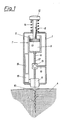
- the device shown in Fig. 1 has a attached to a housing 1, single-lumen subcutaneous needle 2 with a front opening 2 ', in the wall openings 3 to the surrounding tissue 4 are arranged.
- a pump and suction device 7 consisting of a piston pump 5 and a lever device 6 for conveying the perfusion liquid is arranged in the housing 1.
- an analysis device 11 with sensors (not shown here) for detecting the concentration of the substance to be measured and the marker sizes of the perfusion liquid is directly assigned to the output of the subcutaneous needle 2 .
- the piston 13 of the piston pump 5 which is moved in the pumping direction with the aid of the push button 12, displaces a few microliters of perfusion liquid from the piston chamber 9, the perfusate passing the analysis device 11 for zero point calibration on its way to the subcutaneous needle 2.
- a spring 14 resting against the housing 1 and the push button 12 is tensioned.
- a multi-way valve 15 is arranged in the connecting line 8, via which an air bubble 17 is sucked in via an opening 16 in the housing 1 to separate the different liquids in the connecting line 8 can be.
- the measured values are displayed via an evaluation unit 18 connected to the analysis device 11 and a display 19.
- the pump and suction device 7 consists of a precision pump 20, the piston 13 of which is moved by a stepper motor 21.
- the individual suction and pump movements of the precision pump 20, as well as the valve positions of the reusable valve 15 that are required in each case, are controlled by a microprocessor 22.
- the perfusate container is realized by the piston chamber 9 of the piston pump, here the separate perfusate container 23 and the container 24 for the medicament to be administered together with the reusable valve 15 form an exchangeable unit 25, which via the line section 26 of the Connection line 8 is connected to the precision pump 20.
- an elastically deformable membrane 43 can be arranged in front of the septum 28.
- medication containers 24 could also be attached.
- a container for a fast-acting insulin another medicament container for a long-acting insulin
- another medicament container for raising the blood sugar e.g. Glucagon.
- the line section 26 of the connecting line 8 is closed with a puncture septum 27, via which the unit 25 connects to the working space 29 of the precision pump 20 provided with a needle 28.
- the precision pump can be constructed similarly to that known from microliter pipettes, e.g. a piston that is sealed against the housing with one or more O-rings.
- roller pump that compresses a deformable hose, a diaphragm pump, or a pressure vessel with a compressed medium.
- a favorable place for the arrangement of a roller pump 44 would be given, for example, on a deformable line section 26, since here suction and pumping operations can be carried out without inadvertently pumping liquid into the needle 2 or causing other malfunctions.
- the interior of the line section 26 between the valve 15 and the septum 27 is dimensioned such that the volume of a suction stroke of the precision pump can be absorbed without contaminating the precision pump 20 with its parts remaining in the housing 1 with one of the media to be conveyed.
- the precision pump 20 can be connected in defined working positions to the subcutaneous needle 2, to the perfusate container 23, to the containers 24 for medicines and to the opening 16 for supplying outside air.
- the analysis device 11 with the ion or conductivity sensor 31 and the glucose sensor 32 is connected to the interchangeable unit 25 via a conical plug connection 30, preferably via a luer lock.
- a conical connector 30 'of the same design the subcutaneous needle 2 is connected to the analysis device 11.
- an electrical connection 34 between the analysis device 11 with the glucose sensor 32 and the conductivity meter 31 on the one hand and the evaluation unit 18 can also be made automatically, e.g. could be a plug connection or sliding contacts 35.
- the microprocessor 22 is connected to the evaluation unit 18 via a line 40.
- a small amount of the substance to be measured (glucose) and a marker substance can be added to at least one container 24 for the medicament to be administered (insulin) or a separate container, the concentration of which is in the range of the concentrations usually observed.
- a marker substance e.g. sodium chloride
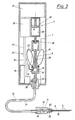
- FIG. 3 shows a further possible embodiment of the device, which is specifically intended to remain in contact with the patient longer as an "artificial pancreas".
- This embodiment differs essentially only from that shown in Fig. 2, as between the plug connection 30, which establishes the connection to the reusable valve 15, on the one hand, and the analysis device 11, on the other hand, there is a flexible connecting line 33, so that the needle 2, for example in this Case can be made of soft, atraumatic material, can be easily attached to the subcutaneous tissue, and the rest of the device is attached elsewhere on the body.
- This has the advantage that Changes in position of the device can not exert any tension or pressure on the needle 2.
- the analysis device 11 should be attached as close as possible to the subcutaneous needle 2, the plug connection 30 'between the analysis device 11 and the needle 2 making it possible to exchange the analysis device 11, and the needle 2 can nevertheless remain in the tissue. Otherwise, the analysis device 11 could of course also be connected directly to the needle 2.
- the connecting line 33 transporting the liquids
- a preamplifier 36 can also be accommodated in the analysis device 11.
- the knob 39 for changing the flow cross section is arranged at the input of the analysis device 11.
- an additional collecting container 37 which, after the measurement, picks up the used perfusate so that it does not have to be pumped into the body.
- This collecting container 37 can also be made from easily deformable material.
- the O-ring seal which can be used in place of the puncture septum 27 and needle 28, sterility being provided by attaching a cap, not shown, prior to inserting the replaceable unit 25. This cap is only removed immediately before the unit 25 is inserted into the device.
- the subcutaneous needle 2 in the region of the front opening 2 ' have a slit-shaped extension 42, which also increases the exchange area of the subcutaneous needle 2.
- the extension can also connect directly to the front opening 2 '.
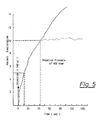
- the dashed lines show the equilibration of 5% and 10% of the tissue fluid achieved after 10 and 40 seconds, respectively.
Abstract
Description
Die Erfindung betrifft eine Vorrichtung zur Bestimmung der Konzentration von zumindest einer in organischem Gewebe vorliegenden Substanz, vorzugsweise der Glucosekonzentration, mit einer ins Gewebe einbringbaren Subcutannadel, wobei eine Pump- und Saugeinrichtung zur Zufuhr einer Perfusionsflüssigkeit und zur Abfuhr nach deren teilweisen Equilibration mit dem Gewebe vorhanden ist und der Grad der Wechselwirkung mit dem Gewebe durch endogene oder exogene Markergrößen der Perfusionsflüssigkeit bestimmbar ist, sowie mit einer Analyseneinrichtung mit Meßeinrichtungen zur Erfassung der Konzentration der zu bestimmenden Substanz und der Markergrößen.The invention relates to a device for determining the concentration of at least one substance present in organic tissue, preferably the glucose concentration, with a subcutaneous needle that can be inserted into the tissue, a pump and suction device being provided for supplying a perfusion liquid and for removing it after its partial equilibration with the tissue is and the degree of interaction with the tissue can be determined by endogenous or exogenous marker sizes of the perfusion liquid, and with an analysis device with measuring devices for detecting the concentration of the substance to be determined and the marker sizes.
Im medizinischen Bereich besteht häufig die Notwendigkeit einer oftmaligen oder auch kontinuierlichen Analyse der Zusammensetzung der Körperflüssigkeiten, um Störungen der Homöostase zu erfassen und beseitigen zu können. Um häufiges Blutabnehmen unnotwendig zu machen, gibt es seit vielen Jahren Versuche, Sensoren im Körper von Patienten zu plazieren, um laufend Informationen zu erhalten.In the medical field there is often a need for frequent or continuous analysis of the composition of body fluids in order to detect and eliminate disorders of homeostasis. In order to make frequent blood sampling unnecessary, attempts have been made for many years to place sensors in the body of patients in order to obtain information continuously.
Eine besonders gefragte Anwendung dabei ist die kontinuierliche Bestimmung der Glucosekonzentration im Organismus. Aus den US-PSen 4 221 567, 4 253 456 und 4 516 580 sind beispielsweise Verfahren und Vorrichtungen zur Dialyse bekannt, bei welchen zumindest eine Kanüle oder Katheter in den Blutstrom eingebracht wird. Über Dialysemembranen wird eine komplette Equilibration einer Meßflüssigkeit mit dem Blut erreicht, welche anschließend auf die interessierende Substanz, beispielsweise Glucose, analysiert wird. Bei den auf einer Seite von der Meßflüssigkeit und auf der anderen Seite von der Körperflüssigkeit, beispielsweise von Blut, beaufschlagten Membranen, welche für eine ausreichende Equilibration genügend groß sein müssen, kommt es jedoch bald zu Verunreinigungen bzw. zu einer Verstopfung der Membranen durch Körpersubstanzen, sodaß der Austausch der interessierenden Stoffe rasch behindert wird. Bei den in den Blutstrom eingebrachten Fremdkörpern, wie Kanülen und Kathetern, besteht zudem die ständige Gefahr der Infektion, der Thrombose oder der Embolie. Außerdem stehen für über längere Zeit aufrecht zu erhaltende Therapien nur wenige Blutgefäße zur Verfügung, welche bald thrombosieren, sodaß das Verfahren nicht fortgesetzt werden kann.A particularly sought after application is the continuous determination of the glucose concentration in the organism. Methods and devices for dialysis are known from US Pat. Nos. 4,221,567, 4,253,456 and 4,516,580, for example, in which at least one cannula or catheter is introduced into the blood stream. A complete equilibration of a measuring liquid with the blood is achieved via dialysis membranes, which is then analyzed for the substance of interest, for example glucose. In the case of the membranes loaded on one side by the measuring liquid and on the other side by the body fluid, for example blood, which are sufficient for adequate equilibration must be large, however, there will soon be contamination or blockage of the membranes by body substances, so that the exchange of the substances of interest is quickly hindered. In the case of foreign bodies introduced into the bloodstream, such as cannulas and catheters, there is also the constant risk of infection, thrombosis or embolism. In addition, there are only a few blood vessels available for therapies to be maintained over a longer period of time, which will soon thrombose, so that the process cannot be continued.
Dazu ist nun aus der WO88/05643 eine Vorrichtung der eingangs genannten Art bekanntgeworden, welche die oben angeführten Nachteile vermeidet. Eine als "Glucose-Pen" bezeichnete Ausführungsform weist hier ein annähernd schreibstiftförmig gestaltetes Gehäuse auf, das an seinem einen Ende eine Subcutannadel aufweist. Im Inneren des Gehäuses befindet sich eine Kolbenpumpe mit einem Reservoir für die Perfusionsflüssigkeit, aus welchem mit Hilfe des Kolbens sowohl das Perfusat durch Verdrängung aus dem Kolbenraum herausgepumpt als auch in den hinter dem Kolben freiwerdenden Auffangbehälter angesaugt werden kann. Mit Hilfe einer Hebeleinrichtung kann über ein allenfalls notwendiges Getriebe der Kolben manuell bewegt werden und Perfusionsflüssigkeit mittels eines ersten Lumens in der Subcutannadel an die Öffnungen in deren Wand gebracht und gleichzeitig durch ein zweites, beispielsweise konzentrisch dazu angeordnetes Lumen durch den Sog im Auffangbehälter gesammelt werden. Möglichst knapp an der Subcutannadel ist dabei anschließend an die abführende Leitung eine Analyseneinrichtung mit einer Meßkapillare für die zu bestimmende Substanz und die Markergröße angebracht. Es kann somit für kurze Zeit, z.B. in der Größenordnung von ca. 1 Minute oder weniger, Flüssigkeit durch die Subcutannadel gepumpt und nach deren teilweisen Equilibration wieder gesammelt werden. Bereits nach kurzer Zeit kann über eine optische Anzeige oder auch eine akustische Anzeige die wahre Konzentration der interessierenden Substanz, beispielsweise des Blutzuckers, erfaßt werden, die von der Analyseneinheit aus der Konzentration der Markersubstanz und der interessierenden Substanz errechnet wird. Um während der erforderlichen Zeit der Gewebeperfusion eine gleichmäßige Flußrate zu erhalten, sind mehrere Vorgangs weisen denkbar. So kann z.B. über die Hebeleinrichtung deren Hebel während der Perfusionsperiode immer wieder betätigt wird, eine gleichmäßige Perfusionsrate erzielt werden. Der Hebel kann dazu, beispielsweise über eine Feder oder einen anderen Energiespeicher, immer wieder in seine Ausgangslage gebracht werden. Die Perfusionsrate während der Sammelperiode liegt dabei in der Größenordnung zwischen 1 und 10 µl/min. Nachteilig dabei ist lediglich der komplizierte Aufbau dieses "Glucose-Pen", wobei insbesondere die Herstellung der mehrlumigen Subcutannadel technisch schwierig und kostenintensiv ist.For this purpose, a device of the type mentioned at the outset has become known from WO88 / 05643, which avoids the disadvantages mentioned above. An embodiment referred to as a “glucose pen” here has an approximately pen-shaped housing which has a subcutaneous needle at one end. Inside the housing there is a piston pump with a reservoir for the perfusion liquid, from which the piston can be used to pump the perfusate out of the piston chamber as well as suck it into the collection container that is released behind the piston. With the help of a lever device, the piston can be manually moved via a possibly necessary gear and perfusion liquid can be brought to the openings in the wall by means of a first lumen in the subcutaneous needle and at the same time collected by the suction in the collecting container by a second, for example concentrically arranged lumen. An analyzer with a measuring capillary for the substance to be determined and the marker size is attached to the draining line as close as possible to the subcutaneous needle. Liquid can therefore be pumped through the subcutaneous needle for a short time, for example in the order of magnitude of approximately 1 minute or less, and collected again after its partial equilibration. After a short time, the true concentration of the substance of interest, for example blood sugar, can be detected via an optical display or an acoustic display, which is calculated by the analysis unit from the concentration of the marker substance and the substance of interest. There are several procedures to maintain a steady flow rate during the required time of tissue perfusion show possible. For example, a constant perfusion rate can be achieved via the lever device, the lever of which is repeatedly operated during the perfusion period. For this purpose, the lever can be brought into its starting position again and again, for example by means of a spring or another energy store. The perfusion rate during the collection period is in the order of 1 to 10 µl / min. The only disadvantage is the complicated structure of this "glucose pen", the production of the multi-lumen subcutaneous needle in particular being technically difficult and cost-intensive.
Aufgabe der Erfindung ist es, eine Vorrichtung vorzuschlagen, welche ausgehend vom genannten Stand der Technik einfacher und kostengünstiger herstellbar ist, wobei die wesentlichen Vorteile der gattungsgemäßen Vorrichtung erhalten bleiben sollen.The object of the invention is to propose a device which, based on the prior art mentioned, can be produced more easily and cost-effectively, the main advantages of the generic device being retained.
Diese Aufgabe wird erfindungsgemäß dadurch gelöst, daß eine einlumige Subcutannadel vorgesehen ist, deren Lumen mit der Analyseneinrichtung verbindbar ist, daß die Analyseneinrichtung ausgangsseitig an die Pump- und Saugeinrichtung angeschlossen ist, sowie daß die Strömungsrichtung der Perfusionsflüssigkeit im Lumen der Subcutannadel beim Wechsel vom Pump- zum Saugbetrieb umkehrbar ist. Mit dieser sehr einfachen Vorrichtung werden nach dem Einstechen der Subcutannadel wenige µl Perfusat in die Subcutannadel gepumpt, wobei die Perfusionslösung die Analyseneinrichtung passiert und eine Nullpunktseichung vorgenommen werden kann. Nach teilweiser Equilibration des Perfusates mit dem an der Subcutannadel anstehenden Gewebe wird das Perfusat aus der Nadel gesaugt und wieder mit den Sensoren der Analyseneinrichtung in Kontakt gebracht, wobei die zu bestimmende Substanz und die Markergröße, z.B. die elektrische Leitfähigkeit, gemessen und aus diesen Werten die tatsächliche Konzentration, z.B. die Glucosekonzentration, errechnet wird. Zur Nullpunktseichung sollte die Perfusionsflüssigkeit im angeführten Beispiel im wesentlichen ionen- und glucosefrei sein.This object is achieved in that a single-lumen subcutaneous needle is provided, the lumen of which can be connected to the analysis device, the analysis device is connected on the output side to the pump and suction device, and the flow direction of the perfusion liquid in the lumen of the subcutaneous needle when changing from the pump is reversible for suction operation. With this very simple device, a few μl of perfusate are pumped into the subcutaneous needle after the subcutaneous needle has been inserted, the perfusion solution passing through the analysis device and zero point calibration being able to be carried out. After partial equilibration of the perfusate with the tissue attached to the subcutaneous needle, the perfusate is sucked out of the needle and brought back into contact with the sensors of the analysis device, the substance to be determined and the marker size, e.g. the electrical conductivity, measured and from these values the actual concentration, e.g. the glucose concentration is calculated. For the zero point calibration, the perfusion liquid in the example given should be essentially free of ions and glucose.
Als weiterer Vorteil der erfindungsgemäßen Vorrichtung ist anzuführen, daß einlumige Subcutannadeln entsprechend dünner ausgeführt werden können, sodaß der Patient, z.B. bei der mehrmals täglich durchzuführenden Gewebezucker-Analyse, eine geringere Schmerzbelastung zu tragen hat.Another advantage of the device according to the invention is that single-lumen subcutaneous needles can be made correspondingly thinner, so that the patient, for example, in the Tissue sugar analysis to be carried out several times a day has to bear less pain.
Um die Austauschfläche der Subcutannadel zu vergrößern, ist erfindungsgemäß vorgesehen, daß die Subcutannadel entlang der Nadelachse eine schlitzförmige Erweiterung aufweist, bzw. daß die Subcutannadel neben der Frontöffnung zumindest eine weitere Öffnung im Wandbereich aufweist. Vorzugsweise sind mehrere Öffnungen in mehreren Reihen an der Zirkumferenz der Nadel angebracht.In order to enlarge the exchange area of the subcutaneous needle, it is provided according to the invention that the subcutaneous needle has a slit-shaped extension along the needle axis, or that the subcutaneous needle has at least one further opening in the wall area in addition to the front opening. Preferably, multiple openings are made in multiple rows on the circumference of the needle.
In einer Ausgestaltung der Erfindung ist vorgesehen, daß die Analyseneinrichtung an beiden Seiten eine konische Steckverbindung, aufweist, mit dem die Analyseneinrichtung auf der einen Seite mit der Subcutannadel und auf der anderen Seite über eine Verbindungsleitung mit der Pump- und Saugeinrichtung verbunden ist, wobei die Steckverbindung über lösbare Kontakte eine elektrische Verbindung zwischen Auswerteeinheit und Analyseneinrichtung herstellt. Die Steckverbindungen garantieren ein einfaches Wechseln der Nadel bzw. der Analyseneinrichtung.In one embodiment of the invention it is provided that the analysis device has a conical plug connection on both sides, with which the analysis device is connected on one side to the subcutaneous needle and on the other side via a connecting line to the pump and suction device, the Plug connection via detachable contacts creates an electrical connection between the evaluation unit and the analysis device. The plug connections guarantee easy changing of the needle or the analysis device.
Um dafür Sorge zu tragen, daß die teilweise equilibrierte Perfusionsflüssigkeit sich nicht mit der Perfusionsflüssigkeit in der Kolbenpumpe vermischen kann, ist in einer Weiterbildung der Erfindung vorgesehen, daß zwischen der Pump- und Saugeinrichtung und der Analyseneinrichtung ein Mehrwegventil angeordnet ist, über welche die Pump- und Saugeinrichtung in einer ersten Stellung des Ventils mit der Subcutannadel und in einer zweiten Stellung mit einer Öffnung zur Zufuhr von Außenluft in Verbindung steht. Die über das Ventil einsaugbare Luftblase trennt dann die beiden Flüssigkeitssäulen.In order to ensure that the partially equilibrated perfusion liquid cannot mix with the perfusion liquid in the piston pump, a further development of the invention provides that a multi-way valve is arranged between the pump and suction device and the analysis device, via which the pump and suction device in a first position of the valve with the subcutaneous needle and in a second position with an opening for supplying outside air. The air bubble that can be sucked in via the valve then separates the two liquid columns.
In einer Ausgestaltung der Erfindung ist vorgesehen, daß die Pump- und Saugeinrichtung eine Kolbenpumpe aufweist, deren Kolbenraum als Perfusionsbehälter ausgeführt ist, sowie daß für den Saughub ein während des Pumphubes aufgeladener Energiespeicher vorgesehen ist. Bei der vorzugsweise von Hand betätigbaren Kolbenpumpe muß der Patient lediglich nach dem Einstechen eine Hebeleinrichtung drücken und später loslassen, wodurch der Analysiervorgang automatisch abläuft. Als Energiespeicher dient beispielsweise eine Feder. Durch kleine Pumpbewegungen während des Equilibriervorganges kann die Strö mungsrichtung des Perfusates im Lumen der Subcutannadel mehrfach umgekehrt werden, wodurch ein höherer Equilibrationsgrad erreicht wird.In one embodiment of the invention, it is provided that the pump and suction device has a piston pump, the piston chamber of which is designed as a perfusion container, and that an energy store charged during the pump stroke is provided for the suction stroke. In the piston pump, which can preferably be operated by hand, the patient only has to press a lever device after the piercing and release it later, as a result of which the analysis process runs automatically. A spring, for example, serves as an energy store. By small pumping movements during the equilibration process, the Strö Direction of perfusate in the lumen of the subcutaneous needle are reversed several times, whereby a higher degree of equilibration is achieved.
Eine vorteilhafte Weiterbildung der Erfindung liegt darin, daß im Pumpenantrieb ein Mechanismus vorgesehen ist, welcher zwischen Pump- und Saughub, in der Equilibrierphase der Perfusionsflüssigkeit, für kleine Pump- und Saugbewegungen des Kolbens der Kolbenpumpe sorgt. Damit werden die Pumpbewegungen in der Equilibrationsphase von einem Mechanismus ausgeführt, welchem die erforderliche Energie ebenfalls über die den Pumphub auslösende Hebeleinrichtung zugeführt werden kann.An advantageous development of the invention is that a mechanism is provided in the pump drive, which ensures small pumping and suctioning movements of the piston of the piston pump between pump and suction stroke, in the equilibration phase of the perfusion liquid. The pump movements in the equilibration phase are thus carried out by a mechanism to which the required energy can also be supplied via the lever device which triggers the pump stroke.
Es kann in einer erfindungsgemäßen Weiterbildung auch vorgesehen sein, daß ein Perfusionsbehälter und zumindest ein Behälter für ein zu verabreichendes Medikament vorgesehen ist, sowie daß die Pump- und Saugeinrichtung in einer dritten Stellung des Mehrwegventils mit dem Perfusionsbehälter, und in zumindest einer weiteren Stellung mit je einem Behälter für ein Medikament in Verbindung steht.In a further development according to the invention it can also be provided that a perfusion container and at least one container for a medicament to be administered is provided, and that the pump and suction device in a third position of the reusable valve with the perfusion container, and in at least one further position with each communicates with a container for a medicament.
Erfindungsgemäß kann dabei ein Behälter für ein rasch wirksames Insulin, ein Behälter für lange wirkendes Insulin und ein Behälter für ein blutzuckersteigerndes Hormon vorgesehen sein.According to the invention, a container for a fast-acting insulin, a container for long-acting insulin and a container for a hormone that increases blood sugar can be provided.
Eine Weiterbildung nach der Erfindung sieht vor, daß der Perfusionsbehälter und die Behälter für Medikamente leicht verformbare Beutel aus Kunststoff sind und gemeinsam mit dem Mehrwegventil und den entsprechenden Verbindungsleitungen eine austauschbare Einheit bilden. Damit kann dann die aufgrund des Meßwertes der Konzentration der zu bestimmenden Substanzen erkennbare, erforderliche Medikamentenmenge ohne weitere Stichbelastung des Patienten über die bereits eingeführte Subcutannadel appliziert werden. Nachdem der Perfusionsbehälter bzw. der Behälter für das Medikament entleert ist, können diese mitsamt dem Mehrwegventil und den erforderlichen Verbindungsleitungen als Einheit gegen eine neue ausgewechselt werden.A further development according to the invention provides that the perfusion container and the container for medication are easily deformable plastic bags and form an interchangeable unit together with the reusable valve and the corresponding connecting lines. The required amount of medication, which can be identified on the basis of the measured value of the concentration of the substances to be determined, can then be applied via the already inserted subcutaneous needle without further puncturing the patient. After the perfusion container or the container for the medication has been emptied, they can be replaced together with the reusable valve and the necessary connecting lines as a unit for a new one.
Dabei ist in einer Weiterbildung der Erfindung vorgesehen, daß die austauschbare Einheit über eine druckdichte Verbindung, vorzugsweise über ein Durchstichseptum oder eine O-Ringdichtung mit der Pump- und Saugeinrichtung in Verbindung steht, wobei der Innenraum des zwischen dem Mehrwegventil und der druckdichten Verbindung liegenden Leitungsabschnittes der Verbindungsleitung dem Volumen zumindest eines Saughubes entspricht. Der zwischen Septum bzw. O-Ring-Dichtstelle und Mehrwegventil liegende Leitungsabschnitt kann aufgrund seines Innenvolumens einen Saughub zur Gänze aufnehmen, wodurch die anschließende Pump- und Saugeinrichtung nicht kontaminiert wird. Das benötigte Volumen kann entweder durch eine aufgerollte Kapillarleitung oder durch entsprechend geräumige Erweiterungen in der Leitung realisiert werden, wobei eine Kapillarleitung allerdings den Vorteil hat, daß sie ein Funktionieren der Vorrichtung völlig lageunabhängig gewährleistet, da sich die Flüssigkeitssäule in der Kapillare nicht unabsichtlich mit Luft durchmischen kann.It is provided in a development of the invention that the interchangeable unit via a pressure-tight connection, preferably via a puncture septum or O-ring seal is connected to the pumping and suction device, the interior of the line section of the connecting line lying between the reusable valve and the pressure-tight connection corresponding to the volume of at least one suction stroke. The line section located between the septum or O-ring sealing point and the reusable valve can completely absorb a suction stroke due to its internal volume, as a result of which the subsequent pumping and suctioning device is not contaminated. The required volume can either be realized by a rolled-up capillary line or by correspondingly spacious extensions in the line, but a capillary line has the advantage that it ensures the functioning of the device completely independent of position, since the liquid column in the capillary does not accidentally mix with air can.
Um eine Kontamination der Pump- und Saugeinrichtung sicher zu vermeiden, ist entsprechend einer Weiterbildung der Erfindung vorgesehen, daß die austauschbare Einheit zwischen der druckdichten Verbindung und dem Mehrwegventil eine durch den anliegenden Druck elastisch verformbare Membran aufweist. Es ist auch möglich, anstelle der Membran ein gasduchlässiges Bakterienfilter zu verwenden, welches für Flüssigkeiten undurchlässig ist.In order to reliably avoid contamination of the pump and suction device, it is provided according to a development of the invention that the interchangeable unit between the pressure-tight connection and the reusable valve has a membrane which can be elastically deformed by the applied pressure. It is also possible to use a gas-permeable bacterial filter instead of the membrane, which is impermeable to liquids.
Falls die Vorrichtung für längere Zeit am Patienten verbleiben soll, ist es von Vorteil, wenn zwischen der konischen Steckverbindung zum Mehrwegventil und der Analyseneinrichtung eine verformbare Verbindungsleitung und eine elektrische Verbindung vorgesehen sind. Die Subcutannadel samt Analyseneinrichtung bildet hier eine Einheit, welche mit dem die übrigen Komponenten der Vorrichtung beinhaltenden Gehäuse beweglich verbunden ist.If the device is to remain on the patient for a long time, it is advantageous if a deformable connecting line and an electrical connection are provided between the conical plug connection to the reusable valve and the analysis device. The subcutaneous needle together with the analysis device forms a unit which is movably connected to the housing containing the other components of the device.
Für Fälle, wo nicht das gesamte verbrauchte Perfusat in das Gewebe abgeleitet werden kann, ist es vorteilhaft, wenn ein Auffangbehälter für die Perfusionsflüssigkeit vorgesehen ist, welcher über eine Stellung des Mehrwegventils mit der Pump- und Saugeinrichtung in Verbindung steht.In cases where not all of the perfusate used up can be drained into the tissue, it is advantageous if a collecting container for the perfusion liquid is provided, which is connected to the pump and suction device via a position of the reusable valve.
Die Pump- und Saugeinrichtung kann somit ohne Reinigung und Wartung für lange Zeit im Gehäuse der Vorrichtung verbleiben, womit erfindungsgemäß eine von einem Mikroprozessor gesteuerte Präzisionspumpe verwendet werden kann, welche den großen Anforderungen im Hinblick auf Sicherheit und Reproduzierbarkeit gerecht ist. Der Mikroprozessor steuert gleichzeitig auch das Mehrwegventil, wobei über ein geeignetes Display für den Benutzer lediglich Hinweise, wie "Nadel aufstecken", "Nadel einstechen", "Nadel entfernen", etc. aufscheinen.The pump and suction device can therefore remain in the housing of the device for a long time without cleaning and maintenance, with which, according to the invention, a precision pump controlled by a microprocessor can be used which meets the great requirements with regard to safety and reproducibility. The microprocessor also controls the reusable valve at the same time, with only suitable indications such as "inserting the needle", "inserting the needle", "removing the needle", etc. appearing on the user.
Die Verabreichung des langsam wirkenden Insulins, die des rasch wirkenden Insulins sowie der blutzuckersteigernden Substanz kann vorteilhafterweise über den Mikroprozessor der Auswerteeinheit gesteuert werden. Dabei ist es von Vorteil, wenn die Gewebszuckerwerte und die abgegebenen Insulinmengen in einem Speicher über möglichst lange Zeit gespeichert werden, damit die errechneten Algorithmen für die Insulingabe durch einen Lerneffekt im Laufe der Zeit verbessert werden können. Es ist auch möglich, die Pump- bzw. Saugleistung der Pump- und Saugeinrichtung mit Hilfe des Mikroprozessors so zu steuern, daß die Markergröße, beispielsweise die Leitfähigkeit, im wesentlichen konstant bleibt. Nach Erreichen einer wünschenswerten Equilibration zwischen 5 bis 20 % der Gewebekonzentration kann die Saugeinrichtung eventuell abgeschaltet werden.The administration of the slow-acting insulin, that of the fast-acting insulin and the blood sugar-increasing substance can advantageously be controlled via the microprocessor of the evaluation unit. It is advantageous if the tissue sugar values and the insulin quantities released are stored in a memory for as long as possible, so that the calculated algorithms for insulin administration can be improved over time by a learning effect. It is also possible to control the pumping or suction power of the pumping and suctioning device with the aid of the microprocessor so that the marker size, for example the conductivity, remains essentially constant. After reaching a desirable equilibration between 5 to 20% of the tissue concentration, the suction device can possibly be switched off.
Weiters ist erfindungsgemäß vorgesehen, daß zur raschen Umkehr der der Strömungsrichtung der Perfusionsflüssigkeit ein während des Pumpbetriebes der Präzisionspumpe mit Unterdruck beaufschlagter Pumpenraum im Saugbetrieb in einer weiteren Stellung des Ventiles über eine Verbindungsleitung mit der Subcutannadel verbindbar ist.It is further provided according to the invention that for rapid reversal of the direction of flow of the perfusion liquid, a pump chamber which is pressurized during the pumping operation of the precision pump can be connected to the subcutaneous needle in a further position of the valve in a further position of the valve.
Vor allem dann, wenn die Analyseneinrichtung über eine flexible Verbindungsleitung mit dem Gehäuse der Vorrichtung verbunden ist und lange Signalwege vorhanden sind, ist erfindungsgemäß vorgesehen, daß in der Analyseneinrichtung ein Vorverstärker eingebaut ist.Especially when the analysis device is connected to the housing of the device via a flexible connecting line and long signal paths are present, the invention provides that a preamplifier is installed in the analysis device.
In allen Ausführungsvarianten kann die Analyseneinrichtung zur besseren Durchmischung der zu messenden Flüssigkeit eingangsseitig eine Veränderung des Strömungsquerschnittes, z.B. in Form einer Noppe, aufweisen, welche in den Perfusatstrom ragt und die Perfusionsflüssigkeit verwirbelt.In all design variants, the analysis device can have a change in the flow cross-section, for example in the form of a knob, on the inlet side for better mixing of the liquid to be measured, which changes into the perfusate stream and swirls the perfusion liquid.
Zur besseren Absicherung der Meßergebnisse kann von der Analyseneinrichtung zuerst die Konzentration der Markergröße, anschließend die Konzentration der interessierenden Substanz und anschließend zumindest noch einmal die Konzentration der Markergröße bestimmt werden, bzw. in zwei unabhängigen Meßkreisen die Markergröße und die Konzentration der interessierenden Substanz gleichzeitig und kontinuierlich gemessen werden, und aus diesen Messungen die tatsächliche Konzentration der interessierenden Substanz, z.B. des Gewebezuckers, errechnet werden.To better safeguard the measurement results, the analysis device can first determine the concentration of the marker size, then the concentration of the substance of interest and then at least once again the concentration of the marker size, or the marker size and the concentration of the substance of interest simultaneously and continuously in two independent measuring circuits are measured, and from these measurements the actual concentration of the substance of interest, eg of sugar in the tissue can be calculated.
Schließlich ist erfindungsgemäß vorgesehen, daß in der Analyseneinrichtung ein kombinierter Ionen- oder Leitfähigkeitssensor sowie ein Glucosesensor vorgesehen sind, wobei die Analyseneinrichtung mit den kombinierten Sensoren ein Füllvolumen von ca. 10 µl oder weniger aufweist.Finally, it is provided according to the invention that a combined ion or conductivity sensor and a glucose sensor are provided in the analysis device, the analysis device with the combined sensors having a filling volume of approximately 10 μl or less.
Die Erfindung wird im folgenden anhand von Zeichnungen näher erläutert. Es zeigen:
Figur 1 eine Vorrichtung nach der Erfindung in schematischer Darstellung,Figur 2 und 3 Ausführungsvarianten nach Fig. 1,- Figur 4a und 4b Ausführungsvarianten der Vorrichtung im Detail und
Figur 5 eine Meßkurve.
- FIG. 1 shows a device according to the invention in a schematic illustration,
- 2 and 3 design variants according to FIG. 1,
- Figure 4a and 4b variants of the device in detail and
- Figure 5 is a measurement curve.
Die in Fig. 1 dargestellte Vorrichtung weist eine an einem Gehäuse 1 befestigte, einlumige Subcutannadel 2 mit einer Frontöffnung 2′ auf, in deren Wand Öffnungen 3 zum umliegenden Gewebe 4 angeordnet sind. Im Gehäuse 1 ist eine aus einer Kolbenpumpe 5 und einer Hebeleinrichtung 6 bestehende Pump- und Saugeinrichtung 7 zur Förderung der Perfusionsflüssigkeit angeordnet. In der Verbindungsleitung 8, zwischen dem Kolbenraum 9 der Kolbenpumpe 5 und dem Lumen 10 der Subcutannadel 2, ist direkt dem Ausgang der Subcutannadel 2 eine Analyseneinrichtung 11 mit hier nicht näher dargestellten Sensoren zur Erfassung der Konzentration der zu messenden Substanz und der Markergrößen der Perfusionsflüssigkeit zugeordnet.The device shown in Fig. 1 has a attached to a
Der mit Hilfe des Druckknopfes 12 in Pumprichtung bewegte Kolben 13 der Kolbenpumpe 5 verdrängt einige Mikroliter Perfusionsflüssigkeit aus dem Kolbenraum 9, wobei das Perfusat auf seinem Weg zur Subcutannadel 2 die Analyseneinrichtung 11 zur Nullpunktskalibrierung passiert. Gleichzeitig wird eine am Gehäuse 1 und am Druckknopf 12 anliegende Feder 14 gespannt. Durch kleine Pumpbewegungen an der Hebeleinrichtung kann nun eventuell zusätzlich für eine mehrmalige Umkehr der Strömungsrichtung des Perfusates im Lumen 10 der Subcutannadel 2 gesorgt werden, wodurch eine ausreichende Equilibration erreicht wird. Nach dem Loslassen des Druckknopfes 12 der Hebeleinrichtung 6 wird über die Feder 14 der Saughub bewerkstelligt und das teilweise equilibrierte Perfusat wieder mit der Analyseneinrichtung 11 in Kontakt gebracht und gemessen.The
Um zu verhindern, daß sich bereits equilibriertes Perfusat und frisches Perfusat aus dem Kolbenraum 9 vermischen, ist in der Verbindungsleitung 8 ein Mehrwegventil 15 angeordnet, über welches über eine Öffnung 16 im Gehäuse 1 eine Luftblase 17 zur Trennung der unterschiedlichen Flüssigkeiten in der Verbindungsleitung 8 eingesaugt werden kann.In order to prevent that already perfused perfusate and fresh perfusate from the
Über eine an die Analyseneinrichtung 11 angeschlossene Auswerteeinheit 18 und ein Display 19 gelangen die gemessenen Werte zur Anzeige.The measured values are displayed via an
Bei der in Fig. 2 dargestellten Ausführungsvariante besteht die Pump- und Saugeinrichtung 7 aus einer Präzisionspumpe 20, deren Kolben 13 von einem Schrittmotor 21 bewegt wird. Die einzelnen Saug- und Pumpbewegungen der Präzisionspumpe 20, sowie die jeweils notwendigen Ventilstellungen des Mehrwegventils 15 werden von einem Mikroprozessor 22 gesteuert. Während in der Ausführung nach Fig. 1 der Perfusatbehälter durch den Kolbenraum 9 der Kolbenpumpe realisiert wird, bilden hier der separate Perfusatbehälter 23 und der Behälter 24 für das zu verabreichende Medikament zusammen mit dem Mehrwegventil 15 eine auswechselbare Einheit 25, welche über den Leitungsabschnitt 26 der Verbindungsleitung 8 mit der Präzisionspumpe 20 verbunden ist.In the embodiment variant shown in FIG. 2, the pump and
Um die Präzisionspumpe 20 vor Kontaminationen zu schützen, kann vor dem Septum 28 eine elastisch verformbare Membran 43 angeordnet sein.In order to protect the
Bei Verwendung von mehr als einem Medikament zur Korrektur der festgestellten Störung, könnten auch mehrere Medikamentenbehälter 24 angebracht sein. So könnte z.B. im Falle der Zuckermessung ein Behälter für ein rasch wirksames Insulin, ein anderer Medikamentenbehälter für ein lang wirkendes Insulin, und ein weiterer Medikamentenbehälter zur Hebung des Blutzuckers, z.B. Glucagon, vorhanden sein.If more than one medication is used to correct the detected disorder,
Der Leitungsabschnitt 26 der Verbindungsleitung 8 ist mit einem Durchstichseptum 27 verschlossen, über welches die Einheit 25 an den mit einer Nadel 28 versehenen Arbeitsraum 29 der Präzisionspumpe 20 anschließt. Die Präzisionspumpe kann dabei ähnlich aufgebaut sein, wie sie von Mikroliterpipetten bekannt ist, z.B. ein Kolben, der mit einem oder mehreren O-Ringen gegen das Gehäuse abgedichtet ist.The
Es ist auch möglich andere Pumpen, wie z.B. eine Rollenpumpe, die einen verformbaren Schlauch komprimiert, eine Membranpumpe, oder einen Druckbehälter mit einem komprimierten Medium, zu verwenden. Ein günstiger Platz für die Anordnung einer Rollenpumpe 44 wäre beispielsweise an einem verformbar ausgebildeten Leitungsabschnitt 26 gegeben, da hier Saug- und Pumpvorgänge durchgeführt werden können, ohne unbeabsichtigt Flüssigkeit in die Nadel 2 zu pumpen, bzw. andere Fehlfunktionen herbeizuführen.It is also possible to use other pumps, e.g. a roller pump that compresses a deformable hose, a diaphragm pump, or a pressure vessel with a compressed medium. A favorable place for the arrangement of a
Der Innenraum des Leitungsabschnittes 26 zwischen dem Ventil 15 und dem Septum 27 ist so dimensioniert, daß das Volumen eines Saughubes der Präzisionspumpe aufgenommen werden kann, ohne die Präzisionspumpe 20 mit ihren im Gehäuse 1 verbleibenden Teilen mit einem der zu fördernden Medien zu kontaminieren. Mit Hilfe des Ventils 15 kann die Präzisionspumpe 20 in definierten Arbeitsstellungen mit der Subcutannadel 2, mit dem Perfusatbehälter 23, mit den Behältern 24 für Medikamente sowie mit der Öffnung 16 zur Zufuhr von Außenluft verbunden werden.The interior of the
Weiters ist es auch möglich, die Subcutannadel 2 über das Ventil 15 und eine in Fig. 2 strichliert angedeutete Verbindungsleitung 40 mit dem hinter dem Kolben 13 liegenden Pumpenraum 41 der Pumpe 20 zu verbinden. Der während des Pumpenhubes im Pumpenraum 41 erzeugte Unterdruck sorgt dann für eine rasche Umkehr der Strömungsrichtung des Perfusates in der Subcutannadel 2.Furthermore, it is also possible to connect the
Die Analyseneinrichtung 11 mit dem Ionen- oder Leitfähigkeitssensor 31 und dem Glucosesensor 32 steht mit der auswechselbaren Einheit 25 über eine konische Steckverbindung 30, vorzugsweise über einen Luerverschluß, in Verbindung. Mit einer konischen Steckverbindung 30′ gleicher Bauart ist die Subcutannadel 2 mit der Analyseneinrichtung 11 verbunden.The
Dabei kann automatisch auch eine elektrische Verbindung 34 zwischen Analysenvorrichtung 11 mit dem Glucosesensor 32 und dem Leitfähigkeitsmesser 31 einerseits und der Auswerteeinheit 18 bewerkstelligt werden, wobei es sich z.B. um eine Steckverbindung oder Gleitkontakte 35 handeln könnte. Der Mikroprozessor 22 steht über eine Leitung 40 mit der Auswerteeinheit 18 in Verbindung.In this case, an
Zumindest einem Behälter 24 für das zu verabreichende Medikament (Insulin) oder einem separaten Behälter kann eine geringe Menge der zu messenden Substanz (Glucose) sowie einer Markersubstanz (z.B. Natriumchlorid) zugesetzt sein, wobei deren Konzentration im Bereich der üblicherweise beobachteten Konzentrationen liegt.A small amount of the substance to be measured (glucose) and a marker substance (e.g. sodium chloride) can be added to at least one
Fig. 3 zeigt eine weitere mögliche Ausführungsform der Vorrichtung, die speziell dafür gedacht ist, als "künstliches Pankreas" länger mit dem Patienten in Verbindung zu stehen. Diese Ausführungsform unterscheidet sich im wesentlichen nur insoferne von der in Fig. 2 gezeigten, als zwischen der Steckverbindung 30, die die Verbindung zum Mehrwegventil 15 herstellt einerseits und der Analyseneinrichtung 11 andererseits eine flexible Verbindungsleitung 33 besteht, sodaß die Nadel 2, die z.B. in diesem Fall aus weichem, atraumatischem Material bestehen kann, leicht im subcutanene Gewebe angebracht werden kann, und die übrige Vorrichtung an anderer Stelle am Körper befestigt wird. Dies hat den Vorteil, daß Lageänderungen der Vorrichtung keinen Zug oder Druck auf die Nadel 2 ausüben können. Die Analyseneinrichtung 11 soll möglichst knapp an der Subcutannadel 2 angebracht sein, wobei die Steckverbindung 30′ zwischen Analyseneinrichtung 11 und Nadel 2 einen Austausch der Analyseneinrichtung 11 ermöglicht, und die Nadel 2 trotzdem im Gewebe verbleiben kann. Andernfalls könnte die Analyseneinrichtung 11 natürlich auch direkt mit der Nadel 2 verbunden sein. Neben der die Flüssigkeiten transportierenden Verbindungsleitung 33 muß auch eine elektrische Verbindung 34 zur Auswerteeinheit 18 vorhanden sein, beispielsweise elektrische Kontakte 35, z.B. eine Steckverbindung oder Gleitkontakte, die gleichzeitig mit dem Anschluß der Steckverbindung 30 geschlossen werden. Wenn die Signale von der Analyseneinrichtung 11 oft sehr schwach und störungsanfällig sind, kann in der Analyseneinrichtung 11 auch ein Vorverstärker 36 untergebracht sein. Zur besseren Durchmischung des Perfusates vor der Messung ist am Eingang der Analyseneinrichtung 11 die Noppe 39 zur Veränderung des Strömungsquerschnittes angeordnet.FIG. 3 shows a further possible embodiment of the device, which is specifically intended to remain in contact with the patient longer as an "artificial pancreas". This embodiment differs essentially only from that shown in Fig. 2, as between the
Für den längeren Verbleib der Vorrichtung im Körper bei Verwendung z.B. als künstliches Pankreas oder als anderes "closed feedback" System kann es günstig sein, auch einen zusätzlichen Auffangbehälter 37 zu schaffen, der nach der Messung das verbrauchte Perfusat aufnimmt, damit es nicht in den Körper gepumpt werden muß. Auch dieser Auffangbehälter 37 kann aus leicht verformbarem Material hergestellt sein. Weiters gezeigt ist mit 38 die O-Ringdichtung, die statt des Durchstichseptums 27 und der Nadel 28 verwendet werden kann, wobei durch Anbringen einer Verschlußkappe, die nicht gezeigt ist, vor dem Einsetzen der austauschbaren Einheit 25 für Sterilität gesorgt werden kann. Diese Verschlußkappe wird erst unmittelbar vor dem Einsetzen der Einheit 25 in die Vorrichtung abgenommen.For longer retention of the device in the body when used e.g. as an artificial pancreas or as another "closed feedback" system, it can be favorable to also create an
Wie im Detail in Fig. 4 dargestellt, kann die Subcutannadel 2 im Bereich der Frontöffnung 2′ eine schlitzförmige Erweiterung 42 aufweisen, wodurch ebenfalls die Austauschfläche der Subcutannadel 2 vergrößert wird. Entsprechend Fig. 4b kann die Erweiterung auch direkt an die Frontöffnung 2′ anschließen.As shown in detail in Fig. 4, the
Im Betrieb der erfindungsgemäßen Vorrichtung sind folgende, im wesentlichen automatisch ablaufende Schritte denkbar:
- 1.
Bevor die Subcutannadel 2 in den Körper eingebracht wird, wird durch dieAnalyseneinrichtung 11 eine Lösung geschickt, die ca. eine Menge der zu bestimmenden Substanz und der Markersubstanz enthält, wie sie dann bei der aktuellen Messung erwartet wird, womit die Steilheit der Sensoren ermittelt werden kann. Beispielsweise kann dazu der Medikamentenlösung, z.B. Insulin, die zu bestimmende Substanz , wie z.B Glucose und die Markersubstanz, wie z.B. Natriumchlorid, zugesetzt werden. Anschließend wird überdas Ventil 15 Luft angesaugt und dieVerbindungsleitung 8, sowie dieAnalyseneinrichtung 11 durch Ausstoßen von Luft gereinigt. Anschließend wird ein Perfusat, das frei von zu bestimmender Substanz und Markersubstanz ist, durch dieAnalyseneinrichtung 11 gepumpt um den Nullpunkt nachzueichen. - 2. Nach dem Aufstecken und Einstechen der Subcutannadel wird das Perfusat in die Nadel gepumpt und sehr rasch an die Subcutannadel ein Unterdruck angelegt, um das in die Nadel gepumpte Perfusat wieder zu gewinnen, bevor es im Körper versickern kann. Eventuell kann zusätzlich durch kleine Pumpbewegungen im Lumen der Subcutannadel das Perfusat hin und her bewegt werden bis eine teilweise Equilibration erreicht ist. Im Anschließenden Saughub wird die Konzentration der interessierenden Substanz, z.B. Glucose und die Markergröße, z.B. die Leitfähigkeit als Maß für den Grad der Equilibration gemessen.
- 3. Das inerte Perfusat kann anschließend in den Körper oder wie in Fig. 3 dargelegt, in einen eigenen Auffangbehälter gepumpt werden.
- 4. Anschließend wird das Mehrwegventil umgeschaltet und die erforderliche Menge des Medikamentes, z.B. Insulin oder auch eine blutzuckersteigernde Substanz, wie z.B. Glucagon in das Gewebe gepumpt. Dabei kann auch vom Mikroprozessor 19 aufgrund der erhobenen Meßwerte die optimale Menge des Medikamentes ohne Zutun des Patienten errechnet werden, der Patient kann dann eventuell die vorgeschlagene Menge des Medikamentes durch Tastendruck bestätigen.
- 5. Nach der Applikation der Medikamentes wird über
das Ventil 15 nochmals eine Verbindung zur Außenluft oder zum Perfusionsbehälter hergestellt und der Rest des Medikamentes mit der Perfusionsflüssigkeit oder mit Luft aus der Subcutannadel in das Gewebe gespült. - 6. Bei Anwendung der Vorrichtung als künstliches "Pankreas" kann die Nadel im Körper verbleiben und der Meßvorgang und die Insulinapplikation kann in geeigneten Intervallen automatisch wiederholt werden, wobei die Nadel durch intermittierende Spülung mit der Perfusionslösung frei von Verstopfungen gehalten werden kann und der Perfusionslösung auch gerinnungshemmende Stoffe zugesetzt sein können.
- 1. Before the
subcutaneous needle 2 is inserted into the body, a solution is sent through theanalysis device 11, which contains approximately a quantity of the substance to be determined and the marker substance, as is then expected in the current measurement, thus increasing the slope of the sensors can be determined. For example, the substance to be determined, such as glucose and the marker substance, such as sodium chloride, can be added to the medicament solution, for example insulin. Air is then sucked in via thevalve 15 and the connectingline 8 and theanalysis device 11 are cleaned by expelling air. A perfusate which is free of the substance to be determined and the marker substance is then pumped through theanalysis device 11 in order to re-calibrate the zero point. - 2. After inserting and inserting the subcutaneous needle, the perfusate is pumped into the needle and a vacuum is very quickly applied to the subcutaneous needle in order to recover the perfusate pumped into the needle before it can seep into the body. Possibly, the perfusate can be moved back and forth by small pumping movements in the lumen of the subcutaneous needle until partial equilibration is achieved. In the subsequent suction stroke, the concentration of the substance of interest, for example glucose, and the marker size, for example the conductivity, are measured as a measure of the degree of equilibration.
- 3. The inert perfusate can then be pumped into the body or, as shown in FIG. 3, into its own collecting container.
- 4. The reusable valve is then switched over and the required amount of the medication, for example insulin or a substance which increases blood sugar, for example glucagon, is pumped into the tissue. The
microprocessor 19 can also calculate the optimal amount of the medication based on the measured values obtained without the patient having to do anything. The patient can then possibly confirm the proposed amount of the medication by pressing a button. - 5. After the application of the medication, a connection to the outside air or to the perfusion container is established again via the
valve 15 and the rest of the medication with the perfusion fluid or flushed into the tissue with air from the subcutaneous needle. - 6. When using the device as an artificial "pancreas", the needle can remain in the body and the measuring process and the insulin application can be repeated automatically at suitable intervals, the needle being kept free of blockages by intermittent rinsing with the perfusion solution and also the perfusion solution anticoagulant substances may be added.
In der Praxis haben sich folgende Volumina, Zeitabläufe und Drucke bewährt, um möglichst rasch eine ausreichende Equilibration der Perfusionsflüssigkeit mit dem Gewebe zu erreichen:
- Injektion von ca. 20 Mikroliter bis 150 Mikroliter (am besten ca. 50 bis 100 Mikroliter) Perfusionsflüssigkeit durch eine Subcutannadel mit einem äußeren Querschnitt von ca, 0,4 mm und einer Länge zwischen 10 und 20 mm innerhalb ca. 1 Sekunde.
- Sofortiges Anlegen eines Unterdruckes zwischen 200 mbar und 700 mbar, vorzugsweise 400 mbar (bzw. eines Absolutdruckes zwischen 300 mbar und 800 mbar, vorzugsweise 600 mbar).
- Innerhalb von 20 Sekunden kommt es innerhalb eines Sensors mit einer Füllungskapazität von ca. 10 Mikroliter zu einer Equilibration zwischen 5 und 20 %, wobei das Ansaugen von Luft durch die Wahl des richtigen Druckes zu vermeiden ist.The following volumes, time sequences and pressures have proven themselves in practice in order to achieve sufficient equilibration of the perfusion fluid with the tissue as quickly as possible:
- Injection of approx. 20 microliters to 150 microliters (ideally approx. 50 to 100 microliters) of perfusion liquid through a subcutaneous needle with an outer cross section of approx. 0.4 mm and a length between 10 and 20 mm within approx. 1 second.
- Immediate application of a vacuum between 200 mbar and 700 mbar, preferably 400 mbar (or an absolute pressure between 300 mbar and 800 mbar, preferably 600 mbar).
- Within 20 seconds, a sensor with a filling capacity of approx. 10 microliters equilibrates between 5 and 20%, whereby the suction of air can be avoided by choosing the right pressure.
Fig. 5 zeigt den annähernd exponentiellen Verlauf der Equilibration am Sensor, wobei die beobachtete mathematische Funktion der Berechnung der tatsächlichen Konzentration der zu messenden Substanz dient. Die strichlierten Linien zeigen die nach 10 bzw. 40 Sekunden erreichte Equilibration von 5 % bzw. 10 % der Gewebeflüssigkeit. Durch Steuerung der Pump- und Saugeinrichtung kann der Grad der Equilibration, z.B. wie durch die punktierte Linie angedeutet, konstant gehalten werden.5 shows the almost exponential course of the equilibration on the sensor, the observed mathematical function serving to calculate the actual concentration of the substance to be measured. The dashed lines show the equilibration of 5% and 10% of the tissue fluid achieved after 10 and 40 seconds, respectively. By controlling the pump and suction device, the degree of equilibration, e.g. as indicated by the dotted line, are kept constant.
Claims (21)
Applications Claiming Priority (2)
| Application Number | Priority Date | Filing Date | Title |
|---|---|---|---|
| AT268288 | 1988-10-31 | ||
| AT2682/88 | 1988-10-31 |
Publications (2)
| Publication Number | Publication Date |
|---|---|
| EP0367752A1 true EP0367752A1 (en) | 1990-05-09 |
| EP0367752B1 EP0367752B1 (en) | 1993-12-01 |
Family
ID=3538618
Family Applications (1)
| Application Number | Title | Priority Date | Filing Date |
|---|---|---|---|
| EP89890261A Expired - Lifetime EP0367752B1 (en) | 1988-10-31 | 1989-10-05 | Device for determining the concentration of at least one substance in living tissue |
Country Status (9)
| Country | Link |
|---|---|
| EP (1) | EP0367752B1 (en) |
| JP (1) | JPH02177941A (en) |
| CN (1) | CN1025147C (en) |
| AR (1) | AR245986A1 (en) |
| AT (1) | ATE97791T1 (en) |
| BR (1) | BR8905541A (en) |
| DE (1) | DE58906306D1 (en) |
| DK (1) | DK525889A (en) |
| RU (1) | RU2016540C1 (en) |
Cited By (14)
| Publication number | Priority date | Publication date | Assignee | Title |
|---|---|---|---|---|
| US5243982A (en) * | 1990-07-19 | 1993-09-14 | Avl Medical Instruments Ag | Device for determining the concentration of at least one substance in organic tissue |
| US6063039A (en) * | 1996-12-06 | 2000-05-16 | Abbott Laboratories | Method and apparatus for obtaining blood for diagnostic tests |
| US6093156A (en) * | 1996-12-06 | 2000-07-25 | Abbott Laboratories | Method and apparatus for obtaining blood for diagnostic tests |
| EP1177759A1 (en) * | 2000-08-04 | 2002-02-06 | Roche Diagnostics GmbH | Microdialysis device |
| WO2003017831A1 (en) * | 2001-08-25 | 2003-03-06 | Horst Frankenberger | Method and device for the long-term determination of the concentration of at least one substance in a body fluid |
| EP1719447A1 (en) * | 2005-05-07 | 2006-11-08 | F. Hoffmann-La Roche AG | Method and device for determining glucose concentration in lymph |
| EP1866011A1 (en) * | 2005-03-29 | 2007-12-19 | Medizinische Universität Graz | Device and method for delivery of a physiologically active substance depending on a measured physiological parameter |
| EP1870027A1 (en) * | 2006-06-21 | 2007-12-26 | Trace Analytics GmbH | Devices and method for detecting an analyte |
| EP1897488A1 (en) * | 2006-09-05 | 2008-03-12 | Lifescan Scotland Limited | Analytical meter with display-based tutorial module |
| EP1897492A2 (en) * | 2006-09-05 | 2008-03-12 | Lifescan Scotland Ltd | Kit for the determination of an analyte in a bodily fluid sample that includes a meter with a display-based tutorial module |
| WO2008037316A2 (en) | 2006-09-28 | 2008-04-03 | Werner Regittnig | Device and method for determining a value of a physiological parameter of a body fluid |
| DE19882693B4 (en) * | 1997-09-26 | 2008-04-10 | Pepex Biomedical, LLC, Villa Park | On-line sensor assembly for measuring a bioanalyte such as lactate |
| US9585605B2 (en) | 2011-05-19 | 2017-03-07 | Pepex Biomedical, Inc. | Fluid management and patient monitoring system |
| KR20220111015A (en) * | 2021-02-01 | 2022-08-09 | 한림대학교 산학협력단 | Earring type blood glucose measuring apparatus, system, and control method |
Families Citing this family (7)
| Publication number | Priority date | Publication date | Assignee | Title |
|---|---|---|---|---|
| US8116845B2 (en) | 2005-08-04 | 2012-02-14 | Dune Medical Devices Ltd. | Tissue-characterization probe with effective sensor-to-tissue contact |
| EP2236077A1 (en) * | 2009-03-31 | 2010-10-06 | Sensile Pat AG | Medical device for measuring an analyte concentration |
| US8996089B2 (en) * | 2009-06-30 | 2015-03-31 | Arkray, Inc. | Continuous analysis device and sample component control system |
| CN102151346A (en) * | 2011-04-26 | 2011-08-17 | 上海白塔医药科技有限公司 | Hypodermic implantation type medicine feeder |
| RU2464564C1 (en) * | 2011-07-21 | 2012-10-20 | Государственное бюджетное учреждение здравоохранения Московской области "Московский областной научно-исследовательский клинический институт им. М.Ф. Владимирского" (ГБУЗ МО МОНИКИ им. М.Ф. Владимирского) | Method for quantitative assessment of assimilated drug |
| CN102512181A (en) * | 2011-11-17 | 2012-06-27 | 东南大学 | Minimally invasive blood glucose monitoring microneedle and preparation method thereof |
| CN108211052B (en) * | 2016-12-15 | 2021-05-11 | 沈阳何氏眼产业集团有限公司 | Insulin syringe |
Citations (3)
| Publication number | Priority date | Publication date | Assignee | Title |
|---|---|---|---|---|
| US4311789A (en) * | 1975-12-31 | 1982-01-19 | Gambro Ag | Method for sampling and measuring the content of a low-molecular weight compound in a complex fluid medium |
| US4535786A (en) * | 1983-07-25 | 1985-08-20 | Kater John A R | Measurement of body fluid chemistry |
| WO1988005643A1 (en) * | 1987-02-02 | 1988-08-11 | Avl Ag | Process and device for determining parameters of interest in living organisms |
Family Cites Families (2)
| Publication number | Priority date | Publication date | Assignee | Title |
|---|---|---|---|---|
| US4221567A (en) * | 1977-12-23 | 1980-09-09 | Intermountain Health Care | Sampling and determination of diffusible chemical substances |
| US4516580A (en) * | 1981-12-28 | 1985-05-14 | Polanyi Michael L | Continuous blood gas monitoring |
-
1989
- 1989-10-05 AT AT89890261T patent/ATE97791T1/en not_active IP Right Cessation
- 1989-10-05 EP EP89890261A patent/EP0367752B1/en not_active Expired - Lifetime
- 1989-10-05 DE DE89890261T patent/DE58906306D1/en not_active Expired - Fee Related
- 1989-10-24 DK DK525889A patent/DK525889A/en not_active Application Discontinuation
- 1989-10-28 CN CN89108269.7A patent/CN1025147C/en not_active Expired - Fee Related
- 1989-10-30 RU SU894742232A patent/RU2016540C1/en active
- 1989-10-30 BR BR898905541A patent/BR8905541A/en active Search and Examination
- 1989-10-31 AR AR89315317A patent/AR245986A1/en active
- 1989-10-31 JP JP1285979A patent/JPH02177941A/en active Granted
Patent Citations (3)
| Publication number | Priority date | Publication date | Assignee | Title |
|---|---|---|---|---|
| US4311789A (en) * | 1975-12-31 | 1982-01-19 | Gambro Ag | Method for sampling and measuring the content of a low-molecular weight compound in a complex fluid medium |
| US4535786A (en) * | 1983-07-25 | 1985-08-20 | Kater John A R | Measurement of body fluid chemistry |
| WO1988005643A1 (en) * | 1987-02-02 | 1988-08-11 | Avl Ag | Process and device for determining parameters of interest in living organisms |
Cited By (29)
| Publication number | Priority date | Publication date | Assignee | Title |
|---|---|---|---|---|
| AT398694B (en) * | 1990-07-19 | 1995-01-25 | Avl Verbrennungskraft Messtech | DEVICE FOR DETERMINING THE CONCENTRATION OF AT LEAST ONE SUBSTANCE IN ORGANIC TISSUE |
| US5243982A (en) * | 1990-07-19 | 1993-09-14 | Avl Medical Instruments Ag | Device for determining the concentration of at least one substance in organic tissue |
| US6063039A (en) * | 1996-12-06 | 2000-05-16 | Abbott Laboratories | Method and apparatus for obtaining blood for diagnostic tests |
| US6093156A (en) * | 1996-12-06 | 2000-07-25 | Abbott Laboratories | Method and apparatus for obtaining blood for diagnostic tests |
| US6283926B1 (en) | 1996-12-06 | 2001-09-04 | Abbott Laboratories | Method and apparatus for obtaining blood for diagnostic tests |
| US6306104B1 (en) | 1996-12-06 | 2001-10-23 | Abbott Laboratories | Method and apparatus for obtaining blood for diagnostic tests |
| US6837858B2 (en) | 1996-12-06 | 2005-01-04 | Abbott Laboratories | Method and apparatus for obtaining blood for diagnostic tests |
| DE19882693B4 (en) * | 1997-09-26 | 2008-04-10 | Pepex Biomedical, LLC, Villa Park | On-line sensor assembly for measuring a bioanalyte such as lactate |
| EP1177759A1 (en) * | 2000-08-04 | 2002-02-06 | Roche Diagnostics GmbH | Microdialysis device |
| US6591126B2 (en) | 2000-08-04 | 2003-07-08 | Roche Diagnostics Corporation | Microdialysis system |
| WO2003017831A1 (en) * | 2001-08-25 | 2003-03-06 | Horst Frankenberger | Method and device for the long-term determination of the concentration of at least one substance in a body fluid |
| EP1866011A1 (en) * | 2005-03-29 | 2007-12-19 | Medizinische Universität Graz | Device and method for delivery of a physiologically active substance depending on a measured physiological parameter |
| US8303533B2 (en) | 2005-03-29 | 2012-11-06 | Medizinische Universitaet Graz | Device and method for delivery of a physiologically active substance depending on a measured physiological parameter |
| EP1719447A1 (en) * | 2005-05-07 | 2006-11-08 | F. Hoffmann-La Roche AG | Method and device for determining glucose concentration in lymph |
| WO2006119914A3 (en) * | 2005-05-07 | 2007-02-01 | Hoffmann La Roche | Method and device for determining the glucose concentration in tissue liquid |
| US8114623B2 (en) | 2005-05-07 | 2012-02-14 | Roche Diagnostics Operations, Inc. | Method for determining glucose concentration in tissue fluid |
| WO2006119914A2 (en) * | 2005-05-07 | 2006-11-16 | F. Hoffmann-La Roche Ag | Method and device for determining the glucose concentration in tissue liquid |
| US7790438B2 (en) | 2006-06-21 | 2010-09-07 | Trace Analytics Gmbh | Apparatuses and methods for detecting an analyte |
| EP1870033A1 (en) * | 2006-06-21 | 2007-12-26 | Trace Analytics GmbH | Devices and method for detecting an analyte |
| EP1870027A1 (en) * | 2006-06-21 | 2007-12-26 | Trace Analytics GmbH | Devices and method for detecting an analyte |
| EP1897492A2 (en) * | 2006-09-05 | 2008-03-12 | Lifescan Scotland Ltd | Kit for the determination of an analyte in a bodily fluid sample that includes a meter with a display-based tutorial module |
| EP1897492A3 (en) * | 2006-09-05 | 2008-03-26 | Lifescan Scotland Ltd | Kit for the determination of an analyte in a bodily fluid sample that includes a meter with a display-based tutorial module |
| EP1897487A1 (en) * | 2006-09-05 | 2008-03-12 | Lifescan Scotland Ltd | Event-driven method for tutoring a user in the determination of an analyte in a bodily fluid sample |
| EP1897488A1 (en) * | 2006-09-05 | 2008-03-12 | Lifescan Scotland Limited | Analytical meter with display-based tutorial module |
| WO2008037316A2 (en) | 2006-09-28 | 2008-04-03 | Werner Regittnig | Device and method for determining a value of a physiological parameter of a body fluid |
| WO2008037316A3 (en) * | 2006-09-28 | 2008-08-28 | Regittnig Werner | Device and method for determining a value of a physiological parameter of a body fluid |
| US9585605B2 (en) | 2011-05-19 | 2017-03-07 | Pepex Biomedical, Inc. | Fluid management and patient monitoring system |
| US10779756B2 (en) | 2011-05-19 | 2020-09-22 | Pepex Biomedical Inc. | Fluid management and patient monitoring system |
| KR20220111015A (en) * | 2021-02-01 | 2022-08-09 | 한림대학교 산학협력단 | Earring type blood glucose measuring apparatus, system, and control method |
Also Published As
| Publication number | Publication date |
|---|---|
| AR245986A1 (en) | 1994-03-30 |
| DK525889D0 (en) | 1989-10-24 |
| DK525889A (en) | 1990-05-01 |
| EP0367752B1 (en) | 1993-12-01 |
| CN1025147C (en) | 1994-06-29 |
| JPH0562543B2 (en) | 1993-09-08 |
| CN1042301A (en) | 1990-05-23 |
| BR8905541A (en) | 1990-05-29 |
| DE58906306D1 (en) | 1994-01-13 |
| JPH02177941A (en) | 1990-07-11 |
| RU2016540C1 (en) | 1994-07-30 |
| ATE97791T1 (en) | 1993-12-15 |
Similar Documents
| Publication | Publication Date | Title |
|---|---|---|
| EP0367752B1 (en) | Device for determining the concentration of at least one substance in living tissue | |
| AT391998B (en) | Device for determining the concentration of at least one medicinal substance in living organisms | |
| AT398694B (en) | DEVICE FOR DETERMINING THE CONCENTRATION OF AT LEAST ONE SUBSTANCE IN ORGANIC TISSUE | |
| AT393213B (en) | DEVICE FOR DETERMINING AT LEAST ONE MEDICAL MEASURING SIZE | |
| AT397610B (en) | DEVICE FOR TAKING BODY LIQUIDS | |
| DE69724188T2 (en) | Arrangement for the analysis of body fluids | |
| EP0209052B1 (en) | Apparatus for the infusion and taking samples from blood | |
| DE19882693B4 (en) | On-line sensor assembly for measuring a bioanalyte such as lactate | |
| EP1177759B1 (en) | Microdialysis device | |
| DE2734247C2 (en) | Device for continuous chemical analysis in the living body | |
| DE10105549A1 (en) | System for monitoring the concentration of analytes in body fluids | |
| EP1129778A2 (en) | System for determining the concentration of an analyte in body fluids | |
| DE4424267C2 (en) | Device for the continuous acquisition of blood parameters | |
| WO2003003911A2 (en) | Measurement of the concentration of substances in living organisms using microdialysis | |
| DE69838059T2 (en) | Monitor for soluble chemicals | |
| DE4426387A1 (en) | X=Ray contrast medium injection system using catheter | |
| WO2021028544A1 (en) | Medical sampling container having a test field and an absorber unit | |
| EP1870033A1 (en) | Devices and method for detecting an analyte | |
| DE2845365C2 (en) | ||
| DE3242848C2 (en) | ||
| WO1999053835A1 (en) | Device and method for measuring intravascular pressure and for low contaminating introduction of catheters, for example, in blood vessels | |
| DE2810370A1 (en) | Medical and chemical syringe - has locking devices in cylinder securing piston in different positions | |
| DE2534255B2 (en) | Method and device for taking samples of gases dissolved in blood | |
| EP3849625A1 (en) | System for analysing fluids originating from the body or fluids in contact with fluids originating from the body | |
| EP2405802B1 (en) | Sampling device and sampling method |
Legal Events
| Date | Code | Title | Description |
|---|---|---|---|
| PUAI | Public reference made under article 153(3) epc to a published international application that has entered the european phase |
Free format text: ORIGINAL CODE: 0009012 |
|
| AK | Designated contracting states |
Kind code of ref document: A1 Designated state(s): AT DE FR GB SE |
|
| 17P | Request for examination filed |
Effective date: 19900531 |
|
| GBC | Gb: translation of claims filed (gb section 78(7)/1977) | ||
| EL | Fr: translation of claims filed | ||
| 17Q | First examination report despatched |
Effective date: 19920602 |
|
| GRAA | (expected) grant |
Free format text: ORIGINAL CODE: 0009210 |
|
| AK | Designated contracting states |
Kind code of ref document: B1 Designated state(s): AT DE FR GB SE |
|
| REF | Corresponds to: |
Ref document number: 97791 Country of ref document: AT Date of ref document: 19931215 Kind code of ref document: T |
|
| ET | Fr: translation filed | ||
| GBT | Gb: translation of ep patent filed (gb section 77(6)(a)/1977) |
Effective date: 19931215 |
|
| REF | Corresponds to: |
Ref document number: 58906306 Country of ref document: DE Date of ref document: 19940113 |
|
| PLBE | No opposition filed within time limit |
Free format text: ORIGINAL CODE: 0009261 |
|
| STAA | Information on the status of an ep patent application or granted ep patent |
Free format text: STATUS: NO OPPOSITION FILED WITHIN TIME LIMIT |
|
| PGFP | Annual fee paid to national office [announced via postgrant information from national office to epo] |
Ref country code: GB Payment date: 19941025 Year of fee payment: 6 |
|
| PGFP | Annual fee paid to national office [announced via postgrant information from national office to epo] |
Ref country code: SE Payment date: 19941027 Year of fee payment: 6 |
|
| PGFP | Annual fee paid to national office [announced via postgrant information from national office to epo] |
Ref country code: FR Payment date: 19941028 Year of fee payment: 6 Ref country code: AT Payment date: 19941028 Year of fee payment: 6 |
|
| 26N | No opposition filed | ||
| EAL | Se: european patent in force in sweden |
Ref document number: 89890261.4 |
|
| PG25 | Lapsed in a contracting state [announced via postgrant information from national office to epo] |
Ref country code: GB Effective date: 19951005 Ref country code: AT Effective date: 19951005 |
|
| PG25 | Lapsed in a contracting state [announced via postgrant information from national office to epo] |
Ref country code: SE Effective date: 19951006 |
|
| GBPC | Gb: european patent ceased through non-payment of renewal fee |
Effective date: 19951005 |
|
| PG25 | Lapsed in a contracting state [announced via postgrant information from national office to epo] |
Ref country code: FR Effective date: 19960628 |
|
| EUG | Se: european patent has lapsed |
Ref document number: 89890261.4 |
|
| REG | Reference to a national code |
Ref country code: FR Ref legal event code: ST |
|
| PGFP | Annual fee paid to national office [announced via postgrant information from national office to epo] |
Ref country code: DE Payment date: 20061031 Year of fee payment: 18 |
|
| PG25 | Lapsed in a contracting state [announced via postgrant information from national office to epo] |
Ref country code: DE Free format text: LAPSE BECAUSE OF NON-PAYMENT OF DUE FEES Effective date: 20080501 |