EP0369802A2 - Network system - Google Patents
Network system Download PDFInfo
- Publication number
- EP0369802A2 EP0369802A2 EP89311903A EP89311903A EP0369802A2 EP 0369802 A2 EP0369802 A2 EP 0369802A2 EP 89311903 A EP89311903 A EP 89311903A EP 89311903 A EP89311903 A EP 89311903A EP 0369802 A2 EP0369802 A2 EP 0369802A2
- Authority
- EP
- European Patent Office
- Prior art keywords
- transmission
- information
- channel
- receiving
- channels
- Prior art date
- Legal status (The legal status is an assumption and is not a legal conclusion. Google has not performed a legal analysis and makes no representation as to the accuracy of the status listed.)
- Withdrawn
Links
Images


Classifications
-
- H—ELECTRICITY
- H04—ELECTRIC COMMUNICATION TECHNIQUE
- H04L—TRANSMISSION OF DIGITAL INFORMATION, e.g. TELEGRAPHIC COMMUNICATION
- H04L12/00—Data switching networks
- H04L12/64—Hybrid switching systems
-
- H—ELECTRICITY
- H04—ELECTRIC COMMUNICATION TECHNIQUE
- H04L—TRANSMISSION OF DIGITAL INFORMATION, e.g. TELEGRAPHIC COMMUNICATION
- H04L12/00—Data switching networks
- H04L12/28—Data switching networks characterised by path configuration, e.g. LAN [Local Area Networks] or WAN [Wide Area Networks]
Definitions
- the present invention relates to a transmission system for a network including a plurality of transmission channels, and more particularly to a network system well suited for the respective transmission equipment to effect the interchange of information between arbitrarily selected ones of the transmission equipment through the channels.
- the present invention means of increasing the transmission capacity of a network on the whole by using the transmission equipment each having a single transmission channel between it and the device connected thereto for the purpose.
- Each of the transmission equipment is allowed not only to receive information through its previously assigned single transmission channel for receiving purposes but also to transfer information to any other transmission equipment having its separate assigned transmission channel for receiving purposes.
- each of the transmission equipment can transfer its transmitting information to the receiving transmission channel assigned to the destination transmission equipment thereby increasing the transmission capacity of a network as a whole.
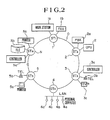
- Fig. 2 shows an example of the construction of a ring network system to which the invention is applied.
- various connected devices 1a to Nc are distributed at various places around a building (e.g., a factory, building or campus) are respectively associated with a network system through transmission equipment 1 to N thereby effecting the transfer of information among themselves.
- the transmission equipment are connected by a bit-serial transmission line O in a ring form thereby forming a so-called ring network.
- the system shown is a multi-media integrated network and it is capable of transmitting traffic of different characteristics in a mixed form.
- the connected devices may be a FAX 1b, a PBX 2a, telephones 3b and 5b, a camera 3c and a monitor 5a.
- the contention for the right to transmit is effected by use of the multiple access technique and then the transfer of information is made in burst form.
- the corresponding connected devices may then be a work station 1a, a computer 2b, controllers 3a and Na, a branch local area network, a file Nb and a printer Nc.
- a transmission line O includes a plurality of transmission channels (in the embodiment the number of channels is 3, i.e., C1, C2 and C3), each of transmission equipment 1 to 6 effects the reception of information through a certain fixed transmission channel and also effects the transmission of information by selecting the receiving transmission channel of associated one of the transmission equipment.
- the present invention has the effect of increasing the overall transmission capacity of the network system on the whole while limiting the transmission capacity of each transmission equipment to the band corresponding to each transmission channel.
- time division multiplexing wavelength multiplexing or space multiplexing may be used, and there is no particular limitation to the degree of multiplexing or the number of channels.
- the channel selection during transmission is effected by detecting the proper receiving channel of the destination transmission equipment.
- the present case shows that channel 1 is assigned for receiving purposes to the transmission equipment 1 and 4, channel 2 to the transmission equipment 2 and 5 and channel 3 to the transmission equipment 3 and 6. If, for example, the transmission equipment 1 is to transmit information to the transmission equipment 4, the channel 1 can be used to transmit, but if the information is to be transmitted to the transmission equipment 3 it must contend for the sending right on the channel 3.
- Fig. 3 is a block diagram showing the hardware of the transmission equipment for the ring network. Here, it is assumed that all the transmission equipment are identical in construction, that the transmission line is the single system type and that the multiplexing method is time division multiplexing. The following functional blocks are used.
- a unit for converting the signal on the transmission line in digital form which may perform various functions such as photo/electric conversion, signal amplification, timing extraction, or digital regeneration and decoding.
- a unit for converting digital information to a transmission line signal and transmitting it to the receiving unit which performs such functions as coding, signal drive and electric/photo conversion.
- This unit separates the multiplexed information for the plurality of transmission channels. It also serves such functions as frame synchronization detection and interchannel phase adjustment.
- this unit multiplexes the plurality of transmission channels for conversion into a single high-speed information string.
- This unit has various functions such as frame pattern generation, ring circulation delay time adjustment and deletion and regeneration of false circulation cells for the purpose of forming an STDM (synchronous time division multiplexing) frame.
- these functions are performed only in one of the transmission equipment and are not performed in the other transmission equipment thus allowing information to simply bypass.
- This unit performs information switching between the plurality of transmission channels forming the transmission line and the sending and receiving channels used between the transmission equipment and the devices connected thereto.
- This unit performs bus control processing such that the transmission channel selected by the channel switch unit is shared by a plurality of access interface unit.
- it has a subcommunication channel forming function for intra-network management and network structure control purposes and a communication function.
- This unit includes the respective parallel buses for receiving data, transmitting data, various timing and control signals, and microprocessor interfacing.
- the access controls to the transmission channels are roughly divided into two types (packet control and circuit control) in dependence on the type of traffic of information.
- the former performs the burst transmission and the latter performs the perioidic transmission.
- the serial receiving signal is converted to a digital signal by the receiving unit I1 and the signal is divided into the plurality of transmission channels and supplied to the channel switch unit I6 by the demultiplexing unit I6.
- the channel switch unit I6 forms a single receiving transmission channel and sends it to the bus control unit I7.
- the bus control unit I7 outputs its input to the transmission bus unit I8 so that it is received by the access interface units I01 to I 0m in the transmission equipment.
- the plurality of transmission channel information input to the channel switch unit I6 are sent to the multiplexing unit I4 via the frame control unit I5 so that after multiplexing, the information is sent to the transmission line O by the transmitting unit I2 and then transferred to the downstream-side transmission equipment.
- the transmitting information output to the transmission bus unit I8 is sent through the bus control unit I7 to the channel switch unit I6 which in turn transfers the information to the suitable place of the plurality of transmission channels.
- the information present in the transfer position is prevented from passing through the present transmission equipment and thus it is lost.
- the subsequent information path is as described previously.
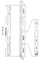
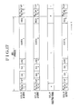
- Fig. 4 shows an example of the format of a multiplexing transmission frame and the format used is based on the NNI (network node interface) which is now investigated for use in the wideband ISDN (integrated services digital network) by the CCITT.
- the multiplexing on the transmission line O is effected in terms of bits or bytes and the frame length is 125 ⁇ sec. While, in this case, the degree of multiplexing is indicated as 4 by way of example, there is no limitation from the system point of view.
- each of transmission channels CH1 to CH4 has the same format and includes a plurality of time slots of the same length.
- each time slot includes a slot header and a plurality of cells of the same length.
- the header is used as a subcommunication channel for the purpose of frame synchronization as well as the previously mentioned intra-network management and network construction control.
- the transmission of information is effected by a portion of the cells so that in the case of the burst transmission, packet information is divided into the cells and is transmitted.
- packet information is divided into the cells and is transmitted.
- the periodic transmission there is no need to be conscious of the transmission in terms of cells, it is designed to conform with the burst transmission for purposes of simplicity.
- Fig. 5 shows an example of a transmission region allocation for the packet and the circuit information in each of the transmission channels CH1 to CH4.
- the limiting condition is that the same allocation must be used for the transmission channels requiring the interchange of information therebetween.
- the allocation is such that the frame is divided into the two areas with the cell or slot position as the boundary, it may be of another form in which the two areas are mixed together in terms of cells. Also, though not shown, two of the channels are entirely used for packet transmission purposes and the remaining two are used for circuit transmission purposes. Of course, a mixed type of such channels is also possible.
- While all the cells may be of the same format, in this case the cells of the two areas are of different forms so that the circuit cells are each composed of data only and the packet cells each requires header information in addition to data.
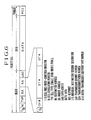
- Fig. 6 shows an example of a transmission format of the packet cells.
- the packet information is usually divided into a plurality of cells and transferred over the transmission line.
- each transmission channel is shared by the plurality of transmission equipment thus requiring an overhead for the purpose of multiple access in addition to a data area (DATA) which stores the packet information itself.
- DATA data area
- the address information SA has the following structure.
- Fig. 7 is a block diagram showing the hardware of the frame control unit I5.
- the frame generation, the ring circulation delay time adjustment, the false circulation cell detection, the initialization, etc., are performed and the blocks in the Figure perform the following functions.
- Each buffer includes mainly a two-port memory and makes an adjustment such that the ring circulating time of a signal becomes a given integral multiple of the frame length.
- the initial patterns of a frame and cells are generated.
- the phases of the transmission channels are synchronized and the patterns are used in common by all the channels.
- each ring delay buffer I52 The stored amount of transmission information in each ring delay buffer I52 is adjusted. In addition, the presence of any false circulation cell in each of the channels is checked so that if any, it is initialized.
- one of the transmission equipment of the network starts operating as a master and a transmission frame is transmitted by its pattern generating circuit I53. This function part in each of the other transmission equipment is stopped and is conditioned to pass the transmission frame. Thereafter, upon completion of the formation of the transmission frame, the selectors I51 select the ring delay buffer outputs excluding the necessary portion thereby starting the transfer of information of the respective transmission equipment.
- Fig. 8 shows a summary of the operation flow of the frame control unit I5. The operation of the frame control unit I5 will be described in greater detail with reference to the Figure.
- Fig. 9 is a block diagram showing the hardware of the bus control unit I7 in which the transmission channel from the channel switch unit I6 is converted to a structure which can be accessed by the plurality of access interface units I01 to I 0m in the transmission equipment.
- the necessary communication for the network management and the network structure control is performed by the internal processor.
- transmission buses I8 are incorporated. These buses are classified into the following four types.
- the receive-only bus which simultaneously transmits information to all the access interface units.
- the sending-only bus and one of the access interface units is given the right to use it to send information.
- This bus controls such signals including various timing signals for informing the access interface units with the frame and cell positions, signals for transmission contention among the access interface units and resending request signals to the access interface units from the channel switch unit.
- This bus allows the interchange of information between the microprocessor and the peripheral devices.
- the respective blocks serve the following functions.
- This circuit includes mainly a microprocessor and peripheral LSIs and it enables the transfer of information between it and other function units. For instance, it performs the transmission of available area information on a transmission frame to the circuit access interface units through the processor bus and so on.
- This communication subchannel is provided by a subchannel inserting and eliminating circuit I72.
- a certain band in the slot header area of the transmission frame is assigned to the communication subchannel between the processing circuits and this circuit performs the operation of delivering the information of this area to the processing circuit and receiving the information conversely.
- This circuit extracts the various transmission timing signals for the frame, cells, etc., from the receiving channel and supplies the signals to the access interface units.
- Fig. 10 is a block diagram showing the hardware of the access interface units I10. Each unit performs the interfacing between the connected device and the transmission equipment and it also performs the transmission and reception of information through the transmission channels.
- the respective blocks serve the following functions.
- This circuit performs the transfer of information between the transmission equipment and the connected device.
- the type of interfacing and the control method differ with the different connected devices.
- This circuit performs such communication processes as the buffer management, error control, flow control and sequential control. This function part is eliminated depending on the connected device.
- This circuit sends the communication information from the upper protocol processing circuit upon obtaining the right to send. Conversely, it serves the access control function of taking in the information on the transmission channel which is addressed thereto and transferring the information to the upper protocol processing circuit.
- the access methods are classified into two types, i.e., packet access method and circuit access method.
- the access method for packet information includes a slot process, token passing process, etc., and in this case the slot access process is employed as shown in Fig. 6.
- the method of preliminarily assigning fixed positions on a periodic transmission frame as transmission areas to each access interface unit e.g., FA-TDMA (fixed assignment-time division multiple access) for the circuit information.
- This circuit performs the transfer of network management information for the above-mentioned function parts.
- the network management information include various fault information, operation mode settings, various transmission parameters, etc. Also, the interchange of these management information between this and other transmission equipment is also possible and the information are transferred through the processor bus, the processing circuit and the subcommunication channel.
- This circuit supplies transmission timing signals to the respective function parts and also performs the transfer of transmission control signals through the control bus.
- the former includes such timing signals as the frame, cell, byte and bit clocks and the latter include such signals as the data transmission mode indicator, packet access interface contention signal and retransmission request signal.
- Fig. 11 is a flow chart showing the receiving access process for packet information.
- the destination address part DA is checked with respect to each of the cells in the packet area to check whether it is addressed to the transmission equipment in question. Then, the contents of the cells directed thereto are copied and taken in and also the receiving status is written in the answer area LA in case of need.
- Fig. 12 is a flow chart showing the transmitting access process for packet information.
- Fig. 13 is a flow chart showing the access operation for circuit information.
- the positions and amount of transmission are designated by the network management circuit I11, these positions are detected in the circuit area of the normal frame and the transmission and reception of data are performed.
- the transmitting and receiving positions may be either the same or different from each other.
- Fig. 14 is a block diagram showing the hardware of the channel switch unit I6 and it effects the interchange of information between the transmission channels CH1 to CH4. It includes the following function blocks.
- These circuits perform the passing information delaying operation required for the selecting operation of the transmitting selectors I61. This is due to the fact that the transmission of information for the access interface unit (I10) requires to delay the signal and the amount of delay is the same as that of the signal delay.
- This circuit generates selecting signals (SIi) for the receiving selectors and a selecting signal (SIR) for the receiving selector.
- the plurality of transmission channel information from the demultiplexing unit I3 are supplied to the receiving selector I63 and also to the sending selectors I61 through the delay circuits I62.
- the receiving selector I63 selects the information corresponding to the assigned receiving transmission channel and outputs it to the receiving data bus (RDB) of the transmission bus unit I8.
- RDB receiving data bus
- Fig. 15 is a block diagram showing the hardware of the switch control circuit I64.
- the method of information interchange between the transmission channels differs depending on whether it is a packet or circuit information and therefore the blocks of this circuit include two systems of hardware in mixed form. The functions of these blocks are as follows.
- the supply source of the sending selector (I61) selecting signals SIi is switched from one to the other.
- One is a packet switching control circuit I643 and the other is a circuit switching control circuit I647.
- the supply source of the receiving selector (I63) selecting signal SIR is switched from one to the other as in the case of 1).
- One is the packet switching control circuit I643 and the other is a receiving channel number register I646.
- This register stores the number of the transmission channel preselected to be used permanently for information receiving purposes. While the preselection is effected by a network management server, it is effected more directly by the processing circuit I71 of the bus control unit I7 through the control bus CTB of the transmission bus unit I8.
- This register temporarily stores the number of the transmission channel to which the destination transmission equipment is connected for packet transmitting purposes.
- this circuit detects the transmission channel to which the destination transmission equipment is connected.
- the access interface unit occupies the transmission bus unit I8 until the transmission of all the divided cells is completed properly and therefore the present circuit is required only to detect and inform the packet switching control circuit I643 of the fact that the first packet cell transmission has been started. In addition, its value is stored in the transmitting channel number storage register.
- This circuit controls the inter-channel switching of the packet information cells. More specifically, the transmission channel to be connected to is determined according to the destination of the packet cells sent from the intra-transmission equipment access interface unit and selecting signals SIR and SIi for the receiving selector I63 and the sending selectors I61, respectively, are generated.
- the sending-packet-leading-cell-number-detection signal from the channel-number-detecting circuit included among those signals which are input and output from the function blocks.
- the contents of the receiving-channel-number-register and the transmitting-channel-number-storage register included among those signals which are input and output from the function blocks.
- the busy-condition signals SND from the sending access interface units and the resending request signals RSR to the same units (these signals are both transferred through the control bus CTB of the transmission bus unit), etc.
- the transmission timing signals from the control bus CTB are received to generate the signals SIR and SIi only for the packet region established in the frame.
- This circuit performs the switching control required for sending the circuit information transmitted from the intra-transmission equipment access interface units to the transmission channel connected to the access interface units of the destination transmission equipment. Note that the destination channel information is preliminarily stored in this circuit. Its preset path is from the network management server to the present circuit through the intra-transmission equipment processing circuit and the processor bus MCB of the transmission bus unit.
- Fig. 16 is a flow chart showing the operation of the previously mentioned packet switching circuit.
- the channel number detecting circuit I644 After the number of receiving channels NC in the construction of this network system has been stored initially, it is waited until the channel number detecting circuit I644 reports the detection of the leading cell of the packet transmitted from the intra-transmission equipment access interface unit.
- the channel number detecting circuit I644 always checks the destination address of the packet shown in Fig. 6. It is designed so that when this cell is free, all-zero information (null address) is for example written into the destination address part and thus the presence of any other value indicates the existence of the transmitting information. Also, whether the packet cells are those sent from the transmission equipment in question can be similarly determined by checking the transmission equipment number of alternatively it is possible to detect the busy-condition signal SND in the control bus CTB. Assuming that the latter method is used in this case, particularly worthy of notice are the individual address/general address part I/G and the transmission channel number CH#.
- the transmitting channel number storage register I645 is the channel number used in the preceding transmission and presently the acquisition of the sending right is looked for by this channel. Therefore, if the two are equal, it is only necessary to just continue the transmission and complete it. If the two are not equal, the channel is changed and the retransmission of the packet is effected.
- the change of the channel is effected by setting the transmission channel number CH# in the transmitting packet cell in the transmitting channel number storage register. Once started, the transmission may be continued to the end or it may be interrupted on the way.
- the retransmission of the packet is effected by sending a resending request signal RSR to the presently transmitting access interface unit through the control bus CTB.
- the transmitting method upon the detection of the unequality in addition to the present embodiment, it is conceivable to use for example the method of storing all the packet information sent so that the switching to the proper channel is effected by the channel switch unit CSW thereby effecting the retransmission.
- the information in question is sent in sequence by the contention of the transmission right for the transmission channels thereby transferring it to all the transmission equipment.
- the transmission is started from the channel stored in the transmitting channel number storage register I645 and a request for the retransmission of the information is made to the corresponding access interface units by the resending request signals RSR.
- Fig. 17 is a packet cell reception switching time chart of the packet switching control circuit I643.
- the packet switching control circuit I643 controls the receiving selector I63 and the sending selectors I61 through the selectors I642 and I641, respectively.
- the switching operations of the various blocks of the channel switch unit I6 will now be described in detail.
- the first pattern indicates the receiving data of the transmission channel 1, the second pattern the receiving data of the transmission channel 4, the third pattern the selecting signal SIR to the receiving selector I63 and the last pattern the output of the receiving selector I63 or the receiving data to the access interface units via the receiving data bus RDB.
- the channel information corresponding to the content 4 of the transmitting channel number storage register are selected for the areas of the cell free/busy-condition indicator F/B, the cell circulation monitor M and the response RES and the channel information corresponding to the content 1 of the receiving channel number register are selected for the other areas.
- the information of the cell free/busy-condition indicator F/B and the cell circulation monitor M must be detected and transmitted by the access interface unit receiving a request for packet transmission and the information of the response RES must be transmitted by the access interface unit designated for reception.
- the information of the other areas must be received by the access interface units designated for reception.
- the transmitting and receiving equipment are completely separated with respect to the areas used and there is the merit of eliminating the need to provide separate information receiving and transmitting channels but combining the two in one by multiplexing.
- the need to confirm the source address SA can be eliminated by means of storing the positions of the cells used or the like.
- Fig. 18 is a transmission switching time chart of the packet cells on the transmission channel of the same number as the reception by the packet switching control circuit I643.
- the first pattern represents the A-side input information of the sending selector I611 in Fig. 14. This pattern shows the through information of the transmission channel 1. Then, the second pattern is the B-side input information of the transmission selector I611 and it represents the transmitting information from the transmitting information from the sending data bus SDB in the transmission bus unit I8.
- the third pattern is the selecting signal SS1 of the present selector and the fourth pattern is the output of the same selector. In these patterns, the horizontal axis direction shows the elapsed time.
- this selector operates in such a manner that the A-side inputs or the channel-1 through information is selected for the areas other than the response area RES and the B-side transmitting information is selected for the response area RES.
- sending selectors I612 and I613 are not required to receive information so that the A-side inputs are selected for all the areas to simply pass the information therethrough.
- Fig. 19 is a transmission switching time chart of the packet cells on the transmission channel equal to the transmission channel number by the packet switching control circuit I643.
- the first pattern shows the A-side input of the sending selector I614 or the through information of the transmission channel 4.
- the next pattern is the B-side input of the sending selector I614 or the transmitting information from the transmitting data bus SDB.
- the third pattern is the selecting signal SS4 of this selector, and the last pattern shows the output of this selector.
- this sending selector operates in such a manner that when the present transmission equipment transmits information, it always selects the B-side input or the transmitting information from the present transmission equipment.
- the previously mentioned busy-condition signal SND on the control bus CTB determines whether the present transmission equipment is sending information. It is to be noted that when there is no transmission of information from the transmission equipment, the present selector always operates so as to pass the A-side input or the information taken in from the receiving unit I1.
- Fig. 20 is a diagram combining the above-mentioned controls of the various parts to explain the packet cell switching operation and the channel switch unit I6, the sending data bus SDB and the receiving data bus RDB of the transmission bus unit I8 and the access interface unit I10 are shown typically.
- the Figure shows a case where the number of channels is 4 and both of the receiving channel number or the content of the receiving channel number register I646 and the transmitting channel number or the content of the transmitting channel number storage register I645 are 1.
- the information at various locations show the packet cell and its contents are divided broadly into three areas: i) the cell free/busy-condition indicator F/B and the cell circulation monitor M, ii) the response RES and iii) the other areas.
- i) is indicated by a symbol a
- ii) is indicated by a symbol a
- ii) is indicated by a
- ii) is indicated by a symbol a
- ii) by c and iii) by b Let it be assumed that these contents are designated by (a, b, c).
- the input cell of the transmission channel 1 is (a, b, c) and the input cell of the transmission channel 4 is (d, e, f).
- the output of the receiving selector I63 or the corresponding cell on the receiving data bus RDB becomes (a, b, c).
- the output of the sending selector I611 becomes (a, b, c) and the output of the sending selector I614 becomes (d, e, f), thereby passing these cells through the present transmission equipment.
- the access interface unit I10 has transmitting information and the input cell (a, b, c) of the transmission channel 1 is a free cell
- information (h, i, j) is outputted to the sending data bus SDR and the output of the sending selector I611 becomes (h, i, j).
- the other channels are the same as previously and the passage of informance is simply performed. This case is indicated by attaching parentheses at the corresponding cell position.
- the access interface unit I10 receives the input cell (a, b, c)
- only the answer area j is sent and thus the output of the sending selector I611 becomes (a, b, j).
- Fig. 21 is a diagram useful for explaining the switching operation of a packet cell and the illustrated case differs from the preceding case in that the content of the transmitting channel number storage register I645 is 4 and the content of the receiving channel number register I646 is 1.
- the output of the receiving selector I63 becomes (d, b, f) representing a mixed form of the information of the transmission channels 1 and 4.
- the presence of information directed to the present transmission equipment is always checked by the informance b and the presence of a free slot in the channel 4 is simultaneously checked by the information d .
- the Figure shows the operation performed during the reception of information so that each of the sending selectors 1611, 1612, I613 and I614 selects the A-side input or through information and the input and output patterns of each transmission channel become the same.
- Fig. 22 is a diagram useful for explaining the switching operation of a packet cell and the Figure shows a case where the transmission of information is effected under the same conditions as the previous case.
- the access interface unit I10 sends a cell pattern (h, i, j) to the sending data bus SDB.
- the content of the information d is judged thus sending data
- the transmission of data or the transmission of the free cells is effected in accordance with the cell position information stored during the transmission.
- the information sent onto the sending data bus SDB is outputted to the transmission channel 4 via the sending selector I614.
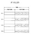
- Fig. 23 is an allocation diagram showing the inter-frame transmission areas for circuit information. Differing from the previously explained packet information, the positions of a transmission frame where each access interface unit performs the reception and transmission are fixed by setting. From the Figure it will be seen that in the case of circuit information, the transfer of information is also possible not only between the different parts of the same transmission channel but also between the different transmission channels. More specifically, the receiving transmission channel of each transmission equipment is fixed so that in the case of the transmission equipment using any other transmission channel, the transfer of the information between the channels is effected at the sending end.
- each access interface unit It is only necessary for each access interface unit to periodically effect the transmission and reception by using predetermined frame positions and information length (transmission rate).
- Fig. 24 is a function block diagram of the circuit switching control circuit I647. This circuit generates selecting signals SIi for the sending selectors I61 for the circuit information areas set in the frame. As regards a selecting signal SIR for the sending selector I63, the content of the receiving channel number register (I646) is permanently used as shown in Fig. 15. The function parts are as follows.
- the setting is effected by storing what are transferred to the circuit from the processing circuit I71 through the processor bus MCB. During the operation, the addressing is effected in response to a counter I6473. The content read is sent to a selector control pattern generating circuit I6471. The memory content is settable for each byte in the frame.
- This counter supplies address information to the circuit access memory I6472.
- the counter In response to the transmission timing signals from the control bus CTB, the counter counts up for every byte.
- This circuit has a decoding function to change the selecting pattern coded and stored in the circuit access memory to a sending selector selecting signal.
- Fig. 25 shows an example of a time chart for the circuit information switching operation.
- the time chart shows an example of the operation of a certain transmission equipment to which the transmission channel 1 is assigned for receiving purposes.
- the first pattern shows the receiving data of the channel 1
- the second pattern the selecting signal SIR of the receiving selector I63
- third and following patterns the selecting signals S1, S2, S3 and S4 of the sending selectors I61.
- the transmission and reception of information within the transmission channel 1 are effected at a frame position T1.
- the transmitting information is sent into the channel 2 and the transmission channel 1 receives the information addressed to itself from the access interface unit assigned to the transmission channel 2.
- Fig. 26 is a block diagram for explaining the switching operation of circuit information and it integrates the previously mentioned controls of the various parts. While the hardware elements are the same as in the case of Fig. 20, the information shown at the various part indicate the circuit area information in the transmission frame. The information are broadly divided into the following four parts.
- First area (e.g., a in the Figure)
- This area is assigned for the transfer of information within the transmission channel 1 and it is also used by the present transmission equipment for the purpose of transmission and reception.
- Second area (e.g., b in the Figure)
- This area is assigned for the transfer of information within the transmission channel 1 but not by the present transmission equipment for transmitting and receiving purposes.
- This area is assigned for the transfer of information between the transmission channels 1 and 4 and this area is not used by the present transmission equipment for transmitting and receiving purposes.
- This area is assigned for the transfer of information between the transmission channels 1 and 4 and it is also used by the present transmission equipment for the transmission and reception.
- the packet areas and the transmission areas between the other channels will not be explained for purposes of simplicity.
- the receiving transmission channel is permanently set to the channel 1 and therefore the output of the receiving selector I63 or the information (a, b, c, d) on the receiving data bus RDB appears as such. Also, the transmission of information from the present transmission equipment is effected as i at the position corresponding to a and as j at the position corresponding to d as shown on the sending data bus SDB.
- the sending selector I611 performs the transmission of the first area only and thus its output becomes (i, b, c, d). Also, the sending selector I614 performs the transmission of the fourth area only and thus its output becomes (e, f, g, j). With the other channels, their input information are passed as such.
- Fig. 27 is a block diagram showing the hardware construction of the channel switch unit I6 used when realizing the circuit information switching by another method.
- This construction differs from Fig. 14 in that a spatial switch I65 is inserted before the receiving selector I63.
- This circuit is capable of interchanging information between the transmission channels and this is utilized for the transfer of circuit information between the channels.
- the switch control circuit I64 which controls the receiving selector I63 and the sending selectors I61, it is only necessary to deal with the packet information only.
- the spatial switch operation is usually effected collectively only within the single transmission equipment in the network.
- ATM asynchronous transfer mode
- Fig. 28 is a diagram for explaining the operation of the spatial switch circuit for the interchanging of information between the channels.
- the upper rows show a spatial switch input and the lower rows show its output.
- the method of allocating the areas within the circuit region is the same as in Fig. 23. Therefore, the information in the areas A, E, I and M are assigned for the transfer of information within the transmission channel and thus no information interchanging takes place. In the other areas, however, the following interchanging of information is effected.
- Fig. 29 is a block diagram showing an example of the hardware construction of a transmission equipment increased in transmission capacity.
- the single channel switch unit I6 is included in each transmission equipment. This limits the transmission capacity accessible by each transmission equipment to that which corresponds to one transmission channel at the most. Thus, in the case of high-speed equipment or where a large number of equipment are gathered, there is possibility of the transmission capacity becoming insufficient. While this deficiency can be overcome by the method of arranging the transmission equipment in cascade, not only a number of expensive transmitting and receiving units are required but also the number of relay stages is increased, thereby increasing the deterioration in transmission quality.
- a transmission equipment is constructed so that transmitting and receiving units I1 and I2, multiplexing and demultiplexing units I3 and I4 and a frame control unit I5 are used in common, and channel switch units I6 and the following are connected in cascade.
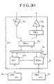
- Fig. 30 shows the hardware construction of each transmission equipment used in a case where the number of transmission channels is 1. It is convenient to construct the transmission equipment by the building block system which clearly divides its component parts into those which are dependent on the transmission line speed and others which are not so thereby allowing it to meet a variety of needs. A description will be made of the necessary changes due to the change of application from the previously mentioned system using the plurality of transmission channels to a system using a single transmission channel.
- a transmission equipment I L with a transmission line including a single transmission channel transmitting and receiving units I 1L and I 2L , a frame control unit I 5L and a bus control unit I 7L must be changed.
- the other function units are used as such as previously.
- the transmitting and receiving units operate at a lower speed than in the case of Fig. 3.
- the frame control unit corresponds to a case where the number of channels is 1 as compared with the case of Fig. 7.
- the bus control unit requires the addition of a control for the passage of information between the sending and receiving data buses to the construction of Fig. 9.
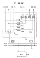
- Fig. 31 shows the hardware construction of the bus control unit I 7L in the transmission equipment having the transmission line including the single transmission channel.
- an element I 7L4 and an element I 7L5 respectively corresponding to the delay circuits and the sending selectors of Fig. 14 are added to provide an information passing path from the receiving data bus RDB to the sending data bus SDB.
- the control of the selector I 7L5 is effected through the control bus CTB by the access interface unit which transmit information so that it operates so as to bypass the information on the sending data bus SDB in the presence of transmitting information and to bypass the receiving information in the reverse case.
- Fig. 32 shows an example of a transmission format used in a case employing a token passing method for the access control of packet information.
- a format is used which is based on the FDDI (fider distributed data interface) under standard investigation by the X3T9.5 Committee of ANSI.
- FDDI carrier distributed data interface
- a free token which is information denoting a ready for sending is circulated through the ring transmission line so that any of the access interface units detecting and acquiring the free token is allowed to transmit packet information which is called a frame.
- the free token information is regenerated and also the packet information sent from the present equipment is eliminated after it has rounded the ring.
- FCS Frame check sequence
- token passing is performed in a network including a plurality of transmission channels
- token information for each channel so that during packet transmission, the transmission is effected after the sending right on the transmission channel to which the destination transmission equipment is connected is obtained. Since all the information directed to this equipment are transferred over the initially assigned transmission channel, it is only necessary to permanently search this channel for information receiving purposes. The switching timing of the transmitting channels must be made upon completion of the ring rounding and deletion of the originating frame.
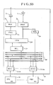
- Fig. 33 shows the hardware construction of a transmission equipment employing the token passing for the access control of packet information. Differing from the previously mentioned slot access method, an information receiving channel and a channel on which a free token is searched for information transmitting purposes cannot be combined in one by multiplexing and therefore two separate receiving channels are required.
- This transmission equipment differs in this respect from the construction of Fig. 3 and there is added a selector I9 for selecting one of a plurality of receiving channels from a demultiplexing unit I3 or the one assigned for reception. Also, two separate receiving data buses RDB1 and RDB2 must correspondingly provided in place of the receiving data bus RDB and also the respective access interface units are changed correspondingly.
- the access interface unit performs the token access processing (hold/release of transmission right by token) in response to the data from the bus RDB2 in the destination channel. Note that there is no change with respect to the processing of circuit information and it is performed as mentioned previously.
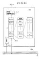
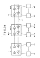
- Fig. 34 shows the system construction of a network in the form of a bus (open ring).
- the transmission operation is performed in such a manner that the transmission equipment at one end generates a transmission frame and the transmission equipment at the other end returns it.
- the transmission equipment arranged intermediary between the two transmit information over the down circuit and receive information over the up circuit.
- the packet access control used may take the form of a slot taken passing, it is necessary to use two systems of receiving transmission channels as in the case explained in connection with Fig. 33.
- Fig. 35 shows the hardware construction of transmission equipment used in the bus-type network.
- An exclusive up receiving transmission line is added to the construction shown in Fig. 3.
- transmitting and receiving units I 1B2 and I 2B2 there are additionally provided transmitting and receiving units I 1B2 and I 2B2 , a demultiplexing unit I 3B2 and a selector I9 which selects predetermined one of a plurality of receiving channels from the demultiplexing unit I 3B2 .
- a frame control circuit I 5B is required to have a pattern generating function only as mentioned previously.
Abstract
Description
- The present invention relates to a transmission system for a network including a plurality of transmission channels, and more particularly to a network system well suited for the respective transmission equipment to effect the interchange of information between arbitrarily selected ones of the transmission equipment through the channels.
- Transmission systems of this type have been discussed in the past in the program paper 1769 presented at the General National Convention of the Society of Electronic Communication, 1986, p 8 - 5 and the program paper 282 presented at the National Convention of the Information and System Department of the Society of Electronic Information Communication, 1987, p 2 - 13. Both of these propose to greatly increase the capacity of a network through the use of a transmission line including a plurality of low-speed transmission channels.
- With the above-mentioned conventional techniques, no consideration has been made for the compatibility of the transmission equipment with cases where the network includes the single transmission channel and where the network includes the plurality of transmission channels and therefore there is a disadvantage that the existing transmission equipment cannot be reused when the transmission capacity of the network is increased. The present invention aims to overcome this.
- The present invention means of increasing the transmission capacity of a network on the whole by using the transmission equipment each having a single transmission channel between it and the device connected thereto for the purpose.
- This may be accomplished by providing a transmission line including a plurality of channels, preliminarily assigning one of the receiving transmission channels to each of transmission equipment such that each of the channels has the equal traffic to effect the transmission and reception of information and enabling the transfer of the transmitting information to the receiving transmission channel assigned to the destination transmission equipment.
- Each of the transmission equipment is allowed not only to receive information through its previously assigned single transmission channel for receiving purposes but also to transfer information to any other transmission equipment having its separate assigned transmission channel for receiving purposes. As a result, even the known transmission equipment each having a single transmission channel between itself and various devices, is used, each of the transmission equipment can transfer its transmitting information to the receiving transmission channel assigned to the destination transmission equipment thereby increasing the transmission capacity of a network as a whole.
- Preferred embodiments of the present invention will now be described, by way of example, with reference to the accompanying drawings wherein:
- Fig. 1 is a diagram showing the concept of a transmission system representing a feature of the present invention.
- Fig. 2 is a diagram showing the construction of a ring network system.
- Fig. 3 is a block diagram showing the hardware of the ring network transmission equipment.
- Fig. 4 shows the format of a multiplexing transmission frame.
- Fig. 5 is a diagram showing the allocation of the transmission channels.
- Fig. 6 shows a transmission format of the packet region cell.
- Fig. 7 is a block diagram showing the hardware of the frame control unit.
- Fig. 8 is a flow diagram showing the operation of the frame control circuit.
- Fig. 9 is a block diagram showing the hardware of the bus control unit.
- Fig. 10 is a block diagram showing the hardware of the access interface unit.
- Fig. 11 is a receiving access flow for packet information.
- Fig. 12 is a transmitting access flow for packet information.
- Fig. 13 is an access flow for circuit information.
- Fig. 14 is a block diagram showing the hardware of the channel switching unit.
- Fig. 15 is a block diagram showing the hardware of the switch control circuit.
- Fig. 16 is a flow diagram showing the operation of the packet switching control circuit.
- Figs. 17, 18 and 19 are packet cell switching timing charts.
- Figs. 20, 21 and 22 are diagrams useful for explaining the switching operations of packet cells.
- Fig. 23 is an allocation diagram showing the transmitting areas in the circuit information frame.
- Fig. 24 is a functional block diagram of the circuit switching control circuit.
- Fig. 25 is a time chart of the circuit information switching operation.
- Fig. 26 is a diagram useful for explaining the circuit information switching operation.
- Fig. 27 is a diagram showing the hardware construction of a channel switching unit used when realizing the circuit information switching by another embodiment.
- Fig. 28 is a diagram useful for explaining the operation of the spatial switch circuit.
- Fig. 29 is a diagram showing the hardware construction of transmission equipment used for increasing the transmission capacity.
- Fig. 30 is a diagram showing the hardware construction of transmission equipment when the number of transmission channel is 1.
- Fig. 31 is a block diagram showing the hardware of the bus control unit when the number of transmission channels is 1.
- Fig. 32 shows a transmission format in the token pass control.
- Fig. 33 is a diagram showing the hardware construction of transmission equipment employing the token passing control.
- Fig. 34 is a system block diagram of the bus-type network.
- Fig. 35 is a block diagram showing the hardware of transmission equipment in the bus-type network.
- Fig. 2 shows an example of the construction of a ring network system to which the invention is applied. As shown in the Figure, various connected devices 1a to Nc are distributed at various places around a building (e.g., a factory, building or campus) are respectively associated with a network system through
transmission equipment 1 to N thereby effecting the transfer of information among themselves. In this case, the transmission equipment are connected by a bit-serial transmission line O in a ring form thereby forming a so-called ring network. - The system shown is a multi-media integrated network and it is capable of transmitting traffic of different characteristics in a mixed form. For instance, in the transmission of sound and picture media requiring long retension times and short transmission delay times, the transfer of information is effected periodically by using predetermined fixed transmission areas. The connected devices may be a FAX 1b, a
PBX 2a,telephones 3b and 5b, acamera 3c and amonitor 5a. Also, for the transmission of data media requiring short retension times and subjected to loss restrictions in transmission delay time, the contention for the right to transmit is effected by use of the multiple access technique and then the transfer of information is made in burst form. The corresponding connected devices, may then be a work station 1a, a computer 2b,controllers 3a and Na, a branch local area network, a file Nb and a printer Nc. - With this type of network system, progress has been made toward enhancing the connected devices in performance and function and increasing the network scale and there has existed a demand for networks system which are higher in speed and greater in capacity than previously.
- Referring now to Fig. 1, there is shown a transmission system having the features of the present invention. A transmission line O includes a plurality of transmission channels ( in the embodiment the number of channels is 3, i.e., C₁, C₂ and C₃), each of
transmission equipment 1 to 6 effects the reception of information through a certain fixed transmission channel and also effects the transmission of information by selecting the receiving transmission channel of associated one of the transmission equipment. - From the Figure it will be seen that the present invention has the effect of increasing the overall transmission capacity of the network system on the whole while limiting the transmission capacity of each transmission equipment to the band corresponding to each transmission channel.
- As the multiplexing method for forming the plurality of transmission channels C₁, C₂ and C₃, time division multiplexing, wavelength multiplexing or space multiplexing may be used, and there is no particular limitation to the degree of multiplexing or the number of channels.
- The channel selection during transmission is effected by detecting the proper receiving channel of the destination transmission equipment. The present case shows that
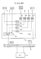
channel 1 is assigned for receiving purposes to thetransmission equipment channel 2 to thetransmission equipment channel 3 to thetransmission equipment 3 and 6. If, for example, thetransmission equipment 1 is to transmit information to thetransmission equipment 4, thechannel 1 can be used to transmit, but if the information is to be transmitted to thetransmission equipment 3 it must contend for the sending right on thechannel 3. - Fig. 3 is a block diagram showing the hardware of the transmission equipment for the ring network. Here, it is assumed that all the transmission equipment are identical in construction, that the transmission line is the single system type and that the multiplexing method is time division multiplexing. The following functional blocks are used.
- A unit for converting the signal on the transmission line in digital form which may perform various functions such as photo/electric conversion, signal amplification, timing extraction, or digital regeneration and decoding.
- A unit for converting digital information to a transmission line signal and transmitting it to the receiving unit which performs such functions as coding, signal drive and electric/photo conversion.
- This unit separates the multiplexed information for the plurality of transmission channels. It also serves such functions as frame synchronization detection and interchannel phase adjustment.
- Contrary in function to the demultiplexing unit, this unit multiplexes the plurality of transmission channels for conversion into a single high-speed information string.
- This unit has various functions such as frame pattern generation, ring circulation delay time adjustment and deletion and regeneration of false circulation cells for the purpose of forming an STDM (synchronous time division multiplexing) frame. In the network, these functions are performed only in one of the transmission equipment and are not performed in the other transmission equipment thus allowing information to simply bypass.
- This unit performs information switching between the plurality of transmission channels forming the transmission line and the sending and receiving channels used between the transmission equipment and the devices connected thereto.
- This unit performs bus control processing such that the transmission channel selected by the channel switch unit is shared by a plurality of access interface unit. In addition, it has a subcommunication channel forming function for intra-network management and network structure control purposes and a communication function.
- This unit includes the respective parallel buses for receiving data, transmitting data, various timing and control signals, and microprocessor interfacing.
- These units perform interfacing between the connected devices and the transmission equipment to effect the transmission and reception of information. The access controls to the transmission channels are roughly divided into two types (packet control and circuit control) in dependence on the type of traffic of information. The former performs the burst transmission and the latter performs the perioidic transmission.
- The basic information flow inside the
transmission equipment 1 will now be described. The serial receiving signal is converted to a digital signal by the receiving unit I₁ and the signal is divided into the plurality of transmission channels and supplied to the channel switch unit I₆ by the demultiplexing unit I₆. The channel switch unit I₆ forms a single receiving transmission channel and sends it to the bus control unit I₇. The bus control unit I₇ outputs its input to the transmission bus unit I₈ so that it is received by the access interface units I₀₁ to I0m in the transmission equipment. When there is no transmission of information from these access interface units, the plurality of transmission channel information input to the channel switch unit I₆ are sent to the multiplexing unit I₄ via the frame control unit I₅ so that after multiplexing, the information is sent to the transmission line O by the transmitting unit I₂ and then transferred to the downstream-side transmission equipment. Alternatively, when any information is transmitted from the access interface units I₀₁ to I0m, the transmitting information output to the transmission bus unit I₈ is sent through the bus control unit I₇ to the channel switch unit I₆ which in turn transfers the information to the suitable place of the plurality of transmission channels. At this tine, of the input information from the demultiplexing unit I₃, the information present in the transfer position is prevented from passing through the present transmission equipment and thus it is lost. The subsequent information path is as described previously. - Fig. 4 shows an example of the format of a multiplexing transmission frame and the format used is based on the NNI (network node interface) which is now investigated for use in the wideband ISDN (integrated services digital network) by the CCITT. The multiplexing on the transmission line O is effected in terms of bits or bytes and the frame length is 125 µsec. While, in this case, the degree of multiplexing is indicated as 4 by way of example, there is no limitation from the system point of view.
- After the separation, each of transmission channels CH₁ to CH₄ has the same format and includes a plurality of time slots of the same length.
- Also, each time slot includes a slot header and a plurality of cells of the same length. The header is used as a subcommunication channel for the purpose of frame synchronization as well as the previously mentioned intra-network management and network construction control. The transmission of information is effected by a portion of the cells so that in the case of the burst transmission, packet information is divided into the cells and is transmitted. On the other hand, while, in the case of the periodic transmission, there is no need to be conscious of the transmission in terms of cells, it is designed to conform with the burst transmission for purposes of simplicity.
- Fig. 5 shows an example of a transmission region allocation for the packet and the circuit information in each of the transmission channels CH₁ to CH₄. In this case, the limiting condition is that the same allocation must be used for the transmission channels requiring the interchange of information therebetween.
- While the allocation is such that the frame is divided into the two areas with the cell or slot position as the boundary, it may be of another form in which the two areas are mixed together in terms of cells. Also, though not shown, two of the channels are entirely used for packet transmission purposes and the remaining two are used for circuit transmission purposes. Of course, a mixed type of such channels is also possible.
- While all the cells may be of the same format, in this case the cells of the two areas are of different forms so that the circuit cells are each composed of data only and the packet cells each requires header information in addition to data.
- Fig. 6 shows an example of a transmission format of the packet cells. The packet information is usually divided into a plurality of cells and transferred over the transmission line. However, each transmission channel is shared by the plurality of transmission equipment thus requiring an overhead for the purpose of multiple access in addition to a data area (DATA) which stores the packet information itself. This information is composed of the following.
- 1) F/B: Indicates the free/busy-condition of the cell in question.
- 2) M: This is the information for monitoring the false circulation of the cells through the ring.
- 3) TYP: Indicates the type of the cell when the packet is resolved into the cells. There are four types: "single", "head", "middle" and "final".
- 4) DA: The address information indicating the destination access interface unit.
- 5) SA: The address information indicating the source access interface unit.
- 6) LNG: Indicates the packet length and distinguishes the effective data portion in the cell.
- 7) RES: The response information from the destination access interface unit to the source.
- Here, the address information SA has the following structure.
- i) I/G: Distinction of the individual/general addresses.
- ii) CH#: The number of the transmission channel used for the reception
- iii) ST#: The number of the transmission station.
- iv) UT#: The number of the access interface unit in the transmission equipment.
- By using such hierarchical address information, the selection of the destination transmission channel during the sending of packet information can be effected easily.
- Fig. 7 is a block diagram showing the hardware of the frame control unit I₅. The frame generation, the ring circulation delay time adjustment, the false circulation cell detection, the initialization, etc., are performed and the blocks in the Figure perform the following functions.
- Either the frame information from a pattern generating circuit I₅₃ or the frame information from a ring delay buffer I₅₂ is selected and supplied to the multiplexing unit I₄ by each selector.
- Each buffer includes mainly a two-port memory and makes an adjustment such that the ring circulating time of a signal becomes a given integral multiple of the frame length.
- The initial patterns of a frame and cells are generated. The phases of the transmission channels are synchronized and the patterns are used in common by all the channels.
- The stored amount of transmission information in each ring delay buffer I₅₂ is adjusted. In addition, the presence of any false circulation cell in each of the channels is checked so that if any, it is initialized.
- During the initial period of the system, one of the transmission equipment of the network starts operating as a master and a transmission frame is transmitted by its pattern generating circuit I₅₃. This function part in each of the other transmission equipment is stopped and is conditioned to pass the transmission frame. Thereafter, upon completion of the formation of the transmission frame, the selectors I₅₁ select the ring delay buffer outputs excluding the necessary portion thereby starting the transfer of information of the respective transmission equipment.
- Fig. 8 shows a summary of the operation flow of the frame control unit I₅. The operation of the frame control unit I₅ will be described in greater detail with reference to the Figure.
- i) During the initial period, in any one of the
transmission equipment 1 to N which is selected as a master, the selectors I₅₁ of the frame control unit I₅ select the initial transmission frame information output generated from the pattern generating circuit I₅₃. (The A-side inputs are selected.) - ii) Thereafter, the information goes round the ring and appears at the inputs of the ring delay buffers I₅₂. However, the information is not taken into the buffers.
- iii) After the frame synchronization has been established, the circulated information is applied to the ring delay buffer starting at the head. Since the outputs from the buffers are locked, the received information is stored up in the buffers.
- iv) In this condition, when the transmission of the transmission frame from the pattern generating circuit is completed, the generation of the information from the ring delay buffers is simultaneously effected so that the selectors are conditioned to select the B-side inputs for the subsequent cell information to complete the transmission frame formation, thus starting the transfer of information from the respective transmission equipment.
- v) Thereafter, the detection of false circulation cells is performed by the M information explained in connection with Fig. 6 and also a check for the presence of frame synchronization is effected.
- Fig. 9 is a block diagram showing the hardware of the bus control unit I₇ in which the transmission channel from the channel switch unit I₆ is converted to a structure which can be accessed by the plurality of access interface units I₀₁ to I0m in the transmission equipment. In addition, the necessary communication for the network management and the network structure control is performed by the internal processor.
- To permit the accommodation of the plurality of access interface units I₀₁ to I0m in each of the
transmission equipment 1 to N, the illustrated transmission buses I₈ are incorporated. These buses are classified into the following four types. - The receive-only bus which simultaneously transmits information to all the access interface units.
- The sending-only bus and one of the access interface units is given the right to use it to send information.
- This bus controls such signals including various timing signals for informing the access interface units with the frame and cell positions, signals for transmission contention among the access interface units and resending request signals to the access interface units from the channel switch unit.
- This bus allows the interchange of information between the microprocessor and the peripheral devices. The respective blocks serve the following functions.
- This circuit includes mainly a microprocessor and peripheral LSIs and it enables the transfer of information between it and other function units. For instance, it performs the transmission of available area information on a transmission frame to the circuit access interface units through the processor bus and so on.
- On the other hand, communication with the processors in the other transmission equipment is required for the network management, the network structure control and so on. This communication subchannel is provided by a subchannel inserting and eliminating circuit I₇₂.
- A certain band in the slot header area of the transmission frame is assigned to the communication subchannel between the processing circuits and this circuit performs the operation of delivering the information of this area to the processing circuit and receiving the information conversely.
- This circuit extracts the various transmission timing signals for the frame, cells, etc., from the receiving channel and supplies the signals to the access interface units.
- Fig. 10 is a block diagram showing the hardware of the access interface units I₁₀. Each unit performs the interfacing between the connected device and the transmission equipment and it also performs the transmission and reception of information through the transmission channels. The respective blocks serve the following functions.
- This circuit performs the transfer of information between the transmission equipment and the connected device. The type of interfacing and the control method differ with the different connected devices.
- This circuit performs such communication processes as the buffer management, error control, flow control and sequential control. This function part is eliminated depending on the connected device.
- This circuit sends the communication information from the upper protocol processing circuit upon obtaining the right to send. Conversely, it serves the access control function of taking in the information on the transmission channel which is addressed thereto and transferring the information to the upper protocol processing circuit. In accordance with the traffic characteristics of transmission information to be handled, the access methods are classified into two types, i.e., packet access method and circuit access method. The access method for packet information includes a slot process, token passing process, etc., and in this case the slot access process is employed as shown in Fig. 6.
- On the other hand, the method of preliminarily assigning fixed positions on a periodic transmission frame as transmission areas to each access interface unit, e.g., FA-TDMA (fixed assignment-time division multiple access) for the circuit information.
- This circuit performs the transfer of network management information for the above-mentioned function parts. The network management information include various fault information, operation mode settings, various transmission parameters, etc. Also, the interchange of these management information between this and other transmission equipment is also possible and the information are transferred through the processor bus, the processing circuit and the subcommunication channel.
- This circuit supplies transmission timing signals to the respective function parts and also performs the transfer of transmission control signals through the control bus. The former includes such timing signals as the frame, cell, byte and bit clocks and the latter include such signals as the data transmission mode indicator, packet access interface contention signal and retransmission request signal.
- Fig. 11 is a flow chart showing the receiving access process for packet information. In the normal condition of the transmission frame, the destination address part DA is checked with respect to each of the cells in the packet area to check whether it is addressed to the transmission equipment in question. Then, the contents of the cells directed thereto are copied and taken in and also the receiving status is written in the answer area LA in case of need.
- Fig. 12 is a flow chart showing the transmitting access process for packet information. When a request to send is generated so that it is now ready to send, the detection of the free cells (F/B = F) in the packet area of the normal transmission frame and the originating cells rounding the ring is effected and the transmission of information is effected. Note that in the latter case, the response signal (RES) from the designated receiving-end is received simultaneously. When the transmission of information is completed, all of the originating cells rounding the ring are restored to the free state, thereby completing the sequence of operations.
- Fig. 13 is a flow chart showing the access operation for circuit information. When the positions and amount of transmission are designated by the network management circuit I₁₁, these positions are detected in the circuit area of the normal frame and the transmission and reception of data are performed. The transmitting and receiving positions may be either the same or different from each other.
- Fig. 14 is a block diagram showing the hardware of the channel switch unit I₆ and it effects the interchange of information between the transmission channels CH₁ to CH₄. It includes the following function blocks.
- This extracts the single receiving channel assigned to the
transmission equipment 1 from the plurality of transmission channels CH₁ to CH₄ and uses it for the information receiving or transmitting contention. - These are provided one for each of the transmission channels to perform the gate function of passing the information from the corresponding receiving channel or passing the information transmitted by the access interface unit I₁₀.
- These circuits perform the passing information delaying operation required for the selecting operation of the transmitting selectors I₆₁. This is due to the fact that the transmission of information for the access interface unit (I₁₀) requires to delay the signal and the amount of delay is the same as that of the signal delay.
- This circuit generates selecting signals (SIi) for the receiving selectors and a selecting signal (SIR) for the receiving selector.
- The plurality of transmission channel information from the demultiplexing unit I₃ are supplied to the receiving selector I₆₃ and also to the sending selectors I₆₁ through the delay circuits I₆₂. In response to the command from the switch control circuit I₆₄, the receiving selector I₆₃ selects the information corresponding to the assigned receiving transmission channel and outputs it to the receiving data bus (RDB) of the transmission bus unit I₈. It is to be noted that while there is in fact an intervention of the bus control unit I₇ this is not explained for purposes of simplification. Since it is arranged so that the information outputted from the sending data bus (SDB) is supplied to one input of each of the sending selectors, the information can be sent to any one of the transmission channels.
- Fig. 15 is a block diagram showing the hardware of the switch control circuit I₆₄. The method of information interchange between the transmission channels differs depending on whether it is a packet or circuit information and therefore the blocks of this circuit include two systems of hardware in mixed form. The functions of these blocks are as follows.
- In response to the timing of the packet or circuit cells preliminarily established in a given frame, the supply source of the sending selector (I₆₁) selecting signals SIi is switched from one to the other. One is a packet switching control circuit I₆₄₃ and the other is a circuit switching control circuit I₆₄₇.
- Depending on the packet or circuit cells, the supply source of the receiving selector (I₆₃) selecting signal SIR is switched from one to the other as in the case of 1). One is the packet switching control circuit I₆₄₃ and the other is a receiving channel number register I₆₄₆.
- This register stores the number of the transmission channel preselected to be used permanently for information receiving purposes. While the preselection is effected by a network management server, it is effected more directly by the processing circuit I₇₁ of the bus control unit I₇ through the control bus CTB of the transmission bus unit I₈.
- This register temporarily stores the number of the transmission channel to which the destination transmission equipment is connected for packet transmitting purposes.
- In accordance with the destination information DA of the packet cells, this circuit detects the transmission channel to which the destination transmission equipment is connected. During the packet transmission, the access interface unit occupies the transmission bus unit I₈ until the transmission of all the divided cells is completed properly and therefore the present circuit is required only to detect and inform the packet switching control circuit I₆₄₃ of the fact that the first packet cell transmission has been started. In addition, its value is stored in the transmitting channel number storage register.
- This circuit controls the inter-channel switching of the packet information cells. More specifically, the transmission channel to be connected to is determined according to the destination of the packet cells sent from the intra-transmission equipment access interface unit and selecting signals SIR and SIi for the receiving selector I₆₃ and the sending selectors I₆₁, respectively, are generated. In addition, included among those signals which are input and output from the function blocks are the sending-packet-leading-cell-number-detection signal from the channel-number-detecting circuit, the contents of the receiving-channel-number-register and the transmitting-channel-number-storage register, the busy-condition signals SND from the sending access interface units and the resending request signals RSR to the same units (these signals are both transferred through the control bus CTB of the transmission bus unit), etc. Also, the transmission timing signals from the control bus CTB are received to generate the signals SIR and SIi only for the packet region established in the frame.
- This circuit performs the switching control required for sending the circuit information transmitted from the intra-transmission equipment access interface units to the transmission channel connected to the access interface units of the destination transmission equipment. Note that the destination channel information is preliminarily stored in this circuit. Its preset path is from the network management server to the present circuit through the intra-transmission equipment processing circuit and the processor bus MCB of the transmission bus unit.
- Fig. 16 is a flow chart showing the operation of the previously mentioned packet switching circuit.
- After the number of receiving channels NC in the construction of this network system has been stored initially, it is waited until the channel number detecting circuit I₆₄₄ reports the detection of the leading cell of the packet transmitted from the intra-transmission equipment access interface unit. The channel number detecting circuit I₆₄₄ always checks the destination address of the packet shown in Fig. 6. It is designed so that when this cell is free, all-zero information (null address) is for example written into the destination address part and thus the presence of any other value indicates the existence of the transmitting information. Also, whether the packet cells are those sent from the transmission equipment in question can be similarly determined by checking the transmission equipment number of alternatively it is possible to detect the busy-condition signal SND in the control bus CTB. Assuming that the latter method is used in this case, particularly worthy of notice are the individual address/general address part I/G and the transmission channel number CH#.
- The processing to follow differs depending on whether the destination address is the individual destination or the general destination. Each of the two cases will now be described in detail.
- In the case of the individual destination I, it is confirmed whether there is the equality between the content stored in the transmitting channel number storage register I₆₄₅ and the number of the transmission channel requested by the current transmission. The content stored in the transmitting channel number storage register is the channel number used in the preceding transmission and presently the acquisition of the sending right is looked for by this channel. Therefore, if the two are equal, it is only necessary to just continue the transmission and complete it. If the two are not equal, the channel is changed and the retransmission of the packet is effected. The change of the channel is effected by setting the transmission channel number CH# in the transmitting packet cell in the transmitting channel number storage register. Once started, the transmission may be continued to the end or it may be interrupted on the way. The retransmission of the packet is effected by sending a resending request signal RSR to the presently transmitting access interface unit through the control bus CTB.
- As regards the transmitting method upon the detection of the unequality, in addition to the present embodiment, it is conceivable to use for example the method of storing all the packet information sent so that the switching to the proper channel is effected by the channel switch unit CSW thereby effecting the retransmission.
- A description will now be made of the case of the general transmission G where the destination address is directed to all the transmission equipment.
- With this embodiment, in the case of the general transmission G the information in question is sent in sequence by the contention of the transmission right for the transmission channels thereby transferring it to all the transmission equipment. By so doing, it is possible to reduce the complication of the controls, such as, the provision of a general transmission part in the packet area and the dynamic allocation of it along with the individual transmission part. In fact, the transmission is started from the channel stored in the transmitting channel number storage register I₆₄₅ and a request for the retransmission of the information is made to the corresponding access interface units by the resending request signals RSR.
- From the foregoing description it will be seen that it is so constructed that the access interface units I₁₀ secure the use right on the transmission bus unit I₈ until the transmission of the information is completed properly.
- Fig. 17 is a packet cell reception switching time chart of the packet switching control circuit I₆₄₃. The packet switching control circuit I₆₄₃ controls the receiving selector I₆₃ and the sending selectors I₆₁ through the selectors I₆₄₂ and I₆₄₁, respectively. The switching operations of the various blocks of the channel switch unit I₆ will now be described in detail.
- The description will be made with reference to a case in which the number of channels is set to 4, the receiving channel number of the present transmission equipment or the content of the receiving channel number register I₆₄₆ is set to 1 and the transmitting channel number or the content of the transmitting channel number storage register I₆₄₅ is set to 4. In the Figure, the first pattern indicates the receiving data of the
transmission channel 1, the second pattern the receiving data of thetransmission channel 4, the third pattern the selecting signal SIR to the receiving selector I₆₃ and the last pattern the output of the receiving selector I₆₃ or the receiving data to the access interface units via the receiving data bus RDB. - It will be seen that in the packet cell, the channel information corresponding to the
content 4 of the transmitting channel number storage register are selected for the areas of the cell free/busy-condition indicator F/B, the cell circulation monitor M and the response RES and the channel information corresponding to thecontent 1 of the receiving channel number register are selected for the other areas. In other words, the information of the cell free/busy-condition indicator F/B and the cell circulation monitor M must be detected and transmitted by the access interface unit receiving a request for packet transmission and the information of the response RES must be transmitted by the access interface unit designated for reception. Also, the information of the other areas must be received by the access interface units designated for reception. - Thus, in accordance with the slot access method the transmitting and receiving equipment are completely separated with respect to the areas used and there is the merit of eliminating the need to provide separate information receiving and transmitting channels but combining the two in one by multiplexing.
- During the reception, even if the cell free/busy-condition indicator F/B is not used, it is possible to introduce a null as the address of free cells so that it is only necessary to confirm the equality of the destination address. Also, as regards the deletion of the transmitted cells after rounding of the ring, the need to confirm the source address SA can be eliminated by means of storing the positions of the cells used or the like.
- Fig. 18 is a transmission switching time chart of the packet cells on the transmission channel of the same number as the reception by the packet switching control circuit I₆₄₃.
- In the Figure, the first pattern represents the A-side input information of the sending selector I₆₁₁ in Fig. 14. This pattern shows the through information of the
transmission channel 1. Then, the second pattern is the B-side input information of the transmission selector I₆₁₁ and it represents the transmitting information from the transmitting information from the sending data bus SDB in the transmission bus unit I₈. The third pattern is the selecting signal SS₁ of the present selector and the fourth pattern is the output of the same selector. In these patterns, the horizontal axis direction shows the elapsed time. - Thus, it will be seen that this selector operates in such a manner that the A-side inputs or the channel-1 through information is selected for the areas other than the response area RES and the B-side transmitting information is selected for the response area RES. This is due to the fact that the access interface units connected to the present transmission equipment are set to use the
transmission channel 1 for receiving purposes and therefore they are permitted to pass all the information other than that for the response area RES. - It is to be noted that the sending selectors I₆₁₂ and I₆₁₃ are not required to receive information so that the A-side inputs are selected for all the areas to simply pass the information therethrough.
- Fig. 19 is a transmission switching time chart of the packet cells on the transmission channel equal to the transmission channel number by the packet switching control circuit I₆₄₃.
- In the Figure, the first pattern shows the A-side input of the sending selector I₆₁₄ or the through information of the
transmission channel 4. The next pattern is the B-side input of the sending selector I₆₁₄ or the transmitting information from the transmitting data bus SDB. The third pattern is the selecting signal SS₄ of this selector, and the last pattern shows the output of this selector. - Thus, it will be seen that this sending selector operates in such a manner that when the present transmission equipment transmits information, it always selects the B-side input or the transmitting information from the present transmission equipment. The previously mentioned busy-condition signal SND on the control bus CTB determines whether the present transmission equipment is sending information. It is to be noted that when there is no transmission of information from the transmission equipment, the present selector always operates so as to pass the A-side input or the information taken in from the receiving unit I₁.
- Fig. 20 is a diagram combining the above-mentioned controls of the various parts to explain the packet cell switching operation and the channel switch unit I₆, the sending data bus SDB and the receiving data bus RDB of the transmission bus unit I₈ and the access interface unit I₁₀ are shown typically. The Figure shows a case where the number of channels is 4 and both of the receiving channel number or the content of the receiving channel number register I₆₄₆ and the transmitting channel number or the content of the transmitting channel number storage register I₆₄₅ are 1.
- Also, the information at various locations show the packet cell and its contents are divided broadly into three areas: i) the cell free/busy-condition indicator F/B and the cell circulation monitor M, ii) the response RES and iii) the other areas. For instance, in the
transmission channel 1, i) is indicated by a symbol a, ii) by c and iii) by b. Let it be assumed that these contents are designated by (a, b, c). - Assume that the input cell of the
transmission channel 1 is (a, b, c) and the input cell of thetransmission channel 4 is (d, e, f). The output of the receiving selector I₆₃ or the corresponding cell on the receiving data bus RDB becomes (a, b, c). - In this case, if these cells are not directed to the present transmission equipment and are thus ignored by its access interface unit I₁₀, the output of the sending selector I₆₁₁ becomes (a, b, c) and the output of the sending selector I₆₁₄ becomes (d, e, f), thereby passing these cells through the present transmission equipment. Although not shown, the same applies to the
transmission channels - Then, where the access interface unit I₁₀ has transmitting information and the input cell (a, b, c) of the
transmission channel 1 is a free cell, information (h, i, j) is outputted to the sending data bus SDR and the output of the sending selector I₆₁₁ becomes (h, i, j). The other channels are the same as previously and the passage of informance is simply performed. This case is indicated by attaching parentheses at the corresponding cell position. - Although not shown in the Figure, where the access interface unit I₁₀ receives the input cell (a, b, c), only the answer area j is sent and thus the output of the sending selector I₆₁₁ becomes (a, b, j).
- From the foregoing description it will be seen that when the receiving channel number and the transmitting channel number are the same, the access control on these channels can be performed in the same manner as the case where the number of channels is 1.
- Fig. 21 is a diagram useful for explaining the switching operation of a packet cell and the illustrated case differs from the preceding case in that the content of the transmitting channel number storage register I₆₄₅ is 4 and the content of the receiving channel number register I₆₄₆ is 1. In this case, the output of the receiving selector I₆₃ becomes (d, b, f) representing a mixed form of the information of the
transmission channels channel 4 is simultaneously checked by the information d. - The Figure shows the operation performed during the reception of information so that each of the sending
selectors - Notes that only when the access interface unit I₁₀ has transmitted answer information g, only the output of the sending selector I₆₁₁ changes from (a, b, c) to (a, b, g).
- Fig. 22 is a diagram useful for explaining the switching operation of a packet cell and the Figure shows a case where the transmission of information is effected under the same conditions as the previous case.
- When the input cell of the
transmission channel 4 is free or in the case of the originating cell rounding the ring, the access interface unit I₁₀ sends a cell pattern (h, i, j) to the sending data bus SDB. In the former case, the content of the information d is judged thus sending data, whereas in the latter case, the transmission of data or the transmission of the free cells is effected in accordance with the cell position information stored during the transmission. The information sent onto the sending data bus SDB is outputted to thetransmission channel 4 via the sending selector I₆₁₄. - Fig. 23 is an allocation diagram showing the inter-frame transmission areas for circuit information. Differing from the previously explained packet information, the positions of a transmission frame where each access interface unit performs the reception and transmission are fixed by setting. From the Figure it will be seen that in the case of circuit information, the transfer of information is also possible not only between the different parts of the same transmission channel but also between the different transmission channels. More specifically, the receiving transmission channel of each transmission equipment is fixed so that in the case of the transmission equipment using any other transmission channel, the transfer of the information between the channels is effected at the sending end.
- It is only necessary for each access interface unit to periodically effect the transmission and reception by using predetermined frame positions and information length (transmission rate).
- Fig. 24 is a function block diagram of the circuit switching control circuit I₆₄₇. This circuit generates selecting signals SIi for the sending selectors I₆₁ for the circuit information areas set in the frame. As regards a selecting signal SIR for the sending selector I₆₃, the content of the receiving channel number register (I₆₄₆) is permanently used as shown in Fig. 15. The function parts are as follows.
- This is a two-port memory which stores a sending selector selecting signal SIi pattern in correspondence to each of the positions of a transmission frame. The setting is effected by storing what are transferred to the circuit from the processing circuit I₇₁ through the processor bus MCB. During the operation, the addressing is effected in response to a counter I₆₄₇₃. The content read is sent to a selector control pattern generating circuit I₆₄₇₁. The memory content is settable for each byte in the frame.
- This counter supplies address information to the circuit access memory I₆₄₇₂. In response to the transmission timing signals from the control bus CTB, the counter counts up for every byte.
- This circuit has a decoding function to change the selecting pattern coded and stored in the circuit access memory to a sending selector selecting signal.
- Fig. 25 shows an example of a time chart for the circuit information switching operation. The time chart shows an example of the operation of a certain transmission equipment to which the
transmission channel 1 is assigned for receiving purposes. In the Figure, the first pattern shows the receiving data of thechannel 1, the second pattern the selecting signal SIR of the receiving selector I₆₃, and third and following patterns the selecting signals S₁, S₂, S₃ and S₄ of the sending selectors I₆₁. - The transmission and reception of information within the
transmission channel 1 are effected at a frame position T₁. At a frame position T₂, the transmitting information is sent into thechannel 2 and thetransmission channel 1 receives the information addressed to itself from the access interface unit assigned to thetransmission channel 2. - Then, the similar operations are performed at frame positions T₃, T₄ and T₅. It will be seen that the transfer of circuit information between the different transmission channels can be realized in this way by using the same channel switch unit I₆ as used for the transfer of the packet information.
- Fig. 26 is a block diagram for explaining the switching operation of circuit information and it integrates the previously mentioned controls of the various parts. While the hardware elements are the same as in the case of Fig. 20, the information shown at the various part indicate the circuit area information in the transmission frame. The information are broadly divided into the following four parts.
- This area is assigned for the transfer of information within the
transmission channel 1 and it is also used by the present transmission equipment for the purpose of transmission and reception. - This area is assigned for the transfer of information within the
transmission channel 1 but not by the present transmission equipment for transmitting and receiving purposes. - This area is assigned for the transfer of information between the
transmission channels - This area is assigned for the transfer of information between the
transmission channels - With the present transmission equipment, the receiving transmission channel is permanently set to the
channel 1 and therefore the output of the receiving selector I₆₃ or the information (a, b, c, d) on the receiving data bus RDB appears as such. Also, the transmission of information from the present transmission equipment is effected as i at the position corresponding to a and as j at the position corresponding to d as shown on the sending data bus SDB. - The sending selector I₆₁₁ performs the transmission of the first area only and thus its output becomes (i, b, c, d). Also, the sending selector I₆₁₄ performs the transmission of the fourth area only and thus its output becomes (e, f, g, j). With the other channels, their input information are passed as such.
- Fig. 27 is a block diagram showing the hardware construction of the channel switch unit I₆ used when realizing the circuit information switching by another method. This construction differs from Fig. 14 in that a spatial switch I₆₅ is inserted before the receiving selector I₆₃. This circuit is capable of interchanging information between the transmission channels and this is utilized for the transfer of circuit information between the channels. As a result, in the case of the switch control circuit I₆₄ which controls the receiving selector I₆₃ and the sending selectors I₆₁, it is only necessary to deal with the packet information only. Also, the spatial switch operation is usually effected collectively only within the single transmission equipment in the network. While there are various types of spatial switches, one type of these switches is the ATM (asynchronous transfer mode) switch which is used for cell interchanging purposes in the wideband ISDN (integrated services digital network) and this can be used for the purpose. In this case, the interchange is effected for every cell and the interchange operation is effected on the basis of the address information in the cells.
- Fig. 28 is a diagram for explaining the operation of the spatial switch circuit for the interchanging of information between the channels. In the Figure, the upper rows show a spatial switch input and the lower rows show its output.
- The method of allocating the areas within the circuit region is the same as in Fig. 23. Therefore, the information in the areas A, E, I and M are assigned for the transfer of information within the transmission channel and thus no information interchanging takes place. In the other areas, however, the following interchanging of information is effected.
- i) Between the
channels - ii) Between the
channels - iii) Between the
channels - iv) Between the
channels - v) Between the
channels - vi) Between the
channels - Fig. 29 is a block diagram showing an example of the hardware construction of a transmission equipment increased in transmission capacity. In the embodiment described so far by way of example, the single channel switch unit I₆ is included in each transmission equipment. This limits the transmission capacity accessible by each transmission equipment to that which corresponds to one transmission channel at the most. Thus, in the case of high-speed equipment or where a large number of equipment are gathered, there is possibility of the transmission capacity becoming insufficient. While this deficiency can be overcome by the method of arranging the transmission equipment in cascade, not only a number of expensive transmitting and receiving units are required but also the number of relay stages is increased, thereby increasing the deterioration in transmission quality.
- Thus, as shown in the Figure, a transmission equipment is constructed so that transmitting and receiving units I₁ and I₂, multiplexing and demultiplexing units I₃ and I₄ and a frame control unit I₅ are used in common, and channel switch units I₆ and the following are connected in cascade. By virtue of this construction, the transmission capacity accessible from each transmission equipment can be used up to the capacity of the transmission line without increasing the number of relay stages.
- Fig. 30 shows the hardware construction of each transmission equipment used in a case where the number of transmission channels is 1. It is convenient to construct the transmission equipment by the building block system which clearly divides its component parts into those which are dependent on the transmission line speed and others which are not so thereby allowing it to meet a variety of needs. A description will be made of the necessary changes due to the change of application from the previously mentioned system using the plurality of transmission channels to a system using a single transmission channel.
- In a transmission equipment IL with a transmission line including a single transmission channel, transmitting and receiving units I1L and I2L, a frame control unit I5L and a bus control unit I7L must be changed. The other function units are used as such as previously. The transmitting and receiving units operate at a lower speed than in the case of Fig. 3. The frame control unit corresponds to a case where the number of channels is 1 as compared with the case of Fig. 7. The bus control unit requires the addition of a control for the passage of information between the sending and receiving data buses to the construction of Fig. 9.
- Fig. 31 shows the hardware construction of the bus control unit I7L in the transmission equipment having the transmission line including the single transmission channel. In addition to the function parts shown in Fig. 9, an element I7L4 and an element I7L5 respectively corresponding to the delay circuits and the sending selectors of Fig. 14 are added to provide an information passing path from the receiving data bus RDB to the sending data bus SDB. The control of the selector I7L5 is effected through the control bus CTB by the access interface unit which transmit information so that it operates so as to bypass the information on the sending data bus SDB in the presence of transmitting information and to bypass the receiving information in the reverse case.
- Fig. 32 shows an example of a transmission format used in a case employing a token passing method for the access control of packet information. A format is used which is based on the FDDI (fider distributed data interface) under standard investigation by the X3T9.5 Committee of ANSI. Differing from the previously described slot access method, a free token which is information denoting a ready for sending is circulated through the ring transmission line so that any of the access interface units detecting and acquiring the free token is allowed to transmit packet information which is called a frame. Immediately after the completion of the transmission, the free token information is regenerated and also the packet information sent from the present equipment is eliminated after it has rounded the ring.
- The detailed definitions of the respective information are as follows.
- This is arranged at the head of information to correct the bit synchronization at the receiving end.
- This indicates the starting position of information.
- This indicates the end position of information. Different patterns are used for the token and the frame.
- This indicates the type of frame information.
- This is used for identifying the destination transmission equipment of frame information.
- This is used for identifying the source transmission equipment of frame information.
- An error detecting addition code for frame information.
- An area provided for the purpose of informing various receiving statuses from the receiving transmission equipment.
- Where the token passing is performed in a network including a plurality of transmission channels, there exists token information for each channel so that during packet transmission, the transmission is effected after the sending right on the transmission channel to which the destination transmission equipment is connected is obtained. Since all the information directed to this equipment are transferred over the initially assigned transmission channel, it is only necessary to permanently search this channel for information receiving purposes. The switching timing of the transmitting channels must be made upon completion of the ring rounding and deletion of the originating frame.
- Fig. 33 shows the hardware construction of a transmission equipment employing the token passing for the access control of packet information. Differing from the previously mentioned slot access method, an information receiving channel and a channel on which a free token is searched for information transmitting purposes cannot be combined in one by multiplexing and therefore two separate receiving channels are required. This transmission equipment differs in this respect from the construction of Fig. 3 and there is added a selector I₉ for selecting one of a plurality of receiving channels from a demultiplexing unit I₃ or the one assigned for reception. Also, two separate receiving data buses RDB₁ and RDB₂ must correspondingly provided in place of the receiving data bus RDB and also the respective access interface units are changed correspondingly. In other words, in addition to the receiving processing performed in response to the data from the bus RDB₁, the access interface unit performs the token access processing (hold/release of transmission right by token) in response to the data from the bus RDB₂ in the destination channel. Note that there is no change with respect to the processing of circuit information and it is performed as mentioned previously.
- Fig. 34 shows the system construction of a network in the form of a bus (open ring). In this form, the transmission operation is performed in such a manner that the transmission equipment at one end generates a transmission frame and the transmission equipment at the other end returns it. The transmission equipment arranged intermediary between the two transmit information over the down circuit and receive information over the up circuit. As a result, while two or up and down systems of transmitting and receiving units are required despite the single system network, there is the effect of eliminating such functions as the rounding delay control of the ring transmission line and the rounding and elimination of transmitting information. While the packet access control used may take the form of a slot taken passing, it is necessary to use two systems of receiving transmission channels as in the case explained in connection with Fig. 33.
- Fig. 35 shows the hardware construction of transmission equipment used in the bus-type network. An exclusive up receiving transmission line is added to the construction shown in Fig. 3. In other words, there are additionally provided transmitting and receiving units I1B2 and I2B2, a demultiplexing unit I3B2 and a selector I₉ which selects predetermined one of a plurality of receiving channels from the demultiplexing unit I3B2. As in the case of Fig. 33, it is necessary to provide two systems of receiving data buses and access interface receiving units, respectively. It is to be noted that a frame control circuit I5B is required to have a pattern generating function only as mentioned previously.
Claims (16)
a transmission line (0) including a plurality of transmission channels (C₁-C₄);
a plurality of transmission equipment (1-N) connected to said transmission line (0) to transmit and receive information from each other;
a plurality of devices (1a, 1b, 2a, 2b, 3a-3c, 4a-4d, 5a-5b, Na-Nc) connected to each of said transmission equipment (1-N) to effect transfer of information between said devices connected to said plurality of transmission equipment,
each of said transmission equipment (1-N) including:
a demultiplexing unit (I₃) for separating an input signal from said transmission line (0) into a plurality of receiving transmission channels (C₁, C₂, C₃);
at least one channel switch unit (I₆) for receiving the plurality of receiving transmission channels (C₁-C₄), outputting selected one of said plurality of separated transmission channels (C₁-C₄) to one of said devices (1a, 1b, 2a, 2b, 3a-3c, 4a-4d, 5a-5b, Na-Nc connected to each said transmission equipment (1-N), and receiving transmitting information from said one device to form an information sending channel and combining the same with other channels to be passed to form a plurality of sending transmission channels (C₁-C₄); and
a multiplexing unit (I₄) for receiving the plurality of sending transmission channels (C₁-C₄) from said channel switch unit (I₆) and multiplexing said plurality of sending transmission channels (C₁-C₄) to generate an output.
Applications Claiming Priority (2)
| Application Number | Priority Date | Filing Date | Title |
|---|---|---|---|
| JP63287701A JPH0695677B2 (en) | 1988-11-16 | 1988-11-16 | Network transmission system with multiple channels |
| JP287701/88 | 1988-11-16 |
Publications (2)
| Publication Number | Publication Date |
|---|---|
| EP0369802A2 true EP0369802A2 (en) | 1990-05-23 |
| EP0369802A3 EP0369802A3 (en) | 1991-11-27 |
Family
ID=17720622
Family Applications (1)
| Application Number | Title | Priority Date | Filing Date |
|---|---|---|---|
| EP19890311903 Withdrawn EP0369802A3 (en) | 1988-11-16 | 1989-11-16 | Network system |
Country Status (3)
| Country | Link |
|---|---|
| US (1) | US5497370A (en) |
| EP (1) | EP0369802A3 (en) |
| JP (1) | JPH0695677B2 (en) |
Cited By (3)
| Publication number | Priority date | Publication date | Assignee | Title |
|---|---|---|---|---|
| EP0472296A1 (en) * | 1990-08-02 | 1992-02-26 | AT&T Corp. | High-performance packet-switched wdm ring networks with tunable lasers |
| WO1998027690A1 (en) * | 1996-12-16 | 1998-06-25 | Samsung Electronics Co. Ltd. | Method for sending e-mail messages in a local area network, and device for applying same |
| EP0717522A3 (en) * | 1994-12-16 | 1998-09-09 | Canon Kabushiki Kaisha | Communication network with plural optical channels, node and concentrator for use therein |
Families Citing this family (12)
| Publication number | Priority date | Publication date | Assignee | Title |
|---|---|---|---|---|
| JP3340738B2 (en) * | 1991-10-04 | 2002-11-05 | ベイ ネットワークス インコーポレイテッド | Method and apparatus for a parallel packet bus |
| JPH08265349A (en) * | 1995-03-27 | 1996-10-11 | Toshiba Microelectron Corp | Digital information processor |
| US5706278A (en) * | 1995-07-20 | 1998-01-06 | Raytheon Company | Deterministic network protocol |
| AT410875B (en) * | 1996-01-10 | 2003-08-25 | Frequentis Nachrichtentechnik Gmbh | METHOD AND SYSTEM FOR TRANSMITTING DATA |
| JP3251537B2 (en) * | 1997-06-16 | 2002-01-28 | 矢崎総業株式会社 | Communication method and communication system |
| US6154462A (en) | 1997-08-21 | 2000-11-28 | Adc Telecommunications, Inc. | Circuits and methods for a ring network |
| US6331985B1 (en) * | 1997-08-21 | 2001-12-18 | Adc Telecommunications, Inc. | Telecommunication network with variable address learning, switching and routing |
| US6570880B1 (en) | 1998-08-21 | 2003-05-27 | Adc Telecommunications, Inc. | Control data over a ring network |
| US6539546B1 (en) | 1998-08-21 | 2003-03-25 | Adc Telecommunications, Inc. | Transport of digitized signals over a ring network |
| US6389030B1 (en) | 1998-08-21 | 2002-05-14 | Adc Telecommunications, Inc. | Internet access over a ring network |
| US7139791B1 (en) * | 2000-07-13 | 2006-11-21 | International Business Machines Corporation | Apparatus and method for providing access to a data stream by a plurality of users at a same time |
| KR100628822B1 (en) * | 2000-07-14 | 2006-09-27 | 인터내셔널 비지네스 머신즈 코포레이션 | Communication control method and device |
Citations (1)
| Publication number | Priority date | Publication date | Assignee | Title |
|---|---|---|---|---|
| US4370744A (en) * | 1979-03-02 | 1983-01-25 | Nippon Telegraph & Telephone Public Corp. | Time division multiplex communication system |
Family Cites Families (13)
| Publication number | Priority date | Publication date | Assignee | Title |
|---|---|---|---|---|
| US4445214A (en) * | 1980-05-30 | 1984-04-24 | Harris Corporation | Method of controlling message transmission sequence in multi station communication system |
| JPS57111166A (en) * | 1980-12-26 | 1982-07-10 | Fujitsu Ltd | Add-on connection system |
| JPS5980041A (en) * | 1982-10-29 | 1984-05-09 | Natl Aerospace Lab | Digital multiplex optical coupling controller for installation on airplane |
| US4637013A (en) * | 1983-07-05 | 1987-01-13 | Canon Kabushiki Kaisha | Token exchange data transmission system having system configuration discrimination |
| US4608685A (en) * | 1984-04-30 | 1986-08-26 | Northern Telecom Limited | Packet and circuit switched communications network |
| JPS6194433A (en) * | 1984-10-15 | 1986-05-13 | Mitsubishi Electric Corp | Control system for serial bus |
| JPS61174851A (en) * | 1985-01-30 | 1986-08-06 | Agency Of Ind Science & Technol | Bus control system |
| US4740956A (en) * | 1985-12-30 | 1988-04-26 | Ibm Corporation | Linear-space signalling for a circuit-switched network |
| US4698802A (en) * | 1986-03-07 | 1987-10-06 | American Telephone And Telegraph Company And At&T Information Systems Inc. | Combined circuit and packet switching system |
| DE3875139D1 (en) * | 1987-03-09 | 1992-11-12 | Siemens Ag | CIRCUIT ARRANGEMENT FOR SUBSCRIBER CONNECTION CIRCUITS OF A DIGITAL TIME MULTIPLEX TELECOMMUNICATION SWITCH. |
| US4942573A (en) * | 1987-03-25 | 1990-07-17 | Unisys Corporation | Loosely coupled parallel network simulator |
| US4852091A (en) * | 1988-04-21 | 1989-07-25 | Bell Communications Research, Inc. | High capacity communication system utilizing OR-type channels |
| US4897841A (en) * | 1989-01-11 | 1990-01-30 | Hughes Lan Systems, Inc. | System and method for bridging local area networks using concurrent broadband channels |
-
1988
- 1988-11-16 JP JP63287701A patent/JPH0695677B2/en not_active Expired - Lifetime
-
1989
- 1989-11-16 EP EP19890311903 patent/EP0369802A3/en not_active Withdrawn
-
1994
- 1994-02-16 US US08/197,535 patent/US5497370A/en not_active Expired - Fee Related
Patent Citations (1)
| Publication number | Priority date | Publication date | Assignee | Title |
|---|---|---|---|---|
| US4370744A (en) * | 1979-03-02 | 1983-01-25 | Nippon Telegraph & Telephone Public Corp. | Time division multiplex communication system |
Non-Patent Citations (3)
| Title |
|---|
| GLOBECOM'82 vol. 3, December 1982, NEW YORK US pages 949 - 955; C. TSENG ET AL.: 'D-Net. A new scheme for high data rate optical local area networks ' * |
| GLOBECOM'85 VOL. 3; DEC. 1985; NEW YORK US; K. OHNO ET AL.: "MULTIPURPOSE OPTICAL LOOP NETWORK" PAGES 34.6.1-34.6.6 * |
| GLOBECOM'87 vol. 3, November 1987, NEW YORK US pages 1449 - 1454; N.FUJIMOTO ET AL.: 'BROADBAND SUBSCRIBER LOOP SYSTEM USING MULTI-GIGABIT INTELLIGENT OPTICAL SHUTTLE NODES ' * |
Cited By (5)
| Publication number | Priority date | Publication date | Assignee | Title |
|---|---|---|---|---|
| EP0472296A1 (en) * | 1990-08-02 | 1992-02-26 | AT&T Corp. | High-performance packet-switched wdm ring networks with tunable lasers |
| EP0717522A3 (en) * | 1994-12-16 | 1998-09-09 | Canon Kabushiki Kaisha | Communication network with plural optical channels, node and concentrator for use therein |
| US6078415A (en) * | 1994-12-16 | 2000-06-20 | Canon Kabushiki Kaisha | Network system for communication with plural channels, node device and concentrator for use therein, and communication method for said network system |
| WO1998027690A1 (en) * | 1996-12-16 | 1998-06-25 | Samsung Electronics Co. Ltd. | Method for sending e-mail messages in a local area network, and device for applying same |
| US6219714B1 (en) | 1996-12-16 | 2001-04-17 | Samsung Electronics Co., Ltd. | Method for sending e-mail messages in a local area network, and device for applying same |
Also Published As
| Publication number | Publication date |
|---|---|
| JPH02135833A (en) | 1990-05-24 |
| US5497370A (en) | 1996-03-05 |
| JPH0695677B2 (en) | 1994-11-24 |
| EP0369802A3 (en) | 1991-11-27 |
Similar Documents
| Publication | Publication Date | Title |
|---|---|---|
| JP2615297B2 (en) | Ring communication system | |
| EP0369802A2 (en) | Network system | |
| EP0462349B1 (en) | Broadband ring communication system and access control method | |
| JPH02291745A (en) | Format converter | |
| JPH0629992A (en) | Data transmission method and network used for it | |
| JPH08288981A (en) | Line changeover system for duplex transmitter between different modes | |
| JP2001223704A (en) | Packet transfer device | |
| JPH0720122B2 (en) | Packet communication system using ring type transmission line | |
| JP2600596B2 (en) | Cross connect device | |
| US5612958A (en) | Method and device for the asynchronous transmission of data by means of a synchronous bus | |
| JPH05167549A (en) | Control information transmission system for time division multiplex communication system | |
| US6466546B1 (en) | Communication apparatus for multiplexing and communicating a plurality of types of data, communication system, and control method therefor | |
| US5768265A (en) | Duplex signal multiplexing system | |
| JPS62261250A (en) | Mechanism for facilitating exchange of data and non-encoded information in communication network | |
| JP2979504B2 (en) | Interface device for ATM network | |
| US6298040B1 (en) | Data link layer processor system for a local exchange system | |
| JP2846464B2 (en) | Data switching node | |
| JPH089058A (en) | Multiplexer with transmission line backup function | |
| JP3586520B2 (en) | Digital message relay system | |
| JP2655487B2 (en) | Multiplexing system | |
| JPH07327053A (en) | Multiplexer, repeater and line concentrator | |
| JPH08221289A (en) | Control system for duplex system | |
| JPH02276339A (en) | High-speed ring lan system and lan node | |
| JPH11220473A (en) | Data transmission system | |
| JPH10276214A (en) | Asynchronous transfer mode switch |
Legal Events
| Date | Code | Title | Description |
|---|---|---|---|
| PUAI | Public reference made under article 153(3) epc to a published international application that has entered the european phase |
Free format text: ORIGINAL CODE: 0009012 |
|
| 17P | Request for examination filed |
Effective date: 19900115 |
|
| AK | Designated contracting states |
Kind code of ref document: A2 Designated state(s): DE FR GB |
|
| PUAL | Search report despatched |
Free format text: ORIGINAL CODE: 0009013 |
|
| AK | Designated contracting states |
Kind code of ref document: A3 Designated state(s): DE FR GB |
|
| 17Q | First examination report despatched |
Effective date: 19940713 |
|
| STAA | Information on the status of an ep patent application or granted ep patent |
Free format text: STATUS: THE APPLICATION IS DEEMED TO BE WITHDRAWN |
|
| 18D | Application deemed to be withdrawn |
Effective date: 19951228 |