EP0373823A2 - Surgical fastener cartridge with improved body tissue cutting knife assembly - Google Patents
Surgical fastener cartridge with improved body tissue cutting knife assembly Download PDFInfo
- Publication number
- EP0373823A2 EP0373823A2 EP89312707A EP89312707A EP0373823A2 EP 0373823 A2 EP0373823 A2 EP 0373823A2 EP 89312707 A EP89312707 A EP 89312707A EP 89312707 A EP89312707 A EP 89312707A EP 0373823 A2 EP0373823 A2 EP 0373823A2
- Authority
- EP
- European Patent Office
- Prior art keywords
- knife
- fastener cartridge
- fastener
- holder
- cartridge
- Prior art date
- Legal status (The legal status is an assumption and is not a legal conclusion. Google has not performed a legal analysis and makes no representation as to the accuracy of the status listed.)
- Ceased
Links
- 238000005520 cutting process Methods 0.000 title claims abstract description 25
- 230000002427 irreversible effect Effects 0.000 claims abstract description 6
- 229920001169 thermoplastic Polymers 0.000 claims description 8
- 239000004416 thermosoftening plastic Substances 0.000 claims description 8
- 229920000515 polycarbonate Polymers 0.000 claims description 5
- 239000004417 polycarbonate Substances 0.000 claims description 4
- 229920005992 thermoplastic resin Polymers 0.000 abstract 1
- 125000006850 spacer group Chemical group 0.000 description 7
- 238000005304 joining Methods 0.000 description 4
- 239000002184 metal Substances 0.000 description 4
- 238000000034 method Methods 0.000 description 3
- 238000001356 surgical procedure Methods 0.000 description 3
- 238000003466 welding Methods 0.000 description 3
- -1 e.g. Substances 0.000 description 2
- 238000010304 firing Methods 0.000 description 2
- 230000023597 hemostasis Effects 0.000 description 2
- 239000000463 material Substances 0.000 description 2
- 230000000717 retained effect Effects 0.000 description 2
- 229910001220 stainless steel Inorganic materials 0.000 description 2
- 239000010935 stainless steel Substances 0.000 description 2
- 229920004142 LEXAN™ Polymers 0.000 description 1
- 239000004418 Lexan Substances 0.000 description 1
- 239000004425 Makrolon Substances 0.000 description 1
- 239000000853 adhesive Substances 0.000 description 1
- 238000004026 adhesive bonding Methods 0.000 description 1
- 230000001070 adhesive effect Effects 0.000 description 1
- 230000000712 assembly Effects 0.000 description 1
- 238000000429 assembly Methods 0.000 description 1
- 210000000038 chest Anatomy 0.000 description 1
- 238000004140 cleaning Methods 0.000 description 1
- 238000010276 construction Methods 0.000 description 1
- 230000000694 effects Effects 0.000 description 1
- 238000003780 insertion Methods 0.000 description 1
- 230000037431 insertion Effects 0.000 description 1
- 210000000936 intestine Anatomy 0.000 description 1
- 238000004519 manufacturing process Methods 0.000 description 1
- 230000013011 mating Effects 0.000 description 1
- 238000012986 modification Methods 0.000 description 1
- 230000004048 modification Effects 0.000 description 1
- 210000000056 organ Anatomy 0.000 description 1
- 239000004033 plastic Substances 0.000 description 1
- 230000002441 reversible effect Effects 0.000 description 1
- 230000001954 sterilising effect Effects 0.000 description 1
- 210000002784 stomach Anatomy 0.000 description 1
- 238000003860 storage Methods 0.000 description 1
- 230000001360 synchronised effect Effects 0.000 description 1
- 210000003437 trachea Anatomy 0.000 description 1
- 210000004291 uterus Anatomy 0.000 description 1
Images


Classifications
-
- A—HUMAN NECESSITIES
- A61—MEDICAL OR VETERINARY SCIENCE; HYGIENE
- A61B—DIAGNOSIS; SURGERY; IDENTIFICATION
- A61B17/00—Surgical instruments, devices or methods, e.g. tourniquets
- A61B17/068—Surgical staplers, e.g. containing multiple staples or clamps
- A61B17/072—Surgical staplers, e.g. containing multiple staples or clamps for applying a row of staples in a single action, e.g. the staples being applied simultaneously
- A61B2017/07214—Stapler heads
- A61B2017/07228—Arrangement of the staples
-
- A—HUMAN NECESSITIES
- A61—MEDICAL OR VETERINARY SCIENCE; HYGIENE
- A61B—DIAGNOSIS; SURGERY; IDENTIFICATION
- A61B17/00—Surgical instruments, devices or methods, e.g. tourniquets
- A61B17/068—Surgical staplers, e.g. containing multiple staples or clamps
- A61B17/072—Surgical staplers, e.g. containing multiple staples or clamps for applying a row of staples in a single action, e.g. the staples being applied simultaneously
- A61B2017/07214—Stapler heads
- A61B2017/07278—Stapler heads characterised by its sled or its staple holder
-
- A—HUMAN NECESSITIES
- A61—MEDICAL OR VETERINARY SCIENCE; HYGIENE
- A61B—DIAGNOSIS; SURGERY; IDENTIFICATION
- A61B17/00—Surgical instruments, devices or methods, e.g. tourniquets
- A61B17/068—Surgical staplers, e.g. containing multiple staples or clamps
- A61B17/072—Surgical staplers, e.g. containing multiple staples or clamps for applying a row of staples in a single action, e.g. the staples being applied simultaneously
- A61B2017/07214—Stapler heads
- A61B2017/07285—Stapler heads characterised by its cutter
-
- Y—GENERAL TAGGING OF NEW TECHNOLOGICAL DEVELOPMENTS; GENERAL TAGGING OF CROSS-SECTIONAL TECHNOLOGIES SPANNING OVER SEVERAL SECTIONS OF THE IPC; TECHNICAL SUBJECTS COVERED BY FORMER USPC CROSS-REFERENCE ART COLLECTIONS [XRACs] AND DIGESTS
- Y10—TECHNICAL SUBJECTS COVERED BY FORMER USPC
- Y10S—TECHNICAL SUBJECTS COVERED BY FORMER USPC CROSS-REFERENCE ART COLLECTIONS [XRACs] AND DIGESTS
- Y10S227/00—Elongated-member-driving apparatus
- Y10S227/901—Surgical clip appliers
Definitions
- This invention relates to a surgical fastener cartridge possessing an improved body tissue cutting knife assembly.
- the cartridge is adapted for use with a known type of surgical cartridge actuator apparatus, actuation of which causes rows of fasteners to be applied to body tissue and an incision to be formed between the rows, the fasteners providing effective hemostasis for the incision.
- Surgical fastener applicator apparatus in which surgical fasteners are simultaneously applied to body tissue are known.
- these devices include a fastener holder positioned on one side of the tissue to be fastened, an anvil parallel to the fastener holder positioned on the other side of the tissue, means for linearly translating the fastener holder and the anvil toward one another so that the tissue is clamped between them, and means for driving the fasteners from the fastener holder so that the ends of the fasteners pass through the tissue and form finished fasteners as they make contact with the anvil assembly, thereby producing an array of finished fasteners in the tissue.
- the fastener holder and anvil are removably mounted in or on an actuator for supporting and actuating the cartridge.
- the cartridge can be disposed of after a single use or it can be reused for another surgical fastening procedure after cleaning, sterilizing and reloading with a fresh cartridge.
- fully disposable surgical instruments in which the cartridge and actuator are preassembled ready for use and disposed of after only a single use.
- thoracic-abdominal surgical fastener which is typically used for applying rows of fasteners laterally through hollow body organs such as the thorax, trachea, stomach, uterus or intestines.
- a moderate amount of clamping pressure exerted against both sides of the tissue is sufficient to provide effective hemostasis along two linear sites which, upon actuation, or "firing", of the instrument, receive substantially parallel rows of fasteners on either side of an incision formed by a tissue cutting knife, also incorporated in the holder, the deployment of which is mechanically synchronized to immediately follow the insertion of the fasteners.
- a surgical fastener cartridge which is adapted for use with an actuator apparatus having a rigid frame and a generally U-shaped portion for receiving the fastener cartridge, the actuator apparatus actuating the fastener cartridge to apply substantially parallel rows of fasteners to the tissue on both sides of a line of incision formed by a body tissue cutting knife assembly included within the fastener cartridge, said fastener cartridge possessing:
- fasteners is used herein as a generic term for metal surgical staples, the staple-shaped portion of two-part resinous surgical fasteners, and their equivalents.
- anvil is used herein as a generic term to include an anvil which is used to clinch metal surgical staples, a holder for the retainer member of a two-part resinous surgical fastener, and the equivalent of these elements.
- permanent and irreversible locking engagement describes a mechanical arrangement in which the knife holder cannot be separated from the knife element without causing permanent damage to either or both of these elements, an arrangement which contrasts with the potentially reversible engagement of knife holder and knife element characteristic of prior art knife assemblies, e.g., that described in U.S. Patent No. 4,665,916, referred to supra , wherein the knife element is adhesively bonded to the knife holder within a groove formed in the latter.
- Figs. 1A and 1B illustrate, respectively, a perspective view of the surgical fastener applicator device of U.S. Patent No. 4,665,916 showing the fastener cartridge about to be inserted in the actuator frame and an enlarged elevational view of a part of the fully assembled applicator device showing body tissue clamped in place and ready to be fastened and cut;
- Fig. 2 is an exploded perspective view of a fastener cartridge similar to that shown in Figs. 1A and B but possessing an improved body tissue cutting knife assembly in accordance with the present invention
- Figs. 3A-C are perspective views of subassemblies (Figs. 3A and B) and the fully assembled (Fig. 3C) improved body tissue cutting knife assembly of Fig. 2;
- Figs. 4A-H are enlarged views of the individual elements comprising the improved tissue cutting knife assembly of Figs. 3A-C with Figs. 4A and 4B illustrating, respectively, plan and cross-sectional views of the knife holder prior to being formed about the knife element, the latter being shown in side elevational and cross-sectional views, respectively, in Figs. 4C and 4D, and with Figs. 4E and 4F illustrating, respectively, side elevational and cross-sectional views of the knife holder and knife element sub-assembly, the full knife assembly being shown in side elevational and cross-sectional views, respectively, in Figs. 4G and 4H; and,
- Fig. 5 is an enlarged sectional view of a part of the fastener cartridge of Fig. 2 showing the operation of the device to cut and fasten body tissue.
- Figs. 1A and 1B are presented by way of illustrating a known type of fastener cartridge actuator apparatus, i.e., that described in U.S. Patent No. 4,665,916, which can be used in conjunction with the fastener cartridge of this invention featuring an improved surgical knife assembly.
- the known type of actuator device includes a handle 20 adjacent the proximal end of the instrument, a longitudinal connecting structure 30 and an approximately U-shaped or V-shaped support structure 40 at the distal end of connecting structure 30.
- Support structure 40 comprises a proximal leg 42, a distal leg 44, and a base 46 joining one end of each of legs 42 and 44.
- Support structure 40 lies in a plane substantially parallel to the longitudinal axis of connecting structure 30.
- the instrument is positioned relative to tissue 12 to be fastened so that the tissue is generally between legs 42 and 44 and transverse to the plane of support structure 40.
- Disposable fastener cartridge 50 shown in Fig. 1A about to be inserted within leg 44 of support structure 40 and in Fig. 1B, fully seated within said structure, includes fastener holder 52 and anvil support 54.
- Anvil support 54 is mounted into distal leg 44 and fastener holder 52 is mounted into proximal leg 42.
- the end of cartridge 50 at which pivotal axis 56 is located is inserted into base 46. Pivotal axis 56 allows pivotal motion of fastener holder 52 and anvil 54 relative to each other and, together with slots 105, also allows a limited amount of motion of the fastener holder perpendicular to anvil surface 53.
- Anvil support 54 is designed to slide longitudinally into and out of leg 44 of support structure 40.
- the distal side of anvil support 54 features a retaining structure 58 which fits between plates 44a and 44b of distal leg 44.
- Cartridge 50 is releasably retained within leg 44 by a friction fit between retaining structure 58 and plates 44a and 44b, and is positioned accurately in the longitudinal direction of leg 44 by the fit between projections 45a and 45b and cutouts (not shown) at the corresponding ends of anvil support 54.
- anvil support 54 will be located between plates 42a and 42b of proximal leg 42.
- Disposable cartridge 50 of Figs. 1A and 1B, incorporating the improved body tissue cutting knife assembly of this invention, is shown in detail in the exploded perspective view of Fig. 2 and in the sectional view of Fig. 5.
- fastener holder 52 accommodates a pair of pusher holders 60a and 60b, each possessing a row of fastener-containing apertures, 66a and 66b, respectively, with each aperture containing a fastener 120.
- tissue cutting knife assembly 90 is driven in the distal direction along a passageway 61a located between pusher holders 60a and 60b and terminating in a slot 61b (shown in Fig. 1A).
- shoulder 93 of knife holder 92 contacts the proximal ends of fastener pushers 62 thus causing pushers 62 to be moved in the distal direction along guide slots 59 into which projections 67 of the pushers extend.
- Access to knife assembly 90 is through an elongated slot in the proximal side of fastener holder 52 and elongated slot 88 in spring 81, to be discussed in more detail below.
- Fastener holder 52 normally is biased away from anvil support 54 by leaf spring 51 and coil spring 71.
- leaf spring 51 is retained within slot 136 of anvil support 54.
- the other end of leaf spring 51 bears against surface 137 inside fastener holder 52.
- Spring 71 biases pivotal axis 56 to the distal end of slots 105 and is kept in place by projection 75 and cylindrical space 77.
- Fastener holder 52 also carries alignment pin 80.
- the pin In order to prevent the end of alignment pin 80 from partly obstructing the open end of cartridge 50 when the cartridge is open (which could present a possible hazard to the tissue being placed in, or removed from, the instrument), the pin is reciprocally mounted in fastener holder 52 and provided with means for its automatic extension during the fastening operation and its automatic retraction when cartridge 50 is opened.
- the proximal end of pin 80 is engaged by the slotted end 84 of leaf spring 81 which extends along the proximal side of fastener holder 52 and is anchored at the bottom of fastener holder 52.
- Leaf spring 81 possesses an elongated slot 88 which is generally co-extensive with a slot formed in fastener holder 52.
- Leaf spring 81 is so arranged that it will normally be inclined away from the proximal side of fastener holder 52 in the direction toward pin 80. In this condition, spring 81 holds pin 80 in the retracted position so that distal end 86 of pin 80 does not project from fastener holder 52.
- distal end 86 of alignment pin 80 is advantageously provided with a point in order to enable the pin to easily pierce tissue 12 as the pin is extended beyond fastener ejecting surface 55 during the fastening operation.
- pivoting clamp actuator 70 is pivoted clockwise about its pivotal axis 72 causing camming surface 74 on the distal end of actuator 70 to pivot fastener holder 52 counterclockwise about its pivotal axis 56 thereby gradually clamping tissue 12 between fastener holder 52 and opposing anvil surface 53.
- actuator 70 has been fully pivoted clockwise so that it is substantially parallel to the longitudinal axis of connecting structure 30 as shown in Fig. 1B, tissue 12 is then firmly clamped between anvil support surface 53 and opposing fastener ejecting surface 55.
- Elongated apertures 105 allow pivotal axis 56 to translate linearly in the proximal direction through a relatively short distance thereby resulting in fastener ejecting surface 55 and opposed anvil surface 53 being parallel to each other and ready for the firing of fasteners 120 into the tissue clamped therebetween.
- tissue cutting knife assembly 90 is fabricated from a knife element 91 surmounted by knife holder 92 which in turn is enclosed by knife pusher 94.
- the knife holder is advantageously provided as a single piece of molded thermoplastic, e.g., a polycarbonate such as Makrolon (Bayer) or Lexan (General Electric), and possesses hinge elements 97a-e which are capable of at least one full flexure.
- Knife holder 92 is oriented with respect to knife element 91 in such a manner that upon folding of the knife holder about hinge elements 97a-e during the knife assembly manufacturing procedure, upwardly projecting locking members 96a (shown by the dotted line in Fig.
- Joining of faces 92a and 92b results in mating engagement of ultrasonic welding bumps 98a and 98b defined on the interior wall of side 92b of the knife holder with corresponding ultrasonic welding pockets 98c and 98d, respectively, defined on the interior wall of side 92a of the knife holder and locking engagement of locking elements 96a and 96b defined upon the lower edge of the interior wall of side 92a of the knife holder with corresponding key elements 95a and 95b formed upon the upper edge of knife element 91.
- Up-raised locking elements 99a-d provide sliding irreversible locking engagement with corresponding cut-outs 140a-d (cut-outs 100c and 100d are not shown) formed in knife pusher 94 and guide elements 141a and 141b lock with cut-outs 142a and 142b (cut-out 142b is not shown) so as to facilitate accurate positioning of knife pusher 94 on knife holder 92 during assembly of these components.
- the space between the two opposed sides of the knife holder in effect constitutes a locking groove within which knife 91 is permanently and irreversibly locked, a particularly advantageous construction since it eliminates any possibility that the knife element will accidentally disengage from the knife holder during actuation of the fastener cartridge cycle.
- the known type of knife holder e.g., that described in U.S. Patent No. 4,665,916, referred to supra , possesses a smooth continuous slot lacking lock-and-key or other functionally equivalent locking elements.
- knife pusher 94 is constructed of a stiff material, e.g., stainless steel, which is capable of withstanding the mechanical stress of the driving force directed against the knife assembly during actuation of the fastener applicator and encloses the upper section of knife holder 92.
- a stiff material e.g., stainless steel
- Other configurations of the knife pusher can also be used; thus, e.g., this component can be provided as a strip of stress-resistant metal, e.g., stainless steel, covering only the top edge of the knife holder.
- driver 76 which is carried by actuator 70, also is substantially parallel to the longitudinal axis of connecting structure 30.
- the distal end of driver 76 then extends into the proximal side of fastener holder 52 and is adjacent the proximal surface of knife pusher member 94 (Fig. 2) in the fastener holder.
- Safety latch 100 (Fig. 1A), which normally keeps actuator lever 110 pivoted clockwise away from handle 20, is now released by pivoting it counterclockwise.
- Lever 110 can now be pivoted counterclockwise about pivotal axis 112 toward handle 20, i.e., by squeezing it toward the handle with the fingers of the hand gripping the handle, to actuate the fastener driving mechanism.
- the expended cartridge can be discarded and another cartridge is loaded in the instrument if additional tissue fastening is required during the surgical procedure.
- instrument 10 if of the disposable type, is safely discarded or, if of the reusable type, is cleaned and sterilized to prepare it for use in another surgical procedure.
Abstract
A surgical fastener cartridge possesses an improved body tissue cutting knife assembly (90). The knife element (91) of the assembly is held in permanent and irreversible locking engagement with a knife holder (92) which is advantageously formed from a single piece of thermoplastic resin possessing two opposed sides (92a, 92b) joined through at least one flexible hinge element (97a-e).
Description
- This invention relates to a surgical fastener cartridge possessing an improved body tissue cutting knife assembly. The cartridge is adapted for use with a known type of surgical cartridge actuator apparatus, actuation of which causes rows of fasteners to be applied to body tissue and an incision to be formed between the rows, the fasteners providing effective hemostasis for the incision.
- Surgical fastener applicator apparatus in which surgical fasteners are simultaneously applied to body tissue are known. Typically, these devices include a fastener holder positioned on one side of the tissue to be fastened, an anvil parallel to the fastener holder positioned on the other side of the tissue, means for linearly translating the fastener holder and the anvil toward one another so that the tissue is clamped between them, and means for driving the fasteners from the fastener holder so that the ends of the fasteners pass through the tissue and form finished fasteners as they make contact with the anvil assembly, thereby producing an array of finished fasteners in the tissue.
- In common use are apparatus in which the fastener holder and anvil are removably mounted in or on an actuator for supporting and actuating the cartridge. The cartridge can be disposed of after a single use or it can be reused for another surgical fastening procedure after cleaning, sterilizing and reloading with a fresh cartridge. Also in use are fully disposable surgical instruments in which the cartridge and actuator are preassembled ready for use and disposed of after only a single use.
- Although instruments of the type described above are available for performing several different types of surgical fastening procedures, an illustrative type of instrument is the so-called thoracic-abdominal surgical fastener which is typically used for applying rows of fasteners laterally through hollow body organs such as the thorax, trachea, stomach, uterus or intestines.
- U.S. Patent No. 4,665,916, the contents of which are incorporated by reference herein, describes a surgical fastener apparatus of the foregoing type. The cartridge includes an alignment pin which achieves and maintains proper relative positioning of the fastener holder and anvil components thereof. When the fully assembled instrument is about to be actuated, it is positioned in such a way that the body tissue to be fastened is clamped in place between the staple-ejecting surface of the fastener holder and the surface of the anvil opposed thereto. A moderate amount of clamping pressure exerted against both sides of the tissue is sufficient to provide effective hemostasis along two linear sites which, upon actuation, or "firing", of the instrument, receive substantially parallel rows of fasteners on either side of an incision formed by a tissue cutting knife, also incorporated in the holder, the deployment of which is mechanically synchronized to immediately follow the insertion of the fasteners.
- In a surgical fastener cartridge which is adapted for use with an actuator apparatus having a rigid frame and a generally U-shaped portion for receiving the fastener cartridge, the actuator apparatus actuating the fastener cartridge to apply substantially parallel rows of fasteners to the tissue on both sides of a line of incision formed by a body tissue cutting knife assembly included within the fastener cartridge, said fastener cartridge possessing:
- a) a fastener holder containing a quantity of fasteners, the fasteners being driven, upon actuation of the fastener cartridge, through substantially parallel rows of apertures defined upon a fastener ejecting surface of the fastener holder;
- b) an anvil having a surface opposed to the fastener ejecting surface of the fastener holder and, upon actuation of the fastener cartridge, cooperating therewith to apply substantially parallel rows of fasteners to body tissue positioned between the fastener holder and anvil;
- c) means for driving the fasteners through the apertures upon actuation of the fastener cartridge;
- d) a tissue cutting knife assembly including (i) a knife element having an upper non-cutting edge and a lower cutting edge, (ii) a knife holder engaging the upper edge of the knife element and (iii) a knife pusher enclosing the knife holder, the cutting edge of the knife element being recessed within the fastener holder in the non-actuated condition of the fastener cartridge and, upon actuation of the fastener cartridge, extending beyond a slot formed between the rows of apertures; and,
- e) means for driving the cutting edge of the knife assembly through the slot upon actuation of the fastener cartridge,
an improvement is provided which comprises a knife holder having two opposed sides defining at their lower sections a groove therebetween, the knife element being received into, and held in permanent and irreversible locking engagement with, the groove. - The term "fasteners" is used herein as a generic term for metal surgical staples, the staple-shaped portion of two-part resinous surgical fasteners, and their equivalents. Similarly, the term "anvil" is used herein as a generic term to include an anvil which is used to clinch metal surgical staples, a holder for the retainer member of a two-part resinous surgical fastener, and the equivalent of these elements. The term "permanent and irreversible locking engagement" describes a mechanical arrangement in which the knife holder cannot be separated from the knife element without causing permanent damage to either or both of these elements, an arrangement which contrasts with the potentially reversible engagement of knife holder and knife element characteristic of prior art knife assemblies, e.g., that described in U.S. Patent No. 4,665,916, referred to supra, wherein the knife element is adhesively bonded to the knife holder within a groove formed in the latter.
- Figs. 1A and 1B illustrate, respectively, a perspective view of the surgical fastener applicator device of U.S. Patent No. 4,665,916 showing the fastener cartridge about to be inserted in the actuator frame and an enlarged elevational view of a part of the fully assembled applicator device showing body tissue clamped in place and ready to be fastened and cut;
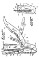
- Fig. 2 is an exploded perspective view of a fastener cartridge similar to that shown in Figs. 1A and B but possessing an improved body tissue cutting knife assembly in accordance with the present invention;
- Figs. 3A-C are perspective views of subassemblies (Figs. 3A and B) and the fully assembled (Fig. 3C) improved body tissue cutting knife assembly of Fig. 2;
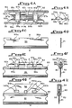
- Figs. 4A-H are enlarged views of the individual elements comprising the improved tissue cutting knife assembly of Figs. 3A-C with Figs. 4A and 4B illustrating, respectively, plan and cross-sectional views of the knife holder prior to being formed about the knife element, the latter being shown in side elevational and cross-sectional views, respectively, in Figs. 4C and 4D, and with Figs. 4E and 4F illustrating, respectively, side elevational and cross-sectional views of the knife holder and knife element sub-assembly, the full knife assembly being shown in side elevational and cross-sectional views, respectively, in Figs. 4G and 4H; and,
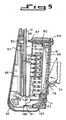
- Fig. 5 is an enlarged sectional view of a part of the fastener cartridge of Fig. 2 showing the operation of the device to cut and fasten body tissue.
- Figs. 1A and 1B are presented by way of illustrating a known type of fastener cartridge actuator apparatus, i.e., that described in U.S. Patent No. 4,665,916, which can be used in conjunction with the fastener cartridge of this invention featuring an improved surgical knife assembly. As shown in Figs. 1A and 1B, the known type of actuator device includes a
handle 20 adjacent the proximal end of the instrument, alongitudinal connecting structure 30 and an approximately U-shaped or V-shaped support structure 40 at the distal end of connectingstructure 30.Support structure 40 comprises aproximal leg 42, adistal leg 44, and abase 46 joining one end of each oflegs Support structure 40 lies in a plane substantially parallel to the longitudinal axis of connectingstructure 30. In use, the instrument is positioned relative totissue 12 to be fastened so that the tissue is generally betweenlegs support structure 40. -
Disposable fastener cartridge 50, shown in Fig. 1A about to be inserted withinleg 44 ofsupport structure 40 and in Fig. 1B, fully seated within said structure, includesfastener holder 52 andanvil support 54. Anvilsupport 54 is mounted intodistal leg 44 andfastener holder 52 is mounted intoproximal leg 42. The end ofcartridge 50 at whichpivotal axis 56 is located is inserted intobase 46.Pivotal axis 56 allows pivotal motion offastener holder 52 andanvil 54 relative to each other and, together withslots 105, also allows a limited amount of motion of the fastener holder perpendicular to anvilsurface 53. - Anvil
support 54 is designed to slide longitudinally into and out ofleg 44 ofsupport structure 40. The distal side ofanvil support 54 features aretaining structure 58 which fits betweenplates 44a and 44b ofdistal leg 44.Cartridge 50 is releasably retained withinleg 44 by a friction fit betweenretaining structure 58 andplates 44a and 44b, and is positioned accurately in the longitudinal direction ofleg 44 by the fit betweenprojections anvil support 54. Whencartridge 50 is positioned insupport structure 40 andprojections anvil support 54 will be located betweenplates 42a and 42b ofproximal leg 42. -
Disposable cartridge 50 of Figs. 1A and 1B, incorporating the improved body tissue cutting knife assembly of this invention, is shown in detail in the exploded perspective view of Fig. 2 and in the sectional view of Fig. 5. As shown in these drawings,fastener holder 52 accommodates a pair ofpusher holders fastener 120.Surface 53 of anvil support 54 directly opposite that of the fastener ejecting surfaces offastener storage elements apertures fastener retainer element 130 which is capable of locking with the prongs of anindividual fastener 120 upon actuation of the device. Behind eachfastener 120 is afastener pusher 62 slidably mounted inpusher holders cutting knife assembly 90 is driven in the distal direction along apassageway 61a located betweenpusher holders slot 61b (shown in Fig. 1A). As the knife assembly moves,shoulder 93 ofknife holder 92 contacts the proximal ends offastener pushers 62 thus causingpushers 62 to be moved in the distal direction alongguide slots 59 into whichprojections 67 of the pushers extend. Access toknife assembly 90 is through an elongated slot in the proximal side offastener holder 52 andelongated slot 88 inspring 81, to be discussed in more detail below.Fastener holder 52 normally is biased away fromanvil support 54 byleaf spring 51 andcoil spring 71. One end ofleaf spring 51 is retained withinslot 136 ofanvil support 54. The other end ofleaf spring 51 bears againstsurface 137 insidefastener holder 52.Spring 71 biasespivotal axis 56 to the distal end ofslots 105 and is kept in place byprojection 75 andcylindrical space 77. -
Fastener holder 52 also carriesalignment pin 80. In order to prevent the end ofalignment pin 80 from partly obstructing the open end ofcartridge 50 when the cartridge is open (which could present a possible hazard to the tissue being placed in, or removed from, the instrument), the pin is reciprocally mounted infastener holder 52 and provided with means for its automatic extension during the fastening operation and its automatic retraction whencartridge 50 is opened. The proximal end ofpin 80 is engaged by the slottedend 84 ofleaf spring 81 which extends along the proximal side offastener holder 52 and is anchored at the bottom offastener holder 52.Leaf spring 81 possesses anelongated slot 88 which is generally co-extensive with a slot formed infastener holder 52.Leaf spring 81 is so arranged that it will normally be inclined away from the proximal side offastener holder 52 in the direction towardpin 80. In this condition,spring 81 holdspin 80 in the retracted position so thatdistal end 86 ofpin 80 does not project fromfastener holder 52. As shown in Fig. 5,distal end 86 ofalignment pin 80 is advantageously provided with a point in order to enable the pin to easily piercetissue 12 as the pin is extended beyondfastener ejecting surface 55 during the fastening operation. - As shown in Figs. 1A and 5, when
tissue 12 is placed betweenfastener holder 52 andanvil support 54, pivotingclamp actuator 70 is pivoted clockwise about itspivotal axis 72 causingcamming surface 74 on the distal end ofactuator 70 to pivotfastener holder 52 counterclockwise about itspivotal axis 56 thereby gradually clampingtissue 12 betweenfastener holder 52 and opposinganvil surface 53. When actuator 70 has been fully pivoted clockwise so that it is substantially parallel to the longitudinal axis of connectingstructure 30 as shown in Fig. 1B,tissue 12 is then firmly clamped betweenanvil support surface 53 and opposingfastener ejecting surface 55. Asfastener holder 52 closes ontissue 12,alignment pin 80 pierces the tissue andspacer member 57 displaces thetissue surrounding pin 80 andcontacts anvil surface 53.Elongated apertures 105 allowpivotal axis 56 to translate linearly in the proximal direction through a relatively short distance thereby resulting infastener ejecting surface 55 and opposedanvil surface 53 being parallel to each other and ready for the firing offasteners 120 into the tissue clamped therebetween. - As
fastener holder 52 is pivoted counterclockwise byactuator 70, the tissue which would otherwise preventspacer member 57 from contactinganvil surface 53 is displaced by slopingsurfaces 57a and 57b of spacer member 57 (Fig. 1A). These surfaces slope towards each other to form a knife-like edge which displaces the tissue and permits the furthest-most projection, i.e.,surface 57c ofspacer member 57, to abut againstanvil surface 53. Proper alignment offastener holder 52 andanvil support 54 is aided byalignment pin 80 which extends through the side offastener holder 52 oppositepivotal axis 56 and into alignment pin aperture 82 (Fig. 5) inanvil support 54 asfastener holder surface 55 is pivoted parallel toanvil surface 53. Asfastener holder 52 is pivoted counterclockwise,alignment pin 80 extendspast spacer member 57 and makes contact with, and pushes through, the tissue located in front ofalignment pin aperture 82. Asfastener holder 52 continues to pivot counterclockwise,spacer member 57 reaches the tissue and begins to displace the tissue which is now surroundingalignment pin 80. Whenfastener holder 52 is fully pivoted,spacer member 57 has displaced the tissue so as to abut againstanvil surface 53 and ensure parallel alignment betweenfastener holder surface 55 andanvil surface 53. - As shown in Figs. 2, 3A-C and 4A-H, tissue cutting
knife assembly 90 is fabricated from aknife element 91 surmounted byknife holder 92 which in turn is enclosed byknife pusher 94. The knife holder is advantageously provided as a single piece of molded thermoplastic, e.g., a polycarbonate such as Makrolon (Bayer) or Lexan (General Electric), and possesses hinge elements 97a-e which are capable of at least one full flexure.Knife holder 92 is oriented with respect toknife element 91 in such a manner that upon folding of the knife holder about hinge elements 97a-e during the knife assembly manufacturing procedure, upwardly projectinglocking members 96a (shown by the dotted line in Fig. 3A) and 96b (shown in the partial cutaway view in Fig. 3A) engagekey elements knife element 91. Permanent joining ofopposed faces 92a and 92b ofknife holder 92 can be achieved in any convenient manner, e.g., employing a suitable adhesive, and as shown, is preferably accomplished by the known technique of ultrasonic welding, optionally supplemented by adhesive bonding. Joining offaces 92a and 92b results in mating engagement of ultrasonic welding bumps 98a and 98b defined on the interior wall of side 92b of the knife holder with corresponding ultrasonic welding pockets 98c and 98d, respectively, defined on the interior wall ofside 92a of the knife holder and locking engagement of lockingelements side 92a of the knife holder with correspondingkey elements knife element 91. Up-raisedlocking elements 99a-d provide sliding irreversible locking engagement with corresponding cut-outs 140a-d (cut-outs 100c and 100d are not shown) formed inknife pusher 94 and guideelements 141a and 141b lock with cut-outs 142a and 142b (cut-out 142b is not shown) so as to facilitate accurate positioning ofknife pusher 94 onknife holder 92 during assembly of these components. The space between the two opposed sides of the knife holder in effect constitutes a locking groove within whichknife 91 is permanently and irreversibly locked, a particularly advantageous construction since it eliminates any possibility that the knife element will accidentally disengage from the knife holder during actuation of the fastener cartridge cycle. In contrast to the highly secure locking groove feature of the improved knife holder herein, the known type of knife holder, e.g., that described in U.S. Patent No. 4,665,916, referred to supra, possesses a smooth continuous slot lacking lock-and-key or other functionally equivalent locking elements. - In the embodiment of the knife assembly shown in Figs. 3C and 4G-H,
knife pusher 94 is constructed of a stiff material, e.g., stainless steel, which is capable of withstanding the mechanical stress of the driving force directed against the knife assembly during actuation of the fastener applicator and encloses the upper section ofknife holder 92. Other configurations of the knife pusher can also be used; thus, e.g., this component can be provided as a strip of stress-resistant metal, e.g., stainless steel, covering only the top edge of the knife holder. - As shown in Figs. 1A, 1B and 4, when
actuator 70 is fully pivoted clockwise,driver 76, which is carried byactuator 70, also is substantially parallel to the longitudinal axis of connectingstructure 30. The distal end ofdriver 76 then extends into the proximal side offastener holder 52 and is adjacent the proximal surface of knife pusher member 94 (Fig. 2) in the fastener holder. Safety latch 100 (Fig. 1A), which normally keepsactuator lever 110 pivoted clockwise away fromhandle 20, is now released by pivoting it counterclockwise.Lever 110 can now be pivoted counterclockwise about pivotal axis 112 towardhandle 20, i.e., by squeezing it toward the handle with the fingers of the hand gripping the handle, to actuate the fastener driving mechanism. - When
lever 110 is pivoted counterclockwise as just described, the end oflever 110 inside the proximal end of connectingstructure 30 contacts theproximal end 78 ofdriver 76 and movesdriver 76 in the distal direction. The distal end ofdriver 76 contacts the proximal surface of knife-fastener pusher member 93 (Fig. 2), thereby drivingmember 93 in the distal direction and causing it to drivefasteners 120 out offastener holder 52 throughtissue 12 and intoretainers 130 held inanvil 54. Located slightly proximally of the distal end offasteners 120 isknife element 91 of knife assembly 90 (see Figs. 2, 3A-C and 4A-H). Afterfasteners 120 have begun to piercetissue 12,knife 91 begins to cut the tissue and to assure a complete cut, is caused to superficially penetrate a cutting block (not shown) associated withanvil 54. Aslever 110 is squeezed fully in the counterclockwise direction,fasteners 120 lock intoretainers 130 and knife surface 61 completely severstissue 12. - The joining of the tissue is now complete and all that remains to be done is to remove the fastened tissue from the instrument. This is accomplished by releasing
lever 110 which, because leaf springs 69 biases knife-fastener pusher member 93 in the proximal direction, causes knife-fastener pusher member 93 to retract intofastener holder 52.Actuator 70 is rotated in the counterclockwise direction andfastener holder 52 pivots clockwise away fromanvil 54 in response to the pressure ofleaf spring 51. In addition,spring 81biases alignment pin 80 away fromanvil 54 and thus retractspin 80 intofastener holder 52.Tissue 12 can now be readily withdrawn from the instrument.Cartridge 50 is now removed from the instrument by pullinganvil 54 out ofdistal leg 44. The expended cartridge can be discarded and another cartridge is loaded in the instrument if additional tissue fastening is required during the surgical procedure. When the surgical procedure is completed,instrument 10, if of the disposable type, is safely discarded or, if of the reusable type, is cleaned and sterilized to prepare it for use in another surgical procedure. - It will be understood that the embodiment shown and described herein is only illustrative of the principles of the invention, and that various modifications can be made by those skilled in the art without departing from the scope and spirit of the invention. In particular, the invention has been described in conjunction with a fastener cartridge featuring an improved tissue cutting knife assembly and a permanent, reusable actuator device. The invention could also have been described in conjunction with a fully disposable instrument. When the entire instrument is disposable, as much of the instrument as possible can be constructed from relatively inexpensive materials such as plastic, or the like and only those parts of the instrument which are subjected to relatively high mechanical stress need be made of metal.
Claims (10)
- In a surgical fastener cartridge which is adapted for use with an actuator apparatus having a rigid frame and a generally U-shaped portion for receiving the fastener cartridge, the actuator apparatus actuating the fastener cartridge to apply substantially parallel rows of fasteners to the tissue on both sides of a line of incision formed by a body tissue cutting knife assembly included within the fastener cartridge, said fastener cartridge possessing:a) a fastener holder containing a quantity of fasteners, the fasteners being driven, upon actuation of the fastener cartridge, through substantially parallel rows of apertures defined upon a fastener ejecting surface of the fastener holder;b) an anvil having a surface opposed to the fastener ejecting surface of the fastener holder and, upon actuation of the fastener cartridge, cooperating therewith to apply substantially parallel rows of fasteners to body tissue positioned between the fastener holder and anvil;c) means for driving the fasteners through the apertures upon actuation of the fastener cartridge;d) a tissue cutting knife assembly including (i) a knife element having an upper non-cutting edge and a lower cutting edge, (ii) a knife holder engaging the upper edge of the knife element and (iii) a knife pusher enclosing the knife holder, the cutting edge of the knife element being recessed within the fastener holder in the non-actuated condition of the fastener cartridge and, upon actuation of the fastener cartridge, extending beyond a slot formed between the rows of apertures; and,e) means for driving the cutting edge of the knife assembly through the slot upon actuation of the fastener cartridge,
the improvement which comprises a knife holder having two opposed sides defining at their lower sections a groove therebetween, the knife element being received into, and held in permanent and irreversible locking engagement with, the groove. - 2. The surgical fastener cartridge of Claim 1 wherein the groove of the knife holder possesses one or more locking elements which provide locking engagement with the upper edge of the knife element.
- 3. The surgical fastener cartridge of Claim 2 wherein the groove of the knife holder possess one or more locking elements which cooperate with corresponding key elements formed upon the upper edge of the knife element to provide permanent and irreversible locking engagement therewith.
- 4. The surgical fastener cartridge of Claim 1 wherein the knife holder is fabricated from a thermoplastic.
- 5. The surgical fastener cartridge of Claim 1 wherein the knife holder is fabricated from a single piece of thermoplastic having two opposed sides joined through one or more hinge elements capable of at least one full flexure.
- 6. The surgical fastener cartridge of Claim 5 wherein the thermoplastic is a polycarbonate.
- 7. The surgical fastener cartridge of Claim 2 wherein the knife holder is fabricated from a single piece of thermoplastic having two opposed sides joined through one or more hinge elements capable of at least one full flexure.
- 8. The surgical fastener cartridge of Claim 7 wherein the thermoplastic is a polycarbonate.
- 9. The surgical fastener cartridge of Claim 3 wherein the knife holder is fabricated from a single piece of thermoplastic having two opposed sides joined through one or more hinge elements capable of at least one full flexure.
- 10. The surgical fastener cartridge of Claim 9 wherein the thermoplastic is a polycarbonate.
Applications Claiming Priority (2)
| Application Number | Priority Date | Filing Date | Title |
|---|---|---|---|
| US07/281,552 US4881545A (en) | 1988-12-08 | 1988-12-08 | Surgical fastener cartridge with improved body tissue cutting knife assembly |
| US281552 | 1988-12-08 |
Publications (2)
| Publication Number | Publication Date |
|---|---|
| EP0373823A2 true EP0373823A2 (en) | 1990-06-20 |
| EP0373823A3 EP0373823A3 (en) | 1990-10-31 |
Family
ID=23077767
Family Applications (1)
| Application Number | Title | Priority Date | Filing Date |
|---|---|---|---|
| EP19890312707 Ceased EP0373823A3 (en) | 1988-12-08 | 1989-12-06 | Surgical fastener cartridge with improved body tissue cutting knife assembly |
Country Status (3)
| Country | Link |
|---|---|
| US (1) | US4881545A (en) |
| EP (1) | EP0373823A3 (en) |
| CA (1) | CA2004767C (en) |
Cited By (6)
| Publication number | Priority date | Publication date | Assignee | Title |
|---|---|---|---|---|
| US6805273B2 (en) | 2002-11-04 | 2004-10-19 | Federico Bilotti | Surgical stapling instrument |
| EP1550412A2 (en) * | 2003-12-30 | 2005-07-06 | Ethicon Endo-Surgery, Inc. | Knife retraction arm for a curved cutter stapler |
| EP1550409A1 (en) * | 2003-12-30 | 2005-07-06 | Ethicon Endo-Surgery, Inc. | Replaceable cartridge module for a surgical stapling and cutting instrument |
| EP1552791A1 (en) * | 2003-12-30 | 2005-07-13 | Ethicon Endo-Surgery, Inc. | Cartridge retainer for a curved cutter stapler |
| US6988650B2 (en) | 2003-12-30 | 2006-01-24 | Ethicon Endo-Surgery, Inc. | Retaining pin lever advancement mechanism for a curved cutter stapler |
| AU2011205154B2 (en) * | 2003-12-30 | 2012-05-31 | Ethicon Endo-Surgery, Inc. | Replaceable cartridge module for a surgical stapling and cutting instrument |
Families Citing this family (65)
| Publication number | Priority date | Publication date | Assignee | Title |
|---|---|---|---|---|
| US5100042A (en) * | 1990-03-05 | 1992-03-31 | United States Surgical Corporation | Surgical fastener apparatus |
| US5116349A (en) * | 1990-05-23 | 1992-05-26 | United States Surgical Corporation | Surgical fastener apparatus |
| US5470009A (en) * | 1990-12-06 | 1995-11-28 | United States Surgical Corporation | Surgical fastening apparatus with locking mechanism |
| CA2055943C (en) * | 1990-12-06 | 2003-09-23 | Daniel P. Rodak | Surgical fastening apparatus with locking mechanism |
| AU662719B2 (en) * | 1990-12-18 | 1995-09-14 | United States Surgical Corporation | Safety device for a surgical stapler cartridge |
| US5413267A (en) * | 1991-05-14 | 1995-05-09 | United States Surgical Corporation | Surgical stapler with spent cartridge sensing and lockout means |
| CA2078794C (en) * | 1991-10-18 | 1998-10-06 | Frank J. Viola | Locking device for an apparatus for applying surgical fasteners |
| US5395034A (en) * | 1991-11-07 | 1995-03-07 | American Cyanamid Co. | Linear surgical stapling instrument |
| US5368599A (en) * | 1992-10-08 | 1994-11-29 | United States Surgical Corporation | Surgical fastening apparatus with suture array |
| US5441193A (en) * | 1993-09-23 | 1995-08-15 | United States Surgical Corporation | Surgical fastener applying apparatus with resilient film |
| US5439155A (en) * | 1993-10-07 | 1995-08-08 | United States Surgical Corporation | Cartridge for surgical fastener applying apparatus |
| US5470008A (en) * | 1993-12-20 | 1995-11-28 | United States Surgical Corporation | Apparatus for applying surgical fasteners |
| US5465895A (en) * | 1994-02-03 | 1995-11-14 | Ethicon Endo-Surgery, Inc. | Surgical stapler instrument |
| US5636779A (en) * | 1994-12-13 | 1997-06-10 | United States Surgical Corporation | Apparatus for applying surgical fasteners |
| US5988479A (en) * | 1994-12-13 | 1999-11-23 | United States Surgical Corporation | Apparatus for applying surgical fasteners |
| US5706998A (en) * | 1995-07-17 | 1998-01-13 | United States Surgical Corporation | Surgical stapler with alignment pin locking mechanism |
| US5651491A (en) * | 1995-10-27 | 1997-07-29 | United States Surgical Corporation | Surgical stapler having interchangeable loading units |
| US5810240A (en) * | 1996-03-15 | 1998-09-22 | United States Surgical Corporation | Surgical fastener applying device |
| US6109500A (en) | 1996-10-04 | 2000-08-29 | United States Surgical Corporation | Lockout mechanism for a surgical stapler |
| DE10026683C2 (en) * | 2000-05-30 | 2003-07-10 | Ethicon Endo Surgery Europe | Surgical stapling device |
| US6817508B1 (en) | 2000-10-13 | 2004-11-16 | Tyco Healthcare Group, Lp | Surgical stapling device |
| US7407076B2 (en) | 2000-10-13 | 2008-08-05 | Tyco Healthcare Group Lp | Surgical stapling device |
| US20050143759A1 (en) * | 2003-12-30 | 2005-06-30 | Kelly William D. | Curved cutter stapler shaped for male pelvis |
| US20060219753A1 (en) * | 2005-04-01 | 2006-10-05 | Kwok-Wai Chiu | Circumcision apparatus and method using the same |
| US9636111B2 (en) | 2007-05-07 | 2017-05-02 | Covidien Lp | Method of stapling tissues with a staple assembly |
| US8348972B2 (en) | 2007-07-11 | 2013-01-08 | Covidien Lp | Surgical staple with augmented compression area |
| US8231040B2 (en) | 2008-04-14 | 2012-07-31 | Tyco Healthcare Group Lp | Variable compression surgical fastener cartridge |
| US8100310B2 (en) | 2008-04-14 | 2012-01-24 | Tyco Healthcare Group Lp | Variable compression surgical fastener apparatus |
| US7926691B2 (en) | 2008-04-14 | 2011-04-19 | Tyco Healthcare Group, L.P. | Variable compression surgical fastener cartridge |
| US8231041B2 (en) | 2008-04-14 | 2012-07-31 | Tyco Healthcare Group Lp | Variable compression surgical fastener cartridge |
| US7997468B2 (en) * | 2008-05-05 | 2011-08-16 | Tyco Healthcare Group Lp | Surgical instrument with clamp |
| CA2665017A1 (en) | 2008-05-05 | 2009-11-05 | Tyco Healthcare Group Lp | Surgical instrument with sequential clamping and cutting |
| US8186556B2 (en) | 2008-05-09 | 2012-05-29 | Tyco Healthcare Group Lp | Variable compression surgical fastener apparatus |
| US8967446B2 (en) | 2008-05-09 | 2015-03-03 | Covidien Lp | Variable compression surgical fastener cartridge |
| US9016541B2 (en) | 2008-05-09 | 2015-04-28 | Covidien Lp | Varying tissue compression with an anvil configuration |
| US8091756B2 (en) | 2008-05-09 | 2012-01-10 | Tyco Healthcare Group Lp | Varying tissue compression using take-up component |
| US8464922B2 (en) | 2008-05-09 | 2013-06-18 | Covidien Lp | Variable compression surgical fastener cartridge |
| US8016176B2 (en) * | 2008-06-04 | 2011-09-13 | Tyco Healthcare Group, Lp | Surgical stapling instrument with independent sequential firing |
| US8424738B2 (en) | 2008-06-04 | 2013-04-23 | Covidien Lp | Attachable clamp for surgical stapler |
| US20100023052A1 (en) * | 2008-07-23 | 2010-01-28 | Tyco Healthcare Group Lp | Staple for use in surgical procedures |
| US8070038B2 (en) | 2008-10-10 | 2011-12-06 | Tyco Healthcare Group, Lp | Surgical instrument with pivotable jaw member |
| US8393516B2 (en) * | 2009-02-26 | 2013-03-12 | Covidien Lp | Surgical stapling apparatus with curved cartridge and anvil assemblies |
| US8113409B2 (en) | 2009-03-31 | 2012-02-14 | Tyco Healthcare Group Lp | Surgical stapling apparatus with clamping assembly |
| US8328064B2 (en) | 2009-05-06 | 2012-12-11 | Covidien Lp | Pin locking mechanism for a surgical instrument |
| US8353436B2 (en) | 2009-05-06 | 2013-01-15 | Covidien Lp | Pin locking mechanism for a surgical instrument |
| US9023069B2 (en) | 2009-05-18 | 2015-05-05 | Covidien Lp | Attachable clamp for use with surgical instruments |
| US8827137B2 (en) | 2010-03-25 | 2014-09-09 | Covidien Lp | Pin alignment assembly for surgical stapler |
| US8940000B2 (en) | 2010-05-12 | 2015-01-27 | Covidien Lp | Surgical instruments with flexible member attachment structures |
| US8348124B2 (en) | 2011-02-08 | 2013-01-08 | Covidien Lp | Knife bar with geared overdrive |
| US20130140341A1 (en) * | 2011-12-02 | 2013-06-06 | Darin M. Minkin | Linear stapled hemorrhoidectomy systems and methods |
| US9168042B2 (en) * | 2012-01-12 | 2015-10-27 | Covidien Lp | Circular stapling instruments |
| CN102652683A (en) * | 2012-04-13 | 2012-09-05 | 北京中法派尔特医疗设备有限公司 | Cartridge assembly and bladed stitching instrument using cartridge assembly |
| US9707005B2 (en) | 2014-02-14 | 2017-07-18 | Ethicon Llc | Lockout mechanisms for surgical devices |
| JP6484341B2 (en) | 2014-12-25 | 2019-03-13 | コヴィディエン リミテッド パートナーシップ | Surgical stapling device |
| US9775611B2 (en) | 2015-01-06 | 2017-10-03 | Covidien Lp | Clam shell surgical stapling loading unit |
| US9855040B2 (en) | 2015-03-04 | 2018-01-02 | Covidien Lp | Surgical stapling loading unit having articulating jaws |
| USD814632S1 (en) | 2016-10-21 | 2018-04-03 | Covidien Lp | Staple cartridge |
| AU2017258826A1 (en) | 2016-12-02 | 2018-06-21 | Covidien Lp | Surgical stapling instrument with curved end effector |
| US10993714B2 (en) | 2017-11-28 | 2021-05-04 | Covidien Lp | Surgical stapling instrument and associated trigger mechanisms |
| US10945730B2 (en) | 2018-06-25 | 2021-03-16 | Covidien Lp | Stapling device with selectively advanceable alignment pin |
| CN114206227A (en) | 2019-08-02 | 2022-03-18 | 柯惠有限合伙公司 | Surgical stapling device with bending tool assembly |
| EP4051133A4 (en) | 2019-11-01 | 2023-06-28 | Covidien LP | Surgical stapling device with knife blade lock |
| JP2023513999A (en) | 2019-12-18 | 2023-04-05 | コヴィディエン リミテッド パートナーシップ | Surgical stapling device with shipping cap |
| EP4132373A4 (en) * | 2020-04-09 | 2024-01-03 | Covidien Lp | Anvil assembly with cutting plate |
| US11744584B2 (en) | 2020-06-09 | 2023-09-05 | Covidien Lp | Alignment pin assembly for surgical stapler |
Citations (2)
| Publication number | Priority date | Publication date | Assignee | Title |
|---|---|---|---|---|
| DE1774043U (en) * | 1958-03-20 | 1958-09-11 | Heinrich Dietrich | RAZOR. |
| US4665916A (en) * | 1985-08-09 | 1987-05-19 | United States Surgical Corporation | Surgical stapler apparatus |
Family Cites Families (4)
| Publication number | Priority date | Publication date | Assignee | Title |
|---|---|---|---|---|
| SU942719A1 (en) * | 1979-11-23 | 1982-07-15 | Всесоюзный научно-исследовательский и испытательный институт медицинской техники | Surgical suturing apparatus for application of linear sutures |
| SU1069794A1 (en) * | 1983-01-21 | 1984-01-30 | 1-Й Московский Ордена Ленина И Ордена Трудового Красного Знамени Медицинский Институт Им.И.М.Сеченова. | Surgical suture application for putting line stitch |
| US4676245A (en) * | 1983-02-09 | 1987-06-30 | Mamoru Fukuda | Interlocking surgical staple assembly |
| US4617928A (en) * | 1984-09-17 | 1986-10-21 | Alfranca Jose Maria P | Surgical instrument for practicing mechanical sutures and biopsies |
-
1988
- 1988-12-08 US US07/281,552 patent/US4881545A/en not_active Expired - Lifetime
-
1989
- 1989-12-06 CA CA002004767A patent/CA2004767C/en not_active Expired - Lifetime
- 1989-12-06 EP EP19890312707 patent/EP0373823A3/en not_active Ceased
Patent Citations (2)
| Publication number | Priority date | Publication date | Assignee | Title |
|---|---|---|---|---|
| DE1774043U (en) * | 1958-03-20 | 1958-09-11 | Heinrich Dietrich | RAZOR. |
| US4665916A (en) * | 1985-08-09 | 1987-05-19 | United States Surgical Corporation | Surgical stapler apparatus |
Cited By (18)
| Publication number | Priority date | Publication date | Assignee | Title |
|---|---|---|---|---|
| USRE40237E1 (en) * | 2000-05-30 | 2008-04-15 | Ethicon Endo-Surgery, Inc. | Surgical stapling instrument |
| US8646673B2 (en) | 2001-03-29 | 2014-02-11 | Ethicon Endo-Surgery, Inc. | Surgical stapling instrument |
| US6805273B2 (en) | 2002-11-04 | 2004-10-19 | Federico Bilotti | Surgical stapling instrument |
| US7147140B2 (en) | 2003-12-30 | 2006-12-12 | Ethicon Endo - Surgery, Inc. | Cartridge retainer for a curved cutter stapler |
| CN100450449C (en) * | 2003-12-30 | 2009-01-14 | 伊西康内外科公司 | Cartridge retainer for a curved cutter stapler |
| JP2005193033A (en) * | 2003-12-30 | 2005-07-21 | Ethicon Endo Surgery Inc | Surgical instrument adapted to apply a plurality of surgical fasteners to tissue of body |
| US6988650B2 (en) | 2003-12-30 | 2006-01-24 | Ethicon Endo-Surgery, Inc. | Retaining pin lever advancement mechanism for a curved cutter stapler |
| US7134587B2 (en) | 2003-12-30 | 2006-11-14 | Ethicon Endo-Surgery, Inc. | Knife retraction arm for a curved cutter stapler |
| EP1552791A1 (en) * | 2003-12-30 | 2005-07-13 | Ethicon Endo-Surgery, Inc. | Cartridge retainer for a curved cutter stapler |
| EP1550409A1 (en) * | 2003-12-30 | 2005-07-06 | Ethicon Endo-Surgery, Inc. | Replaceable cartridge module for a surgical stapling and cutting instrument |
| EP1550412A3 (en) * | 2003-12-30 | 2005-07-20 | Ethicon Endo-Surgery, Inc. | Knife retraction arm for a curved cutter stapler |
| CN100450450C (en) * | 2003-12-30 | 2009-01-14 | 伊西康内外科公司 | Knife retraction arm for a curved cutter stapler |
| AU2004242492B2 (en) * | 2003-12-30 | 2011-09-15 | Ethicon Endo-Surgery, Inc. | Knife retraction arm for a curved cutter stapler |
| AU2004242484B2 (en) * | 2003-12-30 | 2011-10-06 | Ethicon Endo-Surgery, Inc. | Cartridge retainer for a curved cutter stapler |
| CN102423267A (en) * | 2003-12-30 | 2012-04-25 | 伊西康内外科公司 | Replaceable cartridge module for a surgical stapling and cutting instrument |
| AU2011205154B2 (en) * | 2003-12-30 | 2012-05-31 | Ethicon Endo-Surgery, Inc. | Replaceable cartridge module for a surgical stapling and cutting instrument |
| EP1550412A2 (en) * | 2003-12-30 | 2005-07-06 | Ethicon Endo-Surgery, Inc. | Knife retraction arm for a curved cutter stapler |
| CN102423267B (en) * | 2003-12-30 | 2014-11-19 | 伊西康内外科公司 | Replaceable cartridge module for a surgical stapling and cutting instrument |
Also Published As
| Publication number | Publication date |
|---|---|
| CA2004767C (en) | 1999-07-27 |
| CA2004767A1 (en) | 1990-06-08 |
| EP0373823A3 (en) | 1990-10-31 |
| US4881545A (en) | 1989-11-21 |
Similar Documents
| Publication | Publication Date | Title |
|---|---|---|
| US4881545A (en) | Surgical fastener cartridge with improved body tissue cutting knife assembly | |
| US4819853A (en) | Surgical fastener cartridge | |
| US4665916A (en) | Surgical stapler apparatus | |
| US4591085A (en) | Surgical instrument for applying fasteners, said instrument having an improved trigger interlocking mechanism (Case VI) | |
| US4585153A (en) | Surgical instrument for applying two-piece fasteners comprising frictionally held U-shaped staples and receivers (Case III) | |
| US4605004A (en) | Surgical instrument for applying fasteners said instrument including force supporting means (case IV) | |
| EP0169044B1 (en) | "w" shaped staples and slotted receivers | |
| US4606345A (en) | Surgical instrument for applying two-piece fasteners comprising U-shaped staples and frictionally held receivers (Case II) | |
| US5456400A (en) | Apparatus and clip for fastening body tissue | |
| US4506671A (en) | Apparatus for applying two-part surgical fasteners | |
| EP0458568B1 (en) | Surgical fastener apparatus | |
| US6681978B2 (en) | Surgical stapler | |
| US4741336A (en) | Shaped staples and slotted receivers (case VII) | |
| US4863088A (en) | Surgical stapling instrument | |
| US4606344A (en) | Surgical instrument for applying fasteners having improved gap indicating means (Case V) | |
| US5551622A (en) | Surgical stapler | |
| US4881544A (en) | Surgical stapler apparatus with improved tissue shield | |
| US5443197A (en) | Locking mechanism for a skin stapler cartridge | |
| JPH07108295B2 (en) | Surgical stapler | |
| JPS6012047A (en) | Instrument for adapting clasp to tissue by using pair of hollow needles | |
| JP2004344660A (en) | Surgical stapler having lockout for used cartridge | |
| JPH06121798A (en) | Arched apparatus for attaching two part surgery pin | |
| JPH03155851A (en) | Device for mounting fastening for surgical application | |
| EP2762089B1 (en) | Delivering bioabsorbable fasteners |
Legal Events
| Date | Code | Title | Description |
|---|---|---|---|
| PUAI | Public reference made under article 153(3) epc to a published international application that has entered the european phase |
Free format text: ORIGINAL CODE: 0009012 |
|
| AK | Designated contracting states |
Kind code of ref document: A2 Designated state(s): DE FR GB |
|
| PUAL | Search report despatched |
Free format text: ORIGINAL CODE: 0009013 |
|
| AK | Designated contracting states |
Kind code of ref document: A3 Designated state(s): DE FR GB |
|
| 17P | Request for examination filed |
Effective date: 19901213 |
|
| 17Q | First examination report despatched |
Effective date: 19930421 |
|
| STAA | Information on the status of an ep patent application or granted ep patent |
Free format text: STATUS: THE APPLICATION HAS BEEN REFUSED |
|
| 18R | Application refused |
Effective date: 19940827 |