EP0375147A2 - Method of operating pulsed droplet deposition apparatus - Google Patents
Method of operating pulsed droplet deposition apparatus Download PDFInfo
- Publication number
- EP0375147A2 EP0375147A2 EP89311836A EP89311836A EP0375147A2 EP 0375147 A2 EP0375147 A2 EP 0375147A2 EP 89311836 A EP89311836 A EP 89311836A EP 89311836 A EP89311836 A EP 89311836A EP 0375147 A2 EP0375147 A2 EP 0375147A2
- Authority
- EP
- European Patent Office
- Prior art keywords
- droplet
- liquid
- pulse
- pulses
- expulsion
- Prior art date
- Legal status (The legal status is an assumption and is not a legal conclusion. Google has not performed a legal analysis and makes no representation as to the accuracy of the status listed.)
- Withdrawn
Links
Images


Classifications
-
- B—PERFORMING OPERATIONS; TRANSPORTING
- B41—PRINTING; LINING MACHINES; TYPEWRITERS; STAMPS
- B41J—TYPEWRITERS; SELECTIVE PRINTING MECHANISMS, i.e. MECHANISMS PRINTING OTHERWISE THAN FROM A FORME; CORRECTION OF TYPOGRAPHICAL ERRORS
- B41J2/00—Typewriters or selective printing mechanisms characterised by the printing or marking process for which they are designed
- B41J2/005—Typewriters or selective printing mechanisms characterised by the printing or marking process for which they are designed characterised by bringing liquid or particles selectively into contact with a printing material
- B41J2/01—Ink jet
- B41J2/015—Ink jet characterised by the jet generation process
- B41J2/04—Ink jet characterised by the jet generation process generating single droplets or particles on demand
- B41J2/045—Ink jet characterised by the jet generation process generating single droplets or particles on demand by pressure, e.g. electromechanical transducers
- B41J2/04501—Control methods or devices therefor, e.g. driver circuits, control circuits
- B41J2/04516—Control methods or devices therefor, e.g. driver circuits, control circuits preventing formation of satellite drops
-
- B—PERFORMING OPERATIONS; TRANSPORTING
- B41—PRINTING; LINING MACHINES; TYPEWRITERS; STAMPS
- B41J—TYPEWRITERS; SELECTIVE PRINTING MECHANISMS, i.e. MECHANISMS PRINTING OTHERWISE THAN FROM A FORME; CORRECTION OF TYPOGRAPHICAL ERRORS
- B41J2/00—Typewriters or selective printing mechanisms characterised by the printing or marking process for which they are designed
- B41J2/005—Typewriters or selective printing mechanisms characterised by the printing or marking process for which they are designed characterised by bringing liquid or particles selectively into contact with a printing material
- B41J2/01—Ink jet
- B41J2/015—Ink jet characterised by the jet generation process
- B41J2/04—Ink jet characterised by the jet generation process generating single droplets or particles on demand
- B41J2/045—Ink jet characterised by the jet generation process generating single droplets or particles on demand by pressure, e.g. electromechanical transducers
- B41J2/04501—Control methods or devices therefor, e.g. driver circuits, control circuits
- B41J2/0458—Control methods or devices therefor, e.g. driver circuits, control circuits controlling heads based on heating elements forming bubbles
-
- B—PERFORMING OPERATIONS; TRANSPORTING
- B41—PRINTING; LINING MACHINES; TYPEWRITERS; STAMPS
- B41J—TYPEWRITERS; SELECTIVE PRINTING MECHANISMS, i.e. MECHANISMS PRINTING OTHERWISE THAN FROM A FORME; CORRECTION OF TYPOGRAPHICAL ERRORS
- B41J2/00—Typewriters or selective printing mechanisms characterised by the printing or marking process for which they are designed
- B41J2/005—Typewriters or selective printing mechanisms characterised by the printing or marking process for which they are designed characterised by bringing liquid or particles selectively into contact with a printing material
- B41J2/01—Ink jet
- B41J2/015—Ink jet characterised by the jet generation process
- B41J2/04—Ink jet characterised by the jet generation process generating single droplets or particles on demand
- B41J2/045—Ink jet characterised by the jet generation process generating single droplets or particles on demand by pressure, e.g. electromechanical transducers
- B41J2/04501—Control methods or devices therefor, e.g. driver circuits, control circuits
- B41J2/04581—Control methods or devices therefor, e.g. driver circuits, control circuits controlling heads based on piezoelectric elements
-
- B—PERFORMING OPERATIONS; TRANSPORTING
- B41—PRINTING; LINING MACHINES; TYPEWRITERS; STAMPS
- B41J—TYPEWRITERS; SELECTIVE PRINTING MECHANISMS, i.e. MECHANISMS PRINTING OTHERWISE THAN FROM A FORME; CORRECTION OF TYPOGRAPHICAL ERRORS
- B41J2/00—Typewriters or selective printing mechanisms characterised by the printing or marking process for which they are designed
- B41J2/005—Typewriters or selective printing mechanisms characterised by the printing or marking process for which they are designed characterised by bringing liquid or particles selectively into contact with a printing material
- B41J2/01—Ink jet
- B41J2/015—Ink jet characterised by the jet generation process
- B41J2/04—Ink jet characterised by the jet generation process generating single droplets or particles on demand
- B41J2/045—Ink jet characterised by the jet generation process generating single droplets or particles on demand by pressure, e.g. electromechanical transducers
- B41J2/04501—Control methods or devices therefor, e.g. driver circuits, control circuits
- B41J2/04588—Control methods or devices therefor, e.g. driver circuits, control circuits using a specific waveform
Definitions
- This invention relates to methods of operating pulsed droplet deposition apparatus, such apparatus, more particularly, having a nozzle, a droplet liquid pressure chamber with which said nozzle communicates for the supply thereto of droplet liquid, droplet liquid replenishment means for replacing droplet liquid expelled from said chamber through said nozzle and electrically actuable means for imparting energy pulses to said droplet liquid to effect ejection of respective droplets from said nozzle.
- apparatus of the kind set forth.
- the droplet direction is influenced by the dynamics of its detachment.
- the end of the ligature remote from the ink droplet may randomly attach itself to the nozzle bore before finally becoming detached as the droplet draws the remote end of the ligature past the nozzle outlet orifice.
- the ligature at the instant of detachment is disposed at an inclination to the nozzle axis and thus results in the droplet direction being deflected from the nozzle axis, or if the ligature forms a satellite droplet, the latter moving in a different direction from that of the droplet.
- the present invention consists in the method of operating pulsed droplet deposition apparatus comprising a nozzle, a droplet liquid pressure chamber with which said nozzle communicates for the supply thereto of droplet liquid, droplet liquid replenishment means for replacing droplet liquid expelled from said chamber through said nozzle and electrically actuable means for imparting energy pulses to said droplet liquid to effect ejection of respective droplet sfrom said nozzle, said method comprising applying energy pulses to said droplets liquid in said chamber to effect expulsion of respective droplet from said nozzle, characterised by applying further energy pulses to said droplet liquid in said chamber respectively following the droplet expulsion pulses to effect droplet detachment from droplet liquid expelled from said chamber by way of said nozzle when the liquid has a meniscus which is convex in the sense of droplet motion said further energy pulses being of lower energy content than said droplet expulsion pulses and of insufficient energy content to effect droplet expulsion from said nozzle.
- the meniscus is thus in a positive, convex state at the instant of
- the method of operation is to apply each of said further energy pulses shortly prior to droplet detachment from droplet liquid in said nozzle.
- each of the further energy pulses is applied early in the process of droplet formation in liquid projected beyond the nozzle and prior to retraction of liquid back within the nozzle.
- the invention further consists in the method of operating droplet deposition apparatus comprising an array of parallel droplet liquid channels, nozzles respectively connected with said channels, droplet liquid supply means for replenishing droplet liquid expelled from said channels, successive of said channels being separated by channel dividing side walls formed with piezo-electric material poled in a direction normal to the array direction and to the longitudinal axes of said channels, electrodes on opposite channel facing surfaces of said side walls and electrically actuable means for applying voltage pulses to said electrodes of said channel side walls of channels selected for actuation to deflect said selected channel side walls in shear mode thereby to impart energy pulses to droplet liquid in said selected channels for droplet expulsion from the nozzles communicating with said selected channels, said method comprising operating said electrically actuable means to apply respective energy pulses to droplet liquid in selected channels of said array to effect expulsion of droplets from the nozzles communicating with said selected channels, characterised by operating said electrically actuable means to apply further energy pulses to droplet liquid in the selected channels respectively following the droplet expulsion
- said further energy pulses are applied each to all channels not selected for actuation.
- a nozzle 3 which communicates with a channel (not shown) of an array drop-on-demand ink jet printer, the channel having opposed side walls of piezo-electric material each provided on opposite sides thereof with respective electrodes to which a potential difference is applied in pulses to create a field normal to the sidewall, to the channel axis and to the direction of poling of the piezo-electric material of the sidewall.
- Such pulses effect deflection of the sidewalls of each of the channels in opposite senses in shear mode to cause an acoustic pressure wave to travel to and fro along the length of the channels which gives rise to droplet expulsion from the channels by way of the respective nozzles, such as nozzle 3, communicating therewith.
- the electrodes of the sidewalls of the channels of the array are connected to an LSI chip and the channels are arranged in two groups of alternate channels, the channels of each group being enabled to be fired to expel droplets by successive clock pulses applied to the LSI chip.
- the channels of each group which, when the channels of that group are enabled, are fired are determined by a multibit word supplied to the LSI chip.
- the channels may be arranged in more than two groups of interleaved channels, the groups of channels being successively enabled by successive clock pulses applied to the LSI chip so that selected channels of an enabled group can be simultaneously fired.
- the channels of the printhead each expel a plug of liquid from the associated nozzle which progressively forms a droplet 5 which on termination of the firing pulse, as the ink recedes into the nozzle forms a ligature 7 which connects the droplet with the body of ink in the nozzle.
- the receding ink in the nozzle bore has a meniscus 9 which is concave in the sense of droplet propulsion and as the ligature extends by reason of the movement in opposite senses of the meniscus and the droplet, the tail end 11 of the ligature is pulled towards the periphery of the meniscus.
- the ligature detaches from the meniscus or the nozzle side wall if it has been deflected so far and the tail end 11 at the instant of detachment is displaced from the nozzle axis. This induces an off axis velocity component at the tail end of the ligature which either disturbs the direction of travel of the droplet or generates a satellite droplet which goes off in a different direction from the droplet 5.
- Figure 2 illustrates a suitable voltage waveform 13 for operating the array printhead referred to and more fully described in co-pending European patent application 88300146.3, the waveform being supplied to electrodes on opposed walls of each of the channels which are to be activated and where a particular channel is to project droplets at maximum frequency, the waveform illustrated is, suitably, of frequency 1 to 5 KHz, the period of the waveform typically occupying 10-30 ⁇ secs.
- the waveform 13 comprises a ramp 15 during the fall of which from zero voltage, the opposed walls of the channel to which the waveform is applied relax outwards to enlarge the volume of the channel so that the channel takes in additional ink from the common ink supply to the channels of the array.
- the rate of fall of the ramp voltage is less than is required to expel a droplet from the immediately adjacent channels.
- the voltage remains constant over the remaining part 17 of the period of the waveform at the end of which the voltage level returns to zero.
- ink is taken in to the channel and when the voltage is returned to zero volts the channel walls move sharply towards one another to impart an energy pulse to the ink in the channel which effects droplet projection therefrom by causing an acoustic pressure wave to travel along the length of the channel.
- Figure 4 illustrates the development of a droplet expelled from a channel following firing of a channel by the waveform of Figure 2.
- ink has emerged from the outlet orifice of nozzle 3 and forms a meniscus 23 which is convex in the sense of motion of the ink.
- a cylindrical plug 25 of ink having the convex meniscus 23 at its forward end has formed.
- a neck 27 next begins to form at time C and by time D the neck has narrowed so defining droplet 29 from the forward part of the plug 25.
- the acoustic wave in the channel reverses so that by time E ligature 31 has formed and the body of ink to which the tail end 33 of the ligature is connected has drawn back into the nozzle and in so doing the meniscus 35 thereof has reversed to become concave in the direction of droplet motion.
- the tail end 33 of the meniscus has parted from the ink in the nozzle bore and prior to doing so has moved along the curve of the meniscus from the centre thereof.
- the ligature then either causes deflection of the droplet from its motion along the nozzle axis or breaks off from the droplet to form a satellite droplet which is smaller than the droplet 29.
- the voltage waveform 35 therein illustrated is employed in accordance with this invention to ensure that the droplet 29 or, if formed, a satellite thereof, are propelled along and not deflected from the nozzle bore axis.
- the waveform 35 has a first part or pulse 37 corresponding with the waveform 13 of Figure 2 and, following the first part, a second part or pulse 39 of the same general form as part 37 but of smaller amplitude than that of part 37 so that it gives rise to an energy pulse in the ink in the channel of energy content less than the value 21 (see Fig. 3) and which is of insufficient magnitude to cause droplet expulsion from the channel.
- the effect of this reversal of the meniscus is to cause the tail end 33 of the ligature 31 to be disposed at the centre of the meniscus 41 which lies on the nozzle axis at the time of detachment of the ligature from the body of ink in the nozzle.
- the development of an off axis velocity component at the tail end of the ligature is thus prevented and the droplet 29 and any satellite droplet thereof, if formed, are projected along the nozzle axis.
- the actual time of detachment is more a function of the nozzle and liquid parameters than characteristics of the actuator's acoustic length. Observations in the laboratory have shown the detachment time as being relatively independent of the driving wave form or its total energy. At low drive energies, the droplet velocity is lower and the ligature is shorter but the detachment occurs at the same time. Droplet detachment time is however affected by liquid viscosity so that if the apparatus were working in an environment where temperature changed substantially, it would be necessary to change the timing of the voltage waveform part 39 to control the droplet detachment in dependance upon viscosity variation.
- the waveform 45 of Figure 7 induces an early detachment of the droplet 29.
- Pulse or part 47 of the waveform corresponds with waveform part 39 of Figure 5 and gives rise to droplet formation conditions at times A to D as before.
- Pulse or part 49 of the waveform which imparts a further pulse of energy to the ink is initiated between times D and E by an instantaneous voltage rise 51 which rapidly reduces the ink pressure in the channel and causes the liquid meniscus to be forcibly driven from the convex configuration at time D to the concave configuration at time E so that the ligature 31 is broken before the tail end 33 thereof has moved along the meniscus towards the nozzle sidewall. Since the ligature 31 has very small volume there is no significant loss of droplet volume.
- the pressure in the channel is held reduced by keeping the voltage constant for an interval of time 53 and then restored gradually over a time interval when voltage 55 rises to zero.
- the waveforms described have an "arm and fire" part for, as the case may be, droplet expulsion or meniscus reversal
- these waveforms could alternatively be of the "fire and "arm” form described as the alternative form usable in the embodiment of Figures 5 and 6.
- the supplementary, meniscus reversing pulse necessarily must be of the kind where the leading edge thereof effects rapid lowering of the ink pressure in the channel so that rapid severance of the droplet ligature from the body of ink in the nozzle is effected.
- This method of forcing early droplet severance has the advantage of completing the droplet formation time sooner than is the case with waveform 35 thus allowing higher speed operation and more time for further correction of the resonant waves travelling in the adjacent channels.
- Another advantage is that if the ligature is short, then the likelihood of satellite generation is lowered and a higher droplet velocity can be employed.
- the secondary pulse 39 imparts further energy to the liquid in the actuated channel to ensure that the meniscus of the body of liquid to which the droplet attached is convex in the direction of droplet propulsion and, suitably, forward of the nozzle at the instant of droplet detachment which occurs after a constant interval following the termination of pulse 37.
- the secondary pulse 49 is applied at a time when the body of liquid to which the forming droplet is attached is outside the nozzle so that the meniscus formed on that body of liquid is convex and the effect of the pulse 49 is to cause droplet separation in a time earlier than would be the case were the waveform of Figure 5 employed.
- the waveforms of the secondary pulses 39 and 49 serve different purposes, pulse 39 ensuring that the meniscus of the body of liquid to which the droplet is attached is convex in the direction of droplet propulsion and the pulse 49 effecting, at a time when the meniscus is convex, earlier droplet separation at a time before the body of liquid has been drawn back into the nozzle.
- two further pulses following pulse 37 or 47 instead of a single pulse can be employed a first of which is applied, when the body of liquid to which the droplet is attached has been drawn back into the nozzle, to reverse the meniscus, which is then concave in the direction of droplet propulsion, to convex form, and, the second of which reverses the motion of the body of liquid projecting from the nozzle relatively to that of the droplet being formed to effect early separation of the droplet.
- FIG. 9 and 10 like parts are identified by the same reference numerals.
- the array printhead concerned is that described with reference to Figures 2(a) - (d) of co-pending European patent application No. 88300146.3.
- the electrode linings of the ink channels of the array are represented by electrodes 60 formed on facing surfaces of the channel dividing side walls and further electrodes 62 formed in one with the electrodes 60 and disposed on the facing surfaces of the top and bottom walls of the channels.
- the electrode lining of each channel has attached thereto an electrical connection 64 which connects with the LSI driver chip.
- the side walls of the channels which extend normal to plane containing the channel axes and to the array direction are of piezo-electric material poled in a direction normal to the plane containing the longitudinal axes of the channels and the sidewalls each deflect in shear mode when the electrodes on opposite sides thereof are subjected to a potential difference.
- Such potential difference is applied in opposite senses to the side walls of an actuated channel by holding the potential of the electrode linings of the channels on opposite sides of the actuated channel at ground potential whilst a positive or negative potential is applied to the electrode lining of the actuated channel. In this way the facing side walls of an actuated channel are deflected in shear mode in opposite senses.
- the channels are divided into two groups respectively of odd and even numbered channels, the channels of the groups being enabled by successive clock pulses applied to the LSI chip to which the connections 64 are attached.
- the channels of the groups being enabled by successive clock pulses applied to the LSI chip to which the connections 64 are attached.
- As each group of channels is enabled channels of the enabled group are selected for actuation by a multi-bit word applied by way of the LSI chip to each of the selected channels.
- the waveform 35 applied to a selected odd-numbered channel 67 is shown and is of the same form as illustrated in Figure 5.
- the even numbered channels on respective opposite sides of the selected odd numbered channels 69 are not actuated since that is the condition at the time of all the even numbered channels and, for the purpose of this description, it is assumed that the odd numbered channels 71 on the side of the illustrated even numbered channels 69 remote from channel 67 are also not selected for actuation. Accordingly, the line voltage 73 applied to the connections 64 of the illustrated unselected even and odd numbered channels is held to ground during the application to the selected odd numbered channel 67 of the voltage waveform 35.
- the condition of the field applied to the channel side walls which is followed by the deflection of those walls is shown as the waveform 35 is applied.
- the facing side walls of the selected channel 67 are seen for both the droplet ejection pulse 37 and the secondary pulse 39, first to deflect outwards then to dwell in the outwardly deflected position and thereafter to be brought instantaneously back to the initial position thereof.
- Droplet formation is initiated by termination of pulse 37 and droplet detachment occurs after time 75 i.e. shortly following termination of pulse 39 when the body of liquid projects from the channel nozzle and thus has a meniscus which is convex in the direction of droplet propulsion.
- the time 75 taken for droplet detachment is substantially constant and the secondary pulse is applied prior to droplet detachment.
- the secondary pulse of energy 77 imparted to the liquid in the selected channel 67 is achieved, not as in the case of the embodiment of Figure 9 by deflecting the channel side walls in the same sense as they are deflected by the pulse 37, but by deflecting them in the opposite sense.
- a unipolar LSI chip in the channel drive circuits and with such a chip it is not possible to apply to the selected channel side walls after the droplet forming and propulsion pulse, in this case referenced 76, a pulse of opposite polarity and lower amplitude.
- the desired effect of imparting energy to the liquid in the actuated channel by moving the side walls initially inwardly rather than outwardly can, it has been found, be achieved by applying, following the completion of pulse 76, secondary pulse 77 of the same polarity as pulse 76 to each wall of the non-selected odd numbered channels, such as channels 71, and all the even numbered channels, such as channel 69.
- the electrode of selected channel 67 is at ground potential whilst the electrodes of the adjacent even numbered channels are subject to the pulse 77.
- the side walls of the selected channel are therefore deflected in shear mode inwardly, as indicated on the righthand side of the drawing, applying a secondary energy pulse to the liquid in the channel.
- the behaviour is therefore as if there were a secondary voltage pulse on the selected odd numbered line 67 of opposite polarity to the first voltage pulse 76 thereon (though this is not possible since the LSI chip employed is unipolar).
- the secondary correction pulse causes an immediate increase in pressure and the same instant meniscus movement occurs on every actuated channel which results in improved print quality.
- the secondary, correction pulse 77 applied to all the non-actuated channels is of different form from pulse 39, having symmetrical leading and trailing ramps 81, 83 which results in a rounder meniscus profile.
- the correction pulse further is applied to both sides of the opposite side walls of all of the unactuated channels so that no field is applied to those side walls and no deflection thereof occurs and no meniscus motion is therefore generated in those channels.
- the channels of the array printhead being arranged in two groups respectively of odd and even numbered channels
- the invention is generally applicable to droplet deposition apparatus of the kind set forth.
- the invention can also be applied to such apparatus, as disclosed for example in United States patent 4,296,621 in which droplet projection is effected by a heating pulse applied to the ink channel, suitably, near the nozzle end thereof.
- the heating, droplet propulsion pulse is desirably of rectangular form.
- the supplementary pulse for effecting meniscus disposition in convex form in the sense of liquid motion, whether effected early or late in the process of droplet formation should also be of rectangular form and, of course, of energy content below the threshold at which droplet propulsion occurs.
Abstract

Description
- This invention relates to methods of operating pulsed droplet deposition apparatus, such apparatus, more particularly, having a nozzle, a droplet liquid pressure chamber with which said nozzle communicates for the supply thereto of droplet liquid, droplet liquid replenishment means for replacing droplet liquid expelled from said chamber through said nozzle and electrically actuable means for imparting energy pulses to said droplet liquid to effect ejection of respective droplets from said nozzle. Hereinafter, such apparatus is referred to as apparatus "of the kind set forth".
- Examples of such apparatus are droplet-on-demand ink jet printers as described, for example, in co-pending European patent applications Nos. 88300144.8 and 88300146.3, the contents of which are incorporated herein by reference.
- In a droplet-on-demand ink jet printer of the kind set forth, the droplet direction is influenced by the dynamics of its detachment. In particular if the severance of the ligature, formed prior to droplet detachment, connecting the droplet to the body of ink in the nozzle bore, takes place inside the nozzle bore, the end of the ligature remote from the ink droplet may randomly attach itself to the nozzle bore before finally becoming detached as the droplet draws the remote end of the ligature past the nozzle outlet orifice. Since the detachment now occurs at the edge of the nozzle outlet orifice, the ligature at the instant of detachment is disposed at an inclination to the nozzle axis and thus results in the droplet direction being deflected from the nozzle axis, or if the ligature forms a satellite droplet, the latter moving in a different direction from that of the droplet.
- It is an object of the present invention to provide an improved method of operating pulsed droplet deposition apparaus.
- It is a further object of the invention to afford a method of operating pulsed droplet deposition apparatus generally and droplet-on-demand ink jet printers in particular, so that the droplet detachment is so stabilised as to ensure that the droplet direction and, if formed, the satellite droplet direction is along the nozzle axis.
- The present invention consists in the method of operating pulsed droplet deposition apparatus comprising a nozzle, a droplet liquid pressure chamber with which said nozzle communicates for the supply thereto of droplet liquid, droplet liquid replenishment means for replacing droplet liquid expelled from said chamber through said nozzle and electrically actuable means for imparting energy pulses to said droplet liquid to effect ejection of respective droplet sfrom said nozzle, said method comprising applying energy pulses to said droplets liquid in said chamber to effect expulsion of respective droplet from said nozzle, characterised by applying further energy pulses to said droplet liquid in said chamber respectively following the droplet expulsion pulses to effect droplet detachment from droplet liquid expelled from said chamber by way of said nozzle when the liquid has a meniscus which is convex in the sense of droplet motion said further energy pulses being of lower energy content than said droplet expulsion pulses and of insufficient energy content to effect droplet expulsion from said nozzle. The meniscus is thus in a positive, convex state at the instant of ligature detachment which ensures that at that instant the ligature is disposed coaxially with respect to the nozzle.
- In one form of the invention, the method of operation is to apply each of said further energy pulses shortly prior to droplet detachment from droplet liquid in said nozzle. In an alternative method of operation each of the further energy pulses is applied early in the process of droplet formation in liquid projected beyond the nozzle and prior to retraction of liquid back within the nozzle.
- The invention further consists in the method of operating droplet deposition apparatus comprising an array of parallel droplet liquid channels, nozzles respectively connected with said channels, droplet liquid supply means for replenishing droplet liquid expelled from said channels, successive of said channels being separated by channel dividing side walls formed with piezo-electric material poled in a direction normal to the array direction and to the longitudinal axes of said channels, electrodes on opposite channel facing surfaces of said side walls and electrically actuable means for applying voltage pulses to said electrodes of said channel side walls of channels selected for actuation to deflect said selected channel side walls in shear mode thereby to impart energy pulses to droplet liquid in said selected channels for droplet expulsion from the nozzles communicating with said selected channels, said method comprising operating said electrically actuable means to apply respective energy pulses to droplet liquid in selected channels of said array to effect expulsion of droplets from the nozzles communicating with said selected channels, characterised by operating said electrically actuable means to apply further energy pulses to droplet liquid in the selected channels respectively following the droplet expulsion pulses to effect droplet detachment from droplet liquid expelled from the nozzles of said selected channels when at each of the nozzles of said selected channels the liquid to which the droplet is attached has a meniscus which is convex in the sense of droplet motion, said further energy pulses being each of lower energy content than said droplet expulsion pulses and of insufficient energy content itself to effect droplet expulsion from the corresponding nozzle.
- Suitably, said further energy pulses are applied each to all channels not selected for actuation.
- The invention will now be described, by way of example, with reference to the accompanying drawings, in which:-
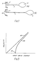
- FIGURES 1(a) and (b) illustrate the final part of the droplet formation and detachment process in a pulsed droplet deposition apparatus, e.g. a drop-on-demand ink jet printer of the kind described in the above-mentioned European patent applications;
- FIGURE 2 shows a voltage waveform employed for firing a droplet in a drop-on-demand ink jet printer as described in European patent application 88300146.3;
- FIGURE 3 illustrates the relationship between nozzle and droplet velocities and input pulse energy;
- FIGURE 4 shows a typical droplet evolution generated by the waveform of Figure 2;
- FIGURE 5 shows a voltage waveform employed in the method of operating pulsed droplet deposition apparatus according to this invention;
- FIGURE 6 shows a typical droplet evolution generated by the waveform of Figure 5;
- FIGURE 7 shows an alternative voltage waveform to that of Figure 5 which may be used to perform the method of the invention,
- FIGURE 8 shows a typical droplet evolution generated by the waveform of Figure 7,
- FIGURE 9 is a diagram illustrating the operation of an array type drop-on-demand printer employing the voltage waveform of Figure 5; and
- FIGURE 10 is a diagram similar to that of Figure 9 which illustrates a further embodiment of the invention.
- The process of droplet formation in a droplet deposition apparatus of the kind set forth is hereinafter described for convenience with reference to the drop-on-demand array printheads described with respect to Figures 1(a) to (c) and 2(a) to (d) of European patent application 88300146.3 although the phenomena of droplet separation as described in relation thereto arise in connection with other forms of array printhead as described in the said European patent application and indeed generally in relation to other forms of pulsed droplet deposition apparatus e.g. where droplet expulsion is effected by applying heat impulses to the droplet liquid.
- In Figure 1 there is illustrated a nozzle 3 which communicates with a channel (not shown) of an array drop-on-demand ink jet printer, the channel having opposed side walls of piezo-electric material each provided on opposite sides thereof with respective electrodes to which a potential difference is applied in pulses to create a field normal to the sidewall, to the channel axis and to the direction of poling of the piezo-electric material of the sidewall. Such pulses effect deflection of the sidewalls of each of the channels in opposite senses in shear mode to cause an acoustic pressure wave to travel to and fro along the length of the channels which gives rise to droplet expulsion from the channels by way of the respective nozzles, such as nozzle 3, communicating therewith. As described in the co-pending patent application referred to, the electrodes of the sidewalls of the channels of the array are connected to an LSI chip and the channels are arranged in two groups of alternate channels, the channels of each group being enabled to be fired to expel droplets by successive clock pulses applied to the LSI chip. The channels of each group which, when the channels of that group are enabled, are fired are determined by a multibit word supplied to the LSI chip. The channels may be arranged in more than two groups of interleaved channels, the groups of channels being successively enabled by successive clock pulses applied to the LSI chip so that selected channels of an enabled group can be simultaneously fired.
- When fired, the channels of the printhead each expel a plug of liquid from the associated nozzle which progressively forms a droplet 5 which on termination of the firing pulse, as the ink recedes into the nozzle forms a ligature 7 which connects the droplet with the body of ink in the nozzle. The receding ink in the nozzle bore has a
meniscus 9 which is concave in the sense of droplet propulsion and as the ligature extends by reason of the movement in opposite senses of the meniscus and the droplet, thetail end 11 of the ligature is pulled towards the periphery of the meniscus. In this movement the ligature detaches from the meniscus or the nozzle side wall if it has been deflected so far and thetail end 11 at the instant of detachment is displaced from the nozzle axis. This induces an off axis velocity component at the tail end of the ligature which either disturbs the direction of travel of the droplet or generates a satellite droplet which goes off in a different direction from the droplet 5. - Figure 2 illustrates a
suitable voltage waveform 13 for operating the array printhead referred to and more fully described in co-pending European patent application 88300146.3, the waveform being supplied to electrodes on opposed walls of each of the channels which are to be activated and where a particular channel is to project droplets at maximum frequency, the waveform illustrated is, suitably, of frequency 1 to 5 KHz, the period of the waveform typically occupying 10-30 µsecs. Thewaveform 13 comprises aramp 15 during the fall of which from zero voltage, the opposed walls of the channel to which the waveform is applied relax outwards to enlarge the volume of the channel so that the channel takes in additional ink from the common ink supply to the channels of the array. The rate of fall of the ramp voltage is less than is required to expel a droplet from the immediately adjacent channels. After the maximum negative voltage of theramp 15 is reached the voltage remains constant over theremaining part 17 of the period of the waveform at the end of which the voltage level returns to zero. During theconstant voltage part 17 of the waveform ink is taken in to the channel and when the voltage is returned to zero volts the channel walls move sharply towards one another to impart an energy pulse to the ink in the channel which effects droplet projection therefrom by causing an acoustic pressure wave to travel along the length of the channel. The acoustic wave continues, until damped out, to travel up and down the channel after droplet expulsion therefrom and during ink replenishment therein and causes oscillation of the meniscus in the nozzle bore. It will be apparent that during fall of the waveform voltage alongramp 15 the channel is being "armed" for droplet expulsion which occurs when the channel is "fired" by return to zero volts of the waveform voltage at the end of the period of the waveform. Thebroken line 19 in Figure 2 shows the threshold below which the waveform ramp voltage attained is insufficient to cause droplet expulsion from the channel. Figure 3 similarly shows graphically that for input energy pulses of value less than indicated bypoint 21, no droplet is emitted, the droplet and nozzle liquid velocities being shown by thecharacteristics - Figure 4 illustrates the development of a droplet expelled from a channel following firing of a channel by the waveform of Figure 2. As indicated, at time A after firing, ink has emerged from the outlet orifice of nozzle 3 and forms a
meniscus 23 which is convex in the sense of motion of the ink. Later at time B acylindrical plug 25 of ink having theconvex meniscus 23 at its forward end has formed. Aneck 27 next begins to form at time C and by time D the neck has narrowed so definingdroplet 29 from the forward part of theplug 25. Between times D and E the acoustic wave in the channel reverses so that bytime E ligature 31 has formed and the body of ink to which thetail end 33 of the ligature is connected has drawn back into the nozzle and in so doing themeniscus 35 thereof has reversed to become concave in the direction of droplet motion. At the later time F thetail end 33 of the meniscus has parted from the ink in the nozzle bore and prior to doing so has moved along the curve of the meniscus from the centre thereof. As previously intimated the ligature then either causes deflection of the droplet from its motion along the nozzle axis or breaks off from the droplet to form a satellite droplet which is smaller than thedroplet 29. - Turning to figure 5, the
voltage waveform 35 therein illustrated is employed in accordance with this invention to ensure that thedroplet 29 or, if formed, a satellite thereof, are propelled along and not deflected from the nozzle bore axis. Thewaveform 35 has a first part orpulse 37 corresponding with thewaveform 13 of Figure 2 and, following the first part, a second part orpulse 39 of the same general form aspart 37 but of smaller amplitude than that ofpart 37 so that it gives rise to an energy pulse in the ink in the channel of energy content less than the value 21 (see Fig. 3) and which is of insufficient magnitude to cause droplet expulsion from the channel. - As will be seen in Figure 6, following the application of
part 37 of the waveform to the channel side walls the ink droplet formation follows stages A to E as described for the waveform of Figure 2. It will be observed however that the channel is being re-armed by thepart 39 from time C through to a time E after which the re-arming voltage is held constant until a time slightly prior to time F, at which the channel is again fired so that at time F theconcave meniscus 35 present at time E has reversed to convexmeniscus 41 as the energy pulse attributable to waveformpart 39 reverses the flow of ink in the nozzle 3. The effect of this reversal of the meniscus is to cause thetail end 33 of theligature 31 to be disposed at the centre of themeniscus 41 which lies on the nozzle axis at the time of detachment of the ligature from the body of ink in the nozzle. The development of an off axis velocity component at the tail end of the ligature is thus prevented and thedroplet 29 and any satellite droplet thereof, if formed, are projected along the nozzle axis. - It has been found that at drives below the droplet emission threshold quite substantial ink plugs, such as
plug 25 in Figures 4 and 6 are generated. At the droplet emission threshold, the droplet size was measured as 70% to 80% of the volume of a three metre per second ejected droplet required for printing. If the drive pulse energy is lowered further, it is found that only a very small energy pulse is needed to effect the desired reversal of the meniscus. - The actual time of detachment is more a function of the nozzle and liquid parameters than characteristics of the actuator's acoustic length. Observations in the laboratory have shown the detachment time as being relatively independent of the driving wave form or its total energy. At low drive energies, the droplet velocity is lower and the ligature is shorter but the detachment occurs at the same time. Droplet detachment time is however affected by liquid viscosity so that if the apparatus were working in an environment where temperature changed substantially, it would be necessary to change the timing of the
voltage waveform part 39 to control the droplet detachment in dependance upon viscosity variation. - Although the embodiment of the invention described with reference to Figures 5 and 6 employs a voltage waveform of the "arm and fire" form, it is also possible to use a "fire and arm" type of waveform, that is to say one in which both the main or droplet projecting pulse and the supplementary or meniscus reversing pulse commence with an instantaneous fall of voltage which is followed by a constant voltage period and a slow rise of voltage thus effecting rapid movement of the channel walls to impart energy to the ink followed by holding the walls at their inward deflected position and then effecting slow restoration of the walls to their starting position.
- Referring now to Figures 7 and 8, the
waveform 45 of Figure 7 induces an early detachment of thedroplet 29. Pulse orpart 47 of the waveform corresponds withwaveform part 39 of Figure 5 and gives rise to droplet formation conditions at times A to D as before. Pulse orpart 49 of the waveform which imparts a further pulse of energy to the ink is initiated between times D and E by an instantaneous voltage rise 51 which rapidly reduces the ink pressure in the channel and causes the liquid meniscus to be forcibly driven from the convex configuration at time D to the concave configuration at time E so that theligature 31 is broken before thetail end 33 thereof has moved along the meniscus towards the nozzle sidewall. Since theligature 31 has very small volume there is no significant loss of droplet volume. The pressure in the channel is held reduced by keeping the voltage constant for an interval of time 53 and then restored gradually over a time interval when voltage 55 rises to zero. - In the embodiment of the invention described with reference to Figures 7 and 8 although the waveforms described have an "arm and fire" part for, as the case may be, droplet expulsion or meniscus reversal, these waveforms could alternatively be of the "fire and "arm" form described as the alternative form usable in the embodiment of Figures 5 and 6. However, the supplementary, meniscus reversing pulse necessarily must be of the kind where the leading edge thereof effects rapid lowering of the ink pressure in the channel so that rapid severance of the droplet ligature from the body of ink in the nozzle is effected.
- This method of forcing early droplet severance has the advantage of completing the droplet formation time sooner than is the case with
waveform 35 thus allowing higher speed operation and more time for further correction of the resonant waves travelling in the adjacent channels. Another advantage is that if the ligature is short, then the likelihood of satellite generation is lowered and a higher droplet velocity can be employed. - As will now be apparent, the waveform employed in the embodiment of the invention described with reference to Figures 5 and 6, the
secondary pulse 39 imparts further energy to the liquid in the actuated channel to ensure that the meniscus of the body of liquid to which the droplet attached is convex in the direction of droplet propulsion and, suitably, forward of the nozzle at the instant of droplet detachment which occurs after a constant interval following the termination ofpulse 37. However, in the embodiment of the invention described with reference to Figures 7 and 8, thesecondary pulse 49 is applied at a time when the body of liquid to which the forming droplet is attached is outside the nozzle so that the meniscus formed on that body of liquid is convex and the effect of thepulse 49 is to cause droplet separation in a time earlier than would be the case were the waveform of Figure 5 employed. Thus the waveforms of thesecondary pulses pulse 39 ensuring that the meniscus of the body of liquid to which the droplet is attached is convex in the direction of droplet propulsion and thepulse 49 effecting, at a time when the meniscus is convex, earlier droplet separation at a time before the body of liquid has been drawn back into the nozzle. - It follows, accordingly, that two further
pulses following pulse - In Figures 9 and 10 like parts are identified by the same reference numerals. In these Figures the array printhead concerned is that described with reference to Figures 2(a) - (d) of co-pending European patent application No. 88300146.3. The electrode linings of the ink channels of the array are represented by
electrodes 60 formed on facing surfaces of the channel dividing side walls and further electrodes 62 formed in one with theelectrodes 60 and disposed on the facing surfaces of the top and bottom walls of the channels. The electrode lining of each channel has attached thereto anelectrical connection 64 which connects with the LSI driver chip. The side walls of the channels which extend normal to plane containing the channel axes and to the array direction are of piezo-electric material poled in a direction normal to the plane containing the longitudinal axes of the channels and the sidewalls each deflect in shear mode when the electrodes on opposite sides thereof are subjected to a potential difference. Such potential difference is applied in opposite senses to the side walls of an actuated channel by holding the potential of the electrode linings of the channels on opposite sides of the actuated channel at ground potential whilst a positive or negative potential is applied to the electrode lining of the actuated channel. In this way the facing side walls of an actuated channel are deflected in shear mode in opposite senses. - In the printhead of Figures 9 and 10 the channels are divided into two groups respectively of odd and even numbered channels, the channels of the groups being enabled by successive clock pulses applied to the LSI chip to which the
connections 64 are attached. As each group of channels is enabled channels of the enabled group are selected for actuation by a multi-bit word applied by way of the LSI chip to each of the selected channels. - In Figure 9 the
waveform 35 applied to a selected odd-numberedchannel 67 is shown and is of the same form as illustrated in Figure 5. The even numbered channels on respective opposite sides of the selected odd numberedchannels 69 are not actuated since that is the condition at the time of all the even numbered channels and, for the purpose of this description, it is assumed that the odd numberedchannels 71 on the side of the illustrated even numberedchannels 69 remote fromchannel 67 are also not selected for actuation. Accordingly, theline voltage 73 applied to theconnections 64 of the illustrated unselected even and odd numbered channels is held to ground during the application to the selected odd numberedchannel 67 of thevoltage waveform 35. At the righthand side of the drawing, the condition of the field applied to the channel side walls which is followed by the deflection of those walls is shown as thewaveform 35 is applied. Thus, the facing side walls of the selectedchannel 67 are seen for both thedroplet ejection pulse 37 and thesecondary pulse 39, first to deflect outwards then to dwell in the outwardly deflected position and thereafter to be brought instantaneously back to the initial position thereof. Droplet formation is initiated by termination ofpulse 37 and droplet detachment occurs aftertime 75 i.e. shortly following termination ofpulse 39 when the body of liquid projects from the channel nozzle and thus has a meniscus which is convex in the direction of droplet propulsion. Thetime 75 taken for droplet detachment is substantially constant and the secondary pulse is applied prior to droplet detachment. - In the arrangement of Figure 10, the secondary pulse of
energy 77 imparted to the liquid in the selectedchannel 67 is achieved, not as in the case of the embodiment of Figure 9 by deflecting the channel side walls in the same sense as they are deflected by thepulse 37, but by deflecting them in the opposite sense. For reasons of economy it is desirable to employ a unipolar LSI chip in the channel drive circuits and with such a chip it is not possible to apply to the selected channel side walls after the droplet forming and propulsion pulse, in this case referenced 76, a pulse of opposite polarity and lower amplitude. However, the desired effect of imparting energy to the liquid in the actuated channel by moving the side walls initially inwardly rather than outwardly can, it has been found, be achieved by applying, following the completion ofpulse 76,secondary pulse 77 of the same polarity aspulse 76 to each wall of the non-selected odd numbered channels, such aschannels 71, and all the even numbered channels, such aschannel 69. It will be seen that when thepulse 77 is applied the electrode of selectedchannel 67 is at ground potential whilst the electrodes of the adjacent even numbered channels are subject to thepulse 77. The side walls of the selected channel are therefore deflected in shear mode inwardly, as indicated on the righthand side of the drawing, applying a secondary energy pulse to the liquid in the channel. The behaviour is therefore as if there were a secondary voltage pulse on the selected odd numberedline 67 of opposite polarity to thefirst voltage pulse 76 thereon (though this is not possible since the LSI chip employed is unipolar). - The arrangement of Figure 9 has been found more difficult to implement consistently than that of Figure 10. This is believed to be attributable to the fact that the velocity of sound in a single isolated channel differs from that in a channel of a group of channels which are all actuated. The acoustic waves in the channels of the printhead may therefore travel at different velocities under changing operating circumstances and because of this the period of the waves in the channels changes thus altering the relative time of the application of the secondary pulse in the actuated channels and the appearance of the convex meniscus of the body of liquid projecting from those channels. The meniscus thus tends to differ from one to another actuated channel. With the procedure described in relation to Figure 10 however, the secondary correction pulse causes an immediate increase in pressure and the same instant meniscus movement occurs on every actuated channel which results in improved print quality. It will be noted also that the secondary,
correction pulse 77 applied to all the non-actuated channels is of different form frompulse 39, having symmetrical leading and trailing ramps 81, 83 which results in a rounder meniscus profile. The correction pulse further is applied to both sides of the opposite side walls of all of the unactuated channels so that no field is applied to those side walls and no deflection thereof occurs and no meniscus motion is therefore generated in those channels. - Although in the embodiments of the invention described reference has been made to the channels of the array printhead being arranged in two groups respectively of odd and even numbered channels, it is feasible to arrange the channels in more than two groups with the channels of the different groups so interleaved that the channel array is formed as repeated like sequences of channels each sequence comprising a channel from each group.
- As previously intimated, the invention is generally applicable to droplet deposition apparatus of the kind set forth. Thus the invention can also be applied to such apparatus, as disclosed for example in United States patent 4,296,621 in which droplet projection is effected by a heating pulse applied to the ink channel, suitably, near the nozzle end thereof. As indicated in the said patent the heating, droplet propulsion pulse is desirably of rectangular form. Likewise the supplementary pulse for effecting meniscus disposition in convex form in the sense of liquid motion, whether effected early or late in the process of droplet formation should also be of rectangular form and, of course, of energy content below the threshold at which droplet propulsion occurs.
Claims (22)
Applications Claiming Priority (2)
| Application Number | Priority Date | Filing Date | Title |
|---|---|---|---|
| GB8829567 | 1988-12-19 | ||
| GB888829567A GB8829567D0 (en) | 1988-12-19 | 1988-12-19 | Method of operating pulsed droplet deposition apparatus |
Publications (2)
| Publication Number | Publication Date |
|---|---|
| EP0375147A2 true EP0375147A2 (en) | 1990-06-27 |
| EP0375147A3 EP0375147A3 (en) | 1991-04-10 |
Family
ID=10648724
Family Applications (1)
| Application Number | Title | Priority Date | Filing Date |
|---|---|---|---|
| EP19890311836 Withdrawn EP0375147A3 (en) | 1988-12-19 | 1989-11-15 | Method of operating pulsed droplet deposition apparatus |
Country Status (5)
| Country | Link |
|---|---|
| US (1) | US5138333A (en) |
| EP (1) | EP0375147A3 (en) |
| JP (1) | JPH02215537A (en) |
| CA (1) | CA2004891A1 (en) |
| GB (1) | GB8829567D0 (en) |
Cited By (10)
| Publication number | Priority date | Publication date | Assignee | Title |
|---|---|---|---|---|
| WO1992012014A1 (en) * | 1991-01-11 | 1992-07-23 | Xaar Limited | Reduced nozzle viscous impedance |
| EP0580154A2 (en) * | 1992-07-21 | 1994-01-26 | Seiko Epson Corporation | Method for forming ink droplets in ink-jet type printer and ink-jet type recording device |
| EP0738600A2 (en) * | 1995-04-20 | 1996-10-23 | Seiko Epson Corporation | An ink jet head, ink jet recording apparatus, and a control method therefor |
| EP0738601A2 (en) * | 1995-04-20 | 1996-10-23 | Seiko Epson Corporation | An ink jet head, a printing apparatus using the ink jet head, and a method of controlling it |
| EP0827838A2 (en) * | 1996-09-09 | 1998-03-11 | Seiko Epson Corporation | Ink jet printer and ink jet printing method |
| US6000785A (en) * | 1995-04-20 | 1999-12-14 | Seiko Epson Corporation | Ink jet head, a printing apparatus using the ink jet head, and a control method therefor |
| US6123405A (en) * | 1994-03-16 | 2000-09-26 | Xaar Technology Limited | Method of operating a multi-channel printhead using negative and positive pressure wave reflection coefficient and a driving circuit therefor |
| SG93789A1 (en) * | 1994-03-16 | 2003-01-21 | Xaar Ltd | Improvements relating to pulsed droplet deposition apparatus |
| WO2006052885A1 (en) * | 2004-11-05 | 2006-05-18 | Fujifilm Dimatix, Inc. | Print systems and techniques |
| EP2293945A1 (en) * | 2008-05-23 | 2011-03-16 | Fujifilm Dimatix, Inc. | Method and apparatus to provide variable drop size ejection with low tail mass drops |
Families Citing this family (33)
| Publication number | Priority date | Publication date | Assignee | Title |
|---|---|---|---|---|
| JP2705994B2 (en) * | 1989-03-31 | 1998-01-28 | キヤノン株式会社 | Recording method, recording apparatus, and recording head |
| JP2808366B2 (en) * | 1991-03-07 | 1998-10-08 | 富士通株式会社 | Gradation recording device for inkjet printer |
| US6149259A (en) * | 1991-04-26 | 2000-11-21 | Canon Kabushiki Kaisha | Ink jet recording apparatus and method capable of performing high-speed recording |
| JP3262363B2 (en) * | 1991-04-26 | 2002-03-04 | キヤノン株式会社 | Ink jet recording device |
| US5436648A (en) * | 1991-08-16 | 1995-07-25 | Compaq Computer Corporation | Switched digital drive system for an ink jet printhead |
| US5521618A (en) * | 1991-08-16 | 1996-05-28 | Compaq Computer Corporation | Dual element switched digital drive system for an ink jet printhead |
| US5461403A (en) * | 1991-08-16 | 1995-10-24 | Compaq Computer Corporation | Droplet volume modulation techniques for ink jet printheads |
| US5305016A (en) * | 1991-12-03 | 1994-04-19 | Xerox Corporation | Traveling wave ink jet printer with drop-on-demand droplets |
| US5557304A (en) * | 1993-05-10 | 1996-09-17 | Compaq Computer Corporation | Spot size modulatable ink jet printhead |
| US5444467A (en) * | 1993-05-10 | 1995-08-22 | Compaq Computer Corporation | Differential drive system for an ink jet printhead |
| US5426455A (en) * | 1993-05-10 | 1995-06-20 | Compaq Computer Corporation | Three element switched digital drive system for an ink jet printhead |
| ATE183608T1 (en) | 1994-06-15 | 1999-09-15 | Compaq Computer Corp | METHOD AND PRINT HEAD FOR GENERATING GRADIENT TONE REPRESENTATIONS |
| JP3156583B2 (en) * | 1995-04-19 | 2001-04-16 | セイコーエプソン株式会社 | Drive unit for inkjet print head |
| JPH08336966A (en) * | 1995-06-15 | 1996-12-24 | Minolta Co Ltd | Ink-jet recording device |
| US6231151B1 (en) | 1997-02-14 | 2001-05-15 | Minolta Co., Ltd. | Driving apparatus for inkjet recording apparatus and method for driving inkjet head |
| JPH10250110A (en) * | 1997-03-14 | 1998-09-22 | Toshiba Corp | Ink jet recording apparatus |
| US6296350B1 (en) | 1997-03-25 | 2001-10-02 | Lexmark International, Inc. | Ink jet printer having driver circuit for generating warming and firing pulses for heating elements |
| US6352328B1 (en) | 1997-07-24 | 2002-03-05 | Eastman Kodak Company | Digital ink jet printing apparatus and method |
| US6502918B1 (en) * | 2001-08-29 | 2003-01-07 | Hewlett-Packard Company | Feature in firing chamber of fluid ejection device |
| US8251471B2 (en) | 2003-08-18 | 2012-08-28 | Fujifilm Dimatix, Inc. | Individual jet voltage trimming circuitry |
| JP4432425B2 (en) | 2003-09-25 | 2010-03-17 | コニカミノルタホールディングス株式会社 | Driving method of droplet discharge head |
| JP4474987B2 (en) | 2004-04-23 | 2010-06-09 | コニカミノルタホールディングス株式会社 | Driving method of droplet discharge head |
| US8068245B2 (en) | 2004-10-15 | 2011-11-29 | Fujifilm Dimatix, Inc. | Printing device communication protocol |
| US8085428B2 (en) | 2004-10-15 | 2011-12-27 | Fujifilm Dimatix, Inc. | Print systems and techniques |
| US7722147B2 (en) | 2004-10-15 | 2010-05-25 | Fujifilm Dimatix, Inc. | Printing system architecture |
| US7911625B2 (en) | 2004-10-15 | 2011-03-22 | Fujifilm Dimatrix, Inc. | Printing system software architecture |
| US7907298B2 (en) | 2004-10-15 | 2011-03-15 | Fujifilm Dimatix, Inc. | Data pump for printing |
| US8199342B2 (en) | 2004-10-29 | 2012-06-12 | Fujifilm Dimatix, Inc. | Tailoring image data packets to properties of print heads |
| US8480196B2 (en) * | 2009-10-23 | 2013-07-09 | Fujifilm Dimatix, Inc. | Method and apparatus to eject drops having straight trajectories |
| JP2012148534A (en) * | 2011-01-21 | 2012-08-09 | Seiko Epson Corp | Liquid ejecting apparatus |
| US9272511B2 (en) * | 2013-08-13 | 2016-03-01 | Fujifilm Dimatix, Inc. | Method, apparatus, and system to provide multi-pulse waveforms with meniscus control for droplet ejection |
| US9669627B2 (en) | 2014-01-10 | 2017-06-06 | Fujifilm Dimatix, Inc. | Methods, systems, and apparatuses for improving drop velocity uniformity, drop mass uniformity, and drop formation |
| WO2019212845A1 (en) * | 2018-04-30 | 2019-11-07 | President And Fellows Of Harvard College | Modulation of acoustophoretic forces in acoustophoretic printing |
Citations (4)
| Publication number | Priority date | Publication date | Assignee | Title |
|---|---|---|---|---|
| US4491851A (en) * | 1979-07-18 | 1985-01-01 | Fujitsu Limited | Method and circuit for driving an ink jet printer |
| US4523201A (en) * | 1982-12-27 | 1985-06-11 | Exxon Research & Engineering Co. | Method for improving low-velocity aiming in operating an ink jet apparatus |
| US4523200A (en) * | 1982-12-27 | 1985-06-11 | Exxon Research & Engineering Co. | Method for operating an ink jet apparatus |
| US4672398A (en) * | 1984-10-31 | 1987-06-09 | Hitachi Ltd. | Ink droplet expelling apparatus |
Family Cites Families (7)
| Publication number | Priority date | Publication date | Assignee | Title |
|---|---|---|---|---|
| CA1084098A (en) * | 1975-11-21 | 1980-08-19 | Richard H. Vernon | Meniscus dampening drop generator |
| DE2555749C3 (en) * | 1975-12-11 | 1980-09-11 | Olympia Werke Ag, 2940 Wilhelmshaven | Device for damping the backflow of the ink in the nozzle of an ink jet head |
| US4385304A (en) * | 1979-07-09 | 1983-05-24 | Burroughs Corporation | Stacked drop generators for pulsed ink jet printing |
| DE3167322D1 (en) * | 1980-08-25 | 1985-01-03 | Epson Corp | Method of operating an on demand-type ink jet head and system therefor |
| US4509059A (en) * | 1981-01-30 | 1985-04-02 | Exxon Research & Engineering Co. | Method of operating an ink jet |
| US4393384A (en) * | 1981-06-05 | 1983-07-12 | System Industries Inc. | Ink printhead droplet ejecting technique |
| US4646106A (en) * | 1982-01-04 | 1987-02-24 | Exxon Printing Systems, Inc. | Method of operating an ink jet |
-
1988
- 1988-12-19 GB GB888829567A patent/GB8829567D0/en active Pending
-
1989
- 1989-11-15 EP EP19890311836 patent/EP0375147A3/en not_active Withdrawn
- 1989-12-07 CA CA002004891A patent/CA2004891A1/en not_active Abandoned
- 1989-12-18 JP JP1326197A patent/JPH02215537A/en active Pending
-
1991
- 1991-09-16 US US07/760,804 patent/US5138333A/en not_active Expired - Fee Related
Patent Citations (4)
| Publication number | Priority date | Publication date | Assignee | Title |
|---|---|---|---|---|
| US4491851A (en) * | 1979-07-18 | 1985-01-01 | Fujitsu Limited | Method and circuit for driving an ink jet printer |
| US4523201A (en) * | 1982-12-27 | 1985-06-11 | Exxon Research & Engineering Co. | Method for improving low-velocity aiming in operating an ink jet apparatus |
| US4523200A (en) * | 1982-12-27 | 1985-06-11 | Exxon Research & Engineering Co. | Method for operating an ink jet apparatus |
| US4672398A (en) * | 1984-10-31 | 1987-06-09 | Hitachi Ltd. | Ink droplet expelling apparatus |
Cited By (22)
| Publication number | Priority date | Publication date | Assignee | Title |
|---|---|---|---|---|
| US5463416A (en) * | 1991-01-11 | 1995-10-31 | Xaar Limited | Reduced nozzle viscous impedance |
| WO1992012014A1 (en) * | 1991-01-11 | 1992-07-23 | Xaar Limited | Reduced nozzle viscous impedance |
| EP0580154A2 (en) * | 1992-07-21 | 1994-01-26 | Seiko Epson Corporation | Method for forming ink droplets in ink-jet type printer and ink-jet type recording device |
| EP0580154A3 (en) * | 1992-07-21 | 1995-12-13 | Seiko Epson Corp | Method for forming ink droplets in ink-jet type printer and ink-jet type recording device |
| US6123405A (en) * | 1994-03-16 | 2000-09-26 | Xaar Technology Limited | Method of operating a multi-channel printhead using negative and positive pressure wave reflection coefficient and a driving circuit therefor |
| SG93789A1 (en) * | 1994-03-16 | 2003-01-21 | Xaar Ltd | Improvements relating to pulsed droplet deposition apparatus |
| EP0738601A2 (en) * | 1995-04-20 | 1996-10-23 | Seiko Epson Corporation | An ink jet head, a printing apparatus using the ink jet head, and a method of controlling it |
| US6234607B1 (en) | 1995-04-20 | 2001-05-22 | Seiko Epson Corporation | Ink jet head and control method for reduced residual vibration |
| EP0738600A2 (en) * | 1995-04-20 | 1996-10-23 | Seiko Epson Corporation | An ink jet head, ink jet recording apparatus, and a control method therefor |
| US5894316A (en) * | 1995-04-20 | 1999-04-13 | Seiko Epson Corporation | Ink jet head with diaphragm having varying compliance or stepped opposing wall |
| EP0738601A3 (en) * | 1995-04-20 | 1997-07-02 | Seiko Epson Corp | An ink jet head, a printing apparatus using the ink jet head, and a method of controlling it |
| US6000785A (en) * | 1995-04-20 | 1999-12-14 | Seiko Epson Corporation | Ink jet head, a printing apparatus using the ink jet head, and a control method therefor |
| EP0738600A3 (en) * | 1995-04-20 | 1997-07-02 | Seiko Epson Corp | An ink jet head, ink jet recording apparatus, and a control method therefor |
| EP0827838A3 (en) * | 1996-09-09 | 1999-08-04 | Seiko Epson Corporation | Ink jet printer and ink jet printing method |
| US6328395B1 (en) | 1996-09-09 | 2001-12-11 | Seiko Epson Corporation | Ink jet printer and ink jet printing method |
| EP0827838A2 (en) * | 1996-09-09 | 1998-03-11 | Seiko Epson Corporation | Ink jet printer and ink jet printing method |
| EP1366919A3 (en) * | 1996-09-09 | 2004-02-18 | Seiko Epson Corporation | Ink jet printer and ink jet printing method |
| WO2006052885A1 (en) * | 2004-11-05 | 2006-05-18 | Fujifilm Dimatix, Inc. | Print systems and techniques |
| CN101048284A (en) * | 2004-11-05 | 2007-10-03 | 迪马蒂克斯股份有限公司 | Print systems and techniques |
| US7556327B2 (en) | 2004-11-05 | 2009-07-07 | Fujifilm Dimatix, Inc. | Charge leakage prevention for inkjet printing |
| EP2293945A1 (en) * | 2008-05-23 | 2011-03-16 | Fujifilm Dimatix, Inc. | Method and apparatus to provide variable drop size ejection with low tail mass drops |
| EP2293945A4 (en) * | 2008-05-23 | 2013-09-25 | Fujifilm Dimatix Inc | Method and apparatus to provide variable drop size ejection with low tail mass drops |
Also Published As
| Publication number | Publication date |
|---|---|
| EP0375147A3 (en) | 1991-04-10 |
| JPH02215537A (en) | 1990-08-28 |
| CA2004891A1 (en) | 1990-06-19 |
| GB8829567D0 (en) | 1989-02-08 |
| US5138333A (en) | 1992-08-11 |
Similar Documents
| Publication | Publication Date | Title |
|---|---|---|
| EP0375147A2 (en) | Method of operating pulsed droplet deposition apparatus | |
| US5124716A (en) | Method and apparatus for printing with ink drops of varying sizes using a drop-on-demand ink jet print head | |
| EP0699134B1 (en) | Droplet volume modulation techniques for ink jet printheads | |
| US6106092A (en) | Driving method of an ink-jet head | |
| RU2184038C2 (en) | Process of operation of device for precipitation of drops versions) and device for precipitation of drops | |
| US6450603B1 (en) | Driver for ink jet recording head | |
| US5557304A (en) | Spot size modulatable ink jet printhead | |
| US6494555B1 (en) | Ink ejecting device | |
| US8020955B2 (en) | Liquid ejecting apparatus and method of setting signal for micro vibration | |
| JP2969570B2 (en) | Improvement of pulse droplet welding equipment | |
| JP2007313906A (en) | Operative method of droplet deposition apparatus | |
| JP2003001821A (en) | Apparatus and method for ink jet recording | |
| JPH07125193A (en) | Drop on-demand type ink jet printing head and operating method thereof | |
| US5264865A (en) | Ink jet recording method and apparatus utilizing temperature dependent, pre-discharge, meniscus retraction | |
| US5880750A (en) | Ink-jet apparatus having a preliminary pulse signal and a jet pulse signal and a driving method thereof | |
| EP1733882A1 (en) | Ink jet head driving method and apparatus | |
| JP3770915B2 (en) | Operation method of pulsed droplet deposit device | |
| EP1003643B1 (en) | High performance impulse ink jet method and apparatus | |
| JP5609501B2 (en) | Liquid ejecting apparatus and control method thereof | |
| JP4474987B2 (en) | Driving method of droplet discharge head | |
| JP4474988B2 (en) | Driving method of droplet discharge head | |
| CN113453907B (en) | Method for driving liquid droplet ejection head | |
| JP4474986B2 (en) | Driving method of droplet discharge head | |
| JP2003260794A (en) | Inkjet imaging apparatus and inkjet imaging method | |
| CA2162177A1 (en) | Spot size modulatable ink jet printhead |
Legal Events
| Date | Code | Title | Description |
|---|---|---|---|
| PUAI | Public reference made under article 153(3) epc to a published international application that has entered the european phase |
Free format text: ORIGINAL CODE: 0009012 |
|
| AK | Designated contracting states |
Kind code of ref document: A2 Designated state(s): AT CH DE ES FR GB GR IT LI NL SE |
|
| PUAL | Search report despatched |
Free format text: ORIGINAL CODE: 0009013 |
|
| 17P | Request for examination filed |
Effective date: 19901220 |
|
| AK | Designated contracting states |
Kind code of ref document: A3 Designated state(s): AT CH DE ES FR GB GR IT LI NL SE |
|
| RAP1 | Party data changed (applicant data changed or rights of an application transferred) |
Owner name: XAAR LIMITED |
|
| 17Q | First examination report despatched |
Effective date: 19930528 |
|
| STAA | Information on the status of an ep patent application or granted ep patent |
Free format text: STATUS: THE APPLICATION IS DEEMED TO BE WITHDRAWN |
|
| 18D | Application deemed to be withdrawn |
Effective date: 19940809 |