EP0377334B1 - Picture-in-picture systems - Google Patents
Picture-in-picture systems Download PDFInfo
- Publication number
- EP0377334B1 EP0377334B1 EP89313689A EP89313689A EP0377334B1 EP 0377334 B1 EP0377334 B1 EP 0377334B1 EP 89313689 A EP89313689 A EP 89313689A EP 89313689 A EP89313689 A EP 89313689A EP 0377334 B1 EP0377334 B1 EP 0377334B1
- Authority
- EP
- European Patent Office
- Prior art keywords
- screen
- channel
- display
- received
- signal
- Prior art date
- Legal status (The legal status is an assumption and is not a legal conclusion. Google has not performed a legal analysis and makes no representation as to the accuracy of the status listed.)
- Expired - Lifetime
Links
Images


Classifications
-
- H—ELECTRICITY
- H04—ELECTRIC COMMUNICATION TECHNIQUE
- H04N—PICTORIAL COMMUNICATION, e.g. TELEVISION
- H04N5/00—Details of television systems
- H04N5/44—Receiver circuitry for the reception of television signals according to analogue transmission standards
- H04N5/445—Receiver circuitry for the reception of television signals according to analogue transmission standards for displaying additional information
- H04N5/45—Picture in picture, e.g. displaying simultaneously another television channel in a region of the screen
-
- H—ELECTRICITY
- H04—ELECTRIC COMMUNICATION TECHNIQUE
- H04N—PICTORIAL COMMUNICATION, e.g. TELEVISION
- H04N21/00—Selective content distribution, e.g. interactive television or video on demand [VOD]
- H04N21/40—Client devices specifically adapted for the reception of or interaction with content, e.g. set-top-box [STB]; Operations thereof
- H04N21/41—Structure of client; Structure of client peripherals
- H04N21/426—Internal components of the client ; Characteristics thereof
- H04N21/42607—Internal components of the client ; Characteristics thereof for processing the incoming bitstream
- H04N21/4263—Internal components of the client ; Characteristics thereof for processing the incoming bitstream involving specific tuning arrangements, e.g. two tuners
-
- H—ELECTRICITY
- H04—ELECTRIC COMMUNICATION TECHNIQUE
- H04N—PICTORIAL COMMUNICATION, e.g. TELEVISION
- H04N21/00—Selective content distribution, e.g. interactive television or video on demand [VOD]
- H04N21/40—Client devices specifically adapted for the reception of or interaction with content, e.g. set-top-box [STB]; Operations thereof
- H04N21/43—Processing of content or additional data, e.g. demultiplexing additional data from a digital video stream; Elementary client operations, e.g. monitoring of home network or synchronising decoder's clock; Client middleware
- H04N21/431—Generation of visual interfaces for content selection or interaction; Content or additional data rendering
- H04N21/4312—Generation of visual interfaces for content selection or interaction; Content or additional data rendering involving specific graphical features, e.g. screen layout, special fonts or colors, blinking icons, highlights or animations
- H04N21/4316—Generation of visual interfaces for content selection or interaction; Content or additional data rendering involving specific graphical features, e.g. screen layout, special fonts or colors, blinking icons, highlights or animations for displaying supplemental content in a region of the screen, e.g. an advertisement in a separate window
-
- H—ELECTRICITY
- H04—ELECTRIC COMMUNICATION TECHNIQUE
- H04N—PICTORIAL COMMUNICATION, e.g. TELEVISION
- H04N21/00—Selective content distribution, e.g. interactive television or video on demand [VOD]
- H04N21/40—Client devices specifically adapted for the reception of or interaction with content, e.g. set-top-box [STB]; Operations thereof
- H04N21/43—Processing of content or additional data, e.g. demultiplexing additional data from a digital video stream; Elementary client operations, e.g. monitoring of home network or synchronising decoder's clock; Client middleware
- H04N21/44—Processing of video elementary streams, e.g. splicing a video clip retrieved from local storage with an incoming video stream, rendering scenes according to MPEG-4 scene graphs
- H04N21/4402—Processing of video elementary streams, e.g. splicing a video clip retrieved from local storage with an incoming video stream, rendering scenes according to MPEG-4 scene graphs involving reformatting operations of video signals for household redistribution, storage or real-time display
- H04N21/440263—Processing of video elementary streams, e.g. splicing a video clip retrieved from local storage with an incoming video stream, rendering scenes according to MPEG-4 scene graphs involving reformatting operations of video signals for household redistribution, storage or real-time display by altering the spatial resolution, e.g. for displaying on a connected PDA
-
- H—ELECTRICITY
- H04—ELECTRIC COMMUNICATION TECHNIQUE
- H04N—PICTORIAL COMMUNICATION, e.g. TELEVISION
- H04N21/00—Selective content distribution, e.g. interactive television or video on demand [VOD]
- H04N21/40—Client devices specifically adapted for the reception of or interaction with content, e.g. set-top-box [STB]; Operations thereof
- H04N21/47—End-user applications
- H04N21/482—End-user interface for program selection
-
- H—ELECTRICITY
- H04—ELECTRIC COMMUNICATION TECHNIQUE
- H04N—PICTORIAL COMMUNICATION, e.g. TELEVISION
- H04N21/00—Selective content distribution, e.g. interactive television or video on demand [VOD]
- H04N21/80—Generation or processing of content or additional data by content creator independently of the distribution process; Content per se
- H04N21/81—Monomedia components thereof
- H04N21/8146—Monomedia components thereof involving graphical data, e.g. 3D object, 2D graphics
- H04N21/8153—Monomedia components thereof involving graphical data, e.g. 3D object, 2D graphics comprising still images, e.g. texture, background image
Definitions
- This invention generally relates to picture-in-picture (PIP) systems, such as are used in, for example, video cassette recorders (hereinafter referred to as VCRs) and television sets.
- PIP picture-in-picture
- a known PIP system of a VCR displays a certain picture as a main screen and a given number of sub-screens, all of which have the same image source, may be arranged at predetermined positions on the main screen by pressing a PIP key.
- a PIP key Upon pressing a PLAY key, the image from the video tape of the VCR will replace the existing main screen, whilst the sub-screens keep on displaying the previous pictures.
- a channel UP/DOWN key is input to change the sub-screen display at a user's choice, then all the sub-screens will display the same new picture whilst the main screen displays the existing picture from the VCR tape.
- Preferred embodiments of the present invention aim to provide a multi-screen PIP system which is able to provide a plurality of PIP screens displaying different pictures.
- a video display system comprising:
- the OSD unit is arranged to display simultaneously the channel numbers of a plurality of different channels that are available for broadcasting, and the microcomputer is arranged to display one of said channel numbers in such a manner as to distinguish it from the other channel numbers.
- said microcomputer is arranged to display said one of said channel numbers by causing said channel number to flash or flicker.
- said microcomputer is arranged to receive a channel UP/DOWN signal and, in response thereto, cause said plurality of channel numbers and/or said one of said channel numbers to be varied.
- a portion of said main screen may be visible simultaneously with said sub-screens, on the same screen.
- a line input is provided to said input selectors in addition to signals from said first and second tuners.
- said microcomputer is arranged to receive a ROTATE signal and, in response thereto, cause an image from the channel of a selected one of the channel numbers to be displayed, such that, in response to successive ROTATE signals, different images from different channels corresponding to different selected ones of said channel numbers may be displayed successively in different ones of said sub-screens, with said sub-screens then displaying said different images simultaneously.
- said microcomputer is arranged to display at least one moving image and a plurality of still images in different ones of said sub-screens.
- a system as above may further comprise a visual display means for displaying a visual image corresponding to a signal output from said mixer.
- the present invention provides use of a system according to any of the preceding aspects of the invention to provide a visual display, by :
- said on-screen-display is called by the steps of:
- said step (a) comprises the sub-steps of:
- the step (b) comprises the sub-steps of:
- the step (c) comprises the sub-steps of:
- a signal from a remote controller (not shown) is amplified by a pre-amplifier 17 and applied to a microcomputer 10.
- the microcomputer 10 decodes the received signal to determine which key of the remote controller has been pressed.
- First and second tuners 15, 16 are used to perform a picture-in-picture operation, and make it possible to configure a multi-screen display freely as a user desires. Selection of the first or the second tuner 15, 16 is controlled via first and second strobe terminals STS 1 and STB 2 of the microcomputer 10.
- Data output from a data terminal DATA, of the microcomputer 10 affects the channel to be selected.
- Output terminals T 3 , T 4 of the first and second tuners 15, 16 are connected respectively to input terminals T 1' T 2 of input selectors 12, 13.
- Aline Lconnected to both of the input selectors 12,13 is used to connect external equipment to the VCR.
- Each of the input selectors 12,13 is controlled by given data Q 0 .Q 1 and Q 2 .Q 3 generated from the microcomputer 10 to select one of the signals applied from the input terminals T1, T2 and the line L.
- the input selector 12 is used to select a main screen, while the input selector 13 is used to select sub-screens.
- the signals selected by the input selectors 12, 13 are applied to a luminance/colour (Y/C) unit 14 and a picture-in-picture (PIP) unit 11, respectively.
- Y/C luminance/colour
- PIP picture-in-picture
- the Y/C unit 14 is used to create the main screen.
- the signals selected for the main screen by the input selector 12 will be a first screen image source from the first tuner 15 if a playback (PB) key is not input, and an image source from tape if the playback key (PB) is input.
- the main screen and the sub-screen selected by the input selectors 12, 13 are applied to the PIP unit 11.
- the PIP screen generated under the control of signals from clock SCK, data DATA and strobe STB terminals of the microcomputer 10 is applied into a mixer 19.
- An On-Screen-Display (OSD) 18 displays characters under the control of signals from the clock SCK, data DATA and strobe STB terminals of the microcomputer 10.
- the character data is sent to the mixer 19 to be superimposed upon the screen.
- the mixer 19 superimposes the characters upon the screen to provide a video signal output.
- the PIP unit 11 is controlled by exchanging data in series with the microcomputer 10. As is shown in Table 1 hereinbelow, if the microcomputer 10 outputs the data (0000 0010), the PIP unit 11 performs a rotation function.
- the microcomputer Upon pressing a ROTATE key (for example, in a 4-PIP system), the microcomputer will stop strobing. To achieve this strobe-stop condition, the strobe data should be output in series to the PIP unit 11 from the microcomputer 10. To configure the PIP screen, it is necessary to press a SCREEN PROGRAM key, when the screen display has the normal condition illustrated in Figure 2A.
- strobing upon pressing the SCREEN PROGRAM key, strobing will be stopped and, as shown in the example of Figure 2B, a skip channel is displayed by the OSD 18, such that the upper-most channel number flickers. Strobing transfers the position of the moving screen in a given direction, rotationally. Only one of the four sub-screens is a moving screen, while the others remain as still screens.
- the strobe-stop state is the state where the system remains in one of the strobing states, i.e., any one of the four sub-screens is a moving screen and the others are still screens.
- a skip channel represents a channel that is available for actual broadcasting.
- a memory which stores the skip channel numbers is called a skip memory.
- Configuring a third location (bottom right) with channel 9 and a fourth location with channel 11 is carried out in the same way as the configuration procedures for the first and second locations.
- the resulting screens are depicted in Figures 2G and 2H, respectively.
- step 1 a "1" is assigned to a screen mode flag and at step 1 b, the microcomputer 10 checks whether the SCREEN PROGRAM key is pressed. If it is pressed, strobing will be stopped and step 1c will be executed. Otherwise, the step 1 b will be repeated.
- step 1c the microcomputer 10 checks for 4-PIP screen mode. If 4-PIP screen mode is selected, step 1d will be executed. Otherwise, step 1e will be executed. At step 1d, the rotation data will be output and step 2a will be executed. The 4-PIP data will be output at step 1e and the rotation data will be output at step 1f; then the step 2a will be executed.
- Step 2a calls the skip channel OSD and step 2b checks whether the channel UP/DOWN key is pressed. If it is pressed, the skip memory pointer value will be increased by a designated value and the step 2a will be performed again. If it is not pressed, whether the ROTATE key is pressed will be checked at step 2d. If the ROTATE key is pressed, step 2e will be executed or, otherwise, step 3a will be executed. The channel which is flickering on the skip channel OSD 18 is selected at the step 2e and then step 2f will be performed. At the step 2f, the rotation data is generated and then step 2a is executed again.
- step 3a whether the SCREEN PROGRAM key is pressed will be checked. If it is not pressed, the step 2a will be executed again. Otherwise, it clears the skip channel OSD 18 at step 3b and executes step 3c. The strobe-stop condition that outputs the strobing data will be released at the step 3c and then step 3d will be executed. At the step 3d, the screen mode flag will be set to "0" to complete the procedure.
- Figure 4 shows a flow diagram for indicating the channel on the screen, wherein the following steps will be executed upon calling the skip channel OSD 18 at the step 2a.
- the skip channel OSD 18 will be called and the data for row address and column address will be output at step 4b and then step 4c will be performed.
- the step 4c outputs the channel number data stored in the skip memory and step 4d increases the row address.
- step 4e will be executed.
- step 4e determines whether the row address is the same as a last address will be checked. If it is not the same as the last address, the step 4b will be executed again. If it is the last address, step 4f will be executed.
- the step 4f checks whether display-on flag DSPON is set to "1 ". If it is not “1", step 4h will be executed. If it is "1", step 4g will be performed.
- the line corresponding to the pointer value which is added with the row address will be turned off to return.
- the line corresponding to the pointer value plus the row address will be turned on to return to the main procedure.
- FIG. 5 shows a flow diagram to show the time for the skip channel flickering interval.
- Step 5b checks whether the screen mode is "1" or not. If it is “1”, step 5c will be executed. If not “1", step 5f will be performed.
- the step 5c checks whether the display-on flag DSPON is set to "1" or not. If it is not “1”, the display-on flag DSPON is set to "1” at step 5d and then returns. If it is “1”, the display-on flag DSPON is set to "0" at step 5e and then returns.
- the general timer operates for a predetermined period and then returns.
- the user directly configures the desired PIP screen using the skip channel OSD. Therefore, the user is provided with various PIP screens which may show different channels, rather than all the same one.
Description
- This invention generally relates to picture-in-picture (PIP) systems, such as are used in, for example, video cassette recorders (hereinafter referred to as VCRs) and television sets.
- In general, a known PIP system of a VCR displays a certain picture as a main screen and a given number of sub-screens, all of which have the same image source, may be arranged at predetermined positions on the main screen by pressing a PIP key. Upon pressing a PLAY key, the image from the video tape of the VCR will replace the existing main screen, whilst the sub-screens keep on displaying the previous pictures. However, in this circumstance, if a channel UP/DOWN key is input to change the sub-screen display at a user's choice, then all the sub-screens will display the same new picture whilst the main screen displays the existing picture from the VCR tape.
- Thus, there is a disadvantage that the PIP system displays the same picture on all of the sub-screens.
- Preferred embodiments of the present invention aim to provide a multi-screen PIP system which is able to provide a plurality of PIP screens displaying different pictures.
- According to one aspect of the present invention, there is provided a video display system comprising:
- a microcomputer for controlling the system;
- a pre-amplifierfor receiving and amplifying a remote control signal and outputting the amplified signal to the microcomputer to control functions thereof;
- first and second tuners for tuning desired channels;
- first and second input selectors for receiving signals from said first and second tuners and selecting image signals under the control of the microcomputer;
- a luminance/colour (Y/C) unit and picture-in-picture (PIP) unit for receiving signals from said input selectors and generating respectively a main screen and a plurality of sub-screens;
- an on-screen display (OSD) unit for displaying channel numbers of channels that are available for broadcasting; and
- a mixer for mixing a PIP screen from the PIP unit with an OSD screen from the OSD unit, to display simultaneously on the same screen a plurality of sub-screens together with a visual display of a channel number:
- Preferably, the OSD unit is arranged to display simultaneously the channel numbers of a plurality of different channels that are available for broadcasting, and the microcomputer is arranged to display one of said channel numbers in such a manner as to distinguish it from the other channel numbers.
- Preferably, said microcomputer is arranged to display said one of said channel numbers by causing said channel number to flash or flicker.
- Preferably, said microcomputer is arranged to receive a channel UP/DOWN signal and, in response thereto, cause said plurality of channel numbers and/or said one of said channel numbers to be varied.
- A portion of said main screen may be visible simultaneously with said sub-screens, on the same screen.
- Preferably, a line input is provided to said input selectors in addition to signals from said first and second tuners.
- Preferably, said microcomputer is arranged to receive a ROTATE signal and, in response thereto, cause an image from the channel of a selected one of the channel numbers to be displayed, such that, in response to successive ROTATE signals, different images from different channels corresponding to different selected ones of said channel numbers may be displayed successively in different ones of said sub-screens, with said sub-screens then displaying said different images simultaneously.
- Preferably, said microcomputer is arranged to display at least one moving image and a plurality of still images in different ones of said sub-screens.
- A system as above may further comprise a visual display means for displaying a visual image corresponding to a signal output from said mixer.
- In another aspect, the present invention provides use of a system according to any of the preceding aspects of the invention to provide a visual display, by :
- (a) outputting rotation data from the microcomputer (10) to perform a strobe-stop, upon receipt of a SCREEN PROGRAM signal;
- (b) checking whether a channel UP/DOWN signal is received by calling said on-screen-display in the strobe-step condition, increasing a pointer value if said channel UP/DOWN signal is received, selecting a presently displayed channel if said UP/DOWN signal is not received but said ROTATE signal is received, and thereupon outputting the rotation data; and
- (c) clearing said on-screen-display if the SCREEN PROGRAM signal is received while the ROTATE signal is not received at the step (b) and outputting strobe data to release the strobe-stop condition.
- Preferably, said on-screen-display is called by the steps of:
- (i) outputting row and column address data and channel number data stored in a channel memory if the on-screen-display is called, and checking whether said row address is the same as a last address; and
- (ii) checking whether a display-on flag is set to "1" if said row address in step (i) is the same as the last address, turning off a channel number on a row corresponding to a value of the sum of the pointer and the row address if said display is in an ON-state, or otherwise turning on the channel number on said row address corresponding to the value of the sum of the pointer and the row address.
- Preferably, said step (a) comprises the sub-steps of:
- (a1) setting a screen mode flag to "1 ", checking whether said SCREEN PROGRAM signal is received, and checking repeatedly whether said SCREEN PROGRAM signal is received until said SCREEN PROGRAM signal is detected;
- (a2) checking whether a four picture-in-picture mode is set when the SCREEN PROGRAM signal is received at step (a1), and outputting the rotation data to perform the strobe-stop mode if the four picture-in-picture mode is set; and
- (a3) outputting corresponding four picture-in-picture data if the four picture-in-picture mode is not set at step (a2), and thereupon outputting the rotation data to perform the strobe-stop mode.
- Preferably, the step (b) comprises the sub-steps of:
- (b1) calling the on-screen-display at the strobe-stop mode and checking whether the channel UP/DOWN signal is received;
- (b2) increasing the pointer value if the channel UP/DOWN signal is received at the step (b1) and re-calling the on-screen-display; and
- (b3) checking whether the ROTATE signal is received if the channel UP/DOWN signal is not received at the step (b1), selecting a corresponding channel which is presently flickering if the ROTATE signal is received, thereupon outputting the rotation data, and then re-calling the on-screen-display.
- Preferably, the step (c) comprises the sub-steps of:
- (c1) checking whether the SCREEN PROGRAM signal is received if the ROTATE signal is not received, and re-executing the step (b) if the SCREEN PROGRAM signal is not received;
- (c2) clearing the on-screen-display if the SCREEN PROGRAM signal is received at the sub-step (c1); and (c3) outputting the strobe data to release the strobe-stop mode and setting the screen mode to "zero".
- For a better understanding of the invention and to show how the same may be carried into effect, reference will now be made, by way of example, to the accompanying diagrammatic drawings, in which:
- Figure 1 is a block diagram of one example of a PIP system embodying the invention in a VCR;
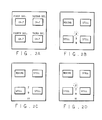
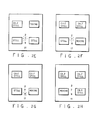
- Figures 2A-2H are screen status diagrams illustrating examples of operation of the system of Figure 1;
- Figure 3 is a flow chart illustrating an example of the overall operation of the system;
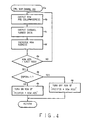
- Figure 4 is a flow chart illustrating one example of a procedure for displaying channel status; and
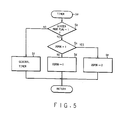
- Figure 5 is a flow chart illustrating one example of a procedure for flickering a skip channel on-screen-display (OSD).
- Referring now to Figure 1, a signal from a remote controller (not shown) is amplified by a pre-amplifier 17 and applied to a
microcomputer 10. Themicrocomputer 10 decodes the received signal to determine which key of the remote controller has been pressed. First andsecond tuners second tuner microcomputer 10. Data output from a data terminal DATA, of themicrocomputer 10 affects the channel to be selected. - Output terminals T3, T4 of the first and
second tuners input selectors input selectors input selectors microcomputer 10 to select one of the signals applied from the input terminals T1, T2 and the line L. Theinput selector 12 is used to select a main screen, while theinput selector 13 is used to select sub-screens. - The signals selected by the
input selectors unit 14 and a picture-in-picture (PIP)unit 11, respectively. - The Y/
C unit 14 is used to create the main screen. The signals selected for the main screen by theinput selector 12 will be a first screen image source from thefirst tuner 15 if a playback (PB) key is not input, and an image source from tape if the playback key (PB) is input. - The main screen and the sub-screen selected by the
input selectors PIP unit 11. The PIP screen generated under the control of signals from clock SCK, data DATA and strobe STB terminals of themicrocomputer 10 is applied into amixer 19. An On-Screen-Display (OSD) 18 displays characters under the control of signals from the clock SCK, data DATA and strobe STB terminals of themicrocomputer 10. The character data is sent to themixer 19 to be superimposed upon the screen. Themixer 19 superimposes the characters upon the screen to provide a video signal output. - The
PIP unit 11 is controlled by exchanging data in series with themicrocomputer 10. As is shown in Table 1 hereinbelow, if themicrocomputer 10 outputs the data (0000 0010), thePIP unit 11 performs a rotation function.
- Upon pressing a ROTATE key (for example, in a 4-PIP system), the microcomputer will stop strobing. To achieve this strobe-stop condition, the strobe data should be output in series to the
PIP unit 11 from themicrocomputer 10. To configure the PIP screen, it is necessary to press a SCREEN PROGRAM key, when the screen display has the normal condition illustrated in Figure 2A. - Thus, upon pressing the SCREEN PROGRAM key, strobing will be stopped and, as shown in the example of Figure 2B, a skip channel is displayed by the
OSD 18, such that the upper-most channel number flickers. Strobing transfers the position of the moving screen in a given direction, rotationally. Only one of the four sub-screens is a moving screen, while the others remain as still screens. The strobe-stop state is the state where the system remains in one of the strobing states, i.e., any one of the four sub-screens is a moving screen and the others are still screens. A skip channel represents a channel that is available for actual broadcasting. A memory which stores the skip channel numbers is called a skip memory. - As shown in Figure 2B, the upper-most channel numberflickers in the respective strobe-stop state. Thereafter, pressing a channel UP/DOWN key changes the channel number that is flickering. Upon pressing the channel UP/DOWN key for a lower channel when the
lower-most channel 9 is flickering,channel 2 will disappear and as, shown in Figure 2C,channel 11, the next channel in the skip memory, will be displayed. - The following is a description of how a screen display comprised of four channel-7 screens is changed to one comprised of
channels flickering channel 2 and is transferred to a second location (top right). As shown in Figure 2E, the first location is configured with thechannel 2 in still mode. - Thereafter, in order to configure the second location with
channel 7, executing a rotation, or pressing the ROTATE key after making thechannel 7 flicker by using the channel UP/DOWN key for a lower channel as shown in Figure 2E, results in the configuration of Figure 2F. - Configuring a third location (bottom right) with
channel 9 and a fourth location withchannel 11 is carried out in the same way as the configuration procedures for the first and second locations. The resulting screens are depicted in Figures 2G and 2H, respectively. - Pressing the SCREEN PROGRAM key to leave the screen program mode releases the strobe-stop. Then, the channels configured by the user will be displayed and the OSD display for the skip channel will disappear.
- The screen program function will now be described by referring to the flow diagram in Figure 3. At step 1 a, "1" is assigned to a screen mode flag and at
step 1 b, themicrocomputer 10 checks whether the SCREEN PROGRAM key is pressed. If it is pressed, strobing will be stopped and step 1c will be executed. Otherwise, thestep 1 b will be repeated. - At the
step 1c, themicrocomputer 10 checks for 4-PIP screen mode. If 4-PIP screen mode is selected,step 1d will be executed. Otherwise,step 1e will be executed. Atstep 1d, the rotation data will be output andstep 2a will be executed. The 4-PIP data will be output atstep 1e and the rotation data will be output atstep 1f; then thestep 2a will be executed. -
Step 2a calls the skip channel OSD andstep 2b checks whether the channel UP/DOWN key is pressed. If it is pressed, the skip memory pointer value will be increased by a designated value and thestep 2a will be performed again. If it is not pressed, whether the ROTATE key is pressed will be checked at step 2d. If the ROTATE key is pressed,step 2e will be executed or, otherwise, step 3a will be executed. The channel which is flickering on theskip channel OSD 18 is selected at thestep 2e and then step 2f will be performed. At thestep 2f, the rotation data is generated and thenstep 2a is executed again. - At the step 3a, whether the SCREEN PROGRAM key is pressed will be checked. If it is not pressed, the
step 2a will be executed again. Otherwise, it clears theskip channel OSD 18 atstep 3b and executesstep 3c. The strobe-stop condition that outputs the strobing data will be released at thestep 3c and then step 3d will be executed. At thestep 3d, the screen mode flag will be set to "0" to complete the procedure. - Figure 4 shows a flow diagram for indicating the channel on the screen, wherein the following steps will be executed upon calling the
skip channel OSD 18 at thestep 2a. Theskip channel OSD 18 will be called and the data for row address and column address will be output atstep 4b and then step 4c will be performed. Thestep 4c outputs the channel number data stored in the skip memory andstep 4d increases the row address. Then step 4e will be executed. At thestep 4e, whether the row address is the same as a last address will be checked. If it is not the same as the last address, thestep 4b will be executed again. If it is the last address,step 4f will be executed. Thestep 4f checks whether display-on flag DSPON is set to "1 ". If it is not "1",step 4h will be executed. If it is "1", step 4g will be performed. - At the step 4g, the line corresponding to the pointer value which is added with the row address will be turned off to return. At the
step 4h, the line corresponding to the pointer value plus the row address will be turned on to return to the main procedure. - Figure 5 shows a flow diagram to show the time for the skip channel flickering interval.
Step 5b checks whether the screen mode is "1" or not. If it is "1", step 5c will be executed. If not "1",step 5f will be performed. Thestep 5c checks whether the display-on flag DSPON is set to "1" or not. If it is not "1", the display-on flag DSPON is set to "1" atstep 5d and then returns. If it is "1", the display-on flag DSPON is set to "0" atstep 5e and then returns. At thestep 5f, the general timer operates for a predetermined period and then returns. - As described above, for each designated screen channel memorized on the PIP screen, the user directly configures the desired PIP screen using the skip channel OSD. Therefore, the user is provided with various PIP screens which may show different channels, rather than all the same one.
wherein said microcomputer is arranged to change the channel of a selected one of the sub-screens to a channel number displayed by the OSD unit.
Claims (15)
wherein said microcomputer (10) is arranged to change the channel of a selected one of the sub-screens to a channel number displayed by the OSD unit (18).
Applications Claiming Priority (2)
| Application Number | Priority Date | Filing Date | Title |
|---|---|---|---|
| KR1810188 | 1988-12-31 | ||
| KR1019880018101A KR920002049B1 (en) | 1988-12-31 | 1988-12-31 | Multi-screen execution method |
Publications (4)
| Publication Number | Publication Date |
|---|---|
| EP0377334A2 EP0377334A2 (en) | 1990-07-11 |
| EP0377334A3 EP0377334A3 (en) | 1991-04-24 |
| EP0377334B1 true EP0377334B1 (en) | 1995-06-21 |
| EP0377334B2 EP0377334B2 (en) | 1998-07-29 |
Family
ID=19281117
Family Applications (1)
| Application Number | Title | Priority Date | Filing Date |
|---|---|---|---|
| EP89313689A Expired - Lifetime EP0377334B2 (en) | 1988-12-31 | 1989-12-29 | Picture-in-picture systems |
Country Status (4)
| Country | Link |
|---|---|
| US (1) | US5045946A (en) |
| EP (1) | EP0377334B2 (en) |
| KR (1) | KR920002049B1 (en) |
| DE (1) | DE68923165T3 (en) |
Cited By (4)
| Publication number | Priority date | Publication date | Assignee | Title |
|---|---|---|---|---|
| US6181335B1 (en) | 1992-12-09 | 2001-01-30 | Discovery Communications, Inc. | Card for a set top terminal |
| US8095949B1 (en) | 1993-12-02 | 2012-01-10 | Adrea, LLC | Electronic book with restricted access features |
| US8548813B2 (en) | 1999-06-25 | 2013-10-01 | Adrea, LLC | Electronic book with voice emulation features |
| US9053640B1 (en) | 1993-12-02 | 2015-06-09 | Adrea, LLC | Interactive electronic book |
Families Citing this family (45)
| Publication number | Priority date | Publication date | Assignee | Title |
|---|---|---|---|---|
| IT1241338B (en) * | 1990-12-06 | 1994-01-10 | Sisvel Spa | PERFECTED RECEIVER OF TELETEXT TRANSMISSIONS |
| JPH04314278A (en) * | 1991-04-12 | 1992-11-05 | Sony Corp | Video signal receiver |
| KR930003720A (en) * | 1991-07-09 | 1993-02-24 | 강진구 | How to automatically discover PIP channels |
| JPH0575944A (en) * | 1991-09-10 | 1993-03-26 | Sony Corp | Television receiver |
| EP0536828A1 (en) * | 1991-10-07 | 1993-04-14 | Koninklijke Philips Electronics N.V. | Television receiver |
| US20020091850A1 (en) | 1992-10-23 | 2002-07-11 | Cybex Corporation | System and method for remote monitoring and operation of personal computers |
| US7849393B1 (en) | 1992-12-09 | 2010-12-07 | Discovery Communications, Inc. | Electronic book connection to world watch live |
| US7168084B1 (en) | 1992-12-09 | 2007-01-23 | Sedna Patent Services, Llc | Method and apparatus for targeting virtual objects |
| US7509270B1 (en) | 1992-12-09 | 2009-03-24 | Discovery Communications, Inc. | Electronic Book having electronic commerce features |
| US5659350A (en) | 1992-12-09 | 1997-08-19 | Discovery Communications, Inc. | Operations center for a television program packaging and delivery system |
| US7835989B1 (en) | 1992-12-09 | 2010-11-16 | Discovery Communications, Inc. | Electronic book alternative delivery systems |
| BR9307623A (en) | 1992-12-09 | 2000-05-16 | Discovery Communicat Inc | Upgrade module, hardware upgrade and process to feed the functionality of a decompression box and a top converter for receiver, top converter for upgradeable receiver for use in a cable television distribution system, top terminal for receiver , advanced, remote control unit for use with upper receiver terminal, interface system with program instructions, and process for upgrading an upper receiver converter for use in a cable television program delivery system. |
| US9286294B2 (en) | 1992-12-09 | 2016-03-15 | Comcast Ip Holdings I, Llc | Video and digital multimedia aggregator content suggestion engine |
| KR950008122B1 (en) * | 1992-12-17 | 1995-07-25 | 주식회사금성사 | Screen search method of television |
| KR950008124B1 (en) * | 1992-12-23 | 1995-07-25 | 주식회사금성사 | Channel automemory apparatus & method in pop tv |
| US7861166B1 (en) | 1993-12-02 | 2010-12-28 | Discovery Patent Holding, Llc | Resizing document pages to fit available hardware screens |
| US7865567B1 (en) | 1993-12-02 | 2011-01-04 | Discovery Patent Holdings, Llc | Virtual on-demand electronic book |
| IT1273150B (en) * | 1994-04-15 | 1997-07-04 | S E I Societa Elettronica Ital | RECEIVER OF TELEVISION SIGNALS WITH REMOTE CONTROL AND POSSIBILITY OF CONTEMPORARY VISUALIZATION OF A MULTIPLE OF IMAGES CORRESPONDING TO AS MANY RECEIVED SIGNALS |
| US6215467B1 (en) * | 1995-04-27 | 2001-04-10 | Canon Kabushiki Kaisha | Display control apparatus and method and display apparatus |
| US5721842A (en) | 1995-08-25 | 1998-02-24 | Apex Pc Solutions, Inc. | Interconnection system for viewing and controlling remotely connected computers with on-screen video overlay for controlling of the interconnection switch |
| US6480238B1 (en) * | 1996-10-16 | 2002-11-12 | Thomson Licensing S.A. | Apparatus and method for generating on-screen-display messages using field doubling |
| KR100225063B1 (en) * | 1996-10-17 | 1999-10-15 | 윤종용 | Multiple video displayer |
| US6429903B1 (en) | 1997-09-03 | 2002-08-06 | Colorgraphic Communications Corporation | Video adapter for supporting at least one television monitor |
| US6028643A (en) * | 1997-09-03 | 2000-02-22 | Colorgraphic Communications Corporation | Multiple-screen video adapter with television tuner |
| DE69935234T2 (en) | 1998-09-22 | 2007-11-08 | Avocent Huntsville Corp., Huntsville | SYSTEM FOR REMOTE ACCESS TO PERSONAL COMPUTER |
| US6519283B1 (en) | 1999-01-25 | 2003-02-11 | International Business Machines Corporation | Integrated video processing system having multiple video sources and implementing picture-in-picture with on-screen display graphics |
| US6753928B1 (en) | 1999-11-17 | 2004-06-22 | Thomson Licensing S.A. | Method and apparatus for providing feedback during programming of a television apparatus |
| JP2002246881A (en) * | 2001-02-16 | 2002-08-30 | Funai Electric Co Ltd | Channel selecting device for broadcasting receiver and broadcasting receiver having the same device |
| US7908628B2 (en) | 2001-08-03 | 2011-03-15 | Comcast Ip Holdings I, Llc | Video and digital multimedia aggregator content coding and formatting |
| US7793326B2 (en) | 2001-08-03 | 2010-09-07 | Comcast Ip Holdings I, Llc | Video and digital multimedia aggregator |
| KR100365839B1 (en) * | 2002-08-22 | 2002-12-31 | Huwell Technology Inc | System for real time service using interactive data communication and method thereof |
| US8869206B2 (en) | 2002-12-10 | 2014-10-21 | Lg Electronics Inc. | Digital television and channel editing method thereof |
| KR100518874B1 (en) * | 2002-12-10 | 2005-10-04 | 엘지전자 주식회사 | A digital tv and method for editing channel of the same |
| GB0229245D0 (en) * | 2002-12-13 | 2003-01-22 | Koninkl Philips Electronics Nv | Television display unit |
| KR101015412B1 (en) * | 2003-01-17 | 2011-02-22 | 톰슨 라이센싱 | Electronic apparatus generating video signals and process for generating video signals |
| KR100580174B1 (en) * | 2003-08-21 | 2006-05-16 | 삼성전자주식회사 | Rotatable display apparatus and method for adjusting display screen |
| JP2006067063A (en) * | 2004-08-25 | 2006-03-09 | Fujitsu Ltd | Switching device, electronic equipment, data transferring method and program for making computer execute the same method |
| JP4270130B2 (en) * | 2005-01-11 | 2009-05-27 | カシオ計算機株式会社 | Television receiver and control program therefor |
| KR100689474B1 (en) * | 2005-01-27 | 2007-03-08 | 삼성전자주식회사 | Transport Stream Receiving Apparatus For Multi-Screen and Its Control Method |
| US7532253B1 (en) * | 2005-07-26 | 2009-05-12 | Pixelworks, Inc. | Television channel change picture-in-picture circuit and method |
| KR100696723B1 (en) * | 2005-08-03 | 2007-03-20 | 경북대학교 산학협력단 | Pattern generator |
| KR101295567B1 (en) * | 2006-09-28 | 2013-08-12 | 엘지전자 주식회사 | Televisoin and method providing channel using it |
| US9210468B2 (en) * | 2011-03-22 | 2015-12-08 | Sony Corporation | System and method for effectively implementing a stroboscopic visual effect |
| JP2018533288A (en) * | 2015-09-23 | 2018-11-08 | ロヴィ ガイズ, インコーポレイテッド | System and method for detecting events in a program from multiple channels |
| US10158904B2 (en) | 2015-09-23 | 2018-12-18 | Rovi Guides, Inc. | Systems and methods to combine programming from multiple channels |
Family Cites Families (8)
| Publication number | Priority date | Publication date | Assignee | Title |
|---|---|---|---|---|
| JPS58196778A (en) * | 1982-05-11 | 1983-11-16 | Sony Corp | Television receiver of synthesizer system |
| JPH0748834B2 (en) * | 1986-11-04 | 1995-05-24 | 松下電器産業株式会社 | Video signal processor |
| US4897727A (en) * | 1988-05-09 | 1990-01-30 | Thomson Consumer Electronics, Inc. | Television tuning system allowing rapid response to user initiated commands |
| DE3920119A1 (en) * | 1988-06-20 | 1989-12-21 | Samsung Electronics Co Ltd | Multi-channel editor of the menu type |
| US4918531A (en) * | 1988-10-25 | 1990-04-17 | Thomson Consumer Electronics, Inc. | Commercial message timer |
| US4959719A (en) * | 1988-12-21 | 1990-09-25 | North American Philips Corporation | Picture-in-picture television receiver control |
| US4959720A (en) * | 1989-04-06 | 1990-09-25 | Rca Licensing Corporation | Tuner control apparatus having tune-by-label capability |
| US4996597A (en) * | 1989-04-20 | 1991-02-26 | Rca Licensing Corporation | User programmable switching arrangement |
-
1988
- 1988-12-31 KR KR1019880018101A patent/KR920002049B1/en not_active IP Right Cessation
-
1989
- 1989-11-21 US US07/439,323 patent/US5045946A/en not_active Expired - Lifetime
- 1989-12-29 DE DE68923165T patent/DE68923165T3/en not_active Expired - Fee Related
- 1989-12-29 EP EP89313689A patent/EP0377334B2/en not_active Expired - Lifetime
Cited By (4)
| Publication number | Priority date | Publication date | Assignee | Title |
|---|---|---|---|---|
| US6181335B1 (en) | 1992-12-09 | 2001-01-30 | Discovery Communications, Inc. | Card for a set top terminal |
| US8095949B1 (en) | 1993-12-02 | 2012-01-10 | Adrea, LLC | Electronic book with restricted access features |
| US9053640B1 (en) | 1993-12-02 | 2015-06-09 | Adrea, LLC | Interactive electronic book |
| US8548813B2 (en) | 1999-06-25 | 2013-10-01 | Adrea, LLC | Electronic book with voice emulation features |
Also Published As
| Publication number | Publication date |
|---|---|
| DE68923165T2 (en) | 1996-02-08 |
| EP0377334A2 (en) | 1990-07-11 |
| KR920002049B1 (en) | 1992-03-10 |
| KR900011269A (en) | 1990-07-11 |
| US5045946A (en) | 1991-09-03 |
| EP0377334B2 (en) | 1998-07-29 |
| DE68923165T3 (en) | 1999-02-25 |
| DE68923165D1 (en) | 1995-07-27 |
| EP0377334A3 (en) | 1991-04-24 |
Similar Documents
| Publication | Publication Date | Title |
|---|---|---|
| EP0377334B1 (en) | Picture-in-picture systems | |
| US4959719A (en) | Picture-in-picture television receiver control | |
| US5867227A (en) | Television receiver | |
| US5398074A (en) | Programmable picture-outside-picture display | |
| EP0550911B1 (en) | Programmable picture-outside-picture display | |
| KR930007255A (en) | Television receiver | |
| US5506628A (en) | Menu-type multi-channel system having a page up/down mode feature | |
| US5093726A (en) | Multi-type multi-channel selector | |
| JPH09182033A (en) | System for freezing closed caption data | |
| JP3008416B2 (en) | Video output device | |
| JP2751270B2 (en) | AVTC system | |
| JP2562211B2 (en) | Multi-screen execution method | |
| JPH0296486A (en) | Multichannel system of menu system facilitating page up/down | |
| KR100561386B1 (en) | System for interfacing external apparatus sources connected to a television | |
| JPH1051709A (en) | Television receiver | |
| JP2001257970A (en) | Magnetic recording and reproducing device | |
| JPH0832892A (en) | Display device | |
| KR960002506B1 (en) | Mode selecting apparatus using tv screen | |
| JPH04334180A (en) | Reserved picture-recording notice display unit | |
| JPH04132475A (en) | Method and apparatus for on-screen display | |
| JPH06274139A (en) | Window screen selecting method | |
| KR100207622B1 (en) | Multiple input selector unit in video printer | |
| JPH08335857A (en) | Channel search device | |
| KR0134333B1 (en) | Cross talk removal apparatus of pip | |
| KR19990019107A (en) | How to display program information |
Legal Events
| Date | Code | Title | Description |
|---|---|---|---|
| PUAI | Public reference made under article 153(3) epc to a published international application that has entered the european phase |
Free format text: ORIGINAL CODE: 0009012 |
|
| AK | Designated contracting states |
Kind code of ref document: A2 Designated state(s): DE FR GB NL |
|
| PUAL | Search report despatched |
Free format text: ORIGINAL CODE: 0009013 |
|
| AK | Designated contracting states |
Kind code of ref document: A3 Designated state(s): DE FR GB NL |
|
| 17P | Request for examination filed |
Effective date: 19910503 |
|
| 17Q | First examination report despatched |
Effective date: 19930408 |
|
| GRAA | (expected) grant |
Free format text: ORIGINAL CODE: 0009210 |
|
| AK | Designated contracting states |
Kind code of ref document: B1 Designated state(s): DE FR GB NL |
|
| ET | Fr: translation filed | ||
| REF | Corresponds to: |
Ref document number: 68923165 Country of ref document: DE Date of ref document: 19950727 |
|
| PLBQ | Unpublished change to opponent data |
Free format text: ORIGINAL CODE: EPIDOS OPPO |
|
| PLBI | Opposition filed |
Free format text: ORIGINAL CODE: 0009260 |
|
| PLBF | Reply of patent proprietor to notice(s) of opposition |
Free format text: ORIGINAL CODE: EPIDOS OBSO |
|
| 26 | Opposition filed |
Opponent name: INTERESSENGEMEINSCHAFT FUER RUNDFUNKSCHUTZRECHTE G Effective date: 19960321 |
|
| NLR1 | Nl: opposition has been filed with the epo |
Opponent name: INTERESSENGEMEINSCHAFT FUER RUNDFUNKSCHUTZRECHTE G |
|
| PLBF | Reply of patent proprietor to notice(s) of opposition |
Free format text: ORIGINAL CODE: EPIDOS OBSO |
|
| PLBF | Reply of patent proprietor to notice(s) of opposition |
Free format text: ORIGINAL CODE: EPIDOS OBSO |
|
| PLAW | Interlocutory decision in opposition |
Free format text: ORIGINAL CODE: EPIDOS IDOP |
|
| PLAW | Interlocutory decision in opposition |
Free format text: ORIGINAL CODE: EPIDOS IDOP |
|
| PUAH | Patent maintained in amended form |
Free format text: ORIGINAL CODE: 0009272 |
|
| STAA | Information on the status of an ep patent application or granted ep patent |
Free format text: STATUS: PATENT MAINTAINED AS AMENDED |
|
| 27A | Patent maintained in amended form |
Effective date: 19980729 |
|
| AK | Designated contracting states |
Kind code of ref document: B2 Designated state(s): DE FR GB NL |
|
| NLR2 | Nl: decision of opposition | ||
| NLR3 | Nl: receipt of modified translations in the netherlands language after an opposition procedure | ||
| ET3 | Fr: translation filed ** decision concerning opposition | ||
| REG | Reference to a national code |
Ref country code: GB Ref legal event code: IF02 |
|
| PGFP | Annual fee paid to national office [announced via postgrant information from national office to epo] |
Ref country code: NL Payment date: 20071203 Year of fee payment: 19 |
|
| PGFP | Annual fee paid to national office [announced via postgrant information from national office to epo] |
Ref country code: GB Payment date: 20071227 Year of fee payment: 19 Ref country code: FR Payment date: 20071210 Year of fee payment: 19 |
|
| PGFP | Annual fee paid to national office [announced via postgrant information from national office to epo] |
Ref country code: DE Payment date: 20071231 Year of fee payment: 19 |
|
| GBPC | Gb: european patent ceased through non-payment of renewal fee |
Effective date: 20081229 |
|
| NLV4 | Nl: lapsed or anulled due to non-payment of the annual fee |
Effective date: 20090701 |
|
| REG | Reference to a national code |
Ref country code: FR Ref legal event code: ST Effective date: 20090831 |
|
| PG25 | Lapsed in a contracting state [announced via postgrant information from national office to epo] |
Ref country code: DE Free format text: LAPSE BECAUSE OF NON-PAYMENT OF DUE FEES Effective date: 20090701 |
|
| PG25 | Lapsed in a contracting state [announced via postgrant information from national office to epo] |
Ref country code: NL Free format text: LAPSE BECAUSE OF NON-PAYMENT OF DUE FEES Effective date: 20090701 Ref country code: GB Free format text: LAPSE BECAUSE OF NON-PAYMENT OF DUE FEES Effective date: 20081229 |
|
| PG25 | Lapsed in a contracting state [announced via postgrant information from national office to epo] |
Ref country code: FR Free format text: LAPSE BECAUSE OF NON-PAYMENT OF DUE FEES Effective date: 20081231 |