EP0380366A2 - Substrate for recording head and recording head - Google Patents
Substrate for recording head and recording head Download PDFInfo
- Publication number
- EP0380366A2 EP0380366A2 EP90300854A EP90300854A EP0380366A2 EP 0380366 A2 EP0380366 A2 EP 0380366A2 EP 90300854 A EP90300854 A EP 90300854A EP 90300854 A EP90300854 A EP 90300854A EP 0380366 A2 EP0380366 A2 EP 0380366A2
- Authority
- EP
- European Patent Office
- Prior art keywords
- substrate
- recording head
- liquid
- recording
- discharging
- Prior art date
- Legal status (The legal status is an assumption and is not a legal conclusion. Google has not performed a legal analysis and makes no representation as to the accuracy of the status listed.)
- Granted
Links
- 239000000758 substrate Substances 0.000 title claims abstract description 33
- 239000007788 liquid Substances 0.000 claims abstract description 64
- 238000007599 discharging Methods 0.000 claims abstract description 36
- 239000011368 organic material Substances 0.000 claims abstract description 9
- 239000000463 material Substances 0.000 claims description 13
- 239000004642 Polyimide Substances 0.000 claims description 10
- 229920001721 polyimide Polymers 0.000 claims description 10
- 239000011810 insulating material Substances 0.000 claims description 6
- 229910052719 titanium Inorganic materials 0.000 claims description 5
- 229910052802 copper Inorganic materials 0.000 claims description 4
- 229910052804 chromium Inorganic materials 0.000 claims description 3
- 229910052759 nickel Inorganic materials 0.000 claims description 3
- 229910052737 gold Inorganic materials 0.000 claims description 2
- 229910052718 tin Inorganic materials 0.000 claims description 2
- 238000010438 heat treatment Methods 0.000 claims 6
- PXHVJJICTQNCMI-UHFFFAOYSA-N Nickel Chemical compound [Ni] PXHVJJICTQNCMI-UHFFFAOYSA-N 0.000 claims 3
- 239000011651 chromium Substances 0.000 claims 2
- 239000010949 copper Substances 0.000 claims 2
- 239000010931 gold Substances 0.000 claims 2
- 239000010936 titanium Substances 0.000 claims 2
- VYZAMTAEIAYCRO-UHFFFAOYSA-N Chromium Chemical compound [Cr] VYZAMTAEIAYCRO-UHFFFAOYSA-N 0.000 claims 1
- RYGMFSIKBFXOCR-UHFFFAOYSA-N Copper Chemical compound [Cu] RYGMFSIKBFXOCR-UHFFFAOYSA-N 0.000 claims 1
- ATJFFYVFTNAWJD-UHFFFAOYSA-N Tin Chemical compound [Sn] ATJFFYVFTNAWJD-UHFFFAOYSA-N 0.000 claims 1
- RTAQQCXQSZGOHL-UHFFFAOYSA-N Titanium Chemical compound [Ti] RTAQQCXQSZGOHL-UHFFFAOYSA-N 0.000 claims 1
- PCHJSUWPFVWCPO-UHFFFAOYSA-N gold Chemical compound [Au] PCHJSUWPFVWCPO-UHFFFAOYSA-N 0.000 claims 1
- 239000010410 layer Substances 0.000 description 47
- VYPSYNLAJGMNEJ-UHFFFAOYSA-N Silicium dioxide Chemical compound O=[Si]=O VYPSYNLAJGMNEJ-UHFFFAOYSA-N 0.000 description 12
- 229910052681 coesite Inorganic materials 0.000 description 6
- 229910052906 cristobalite Inorganic materials 0.000 description 6
- 238000000059 patterning Methods 0.000 description 6
- 230000001681 protective effect Effects 0.000 description 6
- 239000000377 silicon dioxide Substances 0.000 description 6
- 235000012239 silicon dioxide Nutrition 0.000 description 6
- 229910052682 stishovite Inorganic materials 0.000 description 6
- 229910052905 tridymite Inorganic materials 0.000 description 6
- 230000015572 biosynthetic process Effects 0.000 description 5
- 230000003647 oxidation Effects 0.000 description 4
- 238000007254 oxidation reaction Methods 0.000 description 4
- 229910003862 HfB2 Inorganic materials 0.000 description 3
- 238000000280 densification Methods 0.000 description 3
- 238000002360 preparation method Methods 0.000 description 3
- 229910052782 aluminium Inorganic materials 0.000 description 2
- 238000004519 manufacturing process Methods 0.000 description 2
- 238000000034 method Methods 0.000 description 2
- 239000011241 protective layer Substances 0.000 description 2
- 238000004544 sputter deposition Methods 0.000 description 2
- 229910004490 TaAl Inorganic materials 0.000 description 1
- 239000000470 constituent Substances 0.000 description 1
- 238000005530 etching Methods 0.000 description 1
- 239000011521 glass Substances 0.000 description 1
- 239000011229 interlayer Substances 0.000 description 1
- 230000002085 persistent effect Effects 0.000 description 1
- 238000007747 plating Methods 0.000 description 1
- 239000004065 semiconductor Substances 0.000 description 1
- 229910052710 silicon Inorganic materials 0.000 description 1
- 239000010703 silicon Substances 0.000 description 1
- 238000001029 thermal curing Methods 0.000 description 1
Images


Classifications
-
- B—PERFORMING OPERATIONS; TRANSPORTING
- B41—PRINTING; LINING MACHINES; TYPEWRITERS; STAMPS
- B41J—TYPEWRITERS; SELECTIVE PRINTING MECHANISMS, i.e. MECHANISMS PRINTING OTHERWISE THAN FROM A FORME; CORRECTION OF TYPOGRAPHICAL ERRORS
- B41J2/00—Typewriters or selective printing mechanisms characterised by the printing or marking process for which they are designed
- B41J2/005—Typewriters or selective printing mechanisms characterised by the printing or marking process for which they are designed characterised by bringing liquid or particles selectively into contact with a printing material
- B41J2/01—Ink jet
- B41J2/135—Nozzles
- B41J2/14—Structure thereof only for on-demand ink jet heads
- B41J2/14016—Structure of bubble jet print heads
- B41J2/14088—Structure of heating means
- B41J2/14112—Resistive element
- B41J2/14129—Layer structure
-
- B—PERFORMING OPERATIONS; TRANSPORTING
- B41—PRINTING; LINING MACHINES; TYPEWRITERS; STAMPS
- B41J—TYPEWRITERS; SELECTIVE PRINTING MECHANISMS, i.e. MECHANISMS PRINTING OTHERWISE THAN FROM A FORME; CORRECTION OF TYPOGRAPHICAL ERRORS
- B41J2/00—Typewriters or selective printing mechanisms characterised by the printing or marking process for which they are designed
- B41J2/005—Typewriters or selective printing mechanisms characterised by the printing or marking process for which they are designed characterised by bringing liquid or particles selectively into contact with a printing material
- B41J2/01—Ink jet
- B41J2/135—Nozzles
- B41J2/16—Production of nozzles
- B41J2/1601—Production of bubble jet print heads
- B41J2/1603—Production of bubble jet print heads of the front shooter type
-
- B—PERFORMING OPERATIONS; TRANSPORTING
- B41—PRINTING; LINING MACHINES; TYPEWRITERS; STAMPS
- B41J—TYPEWRITERS; SELECTIVE PRINTING MECHANISMS, i.e. MECHANISMS PRINTING OTHERWISE THAN FROM A FORME; CORRECTION OF TYPOGRAPHICAL ERRORS
- B41J2/00—Typewriters or selective printing mechanisms characterised by the printing or marking process for which they are designed
- B41J2/005—Typewriters or selective printing mechanisms characterised by the printing or marking process for which they are designed characterised by bringing liquid or particles selectively into contact with a printing material
- B41J2/01—Ink jet
- B41J2/135—Nozzles
- B41J2/16—Production of nozzles
- B41J2/1601—Production of bubble jet print heads
- B41J2/1604—Production of bubble jet print heads of the edge shooter type
-
- B—PERFORMING OPERATIONS; TRANSPORTING
- B41—PRINTING; LINING MACHINES; TYPEWRITERS; STAMPS
- B41J—TYPEWRITERS; SELECTIVE PRINTING MECHANISMS, i.e. MECHANISMS PRINTING OTHERWISE THAN FROM A FORME; CORRECTION OF TYPOGRAPHICAL ERRORS
- B41J2/00—Typewriters or selective printing mechanisms characterised by the printing or marking process for which they are designed
- B41J2/005—Typewriters or selective printing mechanisms characterised by the printing or marking process for which they are designed characterised by bringing liquid or particles selectively into contact with a printing material
- B41J2/01—Ink jet
- B41J2/135—Nozzles
- B41J2/16—Production of nozzles
- B41J2/1621—Manufacturing processes
- B41J2/1623—Manufacturing processes bonding and adhesion
-
- B—PERFORMING OPERATIONS; TRANSPORTING
- B41—PRINTING; LINING MACHINES; TYPEWRITERS; STAMPS
- B41J—TYPEWRITERS; SELECTIVE PRINTING MECHANISMS, i.e. MECHANISMS PRINTING OTHERWISE THAN FROM A FORME; CORRECTION OF TYPOGRAPHICAL ERRORS
- B41J2/00—Typewriters or selective printing mechanisms characterised by the printing or marking process for which they are designed
- B41J2/005—Typewriters or selective printing mechanisms characterised by the printing or marking process for which they are designed characterised by bringing liquid or particles selectively into contact with a printing material
- B41J2/01—Ink jet
- B41J2/135—Nozzles
- B41J2/16—Production of nozzles
- B41J2/1621—Manufacturing processes
- B41J2/1631—Manufacturing processes photolithography
-
- B—PERFORMING OPERATIONS; TRANSPORTING
- B41—PRINTING; LINING MACHINES; TYPEWRITERS; STAMPS
- B41J—TYPEWRITERS; SELECTIVE PRINTING MECHANISMS, i.e. MECHANISMS PRINTING OTHERWISE THAN FROM A FORME; CORRECTION OF TYPOGRAPHICAL ERRORS
- B41J2/00—Typewriters or selective printing mechanisms characterised by the printing or marking process for which they are designed
- B41J2/005—Typewriters or selective printing mechanisms characterised by the printing or marking process for which they are designed characterised by bringing liquid or particles selectively into contact with a printing material
- B41J2/01—Ink jet
- B41J2/135—Nozzles
- B41J2/16—Production of nozzles
- B41J2/1621—Manufacturing processes
- B41J2/164—Manufacturing processes thin film formation
- B41J2/1643—Manufacturing processes thin film formation thin film formation by plating
-
- B—PERFORMING OPERATIONS; TRANSPORTING
- B41—PRINTING; LINING MACHINES; TYPEWRITERS; STAMPS
- B41J—TYPEWRITERS; SELECTIVE PRINTING MECHANISMS, i.e. MECHANISMS PRINTING OTHERWISE THAN FROM A FORME; CORRECTION OF TYPOGRAPHICAL ERRORS
- B41J2/00—Typewriters or selective printing mechanisms characterised by the printing or marking process for which they are designed
- B41J2/005—Typewriters or selective printing mechanisms characterised by the printing or marking process for which they are designed characterised by bringing liquid or particles selectively into contact with a printing material
- B41J2/01—Ink jet
- B41J2/135—Nozzles
- B41J2/16—Production of nozzles
- B41J2/1621—Manufacturing processes
- B41J2/164—Manufacturing processes thin film formation
- B41J2/1646—Manufacturing processes thin film formation thin film formation by sputtering
Definitions
- This invention relates to a recording device such as output printers of copying device, word processor, facsimile, video, computer, etc. and a substrate for recording head and a recording head applicable thereto.
- a recording head and a recording device to which the liquid jet recording method which performs recording by discharging liquid for recording through discharging port is applicable.
- FIG. 1A is a schematic plan view of the substrate for recording head.
- Fig. 1B is a schematic sectional view of the recording head along the line B-B′ in Fig. 1A.
- the on-demand type recording head of the prior art has an electrode heat converter which generates heat energy to be utilized for discharging liquid (ink) by formation of a heat generating resistance layer 1 comprising HfB2, TaAl, etc. and an electroconductive layer 2 for formation of electrodes comprising Al, etc. arranged at predetermined intervals formed on a substrate 11 comprising a semiconductor such as silicon or an insulating material such as glass, etc., and on the heat generaing portion 1a of the electricity-heat converter are formed a discharging port and a liquid channel communicated thereto. And, a plurality of discharging ports are provided at a ratio of 8 or more per 1 mm for the purpose of high resolution recording, and electricity-heat converters are arranged at high density so as to correspond thereto.
- the liquid supplied from a liquid vessel not shown is supplied into the common liquid chamber as a part of liquid channel, and further fills the parts such as heat-acting portions, etc. corresponding respectively to the discharging ports of the liquid channels with liquid.
- Recording by way of liquid jetting generates bubbles by causing the state of change in the liquid on the heat-generating portion 1a in the heat acting portion by the heat energy generated from the heat-generating portion 1a by applying recording signals on the electrodes, thereby discharging liquid through the pressure of volume expansion of the bubbles to form flying liquid droplets.
- HfB2 film 1 as the heat-generating resistance layer for formation of an electricity-heat converter and Al as the electrode 2 are formed by sputtering, etc. and then subjected to patterning.
- SiO2 as the oxidation resistant film 3 for the electricity-heat converter and Ta as the cavitation resistant film 4 are formed by sputtering, etc. and subjected to patterning.
- a photosensitive polyimide is coated as the ink resistant film 5 and subjected to patterning.
- a ceiling plate 14 having a wall portion for sectionalizing the common liquid chamber 12 and individual liquid chambers 13 as the liquid channels for the recording liquid is plastered and a wiring connected to the driving circuit for supplying electrical signals is electrically connected (not shown) to prepare a liquid jet recording head.
- the present invention has been accomplished in view of the technical task as described above.
- An object of the present invention is to provide a recording heads improved in durability, which can obtain high resolution and has persistent good discharging state.
- Another object of the present invention is to provide a recording head which can improve the yield in production, is small in size and inexpensive.
- Still another object of the present invention is to provide a substrate for recording head, comprising an electricity-heat converter capable of generating heat energy for discharging liquid by causing the state change of liquid for recording by heat to occur and a wiring which is sandwiched on both sides between insulating layers comprising an organic material and connected electrically to said electricity-heat converter through at least one contact portion formed at said insulating layer.
- Still another object of the present invention is to provide a recording head, comprising: a liquid discharging portion having a discharging port for discharging liquid; and a substrate having an electricity-heat converter capable of generating heat energy for discharging liquid by causing the state change of liquid for recording by heat to occur existing within said liquid discharging portion and a wiring which is sandwiched on both sides between insulating layers comprising an organic material and connected electrically to said electricity-heat converter through at least one contact portion formed at said insulating layer.
- Still another object of the present invention is to provide a recording device, comprising: a liquid discharging portion having a discharging port for discharging liquid; a recording means including a substrate having an electricity-heat converter capable of generating heat energy for discharging liquid by causing the state change of liquid for recording by heat to occur existing within said liquid discharging portion, and a wiring which is sandwiched on both sides between insulating layers comprising an organic material and connected electrically to said electricity-heat converter through at least one contact portion formed at said insulating layer; a signal supplying means for supplying recording signals to said eletricity-heat converter; and a conveying means for conveying recording medium.
- Still another object of the present invention is to enable placement of a wiring connected to the common electrode with greater thickness and/or width than electrode into the (common) liquid chamber b use of organic materials above and beneath the electroconductive layers as a part of the wiring portion electrical connected to the electrodes, whereby the length of the common electrode can be made shorter to great extent. Accordingly, the electrodes can be made shorter, whereby generation of short circuit and wire breaking can be extremely reduced.
- Fig. 1A is a schematic plan view showing the recording head substrate of a prior art example
- Fig. 1B is a schematic sectional view of the recording head along the line B-B′ in Fig. 1A;
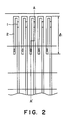
- Fig. 2 is a schematic plan view showing the recording head according to tee present invention.
- Fig. 3 is a schematic sectional view of the recording head along the line A-A′ in Fig. 2;
- Fig. 4 is a schematic perspective view of the recording head according to the present invention.
- Fig. 5 is a schematic illustration of the liquid jet recording device according of the present invention.
- Fig. 6 is a schematic perspective view of the recording head according to another embodiment of the present invention.
- Fig. 2 is a schematic plan view of the substrate of the recording head according to the present invention
- Fig. 3 is a schematic sectional view of the recording head along the line A-A′ in Fig. 2.
- a HfB2 layer as the heat generaing layer 1 and an Al layer as the electrode 2 of the electricity-heat converter for forming an electricity-heat member, and a first layer wiring is formed.
- An SiO2 layer as the oxidation resistant protective film 2 of the electricity-heat converter and a Ta layer as the cavitation resistant protective film 4 are formed.
- As the ink resistant protective film 5, a photosensitive polyimide 5 is coated.
- a part of the wiring portion as the second electroconductive wiring consists of multiple layers with different materials, and the uppermost layer 6 as the second elecroconductive layer 6 and the lowest layer 8 comprise the same material so as to sandwich the first electroconductive layer 7 above and beneath thereof.
- 6 is Ti layer, 7 Cu layer and 8 Ti layer.
- the protective layer 9 comprising an organic material
- a photosensitive polyimide For formation of plated electrodes by etching of Ti of the second electroconductive layer, Cu is exposed and Cu of higher conductivity is formed as the external common electrode 10.
- the heat generating resistance layer 1 and the electrode 2 are terminated respectively within the liquid chamber 12, and a SiO2 layer 3 and a photosensitive polimide 5 are arranged thereon.
- the polyimide 5 is formed and the second opening with smaller size than the first opening is formed by patterning.
- the SiO2 is covered at the end portion with the thru-hole portion.
- Ti layer 7, Cu layer 8 and Ti layer 9 are successively formed, patterned and finally the photosensitive polyimide 9 is formed so as to cover over these to constitute a connecting portion.
- a ceiling plate 14 is plastered having the grooves for the common liquid chamber 12 and the individual liquid channels 13 formed thereon on the substrate, and the wiring for connection to the main device side is electrically connected to constitute the liquid jet recording head 15 (Fig. 4).
- 16 is discharging port
- 17 is liquid channel wall
- 18 is port for supplying recording liquid.
- Ti, Cu and Ti forming the second layer wiring have respectively the following functions.
- Ti which constitutes the lowest layer 6 as the second electroconductive layer has good adhesion to the photosensitive polyimide which constitutes the ink resistant protective film 5.
- other than Ti, Cr, etc. may be available.
- Cu which constituted the intermediate layer 7 as the first electroconductive layer enhances the conductivity of the second layer wiring, serving as the plating subbing layer during preparation of the external common electrode 10, and here, other than Cu, Ni, Au, Sn, etc. may be suitably available.
- Ti which constitutes the upperpose layer 8 which is the second electroconductive layer has good adhesion to the photosensitive polyimide constituting the protective film 9 of the second layer wiring, and also at the same time functions as the oxidation resistant protective film for preventing oxidation of Cu which is one of the constituent materials during thermal curing in the preparation steps of the photosensitive polyimide.
- other than Ti, Cr, etc. may be preferably available.
- the liquid recording head 15 as described above is mounted on the carriage 19 as shown in Fig. 5, to be used for the liquid jet recording device.
- the recording head is scanned along the shaft 21 by means of the wire 20 for transmitting the driving force.
- the recording paper 22 as the recording medium is conveyed by the paper delivery roller 24 in contact with the conveying means, namely the platen 23. 25 is a discharging restoration system.
- the present invention is also applicable to the type which performs discharging in the direction crossing with the heat-generating surface as shown in Fig. 6.
- This comprises an orifice plate 26 having a discharging orifice 16 and a liquid channel wall 17 in combination on a heater substrate 11, and 18 shows the supplying inlet of recording liquid.
- the recording head of the present invention can accomplish miniaturization, higher densification, and therefore can be used suitably for the type which is provided integrally with a liquid vessel and made detachable relative to the carriage.
- the present invention can be preferably applied to the full-line type wherein some hundred to some thousand electricity-heat converters are arranged at a high density of 8 or more per 1 mm, whereby cost down to great extent can be expected.
- the common electrode wiring can be placed into the (common) liqid chamber, and the length of the electrodes wired at higher density can be made shorter, whereby the generation ratios of short circuit and wire breaking can be extremely reduced to further improve the yield.
Landscapes
- Engineering & Computer Science (AREA)
- Manufacturing & Machinery (AREA)
- Particle Formation And Scattering Control In Inkjet Printers (AREA)
- Manufacturing Of Printed Wiring (AREA)
- Accessory Devices And Overall Control Thereof (AREA)
Abstract
Description
- This invention relates to a recording device such as output printers of copying device, word processor, facsimile, video, computer, etc. and a substrate for recording head and a recording head applicable thereto.
- More particularly, it relates to a recording head and a recording device to which the liquid jet recording method which performs recording by discharging liquid for recording through discharging port is applicable.
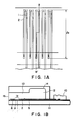
- An example of liquid jet recording head of the prior art is shown in Fig. 1A and 1B. Fig. 1A is a schematic plan view of the substrate for recording head. Fig. 1B is a schematic sectional view of the recording head along the line B-B′ in Fig. 1A.
- The on-demand type recording head of the prior art has an electrode heat converter which generates heat energy to be utilized for discharging liquid (ink) by formation of a heat generating resistance layer 1 comprising HfB₂, TaAl, etc. and an
electroconductive layer 2 for formation of electrodes comprising Al, etc. arranged at predetermined intervals formed on a substrate 11 comprising a semiconductor such as silicon or an insulating material such as glass, etc., and on the heat generaing portion 1a of the electricity-heat converter are formed a discharging port and a liquid channel communicated thereto. And, a plurality of discharging ports are provided at a ratio of 8 or more per 1 mm for the purpose of high resolution recording, and electricity-heat converters are arranged at high density so as to correspond thereto. - Here, 3, 4 and 5 are protective layers.
- The liquid supplied from a liquid vessel not shown is supplied into the common liquid chamber as a part of liquid channel, and further fills the parts such as heat-acting portions, etc. corresponding respectively to the discharging ports of the liquid channels with liquid.
- Recording by way of liquid jetting generates bubbles by causing the state of change in the liquid on the heat-generating portion 1a in the heat acting portion by the heat energy generated from the heat-generating portion 1a by applying recording signals on the electrodes, thereby discharging liquid through the pressure of volume expansion of the bubbles to form flying liquid droplets.
- The method for preparation of such recording head of the prior art is to be described.
- First, as HfB₂ film 1 as the heat-generating resistance layer for formation of an electricity-heat converter and Al as the
electrode 2 are formed by sputtering, etc. and then subjected to patterning. - Next, SiO₂ as the oxidation resistant film 3 for the electricity-heat converter and Ta as the cavitation
resistant film 4 are formed by sputtering, etc. and subjected to patterning. - And, a photosensitive polyimide is coated as the ink
resistant film 5 and subjected to patterning. - Further, Al, Ni and Cu of the the second layer are subjected to film forming patterning, and Cu is plated to about 10 µm for increasing conductivity to make a
common electrode 10. Here, SiO₂ represented by the symbol 3 which the layer beneath thecommon electrode 10 and the photosensitive polyimide represented by thesymbol 5 serve as the interlayer insulating layer. - Then, a
ceiling plate 14 having a wall portion for sectionalizing the commonliquid chamber 12 and individualliquid chambers 13 as the liquid channels for the recording liquid is plastered and a wiring connected to the driving circuit for supplying electrical signals is electrically connected (not shown) to prepare a liquid jet recording head. - However, in the above prior art example, since the
common electrode 10 exists externally of the ceiling plate 14 (namely outside the liquid channel of the recording head), the length of theelectrode 2 on the common electrode side is required to be ℓ₂ as shown in Fig. 1A, whereby a considerable length of high density wiring is required at the electrode. For this reason, other than the shortcomings in production such as lowered yield caused by short circuit, wire breaking, etc., short circuit or wire wiring sometimes occurred similarly when driving is performed by passing great current, whereby durability of the recording head was lowered. - The present invention has been accomplished in view of the technical task as described above.
- An object of the present invention is to provide a recording heads improved in durability, which can obtain high resolution and has persistent good discharging state.
- Another object of the present invention is to provide a recording head which can improve the yield in production, is small in size and inexpensive.
- Still another object of the present invention is to provide a substrate for recording head, comprising an electricity-heat converter capable of generating heat energy for discharging liquid by causing the state change of liquid for recording by heat to occur and a wiring which is sandwiched on both sides between insulating layers comprising an organic material and connected electrically to said electricity-heat converter through at least one contact portion formed at said insulating layer.
- Still another object of the present invention is to provide a recording head, comprising:
a liquid discharging portion having a discharging port for discharging liquid; and
a substrate having an electricity-heat converter capable of generating heat energy for discharging liquid by causing the state change of liquid for recording by heat to occur existing within said liquid discharging portion and a wiring which is sandwiched on both sides between insulating layers comprising an organic material and connected electrically to said electricity-heat converter through at least one contact portion formed at said insulating layer. - Still another object of the present invention is to provide a recording device, comprising:
a liquid discharging portion having a discharging port for discharging liquid;
a recording means including a substrate having an electricity-heat converter capable of generating heat energy for discharging liquid by causing the state change of liquid for recording by heat to occur existing within said liquid discharging portion, and a wiring which is sandwiched on both sides between insulating layers comprising an organic material and connected electrically to said electricity-heat converter through at least one contact portion formed at said insulating layer;
a signal supplying means for supplying recording signals to said eletricity-heat converter; and
a conveying means for conveying recording medium. - Still another object of the present invention is to enable placement of a wiring connected to the common electrode with greater thickness and/or width than electrode into the (common) liquid chamber b use of organic materials above and beneath the electroconductive layers as a part of the wiring portion electrical connected to the electrodes, whereby the length of the common electrode can be made shorter to great extent. Accordingly, the electrodes can be made shorter, whereby generation of short circuit and wire breaking can be extremely reduced.
- Also, it becomes very easy to provide the common wiring in the liquid chamber, whereby higher densification and miniaturization of the recording head are rendered possible.
- Fig. 1A is a schematic plan view showing the recording head substrate of a prior art example;
- Fig. 1B is a schematic sectional view of the recording head along the line B-B′ in Fig. 1A;
- Fig. 2 is a schematic plan view showing the recording head according to tee present invention;
- Fig. 3 is a schematic sectional view of the recording head along the line A-A′ in Fig. 2;
- Fig. 4 is a schematic perspective view of the recording head according to the present invention.
- Fig. 5 is a schematic illustration of the liquid jet recording device according of the present invention;
- Fig. 6 is a schematic perspective view of the recording head according to another embodiment of the present invention.
- Referring now to the drawings, the embodiments of the present invention are to be described, but the present invention is not limited to the following embodiments, but may be any constitution which can accomplish the object of the present invention.
- Fig. 2 is a schematic plan view of the substrate of the recording head according to the present invention, and Fig. 3 is a schematic sectional view of the recording head along the line A-A′ in Fig. 2.
- First, on the substrate 11 are provided a HfB₂ layer as the heat generaing layer 1 and an Al layer as the
electrode 2 of the electricity-heat converter for forming an electricity-heat member, and a first layer wiring is formed. An SiO₂ layer as the oxidation resistantprotective film 2 of the electricity-heat converter and a Ta layer as the cavitation resistantprotective film 4 are formed. As the ink resistantprotective film 5, aphotosensitive polyimide 5 is coated. A part of the wiring portion as the second electroconductive wiring consists of multiple layers with different materials, and the uppermost layer 6 as the second elecroconductive layer 6 and thelowest layer 8 comprise the same material so as to sandwich the first electroconductive layer 7 above and beneath thereof. Here, 6 is Ti layer, 7 Cu layer and 8 Ti layer. - On the above second layer wirings (6, 7, 8), as the
protective layer 9 comprising an organic material, is coated a photosensitive polyimide. For formation of plated electrodes by etching of Ti of the second electroconductive layer, Cu is exposed and Cu of higher conductivity is formed as the externalcommon electrode 10. - The respective layer constitutions are described in detail.
- They can be easily understood by referring to the enlarged portion in Fig. 3.
- The heat generating resistance layer 1 and the
electrode 2 are terminated respectively within theliquid chamber 12, and a SiO₂ layer 3 and aphotosensitive polimide 5 are arranged thereon. Here, after formation of the first opening by patterning of the SiO₂ layer 3, thepolyimide 5 is formed and the second opening with smaller size than the first opening is formed by patterning. By doing so, the SiO₂ is covered at the end portion with the thru-hole portion. Through the thru-hole, Ti layer 7,Cu layer 8 andTi layer 9 are successively formed, patterned and finally thephotosensitive polyimide 9 is formed so as to cover over these to constitute a connecting portion. - A
ceiling plate 14 is plastered having the grooves for thecommon liquid chamber 12 and the individualliquid channels 13 formed thereon on the substrate, and the wiring for connection to the main device side is electrically connected to constitute the liquid jet recording head 15 (Fig. 4). 16 is discharging port, 17 is liquid channel wall, and 18 is port for supplying recording liquid. - Here, Ti, Cu and Ti forming the second layer wiring have respectively the following functions.
- Ti which constitutes the lowest layer 6 as the second electroconductive layer has good adhesion to the photosensitive polyimide which constitutes the ink resistant
protective film 5. Here, other than Ti, Cr, etc. may be available. - Cu which constituted the intermediate layer 7 as the first electroconductive layer enhances the conductivity of the second layer wiring, serving as the plating subbing layer during preparation of the external
common electrode 10, and here, other than Cu, Ni, Au, Sn, etc. may be suitably available. - Also, Ti which constitutes the
upperpose layer 8 which is the second electroconductive layer has good adhesion to the photosensitive polyimide constituting theprotective film 9 of the second layer wiring, and also at the same time functions as the oxidation resistant protective film for preventing oxidation of Cu which is one of the constituent materials during thermal curing in the preparation steps of the photosensitive polyimide. Also here, other than Ti, Cr, etc. may be preferably available. - The
liquid recording head 15 as described above is mounted on thecarriage 19 as shown in Fig. 5, to be used for the liquid jet recording device. The recording head is scanned along theshaft 21 by means of thewire 20 for transmitting the driving force. Therecording paper 22 as the recording medium is conveyed by thepaper delivery roller 24 in contact with the conveying means, namely theplaten 23. 25 is a discharging restoration system. - Other than the recording heads which performs discharging in substantial the horizontal direction relative to the heat generating surface of the electricity-heat converter as shown in Fig. 4, the present invention is also applicable to the type which performs discharging in the direction crossing with the heat-generating surface as shown in Fig. 6.
- This comprises an
orifice plate 26 having a dischargingorifice 16 and aliquid channel wall 17 in combination on aheater substrate 11, and 18 shows the supplying inlet of recording liquid. - As described above, the recording head of the present invention can accomplish miniaturization, higher densification, and therefore can be used suitably for the type which is provided integrally with a liquid vessel and made detachable relative to the carriage.
- Of course, since higher densification of the electricity-heat converter can be accomplished under high reliability, the present invention can be preferably applied to the full-line type wherein some hundred to some thousand electricity-heat converters are arranged at a high density of 8 or more per 1 mm, whereby cost down to great extent can be expected.
- As described above, by making a structure using layers of organic materials above and beneath the electroconductive layer, the common electrode wiring can be placed into the (common) liqid chamber, and the length of the electrodes wired at higher density can be made shorter, whereby the generation ratios of short circuit and wire breaking can be extremely reduced to further improve the yield.
Claims (30)
an electricity-heat converter capable of generating heat for discharging recording liquid by causing a change of state in said liquid; and
wiring sandwiched on both its sides by insulating material, which wiring is electrically connected to said electricity-heat converter by at least one contact portion formed in said insulating material.
a signal supplying means for supplying recording signals to said electricity-heat converter; and a conveying means for conveying a recording medium.
an integrated heating element having electrodes; and wiring means, which is insulated and integrated with said heating element maaking electrical contact with said electrodes, wherein at least one of said electrodes is foreshortened so that said heating element and at least a portion of said wiring means shall be contained within a discharge chamber of said recording head.
Applications Claiming Priority (2)
| Application Number | Priority Date | Filing Date | Title |
|---|---|---|---|
| JP18012/89 | 1989-01-27 | ||
| JP1018012A JP2840271B2 (en) | 1989-01-27 | 1989-01-27 | Recording head |
Publications (3)
| Publication Number | Publication Date |
|---|---|
| EP0380366A2 true EP0380366A2 (en) | 1990-08-01 |
| EP0380366A3 EP0380366A3 (en) | 1991-02-13 |
| EP0380366B1 EP0380366B1 (en) | 1994-09-21 |
Family
ID=11959759
Family Applications (1)
| Application Number | Title | Priority Date | Filing Date |
|---|---|---|---|
| EP90300854A Expired - Lifetime EP0380366B1 (en) | 1989-01-27 | 1990-01-26 | Substrate for recording head and recording head |
Country Status (5)
| Country | Link |
|---|---|
| US (1) | US5420623A (en) |
| EP (1) | EP0380366B1 (en) |
| JP (1) | JP2840271B2 (en) |
| DE (1) | DE69012597T2 (en) |
| ES (1) | ES2060013T3 (en) |
Cited By (2)
| Publication number | Priority date | Publication date | Assignee | Title |
|---|---|---|---|---|
| EP0451939A2 (en) * | 1990-02-26 | 1991-10-16 | Canon Kabushiki Kaisha | Recording apparatus with a recording head having a wiring substrate |
| US5227812A (en) * | 1990-02-26 | 1993-07-13 | Canon Kabushiki Kaisha | Liquid jet recording head with bump connector wiring |
Families Citing this family (6)
| Publication number | Priority date | Publication date | Assignee | Title |
|---|---|---|---|---|
| JP3120638B2 (en) * | 1993-10-01 | 2000-12-25 | ブラザー工業株式会社 | Ink jet device |
| DE69525669T2 (en) * | 1994-03-29 | 2002-08-08 | Canon Kk | Substrate for ink jet head, ink jet head, ink jet pen and ink jet device |
| US6062675A (en) * | 1996-01-09 | 2000-05-16 | Canon Kabushiki Kaisha | Recording head, recording apparatus and manufacturing method of recording head |
| JP4617145B2 (en) * | 2003-12-16 | 2011-01-19 | キヤノン株式会社 | Manufacturing method of substrate for liquid discharge head |
| US7254890B2 (en) * | 2004-12-30 | 2007-08-14 | Lexmark International, Inc. | Method of making a microfluid ejection head structure |
| JP4774894B2 (en) | 2005-09-29 | 2011-09-14 | コニカミノルタホールディングス株式会社 | Line head and inkjet printing apparatus |
Citations (3)
| Publication number | Priority date | Publication date | Assignee | Title |
|---|---|---|---|---|
| US4429321A (en) * | 1980-10-23 | 1984-01-31 | Canon Kabushiki Kaisha | Liquid jet recording device |
| US4719477A (en) * | 1986-01-17 | 1988-01-12 | Hewlett-Packard Company | Integrated thermal ink jet printhead and method of manufacture |
| EP0258606A2 (en) * | 1986-08-28 | 1988-03-09 | Hewlett-Packard Company | Process for manufacturing thermal ink jet printheads and thin film resistor printhead produced thereby |
Family Cites Families (21)
| Publication number | Priority date | Publication date | Assignee | Title |
|---|---|---|---|---|
| GB1243247A (en) * | 1968-03-04 | 1971-08-18 | Texas Instruments Inc | Ohmic contact and electrical interconnection system for electronic devices |
| US3922479A (en) * | 1971-09-15 | 1975-11-25 | Bunker Ramo | Coaxial circuit construction and method of making |
| FR2350697A1 (en) * | 1976-05-06 | 1977-12-02 | Cii | PERFECTIONED STRUCTURE OF MULTI-LAYER CIRCUITS |
| AU531269B2 (en) * | 1979-03-06 | 1983-08-18 | Canon Kabushiki Kaisha | Ink jet printer |
| JPS55118882A (en) * | 1979-03-09 | 1980-09-12 | Hitachi Ltd | Thermal recording head |
| US4520373A (en) * | 1979-04-02 | 1985-05-28 | Canon Kabushiki Kaisha | Droplet generating method and apparatus therefor |
| JPS5833472A (en) * | 1981-08-24 | 1983-02-26 | Canon Inc | Liquid jet recording head |
| US4386116A (en) * | 1981-12-24 | 1983-05-31 | International Business Machines Corporation | Process for making multilayer integrated circuit substrate |
| US4463059A (en) * | 1982-06-30 | 1984-07-31 | International Business Machines Corporation | Layered metal film structures for LSI chip carriers adapted for solder bonding and wire bonding |
| JPS59106974A (en) * | 1982-12-11 | 1984-06-20 | Canon Inc | Liquid jet recording head |
| DE3402683C2 (en) * | 1983-01-28 | 1994-06-09 | Canon Kk | Ink jet recording head |
| JPH0643128B2 (en) * | 1983-02-05 | 1994-06-08 | キヤノン株式会社 | Inkjet head |
| JPS59167096A (en) * | 1983-03-11 | 1984-09-20 | 日本電気株式会社 | Circuit board |
| JPH0624855B2 (en) * | 1983-04-20 | 1994-04-06 | キヤノン株式会社 | Liquid jet recording head |
| JPH0613219B2 (en) * | 1983-04-30 | 1994-02-23 | キヤノン株式会社 | Inkjet head |
| JPS60116451A (en) * | 1983-11-30 | 1985-06-22 | Canon Inc | Liquid jet recording head |
| JPS60159062A (en) * | 1984-01-31 | 1985-08-20 | Canon Inc | Liquid jet recording head |
| JPS60180197A (en) * | 1984-02-27 | 1985-09-13 | 宇部興産株式会社 | Method of producing multilayer printed circuit board |
| JPS60208248A (en) * | 1984-03-31 | 1985-10-19 | Canon Inc | Liquid jet recording head |
| JPS61236192A (en) * | 1985-04-12 | 1986-10-21 | 株式会社日立製作所 | Electrode formation for ceramic substrate |
| US4835593A (en) * | 1986-05-07 | 1989-05-30 | International Business Machines Corporation | Multilayer thin film metallurgy for pin brazing |
-
1989
- 1989-01-27 JP JP1018012A patent/JP2840271B2/en not_active Expired - Fee Related
-
1990
- 1990-01-26 DE DE69012597T patent/DE69012597T2/en not_active Expired - Fee Related
- 1990-01-26 EP EP90300854A patent/EP0380366B1/en not_active Expired - Lifetime
- 1990-01-26 ES ES90300854T patent/ES2060013T3/en not_active Expired - Lifetime
-
1993
- 1993-08-03 US US08/101,286 patent/US5420623A/en not_active Expired - Lifetime
Patent Citations (3)
| Publication number | Priority date | Publication date | Assignee | Title |
|---|---|---|---|---|
| US4429321A (en) * | 1980-10-23 | 1984-01-31 | Canon Kabushiki Kaisha | Liquid jet recording device |
| US4719477A (en) * | 1986-01-17 | 1988-01-12 | Hewlett-Packard Company | Integrated thermal ink jet printhead and method of manufacture |
| EP0258606A2 (en) * | 1986-08-28 | 1988-03-09 | Hewlett-Packard Company | Process for manufacturing thermal ink jet printheads and thin film resistor printhead produced thereby |
Cited By (4)
| Publication number | Priority date | Publication date | Assignee | Title |
|---|---|---|---|---|
| EP0451939A2 (en) * | 1990-02-26 | 1991-10-16 | Canon Kabushiki Kaisha | Recording apparatus with a recording head having a wiring substrate |
| EP0451939A3 (en) * | 1990-02-26 | 1991-12-11 | Canon Kabushiki Kaisha | Recording apparatus with a recording head having a wiring substrate |
| US5227812A (en) * | 1990-02-26 | 1993-07-13 | Canon Kabushiki Kaisha | Liquid jet recording head with bump connector wiring |
| US5576748A (en) * | 1990-02-26 | 1996-11-19 | Canon Kabushiki Kaisha | Recording head with through-hole wiring connection which is disposed within the liquid chamber |
Also Published As
| Publication number | Publication date |
|---|---|
| DE69012597D1 (en) | 1994-10-27 |
| EP0380366B1 (en) | 1994-09-21 |
| ES2060013T3 (en) | 1994-11-16 |
| EP0380366A3 (en) | 1991-02-13 |
| JPH02198852A (en) | 1990-08-07 |
| US5420623A (en) | 1995-05-30 |
| DE69012597T2 (en) | 1995-02-02 |
| JP2840271B2 (en) | 1998-12-24 |
Similar Documents
| Publication | Publication Date | Title |
|---|---|---|
| US5576748A (en) | Recording head with through-hole wiring connection which is disposed within the liquid chamber | |
| US4922269A (en) | Liquid jet recording head unit, method of making same and liquid jet recording apparatus incorporating same | |
| US5059989A (en) | Thermal edge jet drop-on-demand ink jet print head | |
| US4926197A (en) | Plastic substrate for thermal ink jet printer | |
| US4935752A (en) | Thermal ink jet device with improved heating elements | |
| JPH04219246A (en) | Print head | |
| US4931813A (en) | Ink jet head incorporating a thick unpassivated TaAl resistor | |
| US6428145B1 (en) | Wide-array inkjet printhead assembly with internal electrical routing system | |
| US5243363A (en) | Ink-jet recording head having bump-shaped electrode and protective layer providing structural support | |
| US6234598B1 (en) | Shared multiple terminal ground returns for an inkjet printhead | |
| EP0380366A2 (en) | Substrate for recording head and recording head | |
| US5798780A (en) | Recording element driving unit having extra driving element to facilitate assembly and apparatus using same | |
| EP1100684B1 (en) | Ink-jet printer head and manufacturing method thereof | |
| JP2761042B2 (en) | Printing element drive unit, manufacturing method thereof, and ink jet printing apparatus | |
| US6260952B1 (en) | Apparatus and method for routing power and ground lines in a ink-jet printhead | |
| US5701147A (en) | Ink jet head and ink jet apparatus using same | |
| JPH0825272B2 (en) | Liquid jet recording head | |
| EP0349959B1 (en) | Ink jet recording apparatus | |
| JP4143173B2 (en) | Ink jet recording element and ink jet recording apparatus using the same | |
| JP2771008B2 (en) | Recording device and recording head | |
| JPH07144406A (en) | Ink jet recording head and ink jet recorder | |
| EP0451939A2 (en) | Recording apparatus with a recording head having a wiring substrate | |
| JPH0825271B2 (en) | Liquid jet recording head | |
| JPH044152A (en) | Mechanism for driving ink jet print head and for supplying ink | |
| JPH08174826A (en) | Ink-jet recording head |
Legal Events
| Date | Code | Title | Description |
|---|---|---|---|
| PUAI | Public reference made under article 153(3) epc to a published international application that has entered the european phase |
Free format text: ORIGINAL CODE: 0009012 |
|
| AK | Designated contracting states |
Kind code of ref document: A2 Designated state(s): DE ES FR GB IT NL |
|
| PUAL | Search report despatched |
Free format text: ORIGINAL CODE: 0009013 |
|
| AK | Designated contracting states |
Kind code of ref document: A3 Designated state(s): DE ES FR GB IT NL |
|
| 17P | Request for examination filed |
Effective date: 19901231 |
|
| 17Q | First examination report despatched |
Effective date: 19921030 |
|
| GRAA | (expected) grant |
Free format text: ORIGINAL CODE: 0009210 |
|
| AK | Designated contracting states |
Kind code of ref document: B1 Designated state(s): DE ES FR GB IT NL |
|
| REF | Corresponds to: |
Ref document number: 69012597 Country of ref document: DE Date of ref document: 19941027 |
|
| REG | Reference to a national code |
Ref country code: ES Ref legal event code: FG2A Ref document number: 2060013 Country of ref document: ES Kind code of ref document: T3 |
|
| ITF | It: translation for a ep patent filed |
Owner name: SOCIETA' ITALIANA BREVETTI S.P.A. |
|
| ITTA | It: last paid annual fee | ||
| ET | Fr: translation filed | ||
| PLBE | No opposition filed within time limit |
Free format text: ORIGINAL CODE: 0009261 |
|
| STAA | Information on the status of an ep patent application or granted ep patent |
Free format text: STATUS: NO OPPOSITION FILED WITHIN TIME LIMIT |
|
| 26N | No opposition filed | ||
| REG | Reference to a national code |
Ref country code: GB Ref legal event code: IF02 |
|
| PGFP | Annual fee paid to national office [announced via postgrant information from national office to epo] |
Ref country code: ES Payment date: 20071204 Year of fee payment: 19 |
|
| PGFP | Annual fee paid to national office [announced via postgrant information from national office to epo] |
Ref country code: NL Payment date: 20080116 Year of fee payment: 19 Ref country code: DE Payment date: 20080131 Year of fee payment: 19 Ref country code: GB Payment date: 20080128 Year of fee payment: 19 Ref country code: IT Payment date: 20080118 Year of fee payment: 19 |
|
| PGFP | Annual fee paid to national office [announced via postgrant information from national office to epo] |
Ref country code: FR Payment date: 20080123 Year of fee payment: 19 |
|
| GBPC | Gb: european patent ceased through non-payment of renewal fee |
Effective date: 20090126 |
|
| NLV4 | Nl: lapsed or anulled due to non-payment of the annual fee |
Effective date: 20090801 |
|
| PG25 | Lapsed in a contracting state [announced via postgrant information from national office to epo] |
Ref country code: DE Free format text: LAPSE BECAUSE OF NON-PAYMENT OF DUE FEES Effective date: 20090801 |
|
| REG | Reference to a national code |
Ref country code: FR Ref legal event code: ST Effective date: 20091030 |
|
| PG25 | Lapsed in a contracting state [announced via postgrant information from national office to epo] |
Ref country code: GB Free format text: LAPSE BECAUSE OF NON-PAYMENT OF DUE FEES Effective date: 20090126 Ref country code: NL Free format text: LAPSE BECAUSE OF NON-PAYMENT OF DUE FEES Effective date: 20090801 |
|
| REG | Reference to a national code |
Ref country code: ES Ref legal event code: FD2A Effective date: 20090127 |
|
| PG25 | Lapsed in a contracting state [announced via postgrant information from national office to epo] |
Ref country code: FR Free format text: LAPSE BECAUSE OF NON-PAYMENT OF DUE FEES Effective date: 20090202 Ref country code: ES Free format text: LAPSE BECAUSE OF NON-PAYMENT OF DUE FEES Effective date: 20090127 |
|
| PG25 | Lapsed in a contracting state [announced via postgrant information from national office to epo] |
Ref country code: IT Free format text: LAPSE BECAUSE OF NON-PAYMENT OF DUE FEES Effective date: 20090126 |