EP0382100A1 - Gamma correction device - Google Patents
Gamma correction device Download PDFInfo
- Publication number
- EP0382100A1 EP0382100A1 EP90102028A EP90102028A EP0382100A1 EP 0382100 A1 EP0382100 A1 EP 0382100A1 EP 90102028 A EP90102028 A EP 90102028A EP 90102028 A EP90102028 A EP 90102028A EP 0382100 A1 EP0382100 A1 EP 0382100A1
- Authority
- EP
- European Patent Office
- Prior art keywords
- video signal
- gamma correction
- input video
- classifying
- level
- Prior art date
- Legal status (The legal status is an assumption and is not a legal conclusion. Google has not performed a legal analysis and makes no representation as to the accuracy of the status listed.)
- Granted
Links
Images


Classifications
-
- H—ELECTRICITY
- H04—ELECTRIC COMMUNICATION TECHNIQUE
- H04N—PICTORIAL COMMUNICATION, e.g. TELEVISION
- H04N5/00—Details of television systems
- H04N5/14—Picture signal circuitry for video frequency region
- H04N5/20—Circuitry for controlling amplitude response
- H04N5/202—Gamma control
Definitions
- This invention relates to a gamma correction device for an image sensing device or the like.
- the gamma correction characteristic is always fixed. Therefore, in the event of a very bright object, for example, the image of the object cannot be fully reproduced on the Braun tube and the arrangement tends to give a blank white part.
- This invention is directed to the solution of the above-stated problems of the prior art. It is therefore an object of the invention to provide a gamma correction device which excels in tone reproducibility.
- a gamma correction device is arranged to control a gamma correction characteristic according to the level regions of a video signal. More specifically, the device is arranged as described in the following paragraphs (1) and (2):
- the device comprises the following elements a, b and c:
- the gamma correction control means is arranged such that gains of signals of the plurality of level ranges obtained by the classifying means are controlled separately from each other.
- the gamma correction characteristic is controlled on the basis of the region of the input video signal for each of the level ranges.
- a gamma correction device which is another embodiment of this invention controls a gamma correction characteristic according to either an average value or an integrated value of the levels of a video signal obtained within each of different level ranges. More specifically, the device is arranged as described in the following paragraphs (3) and (4):
- the device comprises the following elements:
- the gamma correction control means is arranged such that gains of signals of the plurality of level ranges obtained by the classifying means are controlled separately from each other.
- the gamma correction characteristic is controlled on the basis of the average or integrated value of the input video signal for each of the signal level ranges.
- Fig. 1 is a graph showing the conventional gamma correction characteristic.
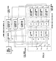
- Fig. 2 is a block diagram showing the arrangement of a first embodiment of this invention.
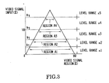
- Fig. 3 is a conceptual representation of the video signal level-range classification and video signal regions of the first embodiment.
- Fig. 4 shows the contents of a gain control data ROM of the first embodiment.
- Fig. 5 shows a relation obtained between a video signal and a region computing time of the first embodiment.
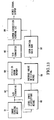
- Fig. 6 is a block diagram showing the arrangement of a second embodiment of the invention.
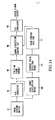
- Fig. 7 is a block diagram showing the arrangement of a third embodiment of the invention.
- Fig. 8 is a block diagram showing a fourth embodiment of the invention.
- Fig. 1 is a graph showing the conventional gamma correction characteristic.
- Fig. 2 is a block diagram showing the arrangement of a first embodiment of this invention.
- Fig. 3 is a conceptual representation of the video signal level-range classification and video signal regions of
- FIG. 9 is a conceptual representation of a relation obtained by the same embodiment between a video signal and its level ranges.
- Fig. 10 is a circuit diagram showing the level range classifying circuit of the same embodiment.
- Fig. 11 shows the contents of the gain control data ROM of the same embodiment.
- Fig. 12 shows a relation obtained by the same embodiment between a video signal and an average value detecting and ROM reading time.
- Fig. 13 is a block diagram showing a fifth embodiment of the invention.
- Fig. 14 is a block diagram showing a sixth embodiment.
- Fig. 2 shows in a block diagram a gamma correction device arranged according to this invention as a first embodiment thereof.
- the illustration includes an image sensing device 1.
- a gain control circuit 2 is arranged to vary the degree of gain according to voltage.
- Attenuation control circuits 3, 4 and 5 are arranged to vary, according to the voltage, the attenuation degree of signals of given level ranges.
- the power sources 6 to 9 produce voltages Vr1 to Vr4 as reference signal levels.
- the device further comprises comparison circuits 10 to 13; level trigger counters 14 to 17; and ROMs 18 to 21 for gain control data.
- a video signal supplied from the image sensing device 1 is compared by the comparison circuits 10 to 13 with the voltages Vr1 to Vr4 output from the reference power sources 6 to 9 as a plurality of reference signal levels.
- the concept of this comparison is as shown in Fig. 3.
- Each of the comparison circuits 10 to 13 produces a level signal at a high (H) level when the level of the input video signal exceeds the voltage.
- the input video signal is divided into different level ranges a1 to a5.
- the level trigger counters 14 to 17 respectively count the high level signals for the level ranges a1 to a4 in a level triggering manner.
- regions (integrating time values) A1 to A4 of these level ranges a1 to a4 are computed by the count numbers thus obtained.
- the gain control data ROMs 18 to 21 produce voltages for gain control according to the regions A1 to A4.
- the gain control circuit 2 and the attenuation control circuits 3 to 5 jointly form a gamma correction control circuit.
- Fig. 4 shows by way of example the contents of the gain control data ROMs.
- the gain control circuit 2 which controls the video signal gain of the overall level range is controlled by the output of the data ROM 18 as represented by G1-A1 data in Fig. 3.
- the attenuation degree (negative gain) of the video signal within the level range a2 is controlled by the attenuation control circuit 5 according to the output of the data ROM 19, as indicated by L1-A2 data in Fig. 4.
- the attenuation degree of the video signal within the level range a3 is controlled by the attenuation control circuit 4 according to the output of the data ROM 20, as indicated by L2-A3 data in Fig. 4. Further, the attenuation degree of the video signal within the level range a4 and above is controlled by the attenuation control circuit 3 according to the output of the data ROM 21, as indicated by L3-A4 data in Fig. 4. Through this process, the gamma correction characteristic is eventually controlled including a white compression correcting action on the video signal.
- the embodiment is arranged to allow the video signal of the level range a1 to pass through the attenuation control circuit 5 without attenuation.
- the arrangement of this embodiment can be advantageously applied to an electronic still video camera or the like that is arranged to be used for obtaining a still picture.
- a video signal to be used for computing the region is read out beforehand from the image sensing device 1 during a period of time between time points t1 and t2 as shown in Fig. 5.
- the region computing operation is performed during a period of time between time points t1 and t3.
- the gamma correction control is carried out over a video signal read out during a period between time points t4 and t5 according to the result of the region computing operation.
- Fig. 6 shows in a block diagram a second embodiment of the invention.
- the illustration includes an analog-to-digital (hereinafter referred to as A/D) converter 31; a field or frame memory 32; a digital-to-analog (hereinafter referred to as D/A) converter 33; and elements 34 to 37 which are arranged to perform the same functions as those of the corresponding elements shown in Fig. 2.
- A/D analog-to-digital
- D/A digital-to-analog
- a video signal read out from the image sensing device 1 is adequately gamma-corrected through a level range classifying means 35, a region computing means 36, a gain control data ROM 37 and a gamma correction control circuit 34 in the same manner as in the case of the first embodiment.
- the second embodiment differs from the first embodiment in that:
- the video signal is digitized by the A/D converter 31.
- the digital signal thus obtained is stored in the field or frame memory 32.
- the region is computed and apposite gamma correction data is read out from the gain control data ROM 37.
- the digital signal is converted back to an analog signal by the D/A converter 33. After that, the gamma correction is adequately carried out by the gamma correction control circuit 34.
- Fig. 7 shows in a block diagram the arrangement of a third embodiment of the invention.
- the video-signal-level-range classifying action is arranged to be performed on a digital signal obtained by digitizing the video signal by an A/D converter 31.
- a gamma correction control circuit 41, a level range classifying means 42, a region computing means 43 and a gain control data ROM 44 are arranged to perform their actions also on the digital signal in carrying out the gamma correction control.
- the process on the video signal in the form of a digital signal can be easily accomplished in accordance with the arrangement of a known digital signal processing circuit and, therefore, the details of the process are omitted from description.
- the gamma correction control is accomplished by the combined use of circuits which are arranged to control the gain or attenuation of the video signal according to the regions computed.
- this invention is not limited to that arrangement.
- the arrangement may be changed and the gamma correction control may be differently carried out, for example, in the following manner:
- Gamma correction characteristics which are categorically patternized to correspond to the above-stated regions are arranged beforehand and stored in a memory.
- An applicable categorical pattern is determined according to the value of each region of the input video signal. Then, the gamma correction control can be accomplished by reading out the applicable categorical pattern.
- each of the embodiments described is arranged to divide or classify the video signal obtained from the image sensing device into a plurality of signal level ranges; to compute the value of the region of the signal within each of the divided level ranges; and to control the gamma correction characteristic according to the values of the regions thus obtained.
- This arrangement enables the embodiment to make apposite gamma correction according to the brightness contrast of the image of the object. The arrangement thus effectively reduces the possibility of having white or black blank parts to give an image tone which is close to the luminosity factor of the human eye.
- Fig. 8 shows in a block diagram a gamma correction device which is arranged also according to this invention as a fourth embodiment thereof.
- the illustration includes an image sensing device 51; a gain control circuit 52 which is arranged to vary the degree of signal gain according to voltage; attenuation control circuits 53, 54 and 55 each of which is arranged to vary the degree of signal attenuation within a given level range; reference power sources 56, 57 and 58; and voltages Vr1, Vr2 and Vr3 which are produced from these power sources.
- a clipping circuit 60 is arranged to clip a video signal portion above the voltage Vr1.
- a slice circuit 61 is arranged to take out a video signal portion within a voltage range between the voltages Vr1 and Vr2.
- Another slice circuit 62 is arranged to take out a video signal portion within a voltage range between the voltages Vr2 and Vr3.
- Another clipping circuit 63 is arranged to clip a video signal portion below the voltage Vr3.
- the fourth embodiment further comprises low-pass filters (LPFs) 64 to 67; and gain control data ROMs 68 to 71.
- LPFs low-pass filters
- a video signal output from the image sensing device 51 is classified and divided by the clipping circuits 60 and 63 and the slice circuits 61 and 62 into different level ranges a1 to a4 according to the voltages Vr1, Vr2 and Vr3 output from the reference power sources 56, 57 and 58 as conceptually shown in Fig. 9.
- This clipping circuits 60 and 63 and the slice circuits 61 and 62 can be simply arranged as shown in Fig. 10. Referring to Fig. 10, the illustration includes resistors 75 to 78 and 86 to 90; diodes 79 to 84; PNP transistors 91, 92 and 93; and NPN transistors 94, 95 and 96.
- An input video signal which passes through the resistor 78 comes to the diode 84.
- a part of the video signal larger than the voltage Vr1 applied to the base of the transistor 96 is clipped off by the diode 84. Only a signal part within the level range a1 is allowed to be output from a terminal SA1.
- a signal passing through the resistor 77 has its part which is smaller than the voltage Vr1 applied to the base of the transistor 93 clipped off by the diode 82.
- Another signal part which is larger than the voltage Vr2 applied to the base of the transistor 95 is clipped off by the diode 83.
- a signal part which is between the voltages Vr1 and Vr2 is allowed to be output from a terminal SA2 in a sliced state.
- a terminal SA3 From a terminal SA3 is output a signal which is likewise obtained by slicing the input video signal part of a level between the voltages Vr2 and Vr3. Another signal obtained by slicing the input video signal part not exceeding the voltages Vr3 is output from a terminal SA4.
- the video signal is thus divided into the level ranges a1 to a4.
- the signals thus obtained are averaged through LPFs 64 to 67 to obtain the average values of the signals within the level ranges respectively.
- voltage signals which are to be used for gain control are read out from the gain control data ROMs 68 to 71 and are supplied to the above-stated circuits 52 to 55.
- the gain control circuit 52 and the attenuation control circuits 53, 54 and 55 form a gamma correction control circuit.
- Fig. 11 shows by way of example the contents of the gain control data ROMs 68 to 71.
- the gain of the video signals of all the level ranges shown in Fig. 9 is controlled by the gain control circuit 52 with the output of the data ROM 68 as indicated by G1-A1 data in Fig. 11.
- the attenuation degree (negative gain) of the video signal within the level range a2 is controlled by the attenuation control circuit 55 with the output of the data ROM 69 as indicated by L1-A2 data in Fig. 11.
- the attenuation degree of the video signal within the level range a3 is controlled by the attenuation control circuit 54 with the output of the data ROM 70 as indicated by L2-A3 in Fig. 11.
- the gain of the video signal within the level range a4 is controlled by the attenuation control circuit 53 with the output of the data ROM 71 as indicated by L3-A4 data in Fig. 11.
- the gamma correction characteristic is controlled including the white compressing correction of the video signal.
- the signal within the level range a1 is arranged to pass without attenuation through the attenuation control circuit 55.
- This embodiment requires time for detecting the average values of the video signal obtained within the level ranges and for reading out the gain control data on the basis of the results of detection. Therefore, the gamma correction cannot be accomplished in real time.
- the effect of this invention is advantageously attainable with the arrangement of this embodiment applied to an electronic still camera or the like.
- a one-field or -frame amount of the video signal is read out beforehand from the image sensing device 1 during a period between time points t1 and t2 as shown in Fig. 12.
- the average value of this amount of signal is detected during a period between time points t1 and t3.
- a degree of gamma correction control obtained as a result of this is applied to the video signal read out during a period between time points t4 and t5 as shown in Fig. 12.
- Fig. 13 shows in a block diagram a fifth embodiment of the invention.
- the illustration includes an A/D converter 101; a field or frame memory 102; a D/A converter 103; and other elements 104 to 107 which are arranged to function in the same manner as the blocks indicated by broken lines in Fig. 8.
- the fifth embodiment is arranged to make gamma correction on a video signal read out from an image sensing device 51 through a level range classifying means 105, an average value detecting means 106, a gain control data ROM 107 and a gamma correction control circuit 104 in the same manner as in the fourth embodiment.
- the video signal is digitized, at the same time, by the A/D converter 101 and the digitized signal is stored in the field or frame memory 102.
- the average value of the signal is detected by the average value detecting means 106; and apposite gamma correction data is read out from a gain control data ROM 107.
- the digital signal is converted back into an analog signal by the D/A converter 103 and then the gamma correction is appositely carried out through the gamma correction control circuit 104.
- Fig. 14 shows in a block diagram a sixth embodiment of the invention.
- This embodiment is arranged to perform the level range classifying action on a signal which has been digitized through an A/D converter 101.
- a gamma correction control circuit 108, a level range classifying means 109, an average value detecting means 110 and a gain control data ROM 111 are arranged to perform their actions on the digital signal before conversion back to an analog signal.
- the digital signal processing operation can be easily accomplished in accordance with the arrangement of a known digital signal processing circuit. Therefore, the details of it are omitted from description.
- the gamma correction control is performed by a combination of circuits which are arranged to control the signal gain or attenuation in accordance with the average value obtained for each of the level ranges.
- the arrangement may be changed as follows: Gamma correction characteristic data corresponding to the categorical patterns of the average values of the level ranges are stored in a memory; the categorical pattern of the average value of the input video signal is determined for each level range; and the gamma correction is controlled by reading out from the memory the gamma correction characteristic data which corresponds to the pattern. This method is advantageous in a case where gamma correction control is to be performed on a digital signal.
- the levels of the video signal obtained from the image sensing device are classified into a plurality of level ranges according to predetermined signal level values; the average or integrated value of the video signal obtained from within each of the level ranges is detected; and the gamma correction characteristic is controlled on the basis of the results of detection.
- This arrangement enables each of embodiments to make gamma correction appositely to the brightness contrast of the image sensing object.
- the invented arrangement gives an image with an adequate tone close to the luminosity factor of the human eye.
- a gamma correction device comprises a classifying circuit which divides an input video signal into a plurality of level ranges according to a plurality of signal levels; a computing circuit which computes the region of the video signal within each of the level ranges obtained by the classifying circuit; and a gamma correction control circuit which is arranged to have the gamma correction characteristic thereof controlled according to each region computed by the computing circuit, to gamma-correct the input video signal and to output the gamma-corrected video signal.
Abstract
Description
- This invention relates to a gamma correction device for an image sensing device or the like.
- Heretofore, to correct the non-linearity of the light emission characteristic of the luminescent material of a TV Braun tube, gamma correction has been made beforehand by an image sensing device, for example, on the basis of a gamma correction characteristic such as y = xγ and γ = 0.4 to 0.5 as shown in Fig. 1.
- However, in the above-stated example of the conventional arrangement, the gamma correction characteristic is always fixed. Therefore, in the event of a very bright object, for example, the image of the object cannot be fully reproduced on the Braun tube and the arrangement tends to give a blank white part.
- To solve this problem, there has been proposed a method of making white compressing correction as indicated with a broken line in Fig. 1. However, this method merely prevents bright image parts from becoming blank. According to this method, dark image parts or intermediate signal levels are apt to have an insufficient tone depending on the kind of the object. In cases where sunny and shady places commingle under sunlight within one and the same still picture in particular, both black and white (dark and bright) parts become blank to give a picture which is not adequately appreciable by the human eye.
- This invention is directed to the solution of the above-stated problems of the prior art. It is therefore an object of the invention to provide a gamma correction device which excels in tone reproducibility.
- To attain this object, a gamma correction device according to this invention is arranged to control a gamma correction characteristic according to the level regions of a video signal. More specifically, the device is arranged as described in the following paragraphs (1) and (2):
- (1) The device comprises the following elements a, b and c:
- a. Classifying means for classifying an input video signal with a plurality of signal levels into a plurality of level ranges.
- b. Computing means for computing a region of the video signal within each of the plurality of level ranges obtained by the classifying means.
- c. Gamma correction control means arranged to have a gamma correction characteristic controlled according to each region computed by the computing means, to gamma-correct the input video signal and to output the gamma-corrected video signal.
- (2) In the arrangement (1) above, the gamma correction control means is arranged such that gains of signals of the plurality of level ranges obtained by the classifying means are controlled separately from each other.
- In accordance with the arrangement described in Paragraphs (1) and (2) above, the gamma correction characteristic is controlled on the basis of the region of the input video signal for each of the level ranges.
- To attain the above-stated object, a gamma correction device which is another embodiment of this invention controls a gamma correction characteristic according to either an average value or an integrated value of the levels of a video signal obtained within each of different level ranges. More specifically, the device is arranged as described in the following paragraphs (3) and (4):
- (3) The device comprises the following elements:
- a. Classifying means for classifying an input video signal with a plurality of signal levels into a plurality of signal ranges.
- b. Detecting means for detecting an average or integrated value of the video signal for each of the plurality of level ranges obtained by the classifying means.
- c. Gamma correction control means arranged to have a gamma correction characteristic controlled according to the average or integrated value of the video signal detected by the detecting means for each of the plurality of level ranges, to gamma-correct the input video signal and to output the gamma-corrected video signal.
- (4) In the above-stated arrangement (3), the gamma correction control means is arranged such that gains of signals of the plurality of level ranges obtained by the classifying means are controlled separately from each other.
- In accordance with the arrangement described in Paragraphs (3) and (4), the gamma correction characteristic is controlled on the basis of the average or integrated value of the input video signal for each of the signal level ranges.
- The above and other objects and features of the invention will become apparent from the following detailed description of embodiments thereof taken in conjunction with the accompanying drawings.
- Fig. 1 is a graph showing the conventional gamma correction characteristic. Fig. 2 is a block diagram showing the arrangement of a first embodiment of this invention. Fig. 3 is a conceptual representation of the video signal level-range classification and video signal regions of the first embodiment. Fig. 4 shows the contents of a gain control data ROM of the first embodiment. Fig. 5 shows a relation obtained between a video signal and a region computing time of the first embodiment. Fig. 6 is a block diagram showing the arrangement of a second embodiment of the invention. Fig. 7 is a block diagram showing the arrangement of a third embodiment of the invention. Fig. 8 is a block diagram showing a fourth embodiment of the invention. Fig. 9 is a conceptual representation of a relation obtained by the same embodiment between a video signal and its level ranges. Fig. 10 is a circuit diagram showing the level range classifying circuit of the same embodiment. Fig. 11 shows the contents of the gain control data ROM of the same embodiment. Fig. 12 shows a relation obtained by the same embodiment between a video signal and an average value detecting and ROM reading time. Fig. 13 is a block diagram showing a fifth embodiment of the invention. Fig. 14 is a block diagram showing a sixth embodiment.
- Embodiments of the invention are described as follows:
- Fig. 2 shows in a block diagram a gamma correction device arranged according to this invention as a first embodiment thereof. Referring to Fig. 2, the illustration includes an
image sensing device 1. A gain control circuit 2 is arranged to vary the degree of gain according to voltage. Attenuation control circuits 3, 4 and 5 are arranged to vary, according to the voltage, the attenuation degree of signals of given level ranges. There are providedreference power sources 6 to 9. Thepower sources 6 to 9 produce voltages Vr1 to Vr4 as reference signal levels. The device further comprisescomparison circuits 10 to 13;level trigger counters 14 to 17; andROMs 18 to 21 for gain control data. - With the first embodiment arranged as described above, a video signal supplied from the
image sensing device 1 is compared by thecomparison circuits 10 to 13 with the voltages Vr1 to Vr4 output from thereference power sources 6 to 9 as a plurality of reference signal levels. The concept of this comparison is as shown in Fig. 3. Each of thecomparison circuits 10 to 13 produces a level signal at a high (H) level when the level of the input video signal exceeds the voltage. Through this process, the input video signal is divided into different level ranges a1 to a5. Thelevel trigger counters 14 to 17 respectively count the high level signals for the level ranges a1 to a4 in a level triggering manner. Then, regions (integrating time values) A1 to A4 of these level ranges a1 to a4 are computed by the count numbers thus obtained. The gaincontrol data ROMs 18 to 21 produce voltages for gain control according to the regions A1 to A4. - The gain control circuit 2 and the attenuation control circuits 3 to 5 jointly form a gamma correction control circuit. Fig. 4 shows by way of example the contents of the gain control data ROMs. The gain control circuit 2 which controls the video signal gain of the overall level range is controlled by the output of the
data ROM 18 as represented by G1-A1 data in Fig. 3. The attenuation degree (negative gain) of the video signal within the level range a2 is controlled by the attenuation control circuit 5 according to the output of the data ROM 19, as indicated by L1-A2 data in Fig. 4. The attenuation degree of the video signal within the level range a3 is controlled by the attenuation control circuit 4 according to the output of thedata ROM 20, as indicated by L2-A3 data in Fig. 4. Further, the attenuation degree of the video signal within the level range a4 and above is controlled by the attenuation control circuit 3 according to the output of thedata ROM 21, as indicated by L3-A4 data in Fig. 4. Through this process, the gamma correction characteristic is eventually controlled including a white compression correcting action on the video signal. - Further, the embodiment is arranged to allow the video signal of the level range a1 to pass through the attenuation control circuit 5 without attenuation.
- The above-stated arrangement necessitates the embodiment to have a period of time for computing the region according to the level range of the video signal. Therefore, the gamma correction cannot be carried out in real time. In view of this, the arrangement of this embodiment can be advantageously applied to an electronic still video camera or the like that is arranged to be used for obtaining a still picture. In that instance, a video signal to be used for computing the region is read out beforehand from the
image sensing device 1 during a period of time between time points t1 and t2 as shown in Fig. 5. After that, the region computing operation is performed during a period of time between time points t1 and t3. The gamma correction control is carried out over a video signal read out during a period between time points t4 and t5 according to the result of the region computing operation. - Fig. 6 shows in a block diagram a second embodiment of the invention. The illustration includes an analog-to-digital (hereinafter referred to as A/D)
converter 31; a field orframe memory 32; a digital-to-analog (hereinafter referred to as D/A)converter 33; andelements 34 to 37 which are arranged to perform the same functions as those of the corresponding elements shown in Fig. 2. - In the second embodiment, a video signal read out from the
image sensing device 1 is adequately gamma-corrected through a level range classifying means 35, a region computing means 36, a gaincontrol data ROM 37 and a gammacorrection control circuit 34 in the same manner as in the case of the first embodiment. The second embodiment, however, differs from the first embodiment in that: The video signal is digitized by the A/D converter 31. The digital signal thus obtained is stored in the field orframe memory 32. Meanwhile, the region is computed and apposite gamma correction data is read out from the gaincontrol data ROM 37. The digital signal is converted back to an analog signal by the D/A converter 33. After that, the gamma correction is adequately carried out by the gammacorrection control circuit 34. - Fig. 7 shows in a block diagram the arrangement of a third embodiment of the invention. In the case of the third embodiment, the video-signal-level-range classifying action is arranged to be performed on a digital signal obtained by digitizing the video signal by an A/
D converter 31. A gamma correction control circuit 41, a level range classifying means 42, a region computing means 43 and a gaincontrol data ROM 44 are arranged to perform their actions also on the digital signal in carrying out the gamma correction control. The process on the video signal in the form of a digital signal can be easily accomplished in accordance with the arrangement of a known digital signal processing circuit and, therefore, the details of the process are omitted from description. - In each of the embodiments described, the gamma correction control is accomplished by the combined use of circuits which are arranged to control the gain or attenuation of the video signal according to the regions computed. However, this invention is not limited to that arrangement. The arrangement may be changed and the gamma correction control may be differently carried out, for example, in the following manner: Gamma correction characteristics which are categorically patternized to correspond to the above-stated regions are arranged beforehand and stored in a memory. An applicable categorical pattern is determined according to the value of each region of the input video signal. Then, the gamma correction control can be accomplished by reading out the applicable categorical pattern.
- As described in the foregoing, each of the embodiments described is arranged to divide or classify the video signal obtained from the image sensing device into a plurality of signal level ranges; to compute the value of the region of the signal within each of the divided level ranges; and to control the gamma correction characteristic according to the values of the regions thus obtained. This arrangement enables the embodiment to make apposite gamma correction according to the brightness contrast of the image of the object. The arrangement thus effectively reduces the possibility of having white or black blank parts to give an image tone which is close to the luminosity factor of the human eye.
- Fig. 8 shows in a block diagram a gamma correction device which is arranged also according to this invention as a fourth embodiment thereof. The illustration includes an
image sensing device 51; again control circuit 52 which is arranged to vary the degree of signal gain according to voltage;attenuation control circuits reference power sources circuit 60 is arranged to clip a video signal portion above the voltage Vr1. Aslice circuit 61 is arranged to take out a video signal portion within a voltage range between the voltages Vr1 and Vr2. Anotherslice circuit 62 is arranged to take out a video signal portion within a voltage range between the voltages Vr2 and Vr3. Anotherclipping circuit 63 is arranged to clip a video signal portion below the voltage Vr3. - The fourth embodiment further comprises low-pass filters (LPFs) 64 to 67; and gain
control data ROMs 68 to 71. - In the arrangement described above, a video signal output from the
image sensing device 51 is classified and divided by the clippingcircuits slice circuits reference power sources circuits slice circuits resistors 75 to 78 and 86 to 90;diodes 79 to 84;PNP transistors NPN transistors resistor 78 comes to thediode 84. A part of the video signal larger than the voltage Vr1 applied to the base of thetransistor 96 is clipped off by thediode 84. Only a signal part within the level range a1 is allowed to be output from a terminal SA1. A signal passing through theresistor 77 has its part which is smaller than the voltage Vr1 applied to the base of thetransistor 93 clipped off by thediode 82. Another signal part which is larger than the voltage Vr2 applied to the base of thetransistor 95 is clipped off by thediode 83. As a result, a signal part which is between the voltages Vr1 and Vr2 is allowed to be output from a terminal SA2 in a sliced state. From a terminal SA3 is output a signal which is likewise obtained by slicing the input video signal part of a level between the voltages Vr2 and Vr3. Another signal obtained by slicing the input video signal part not exceeding the voltages Vr3 is output from a terminal SA4. - The video signal is thus divided into the level ranges a1 to a4. The signals thus obtained are averaged through
LPFs 64 to 67 to obtain the average values of the signals within the level ranges respectively. Then, in accordance with these average values of signals within the level ranges a1 to a4, voltage signals which are to be used for gain control are read out from the gaincontrol data ROMs 68 to 71 and are supplied to the above-statedcircuits 52 to 55. - The
gain control circuit 52 and theattenuation control circuits control data ROMs 68 to 71. The gain of the video signals of all the level ranges shown in Fig. 9 is controlled by thegain control circuit 52 with the output of thedata ROM 68 as indicated by G1-A1 data in Fig. 11. The attenuation degree (negative gain) of the video signal within the level range a2 is controlled by theattenuation control circuit 55 with the output of the data ROM 69 as indicated by L1-A2 data in Fig. 11. The attenuation degree of the video signal within the level range a3 is controlled by theattenuation control circuit 54 with the output of thedata ROM 70 as indicated by L2-A3 in Fig. 11. The gain of the video signal within the level range a4 is controlled by theattenuation control circuit 53 with the output of the data ROM 71 as indicated by L3-A4 data in Fig. 11. As a result, the gamma correction characteristic is controlled including the white compressing correction of the video signal. - Further, the signal within the level range a1 is arranged to pass without attenuation through the
attenuation control circuit 55. - This embodiment, as described in the foregoing, requires time for detecting the average values of the video signal obtained within the level ranges and for reading out the gain control data on the basis of the results of detection. Therefore, the gamma correction cannot be accomplished in real time. In view of this, the effect of this invention is advantageously attainable with the arrangement of this embodiment applied to an electronic still camera or the like. In that instance, for detecting the average value, a one-field or -frame amount of the video signal is read out beforehand from the
image sensing device 1 during a period between time points t1 and t2 as shown in Fig. 12. The average value of this amount of signal is detected during a period between time points t1 and t3. Then, a degree of gamma correction control obtained as a result of this is applied to the video signal read out during a period between time points t4 and t5 as shown in Fig. 12. - The same operation can be accomplished with the
LPFs 64 to 67 replaced with integrating circuits. - Fig. 13 shows in a block diagram a fifth embodiment of the invention. The illustration includes an A/
D converter 101; a field orframe memory 102; a D/A converter 103; andother elements 104 to 107 which are arranged to function in the same manner as the blocks indicated by broken lines in Fig. 8. - The fifth embodiment is arranged to make gamma correction on a video signal read out from an
image sensing device 51 through a level range classifying means 105, an average value detecting means 106, a gaincontrol data ROM 107 and a gammacorrection control circuit 104 in the same manner as in the fourth embodiment. However, in the case of the fifth embodiment, the video signal is digitized, at the same time, by the A/D converter 101 and the digitized signal is stored in the field orframe memory 102. Meanwhile, the average value of the signal is detected by the average value detecting means 106; and apposite gamma correction data is read out from a gaincontrol data ROM 107. After that, the digital signal is converted back into an analog signal by the D/A converter 103 and then the gamma correction is appositely carried out through the gammacorrection control circuit 104. - Fig. 14 shows in a block diagram a sixth embodiment of the invention. This embodiment is arranged to perform the level range classifying action on a signal which has been digitized through an A/
D converter 101. A gammacorrection control circuit 108, a level range classifying means 109, an average value detecting means 110 and a gaincontrol data ROM 111 are arranged to perform their actions on the digital signal before conversion back to an analog signal. The digital signal processing operation can be easily accomplished in accordance with the arrangement of a known digital signal processing circuit. Therefore, the details of it are omitted from description. - In each of the embodiments described, the gamma correction control is performed by a combination of circuits which are arranged to control the signal gain or attenuation in accordance with the average value obtained for each of the level ranges. However, the invention is not limited to this arrangement. For example, the arrangement may be changed as follows: Gamma correction characteristic data corresponding to the categorical patterns of the average values of the level ranges are stored in a memory; the categorical pattern of the average value of the input video signal is determined for each level range; and the gamma correction is controlled by reading out from the memory the gamma correction characteristic data which corresponds to the pattern. This method is advantageous in a case where gamma correction control is to be performed on a digital signal.
- In accordance with the invented arrangement which has been described in the foregoing, the levels of the video signal obtained from the image sensing device are classified into a plurality of level ranges according to predetermined signal level values; the average or integrated value of the video signal obtained from within each of the level ranges is detected; and the gamma correction characteristic is controlled on the basis of the results of detection. This arrangement enables each of embodiments to make gamma correction appositely to the brightness contrast of the image sensing object. Therefore, the invented arrangement gives an image with an adequate tone close to the luminosity factor of the human eye.
- A gamma correction device comprises a classifying circuit which divides an input video signal into a plurality of level ranges according to a plurality of signal levels; a computing circuit which computes the region of the video signal within each of the level ranges obtained by the classifying circuit; and a gamma correction control circuit which is arranged to have the gamma correction characteristic thereof controlled according to each region computed by the computing circuit, to gamma-correct the input video signal and to output the gamma-corrected video signal.
Claims (30)
said characteristic is varied for every one of different level ranges; and
the level of said video signal is controlled for every one of said level ranges on the basis of said varied characteristics to output the level-controlled video signal.
Applications Claiming Priority (4)
| Application Number | Priority Date | Filing Date | Title |
|---|---|---|---|
| JP1025819A JP2696378B2 (en) | 1989-02-06 | 1989-02-06 | Non-linear processing unit |
| JP25820/89 | 1989-02-06 | ||
| JP25819/89 | 1989-02-06 | ||
| JP1025820A JPH02206283A (en) | 1989-02-06 | 1989-02-06 | Gamma correcting device |
Publications (2)
| Publication Number | Publication Date |
|---|---|
| EP0382100A1 true EP0382100A1 (en) | 1990-08-16 |
| EP0382100B1 EP0382100B1 (en) | 1995-05-17 |
Family
ID=26363513
Family Applications (1)
| Application Number | Title | Priority Date | Filing Date |
|---|---|---|---|
| EP90102028A Expired - Lifetime EP0382100B1 (en) | 1989-02-06 | 1990-02-01 | Gamma correction device |
Country Status (4)
| Country | Link |
|---|---|
| US (1) | US5089890A (en) |
| EP (1) | EP0382100B1 (en) |
| CA (1) | CA2008690C (en) |
| DE (1) | DE69019391T2 (en) |
Cited By (7)
| Publication number | Priority date | Publication date | Assignee | Title |
|---|---|---|---|---|
| GB2250886A (en) * | 1990-12-13 | 1992-06-17 | Rank Cintel Ltd | Noise reduction in video signals |
| US5243426A (en) * | 1990-05-14 | 1993-09-07 | Sony Corporation | Circuit for gamma correction of a digital video signal and having a memory for storing data defining a desired gamma correction characteristic |
| EP0648043A1 (en) * | 1993-10-08 | 1995-04-12 | Koninklijke Philips Electronics N.V. | Picture signal enhancement circuit |
| EP0654942A1 (en) * | 1993-11-23 | 1995-05-24 | Koninklijke Philips Electronics N.V. | Non-linear signal processing |
| WO1997028644A1 (en) * | 1996-12-10 | 1997-08-07 | Yalestown Corporation N.V. | Method of forming, monitoring and receiving a television signal |
| KR100386080B1 (en) * | 1996-09-16 | 2003-08-21 | 주식회사 하이닉스반도체 | Apparatus for compensating gamma of video signals |
| US7050114B2 (en) | 2001-04-11 | 2006-05-23 | Koninklijke Philips Electronics N.V. | Picture signal contrast control |
Families Citing this family (22)
| Publication number | Priority date | Publication date | Assignee | Title |
|---|---|---|---|---|
| US5257108A (en) * | 1990-08-06 | 1993-10-26 | Koji Muraoka | Video signal processing circuit for improving contrast for an LCD display |
| US5196924A (en) * | 1991-07-22 | 1993-03-23 | International Business Machines, Corporation | Look-up table based gamma and inverse gamma correction for high-resolution frame buffers |
| DE4137373C1 (en) * | 1991-11-13 | 1993-06-17 | Siemens Ag, 8000 Muenchen, De | |
| KR950005050Y1 (en) * | 1991-12-05 | 1995-06-21 | 삼성전자 주식회사 | Analog circuit for disital camera |
| JPH05191675A (en) * | 1992-01-14 | 1993-07-30 | Canon Inc | Gamma correction circuit and image pickup device using the circuit |
| JP3386495B2 (en) * | 1992-09-14 | 2003-03-17 | 富士写真フイルム株式会社 | Digital electronic still camera and control method thereof |
| JP3074967B2 (en) * | 1992-10-27 | 2000-08-07 | 松下電器産業株式会社 | High dynamic range imaging / synthesis method and high dynamic range imaging apparatus |
| JP3302423B2 (en) * | 1992-12-28 | 2002-07-15 | キヤノン株式会社 | Imaging device |
| KR0149737B1 (en) * | 1993-07-20 | 1998-10-15 | 사토 후미오 | Solid state imaging apparatus |
| KR0142263B1 (en) * | 1994-08-06 | 1998-06-15 | 김광호 | Digital gamma correction method and apparatus thereof |
| KR960028705A (en) * | 1994-12-08 | 1996-07-22 | 이헌조 | Color electroluminescent (EL) device and its manufacturing method |
| KR960024524A (en) * | 1994-12-21 | 1996-07-20 | 김광호 | Gamma Correction Device of Liquid Crystal Display Using Memory Device |
| JP3316351B2 (en) * | 1995-09-27 | 2002-08-19 | シャープ株式会社 | AGC device |
| KR0185136B1 (en) * | 1996-02-21 | 1999-04-15 | 김광호 | Apparatus for increasing image clearness of vcr |
| KR100206792B1 (en) * | 1996-07-16 | 1999-07-01 | 구자홍 | Device for improving tv picture quality by using gamma compensation |
| US6215529B1 (en) * | 1997-03-06 | 2001-04-10 | Matsushita Electric Industrial Co. Ltd. | Gamma compensation apparatus |
| JPH11143379A (en) * | 1997-09-03 | 1999-05-28 | Semiconductor Energy Lab Co Ltd | Semiconductor display device correcting system and its method |
| US6633343B2 (en) * | 2000-03-14 | 2003-10-14 | Matsushita Electric Industrial Co., Ltd. | Dynamic gamma correction apparatus |
| US7038721B2 (en) | 2002-02-15 | 2006-05-02 | Koninklijke Philips Electronics N.V. | Gamma correction circuit |
| JP4271978B2 (en) * | 2003-04-18 | 2009-06-03 | 株式会社日立製作所 | Video display device |
| JP4311166B2 (en) * | 2003-11-05 | 2009-08-12 | ソニー株式会社 | Information signal processing apparatus and processing method, coefficient seed data generating apparatus and generating method used therefor, program for executing each method, and medium recording the program |
| US20180096641A1 (en) * | 2016-09-30 | 2018-04-05 | Himax Display, Inc. | Gamma improvement method and associated electronic device |
Citations (3)
| Publication number | Priority date | Publication date | Assignee | Title |
|---|---|---|---|---|
| US3277318A (en) * | 1964-04-30 | 1966-10-04 | Gen Electric | Gamma correction circuits |
| US4394688A (en) * | 1981-08-25 | 1983-07-19 | Hamamatsu Systems, Inc. | Video system having an adjustable digital gamma correction for contrast enhancement |
| GB2113945A (en) * | 1981-10-13 | 1983-08-10 | Dainippon Screen Mfg | Picture digital processing |
Family Cites Families (4)
| Publication number | Priority date | Publication date | Assignee | Title |
|---|---|---|---|---|
| JPS5230319A (en) * | 1975-09-04 | 1977-03-08 | Nippon Hoso Kyokai <Nhk> | Compensation circuit of digital type gamma |
| DE3107901A1 (en) * | 1981-03-02 | 1982-09-16 | Siemens AG, 1000 Berlin und 8000 München | DIGITAL REAL-TIME TELEVISION IMAGE DEVICE |
| JPS60139080A (en) * | 1983-12-27 | 1985-07-23 | Canon Inc | Picture forming device |
| GB8521019D0 (en) * | 1985-08-22 | 1986-10-01 | Rank Pullin Controls Ltd | Imaging apparatus |
-
1990
- 1990-01-24 US US07/469,144 patent/US5089890A/en not_active Expired - Lifetime
- 1990-01-26 CA CA002008690A patent/CA2008690C/en not_active Expired - Lifetime
- 1990-02-01 DE DE69019391T patent/DE69019391T2/en not_active Expired - Fee Related
- 1990-02-01 EP EP90102028A patent/EP0382100B1/en not_active Expired - Lifetime
Patent Citations (3)
| Publication number | Priority date | Publication date | Assignee | Title |
|---|---|---|---|---|
| US3277318A (en) * | 1964-04-30 | 1966-10-04 | Gen Electric | Gamma correction circuits |
| US4394688A (en) * | 1981-08-25 | 1983-07-19 | Hamamatsu Systems, Inc. | Video system having an adjustable digital gamma correction for contrast enhancement |
| GB2113945A (en) * | 1981-10-13 | 1983-08-10 | Dainippon Screen Mfg | Picture digital processing |
Cited By (11)
| Publication number | Priority date | Publication date | Assignee | Title |
|---|---|---|---|---|
| US5243426A (en) * | 1990-05-14 | 1993-09-07 | Sony Corporation | Circuit for gamma correction of a digital video signal and having a memory for storing data defining a desired gamma correction characteristic |
| GB2250886A (en) * | 1990-12-13 | 1992-06-17 | Rank Cintel Ltd | Noise reduction in video signals |
| GB2250886B (en) * | 1990-12-13 | 1995-06-14 | Rank Cintel Ltd | Noise reduction in video signals |
| US5557340A (en) * | 1990-12-13 | 1996-09-17 | Rank Cintel Limited | Noise reduction in video signals |
| EP0648043A1 (en) * | 1993-10-08 | 1995-04-12 | Koninklijke Philips Electronics N.V. | Picture signal enhancement circuit |
| BE1007608A3 (en) * | 1993-10-08 | 1995-08-22 | Philips Electronics Nv | Improving picture signal circuit. |
| EP0654942A1 (en) * | 1993-11-23 | 1995-05-24 | Koninklijke Philips Electronics N.V. | Non-linear signal processing |
| BE1007777A3 (en) * | 1993-11-23 | 1995-10-17 | Philips Electronics Nv | Non-linear signal. |
| KR100386080B1 (en) * | 1996-09-16 | 2003-08-21 | 주식회사 하이닉스반도체 | Apparatus for compensating gamma of video signals |
| WO1997028644A1 (en) * | 1996-12-10 | 1997-08-07 | Yalestown Corporation N.V. | Method of forming, monitoring and receiving a television signal |
| US7050114B2 (en) | 2001-04-11 | 2006-05-23 | Koninklijke Philips Electronics N.V. | Picture signal contrast control |
Also Published As
| Publication number | Publication date |
|---|---|
| US5089890A (en) | 1992-02-18 |
| CA2008690A1 (en) | 1990-08-06 |
| CA2008690C (en) | 1994-12-27 |
| DE69019391D1 (en) | 1995-06-22 |
| EP0382100B1 (en) | 1995-05-17 |
| DE69019391T2 (en) | 1995-10-26 |
Similar Documents
| Publication | Publication Date | Title |
|---|---|---|
| US5089890A (en) | Gamma correction device | |
| CN1025274C (en) | Gradation corrector | |
| KR100512542B1 (en) | Image quality correction circuit for video signals | |
| US20050190272A1 (en) | Image signal processor | |
| KR960001027B1 (en) | Contrast correction device | |
| US5070405A (en) | Electronic still camera with multi-area light metering and gray scale modification | |
| EP0271912B1 (en) | Method of reducing noise in a multi-gradation image signal | |
| US5283635A (en) | White balance adjusting device with plural thresholds for range control | |
| JP2696378B2 (en) | Non-linear processing unit | |
| US5940144A (en) | Device for regulating the contrast of video images | |
| US5650784A (en) | Digital AGC circuit for image processing | |
| US20040196394A1 (en) | Gamma correction device in image capturing apparatus | |
| JP3788997B2 (en) | Image signal processing device | |
| US5959694A (en) | Video signal with contour adjustment processing apparatus | |
| US7233705B2 (en) | Method and apparatus for reducing inaccuracies when processing color data with a tone map | |
| JPH04340875A (en) | Image pickup device | |
| JP2869976B2 (en) | Imaging device | |
| JP2586851B2 (en) | liquid crystal television | |
| JPS63157556A (en) | Picture reading device | |
| JP3618849B2 (en) | A / D converter for fundus image | |
| JPH04258087A (en) | Video signal processing circuit | |
| JPH07240839A (en) | Image processor | |
| JPS6046173A (en) | A/d converting circuit of picture signal | |
| JP2752527B2 (en) | Halftone processing circuit | |
| KR0174090B1 (en) | Auto-knee circuit & gamma correcting circuit for video camera |
Legal Events
| Date | Code | Title | Description |
|---|---|---|---|
| PUAI | Public reference made under article 153(3) epc to a published international application that has entered the european phase |
Free format text: ORIGINAL CODE: 0009012 |
|
| AK | Designated contracting states |
Kind code of ref document: A1 Designated state(s): DE FR GB NL |
|
| 17P | Request for examination filed |
Effective date: 19901221 |
|
| 17Q | First examination report despatched |
Effective date: 19930308 |
|
| GRAA | (expected) grant |
Free format text: ORIGINAL CODE: 0009210 |
|
| AK | Designated contracting states |
Kind code of ref document: B1 Designated state(s): DE FR GB NL |
|
| REF | Corresponds to: |
Ref document number: 69019391 Country of ref document: DE Date of ref document: 19950622 |
|
| ET | Fr: translation filed | ||
| PLBE | No opposition filed within time limit |
Free format text: ORIGINAL CODE: 0009261 |
|
| STAA | Information on the status of an ep patent application or granted ep patent |
Free format text: STATUS: NO OPPOSITION FILED WITHIN TIME LIMIT |
|
| 26N | No opposition filed | ||
| REG | Reference to a national code |
Ref country code: GB Ref legal event code: IF02 |
|
| PGFP | Annual fee paid to national office [announced via postgrant information from national office to epo] |
Ref country code: NL Payment date: 20080220 Year of fee payment: 19 Ref country code: DE Payment date: 20080229 Year of fee payment: 19 Ref country code: GB Payment date: 20080226 Year of fee payment: 19 |
|
| PGFP | Annual fee paid to national office [announced via postgrant information from national office to epo] |
Ref country code: FR Payment date: 20080221 Year of fee payment: 19 |
|
| GBPC | Gb: european patent ceased through non-payment of renewal fee |
Effective date: 20090201 |
|
| NLV4 | Nl: lapsed or anulled due to non-payment of the annual fee |
Effective date: 20090901 |
|
| REG | Reference to a national code |
Ref country code: FR Ref legal event code: ST Effective date: 20091030 |
|
| PG25 | Lapsed in a contracting state [announced via postgrant information from national office to epo] |
Ref country code: NL Free format text: LAPSE BECAUSE OF NON-PAYMENT OF DUE FEES Effective date: 20090901 |
|
| PG25 | Lapsed in a contracting state [announced via postgrant information from national office to epo] |
Ref country code: DE Free format text: LAPSE BECAUSE OF NON-PAYMENT OF DUE FEES Effective date: 20090901 |
|
| PG25 | Lapsed in a contracting state [announced via postgrant information from national office to epo] |
Ref country code: GB Free format text: LAPSE BECAUSE OF NON-PAYMENT OF DUE FEES Effective date: 20090201 Ref country code: FR Free format text: LAPSE BECAUSE OF NON-PAYMENT OF DUE FEES Effective date: 20090302 |