EP0382484A2 - Hermaphroditic coupling for anatomical thermal system - Google Patents
Hermaphroditic coupling for anatomical thermal system Download PDFInfo
- Publication number
- EP0382484A2 EP0382484A2 EP90301246A EP90301246A EP0382484A2 EP 0382484 A2 EP0382484 A2 EP 0382484A2 EP 90301246 A EP90301246 A EP 90301246A EP 90301246 A EP90301246 A EP 90301246A EP 0382484 A2 EP0382484 A2 EP 0382484A2
- Authority
- EP
- European Patent Office
- Prior art keywords
- end wall
- extending
- element according
- lumen
- arm
- Prior art date
- Legal status (The legal status is an assumption and is not a legal conclusion. Google has not performed a legal analysis and makes no representation as to the accuracy of the status listed.)
- Granted
Links
Images

Classifications
-
- A—HUMAN NECESSITIES
- A61—MEDICAL OR VETERINARY SCIENCE; HYGIENE
- A61F—FILTERS IMPLANTABLE INTO BLOOD VESSELS; PROSTHESES; DEVICES PROVIDING PATENCY TO, OR PREVENTING COLLAPSING OF, TUBULAR STRUCTURES OF THE BODY, e.g. STENTS; ORTHOPAEDIC, NURSING OR CONTRACEPTIVE DEVICES; FOMENTATION; TREATMENT OR PROTECTION OF EYES OR EARS; BANDAGES, DRESSINGS OR ABSORBENT PADS; FIRST-AID KITS
- A61F7/00—Heating or cooling appliances for medical or therapeutic treatment of the human body
- A61F7/02—Compresses or poultices for effecting heating or cooling
-
- F—MECHANICAL ENGINEERING; LIGHTING; HEATING; WEAPONS; BLASTING
- F16—ENGINEERING ELEMENTS AND UNITS; GENERAL MEASURES FOR PRODUCING AND MAINTAINING EFFECTIVE FUNCTIONING OF MACHINES OR INSTALLATIONS; THERMAL INSULATION IN GENERAL
- F16L—PIPES; JOINTS OR FITTINGS FOR PIPES; SUPPORTS FOR PIPES, CABLES OR PROTECTIVE TUBING; MEANS FOR THERMAL INSULATION IN GENERAL
- F16L37/00—Couplings of the quick-acting type
- F16L37/08—Couplings of the quick-acting type in which the connection between abutting or axially overlapping ends is maintained by locking members
- F16L37/084—Couplings of the quick-acting type in which the connection between abutting or axially overlapping ends is maintained by locking members combined with automatic locking
- F16L37/098—Couplings of the quick-acting type in which the connection between abutting or axially overlapping ends is maintained by locking members combined with automatic locking by means of flexible hooks
-
- F—MECHANICAL ENGINEERING; LIGHTING; HEATING; WEAPONS; BLASTING
- F16—ENGINEERING ELEMENTS AND UNITS; GENERAL MEASURES FOR PRODUCING AND MAINTAINING EFFECTIVE FUNCTIONING OF MACHINES OR INSTALLATIONS; THERMAL INSULATION IN GENERAL
- F16L—PIPES; JOINTS OR FITTINGS FOR PIPES; SUPPORTS FOR PIPES, CABLES OR PROTECTIVE TUBING; MEANS FOR THERMAL INSULATION IN GENERAL
- F16L37/00—Couplings of the quick-acting type
- F16L37/28—Couplings of the quick-acting type with fluid cut-off means
- F16L37/30—Couplings of the quick-acting type with fluid cut-off means with fluid cut-off means in each of two pipe-end fittings
- F16L37/32—Couplings of the quick-acting type with fluid cut-off means with fluid cut-off means in each of two pipe-end fittings at least one of two lift valves being opened automatically when the coupling is applied
-
- F—MECHANICAL ENGINEERING; LIGHTING; HEATING; WEAPONS; BLASTING
- F16—ENGINEERING ELEMENTS AND UNITS; GENERAL MEASURES FOR PRODUCING AND MAINTAINING EFFECTIVE FUNCTIONING OF MACHINES OR INSTALLATIONS; THERMAL INSULATION IN GENERAL
- F16L—PIPES; JOINTS OR FITTINGS FOR PIPES; SUPPORTS FOR PIPES, CABLES OR PROTECTIVE TUBING; MEANS FOR THERMAL INSULATION IN GENERAL
- F16L37/00—Couplings of the quick-acting type
- F16L37/56—Couplings of the quick-acting type for double-walled or multi-channel pipes or pipe assemblies
-
- A—HUMAN NECESSITIES
- A61—MEDICAL OR VETERINARY SCIENCE; HYGIENE
- A61F—FILTERS IMPLANTABLE INTO BLOOD VESSELS; PROSTHESES; DEVICES PROVIDING PATENCY TO, OR PREVENTING COLLAPSING OF, TUBULAR STRUCTURES OF THE BODY, e.g. STENTS; ORTHOPAEDIC, NURSING OR CONTRACEPTIVE DEVICES; FOMENTATION; TREATMENT OR PROTECTION OF EYES OR EARS; BANDAGES, DRESSINGS OR ABSORBENT PADS; FIRST-AID KITS
- A61F7/00—Heating or cooling appliances for medical or therapeutic treatment of the human body
- A61F2007/0054—Heating or cooling appliances for medical or therapeutic treatment of the human body with a closed fluid circuit, e.g. hot water
-
- Y—GENERAL TAGGING OF NEW TECHNOLOGICAL DEVELOPMENTS; GENERAL TAGGING OF CROSS-SECTIONAL TECHNOLOGIES SPANNING OVER SEVERAL SECTIONS OF THE IPC; TECHNICAL SUBJECTS COVERED BY FORMER USPC CROSS-REFERENCE ART COLLECTIONS [XRACs] AND DIGESTS
- Y10—TECHNICAL SUBJECTS COVERED BY FORMER USPC
- Y10T—TECHNICAL SUBJECTS COVERED BY FORMER US CLASSIFICATION
- Y10T137/00—Fluid handling
- Y10T137/8593—Systems
- Y10T137/87917—Flow path with serial valves and/or closures
- Y10T137/87925—Separable flow path section, valve or closure in each
- Y10T137/87941—Each valve and/or closure operated by coupling motion
- Y10T137/87949—Linear motion of flow path sections operates both
- Y10T137/87957—Valves actuate each other
Definitions
- This invention relates to a hermaphroditic coupling or connector useful in an anatomical thermal system and, more particularly, to the type of system employing two tubes for the conduction of the thermal fluid, i.e., for heating or cooling.
- the present invention makes use of a pair of connecting elements having hermaphroditic ends, i.e., both male and female which results in error-proof connection and operation.
- the invention provides a novel squeezable latching means for releasably connecting together the two hermaphroditic elements.
- the numeral 10 designates generally pad means of the nature used in thermal treatment of patients by application to the body and which is usually equipped with interior conduit means shown schematically as at 11.
- Supply tubing or conduit means for the thermal fluid (hot/cold) is provided at 12 and the return line at 13.
- These lines are coupled to a control unit 14 by means of a hermaphroditic connector or coupling 15.
- the coupling 15 includes elements 15a and 15b which, in the illustration given are identical.
- the connected ends, i.e., the hermaphroditic ends be identical because where the element 15b is mounted on or in the control unit 14, the end opposite to the hermaphroditic end may be varied somewhat.
- each of the elements 15a and 15b consist of a block-like body 16.
- the body 16 has a top wall 17 and a bottom or lower wall 18 - see Fig. 8. In the illustration given, these walls are substantially planar and are flanked by sidewalls 19 and 20 - see also Fig. 4.
- each body 16 is defined by end walls 21,22, one end wall 21 remote from the hermaphroditic coupling and one end wall 22 carrying the hermaphroditic elements and referred to as hermaphroditic end wall; see particularly the element 15b at the right hand portion of Fig. 3.
- Each body 16 has a pair of longitudinally extending lumens therein, namely a first lumen 23 and a second lumen 24 at the left hand portion of Fig. 4.
- the first and second lumens 23,24 can be considered to be essentially longitudinally extending and further extend from one end wall 21 of the body 16 to the other end wall 22 so as to provide a through passage for the thermal fluid.
- Each lumen 23,24 in each element 15a,15b is equipped with a check valve as at 25 in the upper left hand portion of Fig.4.
- Check valves in the nature of poppets are conventional in thermal treatment systems and, therefore, a wide variety of specific designs are available for the person skilled in the art practising the instant invention.
- Fig. 5 where the numeral 26 designates generally the basic component of the body 16.
- the showing in Fig. 5 is essentially that of the element 15a, i.e. with the hermaphroditic end wall 22 being to the right.
- the hermaphroditic end wall 22 is seen to be stepped as at 27 - compare Fig. 5 with the central portions of Fig. 3. This divides the end wall 22 into a first portion 28 which is positioned closer to the end wall 21 than the second portion 29 - for convenience compare the right hand portion of Fig. 3.
- the step 27 is seen to be positioned along the longitudinal midplane of the body 16 or 26 and thus lies between the axis of the first lumen 23 and the axis of the second lumen 24.
- a male projection 30 Extending longitudinally away from the first portion 28 is a male projection 30 which is aligned with the first lumen 23. Extending inwardly, i.e. toward the end wall 21 from the end wall 22, is a recess 31 in the second portion 29. The interior contour of the recess 31 conforms to the external contour of the projection 30 and, in effect, is also a continuation of the second lumen 24.
- FIG. 6 it will be seen at the extreme left hand portion thereof that there is a pair of coupling elements 32 and 33 which couple the first and second lumens 23,24 to the tubes 13,12, respectively.
- the adapter 34 shown in Fig. 6 is associated with the first lumen 23 and includes a first portion 35 which is relatively tapered so as to fit within the relatively tapered bore 36 of the body 26 - see Fig. 5.
- the body is also equipped with a second tapered bore 37 which receives a first tapered portion 38 of the adaptor 39 shown in Fig. 7 and associated with the second lumen 24.
- the tapered portion 38 is shorter than the tapered portion 35 due to the difference in length of the bores 36,37.
- the adaptors 34,39 are identical in providing second portions 40,41 for the ensleeving receipt of the tubes 13,12, respectively. It is advantageous to provide the tapered portions in the form of split fingers 42 as illustrated also in Fig. 9 so as to facilitate assembly.
- squeezable latching means coupling the elements 15a,15b. These again are essentially male and female as can be appreciated from a consideration of Figs. 3 and 4.
- the numeral 43 designates an arm which extends longitudinally away from the first portion 28 of the hermaphroditic end wall 22 - and on the side of the projection 30 remote from the second lumen 24. It will be noted that the fee end 44 of the arm 43 is equipped with a barbed portion 45 which passes through a passage 46 - see Fig. 3 at the right hand end thereof - for snap engagement against an intermediate wall 47 (compare Figs. 4 and 5). It will be appreciated that an identical arrangement is provided on the element 15b as can be appreciated from the arm 48 in the upper right hand portion of Fig. 3.
- a cam release feature which includes a a second arm 49 also extending longitudinally but not quite as far as the arm 42.
- the arm 49 - see the upper central portion of Fig. 5 is equipped with a camming surface 50 which bears against the barb 44 - see Fig. 4.
- the bodies 16 are constructed of resilient plastic material which, because of the relatively thin section of the arms 43,49, can be flexed so as to perform the squeezing action just referred to. It is also advantageous to groove the exterior of the arms as at 51 and 52 - see Fig. 2.
Abstract
Description
- This invention relates to a hermaphroditic coupling or connector useful in an anatomical thermal system and, more particularly, to the type of system employing two tubes for the conduction of the thermal fluid, i.e., for heating or cooling.
- There has been widespread use of thermal pads for placement on the body of a patient so as to either heat or cool the area contacted. The pad is connected by a supply and return tubing to a control mechanism which usually includes a pump or other prime mover. In the past, there have been instances of misconnection whereby the return line was connected to the supply side and vice versa resulting in the need for readjustment. This significant drawback is avoided by the teachings of the present invention.
- The present invention makes use of a pair of connecting elements having hermaphroditic ends, i.e., both male and female which results in error-proof connection and operation.
- Additionally, the invention provides a novel squeezable latching means for releasably connecting together the two hermaphroditic elements.
- Other objects and advantages of the invention may be seen in the details of the ensuing specification.
- The invention is explained by way of example, in conjunction with an illustrative embodiment in the accompanying diagrammatic drawing, in which:
- Fig. 1 is a schematic view of a typical hospital installation featuring the use of the invention;
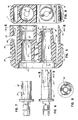
- Fig. 2 is an enlarged fragmentary perspective view of the coupled hermaphroditic elements of the invention;
- Fig. 3 is a view similar to Fig. 2 but with the hermaphroditic elements separated so as to more clearly delineate the structural features of the hermaphroditic ends of the two elements;
- Fig. 4 is a longitudinal sectional view of the coupled elements;
- Fig. 5 is a sectional view of the generally block-like body of each element;
- Figs. 6 and 7 are side elevational views of adaptors introduced into the body of Fig. 5 so as to provide the connections to tubing away from the hermaphroditic end thereof;
- Fig. 8 is a sectional view seen along the sight line 8-8 applied to Fig. 5; and
- Fig. 9 is a sectional view taken along the sight line 9-9 applied to Fig. 6.
- Referring to Fig. 1, the numeral 10 designates generally pad means of the nature used in thermal treatment of patients by application to the body and which is usually equipped with interior conduit means shown schematically as at 11. Supply tubing or conduit means for the thermal fluid (hot/cold) is provided at 12 and the return line at 13. These lines are coupled to a
control unit 14 by means of a hermaphroditic connector orcoupling 15. More particularly, thecoupling 15 includeselements 15a and 15b which, in the illustration given are identical. The important aspect is that the connected ends, i.e., the hermaphroditic ends, be identical because where theelement 15b is mounted on or in thecontrol unit 14, the end opposite to the hermaphroditic end may be varied somewhat. However, for ease of presentation and understanding, the invention will be described in connection withelements 15a and 15b that are identical. These can be seen in larger scale in Fig. 2 and in greater detail insofar as the hermaphroditic ends are concerned, in Fig. 3. - Referring now to Fig. 3, each of the
elements 15a and 15b consist of a block-like body 16. Thebody 16 has atop wall 17 and a bottom or lower wall 18 - see Fig. 8. In the illustration given, these walls are substantially planar and are flanked bysidewalls 19 and 20 - see also Fig. 4. Finally, eachbody 16 is defined byend walls end wall 21 remote from the hermaphroditic coupling and oneend wall 22 carrying the hermaphroditic elements and referred to as hermaphroditic end wall; see particularly theelement 15b at the right hand portion of Fig. 3. - Each
body 16 has a pair of longitudinally extending lumens therein, namely afirst lumen 23 and asecond lumen 24 at the left hand portion of Fig. 4. The first andsecond lumens end wall 21 of thebody 16 to theother end wall 22 so as to provide a through passage for the thermal fluid. Eachlumen element 15a,15b is equipped with a check valve as at 25 in the upper left hand portion of Fig.4. Check valves in the nature of poppets are conventional in thermal treatment systems and, therefore, a wide variety of specific designs are available for the person skilled in the art practising the instant invention. - Reference is now made to Fig. 5 where the
numeral 26 designates generally the basic component of thebody 16. The showing in Fig. 5 is essentially that of the element 15a, i.e. with thehermaphroditic end wall 22 being to the right. - The
hermaphroditic end wall 22 is seen to be stepped as at 27 - compare Fig. 5 with the central portions of Fig. 3. This divides theend wall 22 into afirst portion 28 which is positioned closer to theend wall 21 than the second portion 29 - for convenience compare the right hand portion of Fig. 3. - Referring again to Fig. 5, the
step 27 is seen to be positioned along the longitudinal midplane of thebody first lumen 23 and the axis of thesecond lumen 24. - Extending longitudinally away from the
first portion 28 is amale projection 30 which is aligned with thefirst lumen 23. Extending inwardly, i.e. toward theend wall 21 from theend wall 22, is arecess 31 in the second portion 29. The interior contour of therecess 31 conforms to the external contour of theprojection 30 and, in effect, is also a continuation of thesecond lumen 24. - Referring again to Fig. 3, it will be seen at the extreme left hand portion thereof that there is a pair of
coupling elements second lumens tubes adapters adapter 34 shown in Fig. 6 is associated with thefirst lumen 23 and includes afirst portion 35 which is relatively tapered so as to fit within the relativelytapered bore 36 of the body 26 - see Fig. 5. The body is also equipped with a secondtapered bore 37 which receives a firsttapered portion 38 of theadaptor 39 shown in Fig. 7 and associated with thesecond lumen 24. Thetapered portion 38 is shorter than thetapered portion 35 due to the difference in length of thebores tapered portions adaptors second portions 40,41 for the ensleeving receipt of thetubes split fingers 42 as illustrated also in Fig. 9 so as to facilitate assembly. These are the portions of theadaptors - Another advantageous feature of the invention is the provision of squeezable latching means coupling the
elements 15a,15b. These again are essentially male and female as can be appreciated from a consideration of Figs. 3 and 4. - Referring first to Fig. 3, the
numeral 43 designates an arm which extends longitudinally away from thefirst portion 28 of the hermaphroditic end wall 22 - and on the side of theprojection 30 remote from thesecond lumen 24. It will be noted that thefee end 44 of thearm 43 is equipped with abarbed portion 45 which passes through a passage 46 - see Fig. 3 at the right hand end thereof - for snap engagement against an intermediate wall 47 (compare Figs. 4 and 5). It will be appreciated that an identical arrangement is provided on theelement 15b as can be appreciated from thearm 48 in the upper right hand portion of Fig. 3. - Provided in connection with the latching mechanism is a cam release feature which includes a a
second arm 49 also extending longitudinally but not quite as far as thearm 42. At its fee end, the arm 49 - see the upper central portion of Fig. 5 is equipped with acamming surface 50 which bears against the barb 44 - see Fig. 4. Thus, squeezing of thearms element 15b which may been closed within thecontrol unit 14. - Advantageously, the
bodies 16 are constructed of resilient plastic material which, because of the relatively thin section of thearms - While in the foregoing specification a detailed description of an embodiment of the invention has been set down for the purpose of illustration, many variations in the details herein given may be made by those skilled in the art without departing from the scope of the claims.
Claims (14)
Applications Claiming Priority (2)
| Application Number | Priority Date | Filing Date | Title |
|---|---|---|---|
| US308312 | 1989-02-08 | ||
| US07/308,312 US4982736A (en) | 1989-02-08 | 1989-02-08 | Hermaphroditic coupling for anatomical thermal system |
Publications (3)
| Publication Number | Publication Date |
|---|---|
| EP0382484A2 true EP0382484A2 (en) | 1990-08-16 |
| EP0382484A3 EP0382484A3 (en) | 1990-10-31 |
| EP0382484B1 EP0382484B1 (en) | 1993-06-16 |
Family
ID=23193464
Family Applications (1)
| Application Number | Title | Priority Date | Filing Date |
|---|---|---|---|
| EP90301246A Expired - Lifetime EP0382484B1 (en) | 1989-02-08 | 1990-02-06 | Hermaphroditic coupling for anatomical thermal system |
Country Status (6)
| Country | Link |
|---|---|
| US (1) | US4982736A (en) |
| EP (1) | EP0382484B1 (en) |
| JP (1) | JPH02239862A (en) |
| CA (1) | CA2008709A1 (en) |
| DE (1) | DE69001912T2 (en) |
| ES (1) | ES2041131T3 (en) |
Cited By (12)
| Publication number | Priority date | Publication date | Assignee | Title |
|---|---|---|---|---|
| FR2699254A1 (en) * | 1992-12-11 | 1994-06-17 | Valeo Thermique Habitable | Quick coupling device for fluid lines. |
| EP0618393A1 (en) * | 1993-03-30 | 1994-10-05 | ARMATURENFABRIK HERMANN VOSS GMBH & CO. | Coupling device for hoses and/or circuits |
| ES2068150A2 (en) * | 1993-06-10 | 1995-04-01 | Frape Behr Sa | Arrangement for the connection between a tank and inlet and outlet pipes |
| EP1104521A1 (en) * | 1998-08-13 | 2001-06-06 | Aci Medical | Fluidic connector |
| EP1122483A2 (en) | 2000-02-03 | 2001-08-08 | Flamco B.V. | Coupling for coupling together pipe sections |
| GB2361274A (en) * | 2000-03-02 | 2001-10-17 | Subsea Offshore Ltd | Connector with recessed fixing device |
| WO2006077264A1 (en) * | 2005-01-24 | 2006-07-27 | Voss Automotive Gmbh | Coupling device for media conduits |
| FR2884229A1 (en) * | 2005-04-12 | 2006-10-13 | Seb Sa | REMOVABLE TANK FOR CONNECTING TO AN ELECTRICAL APPLIANCE HOUSING |
| WO2015128618A1 (en) * | 2014-02-27 | 2015-09-03 | Rober Limited | Alternating pressure mattress, system and connector |
| WO2018001559A1 (en) * | 2016-06-28 | 2018-01-04 | Eisele Pneumatics Gmbh & Co. Kg | Coupling device |
| WO2019220050A1 (en) * | 2018-05-16 | 2019-11-21 | Akwel | Fluid connection device and system |
| FR3081204A1 (en) * | 2018-05-16 | 2019-11-22 | Akwel | Device and fluidic connection system. |
Families Citing this family (61)
| Publication number | Priority date | Publication date | Assignee | Title |
|---|---|---|---|---|
| GB9203216D0 (en) * | 1992-02-14 | 1992-04-01 | Ti Interlock Ltd | Fluid operated brake device |
| US5300103A (en) * | 1992-09-24 | 1994-04-05 | Hollister Incorporated | Thermal blanket and absorbent interfacing pad therefor |
| US5470353A (en) * | 1993-10-20 | 1995-11-28 | Hollister Incorporated | Post-operative thermal blanket |
| US5411542A (en) * | 1993-10-20 | 1995-05-02 | Hollister Incorporated | Post-operative thermal blanket for ankle and foot |
| US5755269A (en) * | 1993-12-09 | 1998-05-26 | Ciba Corning Diagnostics Corp. | Fluid delivery system |
| ITMI950149A1 (en) * | 1995-01-30 | 1996-07-30 | Tamborini Ariberto | COMPLEX OF ACCESSORIES FOR VACUUM WASHING MACHINES FOR CLEANING FLOORS CARPETS RUGS AND SIMILAR |
| US5647079A (en) * | 1996-03-20 | 1997-07-15 | Hill-Rom, Inc. | Inflatable patient support surface system |
| US5699822A (en) * | 1996-05-06 | 1997-12-23 | Vita International, Inc. | Breakaway coupling device |
| US5826610A (en) * | 1996-05-06 | 1998-10-27 | Vita International, Inc. | Breakaway coupling device |
| US5730121A (en) * | 1996-07-19 | 1998-03-24 | Hawkins, Jr.; Albert D. | Emergency air system |
| US6302147B1 (en) | 1999-04-08 | 2001-10-16 | Joseph Lorney Rose | Automatic dry release valve coupling |
| DE10042067A1 (en) * | 2000-08-26 | 2002-03-14 | Fresenius Medical Care De Gmbh | Peritoneal catheter and tube system arrangement has tubular portions for fluid-tightly connecting each lumen |
| US6557369B1 (en) | 2001-11-26 | 2003-05-06 | Vin Valet, Inc. | Cooling system for wine or champagne preservation and dispensing apparatus |
| US6607105B2 (en) * | 2001-11-26 | 2003-08-19 | Vin Valet, Inc. | Stopper for wine or champagne preservation and dispensing apparatus |
| US6607100B2 (en) | 2001-11-26 | 2003-08-19 | Vin Valet, Inc. | Wine or champagne preservation and dispensing apparatus |
| US6802855B2 (en) | 2002-08-08 | 2004-10-12 | Medivance Incorporated | Patient temperature control system connector apparatus |
| US6827728B2 (en) * | 2002-08-08 | 2004-12-07 | Medivance Incorporated | Patient temperature control system |
| US20050082828A1 (en) * | 2003-09-12 | 2005-04-21 | Wicks Jeffrey C. | Releasable connection assembly for joining tubing sections |
| DE102004028655A1 (en) * | 2004-06-15 | 2006-01-05 | Behr Gmbh & Co. Kg | Heat exchanger, in particular soldered radiator |
| US8491644B1 (en) | 2005-02-22 | 2013-07-23 | Medivance Incorporated | Portable, refrigerant-based apparatus and method for rapid systemic patient cooling |
| US7448653B2 (en) * | 2005-06-10 | 2008-11-11 | Value Plastics, Inc. | Female connector for releasable coupling with a male connector defining a fluid conduit |
| DE102005055046A1 (en) * | 2005-11-16 | 2007-05-24 | J. Eberspächer GmbH & Co. KG | Crosstalk for an exhaust system |
| US7806139B2 (en) | 2006-01-20 | 2010-10-05 | Value Plastics, Inc. | Fluid conduit coupling assembly having male and female couplers with integral valves |
| SE528826C2 (en) * | 2006-02-01 | 2007-02-27 | Nyberg Bo Erik | Hose connection, includes first component with female part comprising spring biased locking sleeve for holding ball in place to fix male part into position |
| GB2442009B (en) * | 2006-09-21 | 2011-11-09 | Survitec Group Ltd | Conditioning garments |
| US9918502B2 (en) * | 2006-09-21 | 2018-03-20 | Survitec Group Limited | Conditioning garments |
| US9044371B2 (en) * | 2007-06-13 | 2015-06-02 | Trailerlogic, Llc | Scalable and portable human remains cold storage system |
| USD654573S1 (en) | 2007-11-19 | 2012-02-21 | Value Plastics, Inc. | Female quick connect fitting |
| US8235426B2 (en) | 2008-07-03 | 2012-08-07 | Nordson Corporation | Latch assembly for joining two conduits |
| USD634840S1 (en) | 2008-07-03 | 2011-03-22 | Value Plastics, Inc. | Female body of connector for fluid tubing |
| USD629894S1 (en) | 2008-07-03 | 2010-12-28 | Value Plastics, Inc. | Male body of connector for fluid tubing |
| USD630320S1 (en) | 2008-07-03 | 2011-01-04 | Value Plastics, Inc. | Connector for fluid tubing |
| USD655393S1 (en) | 2009-06-23 | 2012-03-06 | Value Plastics, Inc. | Multi-port valve |
| US9371921B2 (en) * | 2009-06-23 | 2016-06-21 | Nordson Corporation | Multi-port valve |
| AT508744B1 (en) | 2009-09-11 | 2011-11-15 | Fronius Int Gmbh | HOSE PACK, CLUTCH ELEMENT, CONNECTOR AND CONNECTOR FOR A WELDING DEVICE AND WELDING DEVICE |
| US9388929B2 (en) * | 2009-12-09 | 2016-07-12 | Nordson Corporation | Male bayonet connector |
| USD649240S1 (en) | 2009-12-09 | 2011-11-22 | Value Plastics, Inc. | Male dual lumen bayonet connector |
| USD783815S1 (en) | 2009-12-09 | 2017-04-11 | General Electric Company | Male dual lumen bayonet connector |
| US10711930B2 (en) | 2009-12-09 | 2020-07-14 | Nordson Corporation | Releasable connection assembly |
| USD650478S1 (en) | 2009-12-23 | 2011-12-13 | Value Plastics, Inc. | Female dual lumen connector |
| WO2011079228A1 (en) | 2009-12-23 | 2011-06-30 | Value Plastics, Inc. | Button latch with integrally molded cantilever springs |
| WO2011079225A1 (en) * | 2009-12-23 | 2011-06-30 | Value Plastics, Inc. | Fluid connector latches with profile lead-ins |
| USD652511S1 (en) | 2011-02-11 | 2012-01-17 | Value Plastics, Inc. | Female body of connector for fluid tubing |
| USD663022S1 (en) | 2011-02-11 | 2012-07-03 | Nordson Corporation | Male body of connector for fluid tubing |
| USD652510S1 (en) | 2011-02-11 | 2012-01-17 | Value Plastics, Inc. | Connector for fluid tubing |
| USD698440S1 (en) | 2011-07-29 | 2014-01-28 | Nordson Corporation | Connector for fluid tubing |
| USD699840S1 (en) | 2011-07-29 | 2014-02-18 | Nordson Corporation | Male body of connector for fluid tubing |
| USD699841S1 (en) | 2011-07-29 | 2014-02-18 | Nordson Corporation | Female body of connector for fluid tubing |
| USD709612S1 (en) | 2011-12-23 | 2014-07-22 | Nordson Corporation | Female dual lumen connector |
| JP6078738B2 (en) * | 2012-10-31 | 2017-02-15 | 株式会社ニックス | Piping joint |
| US10286203B2 (en) * | 2013-08-21 | 2019-05-14 | Cedic S.R. L. | Needlefree valve device |
| US9534721B2 (en) | 2013-10-31 | 2017-01-03 | Nordson Corporation | High pressure fluid conduit connector components and connector assembly |
| USD743510S1 (en) | 2013-10-31 | 2015-11-17 | Nordson Corporation | High pressure fluid conduit connector components and connector assembly |
| WO2015138906A1 (en) * | 2014-03-14 | 2015-09-17 | Colder Products Company | Genderless coupling devices |
| EP3204680B1 (en) | 2014-10-09 | 2023-07-26 | Colder Products Company | Female coupling device |
| DE102016213094A1 (en) * | 2016-07-18 | 2018-01-18 | Technische Universität Berlin | release coupling |
| USD838366S1 (en) | 2016-10-31 | 2019-01-15 | Nordson Corporation | Blood pressure connector |
| US11711907B2 (en) * | 2020-05-18 | 2023-07-25 | Hewlett Packard Enterprise Development Lp | Disconnects |
| CN116648574A (en) * | 2020-11-16 | 2023-08-25 | 考尔得产品公司 | Fluid treatment coupling |
| US20230003324A1 (en) * | 2021-07-01 | 2023-01-05 | Wilmarc Holdings, Llc | Genderless Aseptic Connector |
| US11719371B1 (en) * | 2022-02-24 | 2023-08-08 | Hung-Yu HSIEH | Parallel latch coupling having leakproof arrangements |
Citations (4)
| Publication number | Priority date | Publication date | Assignee | Title |
|---|---|---|---|---|
| US2628850A (en) * | 1949-03-19 | 1953-02-17 | Donald V Summerville | Releasable conduit connection with automatic valving |
| FR1442777A (en) * | 1965-07-15 | 1966-06-17 | Curiale | Device for connecting pipes |
| WO1983000812A1 (en) * | 1981-09-07 | 1983-03-17 | STRÄSSLE, Rudolf, N. | Connection device for a conduit for medical use |
| US4691762A (en) * | 1983-04-01 | 1987-09-08 | Life Support Systems, Inc. | Personal temperature control system |
Family Cites Families (10)
| Publication number | Priority date | Publication date | Assignee | Title |
|---|---|---|---|---|
| US418408A (en) * | 1889-12-31 | Pipe-coupling for car-heaters | ||
| US488717A (en) * | 1892-12-27 | Coupling and conduit for railway-train-heating apparatus | ||
| US719633A (en) * | 1902-01-16 | 1903-02-03 | Rodrick James Atkin | Acetylene-gas generator. |
| US1239345A (en) * | 1916-08-25 | 1917-09-04 | David Brown | Fluid-coupling. |
| US2819914A (en) * | 1955-03-17 | 1958-01-14 | George R Eitner | Fluid line coupling device |
| US3577105A (en) * | 1969-05-29 | 1971-05-04 | Us Army | Method and apparatus for joining plated dielectric-form waveguide components |
| US4010795A (en) * | 1973-08-02 | 1977-03-08 | Gambro Ag | Cooling unit |
| US4694859A (en) * | 1985-11-25 | 1987-09-22 | National Coupling Company, Inc. | Undersea hydraulic coupling and metal seal |
| US4706847A (en) * | 1986-05-05 | 1987-11-17 | Senmar Corporation | Dispenser for wine |
| FR2603361B1 (en) * | 1986-09-01 | 1989-05-19 | Staubli Sa Ets | DOUBLE CONNECTION FOR REMOVABLE JOINING OF TWIN PIPES |
-
1989
- 1989-02-08 US US07/308,312 patent/US4982736A/en not_active Expired - Lifetime
-
1990
- 1990-01-26 CA CA002008709A patent/CA2008709A1/en not_active Abandoned
- 1990-02-06 ES ES199090301246T patent/ES2041131T3/en not_active Expired - Lifetime
- 1990-02-06 DE DE9090301246T patent/DE69001912T2/en not_active Expired - Fee Related
- 1990-02-06 EP EP90301246A patent/EP0382484B1/en not_active Expired - Lifetime
- 1990-02-08 JP JP2027326A patent/JPH02239862A/en active Pending
Patent Citations (4)
| Publication number | Priority date | Publication date | Assignee | Title |
|---|---|---|---|---|
| US2628850A (en) * | 1949-03-19 | 1953-02-17 | Donald V Summerville | Releasable conduit connection with automatic valving |
| FR1442777A (en) * | 1965-07-15 | 1966-06-17 | Curiale | Device for connecting pipes |
| WO1983000812A1 (en) * | 1981-09-07 | 1983-03-17 | STRÄSSLE, Rudolf, N. | Connection device for a conduit for medical use |
| US4691762A (en) * | 1983-04-01 | 1987-09-08 | Life Support Systems, Inc. | Personal temperature control system |
Cited By (19)
| Publication number | Priority date | Publication date | Assignee | Title |
|---|---|---|---|---|
| FR2699254A1 (en) * | 1992-12-11 | 1994-06-17 | Valeo Thermique Habitable | Quick coupling device for fluid lines. |
| EP0603033A1 (en) * | 1992-12-11 | 1994-06-22 | Valeo Thermique Habitacle | Quick-acting coupling for fluid conduits |
| EP0618393A1 (en) * | 1993-03-30 | 1994-10-05 | ARMATURENFABRIK HERMANN VOSS GMBH & CO. | Coupling device for hoses and/or circuits |
| ES2068150A2 (en) * | 1993-06-10 | 1995-04-01 | Frape Behr Sa | Arrangement for the connection between a tank and inlet and outlet pipes |
| EP1104521A4 (en) * | 1998-08-13 | 2004-03-17 | Aci Medical | Fluidic connector |
| EP1104521A1 (en) * | 1998-08-13 | 2001-06-06 | Aci Medical | Fluidic connector |
| EP1122483A3 (en) * | 2000-02-03 | 2002-04-17 | Flamco B.V. | Coupling for coupling together pipe sections |
| EP1122483A2 (en) | 2000-02-03 | 2001-08-08 | Flamco B.V. | Coupling for coupling together pipe sections |
| GB2361274A (en) * | 2000-03-02 | 2001-10-17 | Subsea Offshore Ltd | Connector with recessed fixing device |
| US8256801B2 (en) | 2005-01-24 | 2012-09-04 | Voss Automotive Gmbh | Coupling device for media conduits |
| WO2006077264A1 (en) * | 2005-01-24 | 2006-07-27 | Voss Automotive Gmbh | Coupling device for media conduits |
| CN101147019B (en) * | 2005-01-24 | 2012-10-03 | 福士汽车配套部件责任有限公司 | Coupling device for media conduits |
| WO2006108936A1 (en) * | 2005-04-12 | 2006-10-19 | Seb S.A. | Removable reservoir designed to be connected to a household electrical appliance housing |
| FR2884229A1 (en) * | 2005-04-12 | 2006-10-13 | Seb Sa | REMOVABLE TANK FOR CONNECTING TO AN ELECTRICAL APPLIANCE HOUSING |
| WO2015128618A1 (en) * | 2014-02-27 | 2015-09-03 | Rober Limited | Alternating pressure mattress, system and connector |
| WO2018001559A1 (en) * | 2016-06-28 | 2018-01-04 | Eisele Pneumatics Gmbh & Co. Kg | Coupling device |
| WO2019220050A1 (en) * | 2018-05-16 | 2019-11-21 | Akwel | Fluid connection device and system |
| FR3081204A1 (en) * | 2018-05-16 | 2019-11-22 | Akwel | Device and fluidic connection system. |
| FR3081205A1 (en) * | 2018-05-16 | 2019-11-22 | Mgi Coutier | CLIP CONNECTOR DEPORTE |
Also Published As
| Publication number | Publication date |
|---|---|
| CA2008709A1 (en) | 1990-08-08 |
| EP0382484A3 (en) | 1990-10-31 |
| DE69001912D1 (en) | 1993-07-22 |
| ES2041131T3 (en) | 1993-11-01 |
| DE69001912T2 (en) | 1993-09-23 |
| US4982736A (en) | 1991-01-08 |
| EP0382484B1 (en) | 1993-06-16 |
| JPH02239862A (en) | 1990-09-21 |
Similar Documents
| Publication | Publication Date | Title |
|---|---|---|
| EP0382484B1 (en) | Hermaphroditic coupling for anatomical thermal system | |
| US4804208A (en) | Manifold coupling assembly | |
| EP0463837B1 (en) | Reflux fluid heated patient line | |
| US4900065A (en) | Quick-connect fluid coupling | |
| US5533996A (en) | Transfer set connector with permanent, integral cam opening closure and a method of using the same | |
| EP0953815A3 (en) | Connecting device for heat exchanger | |
| US5020562A (en) | Multiline check valve assembly | |
| WO2004042264A3 (en) | Plastic-lined metal-encased tubing segment connector system | |
| EP0796123B1 (en) | Transfer set connector with a locking lid and a method of using the same | |
| EP0694315A2 (en) | Stopcock | |
| CA2314692A1 (en) | Universal respiratory device coupler | |
| PL373317A1 (en) | Fluid connector for medical use and uses thereof | |
| EP0586056A1 (en) | Medical coupling devices | |
| WO1999051908A1 (en) | Connector for tubular members | |
| US4418944A (en) | Fluid coupling | |
| CA2157429A1 (en) | Quick Connector with Tube Activated Check Valve | |
| WO2005060433A3 (en) | Releasable connector including swivel | |
| EP0592559B1 (en) | Connection and control device for fluid machines | |
| US20040039247A1 (en) | Catheters | |
| NO180128C (en) | Coupling for fluid transporting pipes | |
| FI944368A0 (en) | Safety connector to be connected by inserting pressure lines | |
| US20020163186A1 (en) | Pipe coupling and assembly | |
| GB2159226A (en) | Improved fluid coupling assembly | |
| GB2202026A (en) | Tubular conduit | |
| US4938509A (en) | Multiple port fluid coupler |
Legal Events
| Date | Code | Title | Description |
|---|---|---|---|
| PUAI | Public reference made under article 153(3) epc to a published international application that has entered the european phase |
Free format text: ORIGINAL CODE: 0009012 |
|
| AK | Designated contracting states |
Kind code of ref document: A2 Designated state(s): DE DK ES FR GB IT SE |
|
| PUAL | Search report despatched |
Free format text: ORIGINAL CODE: 0009013 |
|
| AK | Designated contracting states |
Kind code of ref document: A3 Designated state(s): DE DK ES FR GB IT SE |
|
| 17P | Request for examination filed |
Effective date: 19901210 |
|
| 17Q | First examination report despatched |
Effective date: 19920811 |
|
| GRAA | (expected) grant |
Free format text: ORIGINAL CODE: 0009210 |
|
| AK | Designated contracting states |
Kind code of ref document: B1 Designated state(s): DE DK ES FR GB IT SE |
|
| ITF | It: translation for a ep patent filed |
Owner name: STUDIO FERRARIO |
|
| REF | Corresponds to: |
Ref document number: 69001912 Country of ref document: DE Date of ref document: 19930722 |
|
| ET | Fr: translation filed | ||
| REG | Reference to a national code |
Ref country code: ES Ref legal event code: FG2A Ref document number: 2041131 Country of ref document: ES Kind code of ref document: T3 |
|
| PG25 | Lapsed in a contracting state [announced via postgrant information from national office to epo] |
Ref country code: GB Effective date: 19940206 Ref country code: DK Effective date: 19940206 |
|
| PG25 | Lapsed in a contracting state [announced via postgrant information from national office to epo] |
Ref country code: SE Effective date: 19940207 Ref country code: ES Free format text: LAPSE BECAUSE OF NON-PAYMENT OF DUE FEES Effective date: 19940207 |
|
| PLBE | No opposition filed within time limit |
Free format text: ORIGINAL CODE: 0009261 |
|
| STAA | Information on the status of an ep patent application or granted ep patent |
Free format text: STATUS: NO OPPOSITION FILED WITHIN TIME LIMIT |
|
| 26N | No opposition filed | ||
| GBPC | Gb: european patent ceased through non-payment of renewal fee |
Effective date: 19940206 |
|
| PG25 | Lapsed in a contracting state [announced via postgrant information from national office to epo] |
Ref country code: FR Effective date: 19941031 |
|
| PG25 | Lapsed in a contracting state [announced via postgrant information from national office to epo] |
Ref country code: DE Effective date: 19941101 |
|
| REG | Reference to a national code |
Ref country code: FR Ref legal event code: ST |
|
| EUG | Se: european patent has lapsed |
Ref document number: 90301246.6 Effective date: 19940910 |
|
| REG | Reference to a national code |
Ref country code: ES Ref legal event code: FD2A Effective date: 19990405 |
|
| PG25 | Lapsed in a contracting state [announced via postgrant information from national office to epo] |
Ref country code: IT Free format text: LAPSE BECAUSE OF NON-PAYMENT OF DUE FEES;WARNING: LAPSES OF ITALIAN PATENTS WITH EFFECTIVE DATE BEFORE 2007 MAY HAVE OCCURRED AT ANY TIME BEFORE 2007. THE CORRECT EFFECTIVE DATE MAY BE DIFFERENT FROM THE ONE RECORDED. Effective date: 20050206 |