EP0383113A2 - Imaging system for providing separate simultaneous real time images from a single image sensor - Google Patents
Imaging system for providing separate simultaneous real time images from a single image sensor Download PDFInfo
- Publication number
- EP0383113A2 EP0383113A2 EP90102110A EP90102110A EP0383113A2 EP 0383113 A2 EP0383113 A2 EP 0383113A2 EP 90102110 A EP90102110 A EP 90102110A EP 90102110 A EP90102110 A EP 90102110A EP 0383113 A2 EP0383113 A2 EP 0383113A2
- Authority
- EP
- European Patent Office
- Prior art keywords
- electrical signals
- image
- sensor
- display
- image sensor
- Prior art date
- Legal status (The legal status is an assumption and is not a legal conclusion. Google has not performed a legal analysis and makes no representation as to the accuracy of the status listed.)
- Withdrawn
Links
Images

Classifications
-
- H—ELECTRICITY
- H04—ELECTRIC COMMUNICATION TECHNIQUE
- H04N—PICTORIAL COMMUNICATION, e.g. TELEVISION
- H04N5/00—Details of television systems
- H04N5/222—Studio circuitry; Studio devices; Studio equipment
- H04N5/262—Studio circuits, e.g. for mixing, switching-over, change of character of image, other special effects ; Cameras specially adapted for the electronic generation of special effects
- H04N5/2628—Alteration of picture size, shape, position or orientation, e.g. zooming, rotation, rolling, perspective, translation
-
- H—ELECTRICITY
- H04—ELECTRIC COMMUNICATION TECHNIQUE
- H04N—PICTORIAL COMMUNICATION, e.g. TELEVISION
- H04N25/00—Circuitry of solid-state image sensors [SSIS]; Control thereof
-
- H—ELECTRICITY
- H04—ELECTRIC COMMUNICATION TECHNIQUE
- H04N—PICTORIAL COMMUNICATION, e.g. TELEVISION
- H04N5/00—Details of television systems
- H04N5/30—Transforming light or analogous information into electric information
- H04N5/33—Transforming infrared radiation
Definitions
- the present invention relates to imaging systems. More specifically, the present invention relates to systems for providing multiple infrared images.
- FLIR forward looking infrared
- Previous known attempts to provide such capability have involved two or more sets of lenses and associated optical equipment, one for each field-of-view desired.
- these systems often include an optical field-of-view switch would be activated whenever the operator desired the alternate view.
- Unfortunately there are several limitations associated with the simple provision of multiple optical arrangements to provide multiple fields-of-view of an object in real time.
- Multiple optical arrangements can add significantly to the cost, size and weight of an imaging system. (This is particularly problematic with respect to FLIR systems which are generally expensive.) These systems are generally mechanically complex and have close manufacturing tolerances which require precision assembly and maintenance. Further, multiple optical arrangements generally increase the weight on the gimbal supporting the sensor and thereby limit the performance of the host system.
- the zoomed image is generally confined to the center of the wide angle field-of-view.
- This common boresight limitation prevents a second operator from zooming in on a portion of the image outside of the boresight of the wide angle lens.
- a particularly significant limitation of the multiple optical arrangement approach is that these systems do not provide simultaneous images per se. That is, as only one set of optics may be selected at a time, only one view is available at a time. This is an obvious limitation in situations in which it is desirable to provide a field-of-view for more than one operator at a time. With respect to military equipment, for example, it may be desirable to provide a driver with a wide angle field-of-view and a gunner with a simultaneous zoom view of a particular portion of a scene from the same image sensor.
- magnification of the lenses is fixed and discretely limited. Only one magnification is available at a time.
- the need in the art is addressed by the system of the present invention which provides two separate simultaneous real time images from a single image sensor.
- the invention is adapted for use with an image sensor which provides a first set of electrical signals in response to electromagnetic energy received thereby from a scene and includes a processor for processing the first set of electrical signals to provide a second set of electrical signals and two displays for providing first and second separate simultaneous real time images in response to the first and second sets of electrical signals respectively.
- the processor includes circuitry for increasing the spatial sampling rate of the image sensor and a deconvolver for processing the highly sampled signals to generate a second set of electrical signals which when displayed contemporaneously with said first electrical signals, provide an enhanced magnified portion of the sensed scene.
- Fig. 1 shows a block diagram of an illustrative embodiment of the imaging system 10 of the present invention.
- the system 10 includes a conventional camera or video imager 12 which provides a first set of electrical output signals representative of electromagnetic energy received thereby from a scene within the field-of-view thereof. Any type of camera or video imager may be used.
- the camera or video imager 12 is a nonintegrating type imager such as a forward looking infrared (FLIR) sensor.
- FLIR forward looking infrared
- the output of the camera 12 is provided to a first display 14 and to an image processor 16.
- the first display 14 displays a first image in response to the first electrical signals provided by the camera 12.
- the image processor 16 generates a second set of electrical signals representative of a second image which, in the preferred embodiment, is enhanced to provide a sharp, high resolution, magnified view of a portion of the first image.
- the output of the processor 14 is provided to a second display 18.
- the second display 18 displays the second image in response to the second set electrical signals from the processor 16.
- the invention contemplates the use of first and second operator controls 20 and 22 by first and second operators viewing the first and second displays 14 and 18 respectively.
- the field-of-view of the camera 12, as shown in the first display 14, is determined by the first control 20 which controls the pointing angle of the camera 12 through a conventional servo 24.
- the field-of-view of the second display is selected by the second control 22 through the image processor 16 which in turn controls the servo 24.
- the image processor 16 increases the sampling rate of the camera 12 above the Nyquist criterion and deconvolves the highly sampled signals to provide the second set of electrical signals corresponding to the sharp, high resolution, magnified view of a portion of the first image without restriction by the boresight of the camera 12 to the center of the first image.
- U. S. Patent No. 4,517,599, issued to Zwirn et al. on May 14, 1985, discloses a technique for processing the output of the camera 12 to provide such an enhanced image.
- the increased sampling of the scene is provided by a multiple image registration circuit 26 which produces a multiple-registered video frame consisting of a plurality of subpixels of reduced area from a plurality of normal video frames provided by the camera 12.
- the image motion or camera jitter between subsequent normal video frames determines the subpixel displacement in the multiple-registered video frame.
- the multiple image registration circuit forms a mosaic of displaced ones of successive video frames generated by the camera 12.
- Implementation of multiple-image registration in already existing system hardware may be accomplished using a correlation tracker, or image motion compensating servo error or camera platform stabilizing gyro error.
- the multiple image registration circuit typically includes provision for adjusting the address into which correspondingly displaced pixel data are placed. It will be appreciated by those skilled in the art that other techniques may be used to increase the sampling rate of the camera including and the use of smaller detectors to achieve dense sampling in a single frame.
- the multiple image registration circuit 26 is connected to the servo 24 and a frame memory 28.
- the frame memory 28 stores the multiple-registered video frames produced by the multiple image registration circuit 26 for access by a deconvolver 30.
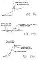
- the deconvolver 30 convolves each multiple-registered video frame with signals, stored in a second memory 36, which represent the inverse of intrinsic point spread function of the aperture of the camera 12. This is illustrated in Fig. 2a which shows the intensity, as a function of position across the image plane of the camera 12, of an original object (solid line) having a sharp edge therein and a blurred image (dashed line) distorted from the original object by the point spread function of the camera 12.
- Fig. 2(b) depicts the high frequencies which will be restored by the convolution process. The result is the enhanced (unblurred) image illustrated in Fig. 2(c) and fed to the second display 18.
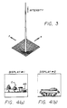
- the deconvolver effectively utilizes a convolution mask of the form shown in Fig. 3 in which the x axis represents the position along a first direction across the image plane of the camera 12 and the y axis represents the position along a second direction, normal to the first direction, across the image plane of the camera 12.
- the z axis represents intensity.
- the mask comprises the negative of the sensor degradation and a positive impulse function on the center pixel of weight 2, the aggregate weight of the entire mask being equivalent to unity.
- the enhancement of the original image provided by the image processor 16 allows for a selected portion of the first image to be magnified with minimal blur.
- the portion of the first image to be magnified and displayed in the second display 18 is selected by the second operator control 22. That is, the second control 22 identifies which subset of the image displayed in display 14 is to be stored in the frame memory 28 and displayed in the second display 18.
- the servo 24 is activated through the multiple image registration circuit 26 to include the object of interest in the cameras field-of-view.
- Figs. 4(a) and 4(b) illustrate the images generated in the first and second displays 14 and 18 by the image processor 16 of the present invention.
- the second image is magnified view of a portion of the first image within the window 40 thereof. Note that the second image is not limited to a field-of-view centered near the center "C" of the first image.
- the present invention has been described herein with refrence to a particular embodiment for a particular application.
- Those having ordinary skill in the art and access to the present teachings will recognize additional modifications applications and embodiments within the scope thereof.
- the invention is not limited to the type of camera or the type of display used therewith.
- the invention is not limited to any particular technique for enhancing the second image.
- the invention is not limited to two displays. Any number of displays and corresponding image processors may utilized as necessary for a particular application.
Abstract
Description
- The present invention relates to imaging systems. More specifically, the present invention relates to systems for providing multiple infrared images.
- While the present invention is described herein with reference to illustrative embodiments for particular applications, it should be understood that the invention is not limited thereto. Those having ordinary skill in the art and access to the teachings provided herein will recognize additional modifications, applications, and embodiments within the scope thereof and additional fields in which the present invention would be of significant utility.
- In many applications, there is a need to provide multiple simultaneous real time images from a single sensor. In forward looking infrared (FLIR) systems, for example, many situations arise in which simultaneous wide angle and zoom views of a scene would be desirable. Previous known attempts to provide such capability have involved two or more sets of lenses and associated optical equipment, one for each field-of-view desired. Typified by boresighted optical fields-of-view, these systems often include an optical field-of-view switch would be activated whenever the operator desired the alternate view. Unfortunately, there are several limitations associated with the simple provision of multiple optical arrangements to provide multiple fields-of-view of an object in real time.
- Multiple optical arrangements can add significantly to the cost, size and weight of an imaging system. (This is particularly problematic with respect to FLIR systems which are generally expensive.) These systems are generally mechanically complex and have close manufacturing tolerances which require precision assembly and maintenance. Further, multiple optical arrangements generally increase the weight on the gimbal supporting the sensor and thereby limit the performance of the host system.
- In addition, to the extent that systems equipped with such multiple optical arrangements provide multiple images of a scene, the zoomed image is generally confined to the center of the wide angle field-of-view. This common boresight limitation prevents a second operator from zooming in on a portion of the image outside of the boresight of the wide angle lens.
- A particularly significant limitation of the multiple optical arrangement approach is that these systems do not provide simultaneous images per se. That is, as only one set of optics may be selected at a time, only one view is available at a time. This is an obvious limitation in situations in which it is desirable to provide a field-of-view for more than one operator at a time. With respect to military equipment, for example, it may be desirable to provide a driver with a wide angle field-of-view and a gunner with a simultaneous zoom view of a particular portion of a scene from the same image sensor.
- An additional limitation of the multiple optical arrangement approach is that the magnification of the lenses is fixed and discretely limited. Only one magnification is available at a time.
- Finally, there are many systems in the field for which this capability would be desirable. Yet the retrofit of existing systems to provide this limited conventional capability would be too expensive to provide a practical option.
- Thus, there is a need in the art for an inexpensive nonmechanical system or technique for providing multiple simultaneous real time images providing diverse fields-of-view of a scene with diverse variable degrees of magnification and without mutual boresight interdependence. Ideally, the system would allow for a ready (noninvasive) retrofit into existing systems and would not degrade the performance thereof.
- The need in the art is addressed by the system of the present invention which provides two separate simultaneous real time images from a single image sensor. The invention is adapted for use with an image sensor which provides a first set of electrical signals in response to electromagnetic energy received thereby from a scene and includes a processor for processing the first set of electrical signals to provide a second set of electrical signals and two displays for providing first and second separate simultaneous real time images in response to the first and second sets of electrical signals respectively.
- In a preferred embodiment, the processor includes circuitry for increasing the spatial sampling rate of the image sensor and a deconvolver for processing the highly sampled signals to generate a second set of electrical signals which when displayed contemporaneously with said first electrical signals, provide an enhanced magnified portion of the sensed scene.
-
- Fig. 1 shows a block diagram of an illustrative embodiment of the imaging system of the present invention.
- Fig. 2(a) shows the intensity, as a function of position across the image plane of the camera utilized in the present invention, of an original image, a blurred image and a reblurred image.
- Fig. 2(b) depicts the high frequencies that will be restored by the convolution process of the present invention.
- Fig. 2(c) shows an enhanced (blur suppressed) image resulting from the deconvolution process employed in the preferred embodiment of the present invention.
- Fig. 3 is a graphic perspective view of a surface corresponding to the convolution mask used by the image processor of the imaging system of the present invention.
- Figs. 4(a) and 4(b) illustrate the images generated in the first and second displays respectively by the image processor utilized in the image system of the present invention.
- Fig. 1 shows a block diagram of an illustrative embodiment of the
imaging system 10 of the present invention. Thesystem 10 includes a conventional camera orvideo imager 12 which provides a first set of electrical output signals representative of electromagnetic energy received thereby from a scene within the field-of-view thereof. Any type of camera or video imager may be used. In the preferred embodiment, the camera orvideo imager 12 is a nonintegrating type imager such as a forward looking infrared (FLIR) sensor. - In the illustrative embodiment of Fig. 1, the output of the
camera 12 is provided to afirst display 14 and to animage processor 16. Thefirst display 14 displays a first image in response to the first electrical signals provided by thecamera 12. As discussed more fully below, theimage processor 16 generates a second set of electrical signals representative of a second image which, in the preferred embodiment, is enhanced to provide a sharp, high resolution, magnified view of a portion of the first image. The output of theprocessor 14 is provided to asecond display 18. Hence, thesecond display 18 displays the second image in response to the second set electrical signals from theprocessor 16. - The invention contemplates the use of first and second operator controls 20 and 22 by first and second operators viewing the first and
second displays camera 12, as shown in thefirst display 14, is determined by thefirst control 20 which controls the pointing angle of thecamera 12 through aconventional servo 24. In accordance with the principles of the present invention, the field-of-view of the second display is selected by thesecond control 22 through theimage processor 16 which in turn controls theservo 24. - In the preferred embodiment, the
image processor 16 increases the sampling rate of thecamera 12 above the Nyquist criterion and deconvolves the highly sampled signals to provide the second set of electrical signals corresponding to the sharp, high resolution, magnified view of a portion of the first image without restriction by the boresight of thecamera 12 to the center of the first image. U. S. Patent No. 4,517,599, issued to Zwirn et al. on May 14, 1985, (the teaching of which is incorporated herein by reference) discloses a technique for processing the output of thecamera 12 to provide such an enhanced image. The increased sampling of the scene is provided by a multipleimage registration circuit 26 which produces a multiple-registered video frame consisting of a plurality of subpixels of reduced area from a plurality of normal video frames provided by thecamera 12. The image motion or camera jitter between subsequent normal video frames determines the subpixel displacement in the multiple-registered video frame. In effect, the multiple image registration circuit forms a mosaic of displaced ones of successive video frames generated by thecamera 12. Implementation of multiple-image registration in already existing system hardware may be accomplished using a correlation tracker, or image motion compensating servo error or camera platform stabilizing gyro error. The multiple image registration circuit typically includes provision for adjusting the address into which correspondingly displaced pixel data are placed. It will be appreciated by those skilled in the art that other techniques may be used to increase the sampling rate of the camera including and the use of smaller detectors to achieve dense sampling in a single frame. - The multiple
image registration circuit 26 is connected to theservo 24 and aframe memory 28. Theframe memory 28 stores the multiple-registered video frames produced by the multipleimage registration circuit 26 for access by adeconvolver 30. Thedeconvolver 30 convolves each multiple-registered video frame with signals, stored in asecond memory 36, which represent the inverse of intrinsic point spread function of the aperture of thecamera 12. This is illustrated in Fig. 2a which shows the intensity, as a function of position across the image plane of thecamera 12, of an original object (solid line) having a sharp edge therein and a blurred image (dashed line) distorted from the original object by the point spread function of thecamera 12. - Fig. 2(b) depicts the high frequencies which will be restored by the convolution process. The result is the enhanced (unblurred) image illustrated in Fig. 2(c) and fed to the
second display 18. - The deconvolver effectively utilizes a convolution mask of the form shown in Fig. 3 in which the x axis represents the position along a first direction across the image plane of the
camera 12 and the y axis represents the position along a second direction, normal to the first direction, across the image plane of thecamera 12. The z axis represents intensity. (As described in the above-identified reference incorporated herein by reference, the mask comprises the negative of the sensor degradation and a positive impulse function on the center pixel ofweight 2, the aggregate weight of the entire mask being equivalent to unity.) - The enhancement of the original image provided by the
image processor 16 allows for a selected portion of the first image to be magnified with minimal blur. The portion of the first image to be magnified and displayed in thesecond display 18 is selected by thesecond operator control 22. That is, thesecond control 22 identifies which subset of the image displayed indisplay 14 is to be stored in theframe memory 28 and displayed in thesecond display 18. When the second operator seeks to view a portion of the scene not within the field-of-view of thecamera 12, theservo 24 is activated through the multipleimage registration circuit 26 to include the object of interest in the cameras field-of-view. - Figs. 4(a) and 4(b) illustrate the images generated in the first and
second displays image processor 16 of the present invention. The second image is magnified view of a portion of the first image within thewindow 40 thereof. Note that the second image is not limited to a field-of-view centered near the center "C" of the first image. - Thus, the present invention has been described herein with refrence to a particular embodiment for a particular application. Those having ordinary skill in the art and access to the present teachings will recognize additional modifications applications and embodiments within the scope thereof. For example, the invention is not limited to the type of camera or the type of display used therewith. Further, the invention is not limited to any particular technique for enhancing the second image. Finally, the invention is not limited to two displays. Any number of displays and corresponding image processors may utilized as necessary for a particular application.
- It is therefore intended by the appended claims to cover any and all such applications, modifications and embodiments within the scope of the present invention.
- Accordingly,
Claims (16)
processing means for processing said first set of electrical signals to provide a second set of electrical signals and
display means for providing first and second separate simultaneous real time images in response to said first and second sets of electrical signals respectively.
sensor means for providing a first set of electrical signals in response to electromagnetic energy received thereby from a scene;
processing means for processing said first set of electrical signals to provide a second set of electrical signals, said processing means including means for enhancing said second image including:
means for effectively increasing a sampling rate of said sensor means,
means for convolving said first set of increased sample rate electrical signals with the inverse of the point spread function associated with the degradations of said sensor means to provide a set of convolved signals; and
display means for providing first and second separate simultaneous real time images in response to said first and second sets of electrical signals respectively.
providing a first set of electrical signals in response to electromagnetic energy from a scene;
processing said first set of electrical signals to provide a second set of electrical signals; and
providing first and second simultaneous real time images in response to said first and second sets of electrical signals respectively.
Applications Claiming Priority (2)
| Application Number | Priority Date | Filing Date | Title |
|---|---|---|---|
| US07/311,785 US4991020A (en) | 1989-02-17 | 1989-02-17 | Imaging system for providing separate simultaneous real time images from a singel image sensor |
| US311785 | 1989-02-17 |
Publications (2)
| Publication Number | Publication Date |
|---|---|
| EP0383113A2 true EP0383113A2 (en) | 1990-08-22 |
| EP0383113A3 EP0383113A3 (en) | 1991-11-27 |
Family
ID=23208461
Family Applications (1)
| Application Number | Title | Priority Date | Filing Date |
|---|---|---|---|
| EP19900102110 Withdrawn EP0383113A3 (en) | 1989-02-17 | 1990-02-02 | Imaging system for providing separate simultaneous real time images from a single image sensor |
Country Status (3)
| Country | Link |
|---|---|
| US (1) | US4991020A (en) |
| EP (1) | EP0383113A3 (en) |
| IL (1) | IL93151A (en) |
Cited By (2)
| Publication number | Priority date | Publication date | Assignee | Title |
|---|---|---|---|---|
| EP0432014A1 (en) * | 1989-12-01 | 1991-06-12 | Thomson-Csf | Optoelectronic assistance system for air-raid missions and navigation |
| GB2249897A (en) * | 1990-12-10 | 1992-05-20 | Hughes Aircraft Co | Multiple simultaneous real-time imaging with selected magnified portions |
Families Citing this family (31)
| Publication number | Priority date | Publication date | Assignee | Title |
|---|---|---|---|---|
| DE3919265A1 (en) * | 1989-06-13 | 1990-12-20 | Krupp Atlas Elektronik Gmbh | OPTO-ELECTRONIC OUTLOOK ASSEMBLY |
| JPH0383460A (en) * | 1989-08-28 | 1991-04-09 | Matsushita Electric Ind Co Ltd | Picture zoom device |
| US5200818A (en) * | 1991-03-22 | 1993-04-06 | Inbal Neta | Video imaging system with interactive windowing capability |
| US7714936B1 (en) | 1991-05-13 | 2010-05-11 | Sony Corporation | Omniview motionless camera orientation system |
| US5384588A (en) * | 1991-05-13 | 1995-01-24 | Telerobotics International, Inc. | System for omindirectional image viewing at a remote location without the transmission of control signals to select viewing parameters |
| US6201574B1 (en) | 1991-05-13 | 2001-03-13 | Interactive Pictures Corporation | Motionless camera orientation system distortion correcting sensing element |
| US6243131B1 (en) | 1991-05-13 | 2001-06-05 | Interactive Pictures Corporation | Method for directly scanning a rectilinear imaging element using a non-linear scan |
| US5903319A (en) * | 1991-05-13 | 1999-05-11 | Interactive Pictures Corporation | Method for eliminating temporal and spacial distortion from interlaced video signals |
| US5138454A (en) * | 1991-09-16 | 1992-08-11 | Eastman Kodak Company | Megapixel video previewer framestore and display |
| US5317395A (en) * | 1993-03-31 | 1994-05-31 | The United States Of America As Represented By The Secretary Of The Army | Focal plane array dual processing system and technique |
| DE69430288T2 (en) * | 1993-10-04 | 2002-10-02 | Canon Kk | Imaging device |
| JP3727954B2 (en) * | 1993-11-10 | 2005-12-21 | キヤノン株式会社 | Imaging device |
| US5547455A (en) * | 1994-03-30 | 1996-08-20 | Medical Media Systems | Electronically steerable endoscope |
| US6476868B1 (en) | 1994-04-11 | 2002-11-05 | Canon Kabushiki Kaisha | Image pickup apparatus provided with enlargement process means for enlarging image signals output from an image pickup device |
| US6493032B1 (en) | 1996-06-24 | 2002-12-10 | Be Here Corporation | Imaging arrangement which allows for capturing an image of a view at different resolutions |
| US6341044B1 (en) | 1996-06-24 | 2002-01-22 | Be Here Corporation | Panoramic imaging arrangement |
| US6373642B1 (en) | 1996-06-24 | 2002-04-16 | Be Here Corporation | Panoramic imaging arrangement |
| US6331869B1 (en) | 1998-08-07 | 2001-12-18 | Be Here Corporation | Method and apparatus for electronically distributing motion panoramic images |
| US6459451B2 (en) | 1996-06-24 | 2002-10-01 | Be Here Corporation | Method and apparatus for a panoramic camera to capture a 360 degree image |
| US6466254B1 (en) | 1997-05-08 | 2002-10-15 | Be Here Corporation | Method and apparatus for electronically distributing motion panoramic images |
| US6356296B1 (en) | 1997-05-08 | 2002-03-12 | Behere Corporation | Method and apparatus for implementing a panoptic camera system |
| EP1064786A4 (en) * | 1998-01-27 | 2005-09-28 | Collaboration Properties Inc | Multifunction video communication service device |
| US6924832B1 (en) | 1998-08-07 | 2005-08-02 | Be Here Corporation | Method, apparatus & computer program product for tracking objects in a warped video image |
| US6369818B1 (en) | 1998-11-25 | 2002-04-09 | Be Here Corporation | Method, apparatus and computer program product for generating perspective corrected data from warped information |
| US6175454B1 (en) | 1999-01-13 | 2001-01-16 | Behere Corporation | Panoramic imaging arrangement |
| US6330373B1 (en) * | 1999-03-05 | 2001-12-11 | The United States Of America As Represented By The Secretary Of The Navy | Real-time detailed scene convolver |
| US20020147991A1 (en) * | 2001-04-10 | 2002-10-10 | Furlan John L. W. | Transmission of panoramic video via existing video infrastructure |
| GB0614567D0 (en) * | 2006-07-21 | 2006-08-30 | Snell & Wilcox Ltd | Motion vector interpolation |
| US9304305B1 (en) * | 2008-04-30 | 2016-04-05 | Arete Associates | Electrooptical sensor technology with actively controllable optics, for imaging |
| US8125559B2 (en) * | 2008-05-25 | 2012-02-28 | Avistar Communications Corporation | Image formation for large photosensor array surfaces |
| US11178349B2 (en) | 2015-01-29 | 2021-11-16 | William Marsh Rice University | Lensless imaging system using an image sensor with one or more attenuating layers |
Citations (1)
| Publication number | Priority date | Publication date | Assignee | Title |
|---|---|---|---|---|
| US4517599A (en) | 1983-01-27 | 1985-05-14 | Hughes Aircraft Company | Resolution enhancement and zoom by degradation estimates |
Family Cites Families (7)
| Publication number | Priority date | Publication date | Assignee | Title |
|---|---|---|---|---|
| DE3146552C2 (en) * | 1981-11-24 | 1983-11-17 | IBP Pietzsch GmbH, 7505 Ettlingen | Method for observation with several recording systems and device for carrying out the method |
| US4574197A (en) * | 1983-03-24 | 1986-03-04 | Hughes Aircraft Company | Dual field of view sensor |
| DE3622618C1 (en) * | 1986-07-05 | 1987-05-21 | Willy Bogner | Method for the simultaneous display of at least two events occurring in succession on the TV and device for carrying out this method |
| US4786966A (en) * | 1986-07-10 | 1988-11-22 | Varo, Inc. | Head mounted video display and remote camera system |
| US4722007A (en) * | 1986-12-02 | 1988-01-26 | Rca Corporation | TV receiver having zoom processing apparatus |
| US4774581A (en) * | 1987-04-14 | 1988-09-27 | Rca Licensing Corporation | Television picture zoom system |
| US4751571A (en) * | 1987-07-29 | 1988-06-14 | General Electric Company | Composite visible/thermal-infrared imaging apparatus |
-
1989
- 1989-02-17 US US07/311,785 patent/US4991020A/en not_active Expired - Fee Related
-
1990
- 1990-01-23 IL IL9315190A patent/IL93151A/en not_active IP Right Cessation
- 1990-02-02 EP EP19900102110 patent/EP0383113A3/en not_active Withdrawn
Patent Citations (1)
| Publication number | Priority date | Publication date | Assignee | Title |
|---|---|---|---|---|
| US4517599A (en) | 1983-01-27 | 1985-05-14 | Hughes Aircraft Company | Resolution enhancement and zoom by degradation estimates |
Cited By (3)
| Publication number | Priority date | Publication date | Assignee | Title |
|---|---|---|---|---|
| EP0432014A1 (en) * | 1989-12-01 | 1991-06-12 | Thomson-Csf | Optoelectronic assistance system for air-raid missions and navigation |
| GB2249897A (en) * | 1990-12-10 | 1992-05-20 | Hughes Aircraft Co | Multiple simultaneous real-time imaging with selected magnified portions |
| GB2249897B (en) * | 1990-12-10 | 1994-10-19 | Hughes Aircraft Co | Imaging system for providing multiple simultaneous real time images |
Also Published As
| Publication number | Publication date |
|---|---|
| IL93151A0 (en) | 1990-11-05 |
| US4991020A (en) | 1991-02-05 |
| EP0383113A3 (en) | 1991-11-27 |
| IL93151A (en) | 1994-11-11 |
Similar Documents
| Publication | Publication Date | Title |
|---|---|---|
| US4991020A (en) | Imaging system for providing separate simultaneous real time images from a singel image sensor | |
| US20040100443A1 (en) | Method and system to allow panoramic visualization using multiple cameras | |
| US9538096B2 (en) | Imaging system and methods with variable lateral magnification | |
| EP0135578B1 (en) | Resolution enhancement and zoom | |
| US7760965B2 (en) | Extended range image processing for electro-optical systems | |
| CN107219710B (en) | Multi-lens system and portable electronic device with same | |
| EP0971540A1 (en) | Omniview motionless camera orientation system | |
| KR20020068330A (en) | Method and apparatus for tracking an object of interest in a digital image | |
| AU567445B2 (en) | Resolution enhancement and zoom by degradation estimates | |
| US5023719A (en) | Imaging system for providing multiple simultaneous real time images | |
| US20230350152A1 (en) | Imaging lens system, image capturing unit and electronic device | |
| US20070064143A1 (en) | Method and system for capturing a wide-field image and a region of interest thereof | |
| Bogner | An introduction to panospheric imaging | |
| US5596365A (en) | Image stabilization apparatus for telescopic devices | |
| GB2249897A (en) | Multiple simultaneous real-time imaging with selected magnified portions | |
| KR20060094957A (en) | Method and system for capturing a wide-field image and a region of interest thereof | |
| US7035479B2 (en) | Graded zooming | |
| CN113973171A (en) | Multi-shooting module, shooting system, electronic equipment and imaging method | |
| JP3604443B2 (en) | Television system | |
| JPH06296252A (en) | Video camera device | |
| CN216210246U (en) | Head-mounted device | |
| Gao et al. | Active aperture control and sensor modulation for flexible imaging | |
| CN217135580U (en) | Optical image stabilization driving device, camera module and electronic device | |
| JPH05183809A (en) | Imaging-system for providing multiple simultaneous real-time image | |
| JP2017212636A (en) | Image processing apparatus, imaging apparatus, and image processing method |
Legal Events
| Date | Code | Title | Description |
|---|---|---|---|
| PUAI | Public reference made under article 153(3) epc to a published international application that has entered the european phase |
Free format text: ORIGINAL CODE: 0009012 |
|
| 17P | Request for examination filed |
Effective date: 19900202 |
|
| AK | Designated contracting states |
Kind code of ref document: A2 Designated state(s): DE ES FR GB NL SE |
|
| PUAL | Search report despatched |
Free format text: ORIGINAL CODE: 0009013 |
|
| AK | Designated contracting states |
Kind code of ref document: A3 Designated state(s): DE ES FR GB NL SE |
|
| 17Q | First examination report despatched |
Effective date: 19940222 |
|
| STAA | Information on the status of an ep patent application or granted ep patent |
Free format text: STATUS: THE APPLICATION IS DEEMED TO BE WITHDRAWN |
|
| 18D | Application deemed to be withdrawn |
Effective date: 19950218 |