EP0384345A1 - Installation for delivering fuel to vehicles - Google Patents
Installation for delivering fuel to vehicles Download PDFInfo
- Publication number
- EP0384345A1 EP0384345A1 EP90103133A EP90103133A EP0384345A1 EP 0384345 A1 EP0384345 A1 EP 0384345A1 EP 90103133 A EP90103133 A EP 90103133A EP 90103133 A EP90103133 A EP 90103133A EP 0384345 A1 EP0384345 A1 EP 0384345A1
- Authority
- EP
- European Patent Office
- Prior art keywords
- gun
- flow
- processor
- trigger
- solenoid valve
- Prior art date
- Legal status (The legal status is an assumption and is not a legal conclusion. Google has not performed a legal analysis and makes no representation as to the accuracy of the status listed.)
- Ceased
Links
Images


Classifications
-
- B—PERFORMING OPERATIONS; TRANSPORTING
- B67—OPENING, CLOSING OR CLEANING BOTTLES, JARS OR SIMILAR CONTAINERS; LIQUID HANDLING
- B67D—DISPENSING, DELIVERING OR TRANSFERRING LIQUIDS, NOT OTHERWISE PROVIDED FOR
- B67D7/00—Apparatus or devices for transferring liquids from bulk storage containers or reservoirs into vehicles or into portable containers, e.g. for retail sale purposes
- B67D7/06—Details or accessories
- B67D7/08—Arrangements of devices for controlling, indicating, metering or registering quantity or price of liquid transferred
- B67D7/28—Arrangements of devices for controlling, indicating, metering or registering quantity or price of liquid transferred with automatic means for reducing or intermittently interrupting flow before completion of delivery, e.g. to produce dribble feed
-
- B—PERFORMING OPERATIONS; TRANSPORTING
- B67—OPENING, CLOSING OR CLEANING BOTTLES, JARS OR SIMILAR CONTAINERS; LIQUID HANDLING
- B67D—DISPENSING, DELIVERING OR TRANSFERRING LIQUIDS, NOT OTHERWISE PROVIDED FOR
- B67D7/00—Apparatus or devices for transferring liquids from bulk storage containers or reservoirs into vehicles or into portable containers, e.g. for retail sale purposes
- B67D7/06—Details or accessories
- B67D7/42—Filling nozzles
- B67D7/44—Filling nozzles automatically closing
- B67D7/46—Filling nozzles automatically closing when liquid in container to be filled reaches a predetermined level
- B67D7/465—Electrical probes sensing the level of the liquid
Definitions
- the present invention relates to a fuel distribution installation for a vehicle.
- the invention aims to allow the automatic full filling of a vehicle tank while avoiding the obligation to maintain manual pressure on the trigger of the gun.
- the invention applies in particular in vehicle depots of public transport companies, in service stations reserved for heavy goods vehicles and also in public service stations.
- the invention thus relates to a fuel distribution installation for a vehicle comprising a distribution terminal, connected to a distributor gun by a flexible pipe, the gun being of the type with manual control by trigger of a shutter shutter and comprising a automatic device for closing said shutter on backflow detection by a backflow detection device, characterized in that it comprises a flow detection device, a programmed processor, and in that the dispensing gun is equipped with a means of actuation of the trigger, controlled by said processor, said processor receiving information from said flow detection device.
- said trigger actuation means comprises a jack acting on a lever in contact with the trigger, said jack being connected to the distribution terminal by a flexible pipe for supplying fluid to the jack, provided with a solenoid valve controlled by said processor.
- the nozzle of the gun is equipped with a hooking mechanism intended to cooperate with a hook, in its open position, for holding in the closed position a closure cap for the vehicle tank.
- the latching mechanism is advantageously provided with a pneumatic contactor interposed in said flexible pipe, between said solenoid valve and the jack, said contactor being actuated at opening when the nozzle of the gun is introduced into the opening of the vehicle tank and the correct attachment of said attachment mechanism on said hook.
- the installation shown comprises a dispensing terminal 1 and a dispensing gun 2 connected to the terminal 1 by a flexible pipe 3 for supplying fuel.
- the dispensing gun is of a well-known conventional type with manual control, by trigger 4, of a shutter flap and comprises an automatic device for closing the shutter flap on detection of backflow by a backflow detection device. This classic system has not been shown.
- the terminal 1 is equipped with a programmed processor 5 and a flow controller 6 placed in the circuit of the product delivered and which delivers to the processor 5 a signal when there is a flow.
- the gun 2 is equipped with a means for actuating the trigger 4 comprising a single-acting cylinder 7 supplied with compressed air by a flexible hose 8.
- the cylinder is provided with a return spring 9 and its rod 10 rests against a bent lever 11 articulated at 12.
- the flexible pipe 8 is provided with a solenoid valve 13 controlled by the processor 5.
- the flexible pipe 8 is supplied with compressed air at 14.
- the operation is as follows: the operator picks up the gun 2 from terminal 1. An electrical signal, indicating that the gun has been off, is transmitted to processor 5 by a contactor located in the gun rest.
- the operator After introduction of the nozzle of the gun into the inlet chute of the tank, the operator starts the flow in the usual way by squeezing the trigger 4 of the gun 2.
- the processor 5 is immediately warned of the flow by the flow detector 6 and controls the opening of the solenoid valve 13.
- the jack supplied with compressed air pushes the lever 11 which switches from keep trigger 4 in the pressed position.
- the operator can then drop the gun and take care of it elsewhere.
- the conventional internal system of the gun ensures in the usual way the stopping of the flow by closing the shutter shutter of the gun.
- the flow stop is then detected by the detector 6 which transmits the information to the processor 5.
- the latter controls the closing of the solenoid valve 13 removing the energy necessary for the jack 7.
- the actuator returns to its rest position and the trigger 4 also.
- the processor 5 again activates the solenoid valve 13, which causes the lever 11 to be pushed and therefore the trigger to operate. 4, thereby restoring the flow.
- the processor 5 is programmed so as to ensure n times.
- the solenoid valve 13 is definitively closed and the operator only has to take out the gun and replace it on its rest on terminal 1.
- the flow detector 6 is replaced by a pulse transmitter 15 which is connected to the axis of the indicator 16 for displaying the volume.
- the gun 2 carries an accessory constituted by an anti-backflow bellows 17 which prevents fuel splashes during the backflows.
- an anti-backflow bellows 17 which prevents fuel splashes during the backflows.
- the gun 2 by its accordion shape whose diameter narrows towards the end of the nozzle of the gun, it allows better maintenance of the gun in the inlet spout of the tank.
- Figure 3 also shows an additional layout.
- the pipe 8 directly feeding the jack 7 after the solenoid valve 13, it comprises between the solenoid valve and the jack, a pneumatic contactor 18 which is fixed to a latching mechanism 19 fixed to the spout 20 gun 2.
- the cylinder is only supplied if the contactor tire 18 is actuated by a pressure exerted on contact 2 of the contactor. This device makes it possible to ensure the flow of the fluid only if the valve 2 is properly inserted and hooked to the inlet of the tank spout.
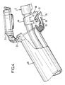
- the attachment mechanism 19 can cooperate for example, see FIG. 4, with a tank cap 22 comprising a tilting cover 23 which, in the closed position, is held by a hook 24 provided with a spring 25. In the open position, the mechanism 19 is hooked onto the hook 24 ensuring the maintenance of the valve 2. A stop 26 limits the tilting of the hook 24. When the valve 2 is properly hooked, the contact 21 is compressed by the upper face of the hook 24 thus allowing the fluid flow if otherwise the solenoid valve 13 is energized.
- the invention makes it possible to refuel fully automatically. Manual operation remains possible, it suffices to provide on the casing 27 containing the processor 5 and the solenoid valve 13 a manual operation control key.
- the system can be easily displayed on all pistols with automatic shutter on the market and it suffices to add on terminal 1 a casing 27 comprising the processor 5 and the solenoid valve 5 and to add a flow detector 6 or a pulse transmitter 15 associated with the volume indicator 16.
- the gun shown in FIG. 3 could also include the anti-backflow accessory constituted by the bellows 17 in FIG. 2.
Abstract
Description
La présente invention concerne une installation de distribution de carburant pour véhicule.The present invention relates to a fuel distribution installation for a vehicle.
Plus précisément, l'invention vise à permettre le plein automatique d'un réservoir de véhicule tout en évitant l'obligation de maintenir la pression manuelle sur la gâchette du pistolet.More specifically, the invention aims to allow the automatic full filling of a vehicle tank while avoiding the obligation to maintain manual pressure on the trigger of the gun.
L'invention s'applique en particulier dans les dépôts de véhicules des sociétés de transport en commun, dans les stations-service réservées au poids lourds et aussi dans les stations-service publiques.The invention applies in particular in vehicle depots of public transport companies, in service stations reserved for heavy goods vehicles and also in public service stations.
L'invention a ainsi pour objet une installation de distribution de carburant pour un véhicule comprenant une borne de distribution, reliée à un pistolet distributeur par une conduite flexible, le pistolet étant du type à commande manuelle par gâchette d'un volet obturateur et comportant un dispositif automatique de fermeture dudit volet sur détection de refoulement par un dispositif de détection de refoulement, caractérisée en ce qu'elle comprend un dispositif de détection de débit, un processeur programmé, et en ce que le pistolet distributeur est équipé d'un moyen d'actionnement de la gâchette, commandé par ledit processeur, ledit processeur recevant des informations dudit dispositif de détection de débit.The invention thus relates to a fuel distribution installation for a vehicle comprising a distribution terminal, connected to a distributor gun by a flexible pipe, the gun being of the type with manual control by trigger of a shutter shutter and comprising a automatic device for closing said shutter on backflow detection by a backflow detection device, characterized in that it comprises a flow detection device, a programmed processor, and in that the dispensing gun is equipped with a means of actuation of the trigger, controlled by said processor, said processor receiving information from said flow detection device.
Selon une réalisation particulière, ledit moyen d'actionnement de la gâchette comprend un vérin agissant sur un levier en contact avec la gâchette, ledit vérin étant relié à la borne de distribution par un tuyau flexible d'alimentation en fluide du vérin, muni d'une électro-vanne commandée par ledit processeur.According to a particular embodiment, said trigger actuation means comprises a jack acting on a lever in contact with the trigger, said jack being connected to the distribution terminal by a flexible pipe for supplying fluid to the jack, provided with a solenoid valve controlled by said processor.
Avantageusement, le bec du pistolet est équipé d'un mécanisme d'accrochage destiné à coopérer avec un crochet, dans sa position ouverte, de maintien en position fermée d'un bouchon de fermeture du réservoir du véhicule.Advantageously, the nozzle of the gun is equipped with a hooking mechanism intended to cooperate with a hook, in its open position, for holding in the closed position a closure cap for the vehicle tank.
Le mécanisme d'accrochage est avantageusement muni d'un contacteur pneumatique intercalé dans ledit tuyau flexible, entre ladite électro-vanne et le vérin, ledit contacteur étant actionné à l'ouverture lors de l'introduction du bec du pistolet dans l'ouverture du réservoir du véhicule et l'accrochage correct dudit mécanisme d'accrochage sur ledit crochet.The latching mechanism is advantageously provided with a pneumatic contactor interposed in said flexible pipe, between said solenoid valve and the jack, said contactor being actuated at opening when the nozzle of the gun is introduced into the opening of the vehicle tank and the correct attachment of said attachment mechanism on said hook.
On va maintenant donner la description d'un exemple de mise en oeuvre de l'invention en se référant au dessin annexé dans lequel :
- - La figure 1 représente une installation de distribution de carburant selon l'invention,
- - la figure 2 représente en vue agrandie le pistolet distributeur de l'installation de la figure 1, muni d'un accessoire,
- - la figure 3 montre également un pistolet distributeur, mais muni d'un aménagement supplémentaire,
- - la figure 4 montre le pistolet distributeur introduit dans l'entrée du réservoir, avec son mécanisme d'accrochage,
- - la figure 5 est une variante de la figure 1.
- FIG. 1 represents a fuel distribution installation according to the invention,
- FIG. 2 represents in enlarged view the dispensing gun of the installation of FIG. 1, provided with an accessory,
- FIG. 3 also shows a dispensing gun, but provided with an additional arrangement,
- FIG. 4 shows the dispensing gun introduced into the inlet of the reservoir, with its attachment mechanism,
- - Figure 5 is a variant of Figure 1.
En se reportant aux figures 1 et 2, l'installation représentée comprend une borne de distribution 1 et un pistolet distributeur 2 relié à la borne 1 par une conduite flexible 3 d'amenée de carburant.Referring to Figures 1 and 2, the installation shown comprises a dispensing terminal 1 and a
Le pistolet distributeur est d'un type classique bien connu à commande manuelle, par gâchette 4, d'un volet obturateur et comprend un dispositif automatique de fermeture du volet obturateur sur détection de refoulement par un dispositif de détection de refoulement. Ce système classique n'a pas été représenté.The dispensing gun is of a well-known conventional type with manual control, by trigger 4, of a shutter flap and comprises an automatic device for closing the shutter flap on detection of backflow by a backflow detection device. This classic system has not been shown.
Conformément à l'invention, la borne 1 est équipée d'un processeur programmé 5 et d'un contrôleur de débit 6 placé dans le circuit du produit délivré et qui délivre au processeur 5 un signal lorsqu'il y a un débit. Par ailleurs, le pistolet 2 est équipé d'un moyen d'actionnement de la gâchette 4 comprenant un vérin 7 à simple effet alimenté en air comprimé par un tuyau flexible 8. Le vérin est muni d'un ressort de rappel 9 et sa tige 10 s'appuie contre un levier coudé 11 articulé en 12. Le tuyau flexible 8 est muni d'une électrovanne 13 commandée par le processeur 5.According to the invention, the terminal 1 is equipped with a programmed processor 5 and a
Le tuyau flexible 8 est alimenté en air comprimé en 14.The
Le fonctionnement est le suivant : l'opérateur décroche le pistolet 2 de la borne 1. Un signal électrique, indiquant que le pistolet a été décroché, est transmis au processeur 5 par un contacteur situé dans le reposoir du pistolet.The operation is as follows: the operator picks up the
Après introduction du bec du pistolet dans la goulotte d'entrée du réservoir, l'opérateur amorce le débit de la manière habituelle en pressant la gâchette 4 du pistolet 2. Le processeur 5 est aussitôt avertit du débit par le détecteur de débit 6 et commande l'ouverture de l'électro-vanne 13. Le vérin, alimenté en air comprimé vient pousser le levier 11 qui bascule venant maintenir la gâchette 4 dans la position pressée.After introduction of the nozzle of the gun into the inlet chute of the tank, the operator starts the flow in the usual way by squeezing the trigger 4 of the
L'opérateur peut alors lâcher le pistolet et s'occuper ailleurs.The operator can then drop the gun and take care of it elsewhere.
Au premier refoulement, le système interne, classique, du pistolet assure de la manière habituelle l'arrêt de l'écoulement par fermeture du volet obturateur du pistolet. L'arrêt du débit est alors détecté par le détecteur 6 qui transmet l'information au processeur 5. Celui-ci commande la fermeture de l'électro-vanne 13 supprimant l'énergie nécessaire au vérin 7. Sous l'action du ressort de rappel 9, le vérin retourne à sa position de repos et la gâchette 4 également. Après une temporisation réglable, de quelques secondes, suffisante pour laisser descendre la mousse occasionnée par les remous du carburant, le processeur 5 active à nouveau l'électro-vanne 13, ce qui provoque la poussée du levier 11 et donc la manoeuvre de la gâchette 4, rétablissant ainsi le débit. Au second refoulement, le même processus se reproduit et le processeur 5 est programmé de façon à assurer ainsi n reprises. Lorsque les n reprises programmées ont été effectuées, l'électro-vanne 13 est définitivement fermée et l'opérateur n'a plus qu'à sortir le pistolet et à la replacer sur son reposoir sur la borne 1.At the first delivery, the conventional internal system of the gun ensures in the usual way the stopping of the flow by closing the shutter shutter of the gun. The flow stop is then detected by the
Sur la figure 5, le détecteur de débit 6 est remplacé par un émetteur d'impulsion 15 qui est branché sur l'axe de l'indicateur 16 d'affichage du volume.In FIG. 5, the
Sur la figure 2 le pistolet 2 porte un accessoire constitué par un soufflet anti-refoulement 17 qui évite les projections de carburant lors des refoulements. En outre, par sa forme en accordéon dont le diamètre se rétrécit vers l'extrémité du bec du pistolet, il permet un meilleur maintien du pistolet dans la goulotte d'entrée du réservoir.In FIG. 2, the
La figure 3 montre également un aménagement supplémentaire. Au lieu que la conduite 8 alimente directement le vérin 7 après l'électro-vanne 13, elle comporte entre l'électro-vanne et le vérin, un contacteur pneumatique 18 qui est fixé sur un mécanisme d'accrochage 19 fixé sur le bec 20 du pistolet 2. Le vérin n'est alimenté que si le contacteur pneumatique 18 est actionné par une pression exercée sur le contact 2 du contacteur. Ce dispositif permet de n'assurer le débit du fluide que si le robinet 2 est bien introduit et accroché à l'entrée de la goulotte du réservoir.Figure 3 also shows an additional layout. Instead of the
Le mécanisme d'accrochage 19 peut coopérer par exemple, voir figure 4, avec un bouchon de réservoir 22 comportant un couvercle basculant 23 qui, en position fermée, est maintenu par un crochet 24 muni d'un ressort 25. En position ouverte, le mécanisme 19 vient s'accrocher sur le crochet 24 assurant le maintien du robinet 2. Une butée 26 limite le basculement du crochet 24. Lorsque le robinet 2 est bien accroché, le contact 21 est comprimé par la face supérieure du crochet 24 permettant ainsi le débit de fluide si par ailleurs l'électro-vanne 13 est excitée.The
Ainsi, l'invention permet de faire le plein complet automatiquement. Le fonctionnement manuel reste possible, il suffit de prévoir sur le caisson 27 renfermant le processeur 5 et l'électro-vanne 13 une touche de commande de fonctionnement manuel.Thus, the invention makes it possible to refuel fully automatically. Manual operation remains possible, it suffices to provide on the
Le système peut se montrer facilement sur tous les pistolets avec clapet d'obturation automatique du commerce et il suffit d'ajouter sur la borne 1 un caisson 27 comportant le processeur 5 et l'électro-vanne 5 et d'ajouter un détecteur de débit 6 ou un émetteur d'impulsions 15 associé à l'indicateur de volume 16.The system can be easily displayed on all pistols with automatic shutter on the market and it suffices to add on terminal 1 a
Bien entendu, le pistolet représenté sur la figure 3 pourrait également comporter l'accessoire anti-refoulement constitué par le soufflet 17 de la figure 2.Of course, the gun shown in FIG. 3 could also include the anti-backflow accessory constituted by the
Claims (6)
Applications Claiming Priority (2)
| Application Number | Priority Date | Filing Date | Title |
|---|---|---|---|
| FR8902232A FR2643355B1 (en) | 1989-02-21 | 1989-02-21 | VEHICLE FUEL DISTRIBUTION SYSTEM |
| FR8902232 | 1989-02-21 |
Publications (1)
| Publication Number | Publication Date |
|---|---|
| EP0384345A1 true EP0384345A1 (en) | 1990-08-29 |
Family
ID=9378975
Family Applications (1)
| Application Number | Title | Priority Date | Filing Date |
|---|---|---|---|
| EP90103133A Ceased EP0384345A1 (en) | 1989-02-21 | 1990-02-19 | Installation for delivering fuel to vehicles |
Country Status (2)
| Country | Link |
|---|---|
| EP (1) | EP0384345A1 (en) |
| FR (1) | FR2643355B1 (en) |
Citations (4)
| Publication number | Priority date | Publication date | Assignee | Title |
|---|---|---|---|---|
| DE938473C (en) * | 1953-10-25 | 1956-02-02 | Erich Goedecke | System for refueling motor vehicles with tap and filling hose |
| US3916961A (en) * | 1973-03-26 | 1975-11-04 | Lawrence Dilger | Liquid dispensing apparatus |
| GB2081222A (en) * | 1980-08-01 | 1982-02-17 | Pandrol Ltd | Fuel delivery device |
| EP0065117A2 (en) * | 1981-05-05 | 1982-11-24 | BASF Aktiengesellschaft | Automatically closing tap |
-
1989
- 1989-02-21 FR FR8902232A patent/FR2643355B1/en not_active Expired - Fee Related
-
1990
- 1990-02-19 EP EP90103133A patent/EP0384345A1/en not_active Ceased
Patent Citations (4)
| Publication number | Priority date | Publication date | Assignee | Title |
|---|---|---|---|---|
| DE938473C (en) * | 1953-10-25 | 1956-02-02 | Erich Goedecke | System for refueling motor vehicles with tap and filling hose |
| US3916961A (en) * | 1973-03-26 | 1975-11-04 | Lawrence Dilger | Liquid dispensing apparatus |
| GB2081222A (en) * | 1980-08-01 | 1982-02-17 | Pandrol Ltd | Fuel delivery device |
| EP0065117A2 (en) * | 1981-05-05 | 1982-11-24 | BASF Aktiengesellschaft | Automatically closing tap |
Also Published As
| Publication number | Publication date |
|---|---|
| FR2643355B1 (en) | 1991-04-19 |
| FR2643355A1 (en) | 1990-08-24 |
Similar Documents
| Publication | Publication Date | Title |
|---|---|---|
| EP1111241B1 (en) | Pressurised dispenser and compressed air recharging station therefor | |
| EP0384345A1 (en) | Installation for delivering fuel to vehicles | |
| EP0778052A1 (en) | Fire extinguishing apparatus and cradle for securing the same on a support | |
| EP0685605A1 (en) | Toilet flushing device with double actuation button allowing the delivery of a predetermined flush quantity | |
| FR2581597A1 (en) | Device for limiting the filling of a fuel tank, especially for a motor vehicle | |
| FR2467800A1 (en) | DEVICE FOR LIMITING THE FILLING HEIGHT OF A RECEPTACLE TO BE CHARGED | |
| FR2724958A1 (en) | Water distributor for WC | |
| US3589413A (en) | Automatic liquid dispensing nozzle | |
| EP0983962B1 (en) | Beverage dispenser with control of the presence of beverage holding container | |
| FR2775274A1 (en) | Portable unit for remote control of filling of tanks or barrels, particularly with wine | |
| FR2651766A1 (en) | Device for blocking the manoeuvring grip of a fuel dispensing nozzle | |
| EP1945511B1 (en) | Installation for filling a container, in particular an aerosol container | |
| FR2793450A1 (en) | Fuel tank for motor vehicle comprises flexible bladder inside rigid shell and has pressurization system for space between bladder and shell to direct fuel through pipe to engine | |
| FR2784357A1 (en) | Liquid dispenser providing frosting on the inside of a drinking glass, uses a freezer which sprays a refrigerated gas jet into the glass | |
| EP2236680B1 (en) | Double flow flushing system with magnetic valve | |
| EP0738523B1 (en) | Safety against rearming for fire extinguishing heads | |
| EP0774373B1 (en) | Arrangement for filling a motor vehicle fuel tank | |
| EP0313471A1 (en) | Automatic ice cube dispenser | |
| FR3103186A1 (en) | Receptacle for cryogenic connector | |
| FR2725974A1 (en) | Control of fuel delivery pump at filling stations | |
| CA2210210C (en) | Coin operated fluid dispenser system | |
| FR2712579A1 (en) | Automatic filler for supple containers designed to hold liq. food products | |
| FR2746089A1 (en) | Fuel dispensing nozzle adaptor | |
| FR2629948A3 (en) | Float device for filling storage batteries with distilled water and checking level | |
| FR2762378A1 (en) | Filler for portable gas cylinder |
Legal Events
| Date | Code | Title | Description |
|---|---|---|---|
| PUAI | Public reference made under article 153(3) epc to a published international application that has entered the european phase |
Free format text: ORIGINAL CODE: 0009012 |
|
| AK | Designated contracting states |
Kind code of ref document: A1 Designated state(s): BE DE ES FR IT LU NL |
|
| 17P | Request for examination filed |
Effective date: 19910225 |
|
| 17Q | First examination report despatched |
Effective date: 19931022 |
|
| STAA | Information on the status of an ep patent application or granted ep patent |
Free format text: STATUS: THE APPLICATION HAS BEEN REFUSED |
|
| 18R | Application refused |
Effective date: 19940418 |