EP0385604B1 - Surgical needle and localisation needle assembly - Google Patents
Surgical needle and localisation needle assembly Download PDFInfo
- Publication number
- EP0385604B1 EP0385604B1 EP90301511A EP90301511A EP0385604B1 EP 0385604 B1 EP0385604 B1 EP 0385604B1 EP 90301511 A EP90301511 A EP 90301511A EP 90301511 A EP90301511 A EP 90301511A EP 0385604 B1 EP0385604 B1 EP 0385604B1
- Authority
- EP
- European Patent Office
- Prior art keywords
- needle
- wire
- cannula
- distal end
- localisation
- Prior art date
- Legal status (The legal status is an assumption and is not a legal conclusion. Google has not performed a legal analysis and makes no representation as to the accuracy of the status listed.)
- Expired - Lifetime
Links
Images

Classifications
-
- A—HUMAN NECESSITIES
- A61—MEDICAL OR VETERINARY SCIENCE; HYGIENE
- A61B—DIAGNOSIS; SURGERY; IDENTIFICATION
- A61B90/00—Instruments, implements or accessories specially adapted for surgery or diagnosis and not covered by any of the groups A61B1/00 - A61B50/00, e.g. for luxation treatment or for protecting wound edges
- A61B90/39—Markers, e.g. radio-opaque or breast lesions markers
-
- A—HUMAN NECESSITIES
- A61—MEDICAL OR VETERINARY SCIENCE; HYGIENE
- A61B—DIAGNOSIS; SURGERY; IDENTIFICATION
- A61B90/00—Instruments, implements or accessories specially adapted for surgery or diagnosis and not covered by any of the groups A61B1/00 - A61B50/00, e.g. for luxation treatment or for protecting wound edges
- A61B90/06—Measuring instruments not otherwise provided for
- A61B2090/062—Measuring instruments not otherwise provided for penetration depth
-
- A—HUMAN NECESSITIES
- A61—MEDICAL OR VETERINARY SCIENCE; HYGIENE
- A61B—DIAGNOSIS; SURGERY; IDENTIFICATION
- A61B90/00—Instruments, implements or accessories specially adapted for surgery or diagnosis and not covered by any of the groups A61B1/00 - A61B50/00, e.g. for luxation treatment or for protecting wound edges
- A61B90/39—Markers, e.g. radio-opaque or breast lesions markers
- A61B2090/3904—Markers, e.g. radio-opaque or breast lesions markers specially adapted for marking specified tissue
- A61B2090/3908—Soft tissue, e.g. breast tissue
-
- A—HUMAN NECESSITIES
- A61—MEDICAL OR VETERINARY SCIENCE; HYGIENE
- A61B—DIAGNOSIS; SURGERY; IDENTIFICATION
- A61B90/00—Instruments, implements or accessories specially adapted for surgery or diagnosis and not covered by any of the groups A61B1/00 - A61B50/00, e.g. for luxation treatment or for protecting wound edges
- A61B90/39—Markers, e.g. radio-opaque or breast lesions markers
- A61B2090/3925—Markers, e.g. radio-opaque or breast lesions markers ultrasonic
-
- A—HUMAN NECESSITIES
- A61—MEDICAL OR VETERINARY SCIENCE; HYGIENE
- A61B—DIAGNOSIS; SURGERY; IDENTIFICATION
- A61B90/00—Instruments, implements or accessories specially adapted for surgery or diagnosis and not covered by any of the groups A61B1/00 - A61B50/00, e.g. for luxation treatment or for protecting wound edges
- A61B90/39—Markers, e.g. radio-opaque or breast lesions markers
- A61B2090/3937—Visible markers
-
- A—HUMAN NECESSITIES
- A61—MEDICAL OR VETERINARY SCIENCE; HYGIENE
- A61M—DEVICES FOR INTRODUCING MEDIA INTO, OR ONTO, THE BODY; DEVICES FOR TRANSDUCING BODY MEDIA OR FOR TAKING MEDIA FROM THE BODY; DEVICES FOR PRODUCING OR ENDING SLEEP OR STUPOR
- A61M25/00—Catheters; Hollow probes
- A61M25/01—Introducing, guiding, advancing, emplacing or holding catheters
- A61M25/09—Guide wires
- A61M2025/09191—Guide wires made of twisted wires
Definitions
- This invention relates to a surgical needle and to a localisation needle assembly, comprising a combination of the surgical needle and an outer tubular cannula member, which may be readily inserted into and anchored within body tissue to identify to the surgeon the location of non-palpable lesions.
- a hypodermic needle is initially placed into the breast to locate the breast lesion.
- a stainless steel wire having a hairpin hooked-end portion is slid through the needle wherein the hooked hairpin-end portion exits from the needle to engage the body tissue to retain the needle adjacent to, or at, the breast lesion.
- the introducing needle is withdrawn over the wire and the wire is anchored to the tissue and the patient is taken to surgery.
- the wire permits the surgeon to know where the lesion lies within the breast tissue.
- this known needle and wire-hook arrangement possesses several disadvantages.
- the breast is compressed which can cause the needle to move or be displaced with respect to the breast lesion.
- an additional set of mammograms is required to verify the positioning of the needle within the breast tissue. If the position is incorrect, the hooked wire cannot be easily removed and forceful removal results in considerable damage to the tissue, the final removal of the hooked end from the breast causing undesirable tearing and damage to the breast tissue.
- Another known needle/wire device and technique includes a curved-end wire which is made of a tough pseudo-elastic alloy which possesses a memory.
- a needle containing a wire having a J-shaped hook on the end is inserted into the breast and advanced to identify the location of the breast lesion.
- the wire is then advanced inwardly such that the curved hooked end engages the body tissue to immobilise the needle during mammography imaging to ensure that the needle is correctly positioned at or adjacent the breast lesion.
- the needle and hook device can be relatively easily displaced if traction or pressure is applied to the breast during transport of the patient or during surgery. Thus actual migration of the hook-wire device in the breast tissue occurs during movement of the patient to surgery and during the actual surgery.
- Both these known systems employ a single wire needle for anchoring the localisation needle assembly to body tissue.
- the wire needle must be flexible and pliable to allow easy handling and fastening of the proximal end of the wire outside of the patient's body and to resist the risk of unintended penetration or migration.
- the needle wire must be sufficiently large so as to resist accidental transection by the surgeon during excision, this limits the amount of flexibility and pliability obtainable for known needle anchoring arrangements which employ a single wire.
- a further known surgical needle is disclosed in US-A-4774948.
- a separate protective sheath is provided around a linear distal end portion of the needle.
- This sheath in tubular form acts as protection for the end portion of the needle and is not intended primarily to serve as reinforcement for the needle end portion.
- Another object of the present invention is to provide a localisation needle assembly incorporating a needle structure which may be readily positioned and anchored within body tissue to precisely locate and pinpoint lesions for subsequent surgical removal or biopsy.
- a localisation needle assembly 10 provided in accordance with the present invention for use in locating lesions within body tissue, and in particular for use as a breast localisation needle assembly for locating non-palpable lesions within the breast.
- the localisation needle assembly 10 is specifically described with reference to an application as a breast localisation assembly, the localisation needle assembly 10 of the present invention has application in locating cancerous non-palpable lesions within the human or animal body, be it a brain tumor, or any medical procedure which requires the pinpointing of a lesion, foreign body or normal structure within the body or organ of the body.
- the localisation needle assembly 10 includes a tubular outer cannula 11 and a surgical needle having a needle structure 12 which is adapted for sliding movement within the outer cannula 11.
- the needle structure 12 defines a retractable barb 13, shown deployed in Figure 1, whereby the barb 13 projects outwardly through an aperture 14 in the outer cannula 11 for anchoring the localisation needle assembly to body tissue as will be described hereinafter.
- the barb 13 is retracted within the outer cannula 11 during introduction of the needle guide assembly into the patient's body during localisation procedures, and is deployed by withdrawing the wire structure by pulling on its proximal end for immobilising the needle during mammography.
- the needle structure 12 has markings 29 and 29a thereon to provide an indication to the user as to the location of the tip and barb relative to the tip and aperture ( Figure 1) of the cannula 11.
- the markings enable the surgeon to know when the barb is retracted and when it is deployed. For example, marking 29 when aligned with the proximal edge 11a of the cannula indicates that the barb is retracted within the cannula 11.
- the marking 29a when aligned with the proximal edge 11a of the cannula 11, indicates that the barb is fully deployed.
- the needle structure 12 has a proximal end 14′ and a distal end 15.
- the needle structure 12 is formed of an elongate single wire 16 which is reinforced over a portion of its length with multiple wire strands 17 to form a unitary needle wire structure.
- the outer wires 17 may be wound (or stranded) in helical fashion around the core wire 16, but terminate short of the distal end of the core wire 16, defining a junction point 18 at which point the outer wires 17 are connected or secured to the core wire 16 in a suitable manner such as by solder.
- a further solder joint 19 is provided at the tip of the needle structure 11 at the proximal end 14′ thereof. These solder connections protect the wire 11 from fraying at the proximal end 14′ and at the junction point 18.
- the distal tip portion of the core wire 16 is bent over on itself and tightened, as is known in the art, to form the barb portion 13 which projects rearwardly from the distal tip, that is, toward the right in Figure 2, and terminates in a sharp tip or point 20.
- the overbend may be secured as by solder 20a.
- the use of reinforcement permits the needle structure 12 to be made of a smaller diameter wire to enhance the flexibility and pliability of the needle structure without compromising its resistance to accidental transection.
- the reinforcement is provided by the multiple wire strands 17 which may be wound or stranded on the core wire 16 over a portion of its length.
- the outer wires 17 may be wrapped on the core wire 16 and/or may be braided before being combined with the core wire.
- wires of circular cross-section are illustrated, the outer wire or wires could be in the form of a flat band or strip having a rectangular cross-section.
- the core wire 16 illustrated in Figure 2 is a single wire element, the core wire may comprise a two element structure 30 such as that illustrated in Figure 3 wherein an inner cannula 33 is secured to the distal end of the core wire 16 as will be described.
- the reinforcement for a needle structure 40 is provided by coiling the core wire over a portion of its length as will hereinafter be described.
- the stranded needle structures 12 and 30 illustrated in Figures 2 and 3 may take various forms.
- the needle wire structure 12 may comprise a core wire 16 on which may be wound or stranded a plurality of outer wires 17, there being twelve wires 17 illustrated in Figure 5.
- the needle structure 12a includes twelve outer wires 22 wrapped around six intermediate wires 23 wrapped around a single core wire 16.
- a needle structure 12b includes a single core wire 16 upon which are wrapped six strands 24 each including seven wires 25.
- the core 16′ comprises a stranded wire including three wires 27 upon which are wound or stranded nine outer wires 28.
- the stranded configuration for the needle structure 12 provides reinforcement for the needle structure along substantially its entire length providing many advantages over a conventional wire needle. For example, multiple strands resist accidental transection. Even if several strands were to be cut, functionality of the needle structure would be preserved. Also, strands are more flexible than stiff single wires and the use of strands reduces risk of additional penetration of organs or vessels or migration within cavity due to accidental contact with the needle assembly during normal movement of the patient during diagnostic procedures as during the transportation of the patient to surgery. The flexibility and pliability allow easier handling of the wire structure outside of the patient's body and fastening of the wire structure to the patient's skin with adhesive tape. Moreover, a larger strand has greater tensile strength than a single small diameter wire, and strands resist fatigue breakage better than does a single wire.
- a stranded needle structure 30 having a proximal end 31 and a distal end 32 and which includes a short inner cannula member 33 which is attached to the core wire 16 at its end 35.
- the needle structure 30 further includes a short wire member 36, the forward end 36a of which is secured to the inner cannula member 33 by soldering, welding, by adhesive or by mechanical means, such as, crimping, threading or shrinking.
- the short wire member 36 includes a free end 37 defining a barb or hook which is adapted to anchor the needle within body tissue.
- a further embodiment of a needle structure 40 includes a linear portion 41 at its distal end 42 and a helical portion 43 intermediate its proximal end 44 and its distal end 42, and preferably extending all the way to its proximal end.
- the needle structure 40 may be formed of a single wire or monofilament which is coiled from the linear portion 41 to its proximal end. The tip of the wire is folded back upon itself to define a rearwardly projecting barb 45.
- the helical coiled portion 43 defines the reinforcement for the needle structure 40 while permitting use of a single wire or monofilament. This configuration provides a degree of rigidity of the needle structure in the distal end portion, permitting the barb to anchor the localisation needle assembly to body tissue, and with the proximal end portion or helical coiled portion 43 providing flexibility and pliability in the portion of the structure by which the user directs the anchoring distal end to the target.
- the outer cannula 11 includes a hollow tubular shaft portion 51 having a proximal end 52 and a distal end 53.
- the cannula may be comprised of a rigid material composed of either steel, polymer or a combination thereof and may be of a variable length as required.
- a hub 54 is mounted on the proximal end of the shaft 51 to facilitate use of the cannula.
- the distal end 53 is provided with a sharp point 55.
- the tubular shaft 51 has an opening 14 formed therethrough at a predetermined distance from the tip 55 of the cannula. Markings 58 are provided on the outer surface of the cannula 11 to provide an indication to the surgeon of the depth to which the cannula has been inserted into the body of the patient being treated.
- the use of the localisation needle assembly provided by the present invention is described with reference to an embodiment for the assembly 60 illustrated in Figures 10, 10A and 11 which includes the needle structure 30 illustrated in Figure 3 assembled within the outer cannula 11 illustrated in Figure 9.
- the needle structures 12 and 40 illustrated in Figures 2 and 4 would function in a similar manner in localisation procedures.
- the barb 36 is illustrated in a retracted position within the bore 57 forward of the opening 14 with the barb 36 engaging the inner wall 59 of the tubular shaft 51.
- the needle assembly 60 is illustrated with the barb 36 in an extended position in which the needle wire structure 30 has been withdrawn back into the cannula 11, moving the inner cannula 33 towards the right in Figures 11 and 11A, permitting the barb 36 to pass through the opening 14 in the cannula 11 for deployment.
- the needle structure 30 is positioned within cannula 11 so that the tip of the needle structure 30 extends outwardly of the cannula 11 at the distal end 55 of the cannula 11 such that the barb 36 is retracted during insertion of the assembly into the tissue of the body.
- the localisation needle assembly 60 is advanced to the target area of a human or animal body, either for simply marking the location, be it the breast, liver, ductal structure, brain, lung or other organs where it is desirable to take a biopsy, a sample structure or to surgically remove an unwanted mass or lesion from the body.
- the desired position is obtained by advancing the needle assembly into the target area using the forward pressure on the hub on the cannula 11 to advance the localisation needle assembly 60 into the target.
- the inner needle assembly 30 is withdrawn back into the cannula thereby deploying the barb 36 through opening 14 in the sidewall of the cannula 11 to lock and firmly anchor the localisation needle assembly 60 in position within the body tissue, immobilising the assembly 60.
- the localisation needle assembly 60 has been inserted into the breast, the movement of the barb 36 into the body tissue anchors and firmly retains the needle assembly within the breast or body tissue.
- the opening 14 may be located on the outer cannula at a position where it is desired that the needle assembly be anchored to the body tissue. Preferably this position is adjacent the distal end, but it could be located at any position intermediate the distal and proximal ends provided proper anchoring of the localisation needle assembly occurs with respect to the body tissue.
- the barb 36 can be retracted by advancing the stranded needle and the inner cannula attached thereto into the outer cannula 11.
- the localisation needle assembly 60 can then be repositioned to locate the lesion, the inner cannula 33 being moved outwardly of the outer cannula 11 to again deploy the barb 36 when the lesion is located.
- the length of the outer cannula can vary depending upon the depth of the lesion that is to be localised and identified for subsequent surgical operation.
Abstract
Description
- This invention relates to a surgical needle and to a localisation needle assembly, comprising a combination of the surgical needle and an outer tubular cannula member, which may be readily inserted into and anchored within body tissue to identify to the surgeon the location of non-palpable lesions.
- Various localisation needle systems have been proposed to aid the surgeon in locating non-palpable lesions within the breast. In one system, commonly referred to as a needle and hook-wire system, a hypodermic needle is initially placed into the breast to locate the breast lesion. When the needle is properly placed, a stainless steel wire having a hairpin hooked-end portion is slid through the needle wherein the hooked hairpin-end portion exits from the needle to engage the body tissue to retain the needle adjacent to, or at, the breast lesion. The introducing needle is withdrawn over the wire and the wire is anchored to the tissue and the patient is taken to surgery. The wire permits the surgeon to know where the lesion lies within the breast tissue.
- However, this known needle and wire-hook arrangement possesses several disadvantages. For example, during mammographic filming of the breast lesion and the location of the needle within the breast, the breast is compressed which can cause the needle to move or be displaced with respect to the breast lesion. Additionally, after the hairpin hooked-end wire portion has been inserted through the needle and expanded to anchor the needle/hooked end apparatus in place, an additional set of mammograms is required to verify the positioning of the needle within the breast tissue. If the position is incorrect, the hooked wire cannot be easily removed and forceful removal results in considerable damage to the tissue, the final removal of the hooked end from the breast causing undesirable tearing and damage to the breast tissue.
- Another known needle/wire device and technique includes a curved-end wire which is made of a tough pseudo-elastic alloy which possesses a memory. A needle containing a wire having a J-shaped hook on the end is inserted into the breast and advanced to identify the location of the breast lesion. The wire is then advanced inwardly such that the curved hooked end engages the body tissue to immobilise the needle during mammography imaging to ensure that the needle is correctly positioned at or adjacent the breast lesion. The needle and hook device can be relatively easily displaced if traction or pressure is applied to the breast during transport of the patient or during surgery. Thus actual migration of the hook-wire device in the breast tissue occurs during movement of the patient to surgery and during the actual surgery.
- Both these known systems employ a single wire needle for anchoring the localisation needle assembly to body tissue. The wire needle must be flexible and pliable to allow easy handling and fastening of the proximal end of the wire outside of the patient's body and to resist the risk of unintended penetration or migration. However, because the needle wire must be sufficiently large so as to resist accidental transection by the surgeon during excision, this limits the amount of flexibility and pliability obtainable for known needle anchoring arrangements which employ a single wire.
- A further known surgical needle is disclosed in US-A-4774948. In this known needle, a separate protective sheath is provided around a linear distal end portion of the needle. This sheath in tubular form acts as protection for the end portion of the needle and is not intended primarily to serve as reinforcement for the needle end portion.
- It is an object of the present invention to provide a reinforced surgical needle for a localisation needle assembly which has greater flexibility and pliability than that for known comparable sized needles and which resists accidental transection.
- Another object of the present invention is to provide a localisation needle assembly incorporating a needle structure which may be readily positioned and anchored within body tissue to precisely locate and pinpoint lesions for subsequent surgical removal or biopsy.
- According to one aspect of the present invention there is provided a surgical needle as claimed in the ensuing claim 1.
- According to another aspect of the present invention there is provided a localisation needle assembly as claimed in the ensuing claim 11.
- Embodiments of the invention will now be described, by way of example, with reference to the accompanying drawings, in which:
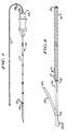
- Figure 1 is a side view of a localisation needle assembly provided by the present invention,
- Figure 2 is an enlarged side view of an inner needle structure of the localisation needle assembly shown in Figure 1,
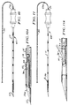
- Figure 3 is an enlarged side view of a further embodiment of an inner needle structure for a localisation needle assembly provided by the present invention,
- Figure 4 is an enlarged side view of another embodiment of an inner needle structure of a localisation needle assembly,
- Figures 5 to 8 are cross-sectional views for various embodiments of the needle structure illustrated in Figures 2 and 3,
- Figure 9 is a side view of an outer cannula of the localisation needle assembly shown in Figure 1,
- Figure 10 is a side view of the localisation needle assembly provided by the present invention with the anchoring barb illustrated in its retracted position,
- Figure 10A is an enlarged fragmentary view of the distal end of the localisation needle assembly illustrated in Figure 10,
- Figure 11 is a side view of the localisation needle assembly of Figure 10, but illustrated with the anchoring barb employed, and
- Figure 11A is an enlarged fragmentary view of the distal end of the localisation needle assembly of Figure 11.
- Referring to Figure 1, there is illustrated a
localisation needle assembly 10 provided in accordance with the present invention for use in locating lesions within body tissue, and in particular for use as a breast localisation needle assembly for locating non-palpable lesions within the breast. Although thelocalisation needle assembly 10 is specifically described with reference to an application as a breast localisation assembly, thelocalisation needle assembly 10 of the present invention has application in locating cancerous non-palpable lesions within the human or animal body, be it a brain tumor, or any medical procedure which requires the pinpointing of a lesion, foreign body or normal structure within the body or organ of the body. - The
localisation needle assembly 10 includes a tubular outer cannula 11 and a surgical needle having aneedle structure 12 which is adapted for sliding movement within the outer cannula 11. Theneedle structure 12 defines aretractable barb 13, shown deployed in Figure 1, whereby thebarb 13 projects outwardly through anaperture 14 in the outer cannula 11 for anchoring the localisation needle assembly to body tissue as will be described hereinafter. Thebarb 13 is retracted within the outer cannula 11 during introduction of the needle guide assembly into the patient's body during localisation procedures, and is deployed by withdrawing the wire structure by pulling on its proximal end for immobilising the needle during mammography. - The
needle structure 12 hasmarkings 29 and 29a thereon to provide an indication to the user as to the location of the tip and barb relative to the tip and aperture (Figure 1) of the cannula 11. The markings enable the surgeon to know when the barb is retracted and when it is deployed. For example, marking 29 when aligned with the proximal edge 11a of the cannula indicates that the barb is retracted within the cannula 11. The marking 29a, when aligned with the proximal edge 11a of the cannula 11, indicates that the barb is fully deployed. - Referring to Figure 2, the
needle structure 12 has aproximal end 14′ and a distal end 15. Theneedle structure 12 is formed of an elongatesingle wire 16 which is reinforced over a portion of its length withmultiple wire strands 17 to form a unitary needle wire structure. As illustrated in Figure 2, for example, theouter wires 17 may be wound (or stranded) in helical fashion around thecore wire 16, but terminate short of the distal end of thecore wire 16, defining ajunction point 18 at which point theouter wires 17 are connected or secured to thecore wire 16 in a suitable manner such as by solder. A further solder joint 19 is provided at the tip of the needle structure 11 at theproximal end 14′ thereof. These solder connections protect the wire 11 from fraying at theproximal end 14′ and at thejunction point 18. - The distal tip portion of the
core wire 16 is bent over on itself and tightened, as is known in the art, to form thebarb portion 13 which projects rearwardly from the distal tip, that is, toward the right in Figure 2, and terminates in a sharp tip orpoint 20. The overbend may be secured as bysolder 20a. The use of reinforcement permits theneedle structure 12 to be made of a smaller diameter wire to enhance the flexibility and pliability of the needle structure without compromising its resistance to accidental transection. - For the
needle structure 12 illustrated in Figure 2, the reinforcement is provided by themultiple wire strands 17 which may be wound or stranded on thecore wire 16 over a portion of its length. Theouter wires 17 may be wrapped on thecore wire 16 and/or may be braided before being combined with the core wire. Moreover, although wires of circular cross-section are illustrated, the outer wire or wires could be in the form of a flat band or strip having a rectangular cross-section. Also, although thecore wire 16 illustrated in Figure 2 is a single wire element, the core wire may comprise a twoelement structure 30 such as that illustrated in Figure 3 wherein aninner cannula 33 is secured to the distal end of thecore wire 16 as will be described. Further, as illustrated in Figure 4, the reinforcement for a needle structure 40 is provided by coiling the core wire over a portion of its length as will hereinafter be described. - The stranded
needle structures needle wire structure 12 may comprise acore wire 16 on which may be wound or stranded a plurality ofouter wires 17, there being twelvewires 17 illustrated in Figure 5. - Referring to Figure 6, in a further embodiment, the needle structure 12a includes twelve
outer wires 22 wrapped around sixintermediate wires 23 wrapped around asingle core wire 16. In Figure 7, aneedle structure 12b includes asingle core wire 16 upon which are wrapped sixstrands 24 each including sevenwires 25. In another embodiment for awire structure 12c shown in Figure 8, thecore 16′ comprises a stranded wire including threewires 27 upon which are wound or stranded nine outer wires 28. - The stranded configuration for the
needle structure 12 provides reinforcement for the needle structure along substantially its entire length providing many advantages over a conventional wire needle. For example, multiple strands resist accidental transection. Even if several strands were to be cut, functionality of the needle structure would be preserved. Also, strands are more flexible than stiff single wires and the use of strands reduces risk of additional penetration of organs or vessels or migration within cavity due to accidental contact with the needle assembly during normal movement of the patient during diagnostic procedures as during the transportation of the patient to surgery. The flexibility and pliability allow easier handling of the wire structure outside of the patient's body and fastening of the wire structure to the patient's skin with adhesive tape. Moreover, a larger strand has greater tensile strength than a single small diameter wire, and strands resist fatigue breakage better than does a single wire. - Referring to Figure 3, there is illustrated a further embodiment for a stranded
needle structure 30 having a proximal end 31 and a distal end 32 and which includes a shortinner cannula member 33 which is attached to thecore wire 16 at its end 35. Theneedle structure 30 further includes ashort wire member 36, theforward end 36a of which is secured to theinner cannula member 33 by soldering, welding, by adhesive or by mechanical means, such as, crimping, threading or shrinking. Theshort wire member 36 includes afree end 37 defining a barb or hook which is adapted to anchor the needle within body tissue. - Referring to Figure 4, a further embodiment of a needle structure 40 includes a
linear portion 41 at its distal end 42 and a helical portion 43 intermediate itsproximal end 44 and its distal end 42, and preferably extending all the way to its proximal end. The needle structure 40 may be formed of a single wire or monofilament which is coiled from thelinear portion 41 to its proximal end. The tip of the wire is folded back upon itself to define a rearwardly projecting barb 45. - The helical coiled portion 43 defines the reinforcement for the needle structure 40 while permitting use of a single wire or monofilament. This configuration provides a degree of rigidity of the needle structure in the distal end portion, permitting the barb to anchor the localisation needle assembly to body tissue, and with the proximal end portion or helical coiled portion 43 providing flexibility and pliability in the portion of the structure by which the user directs the anchoring distal end to the target.
- Referring to Figure 9, the outer cannula 11 includes a hollow
tubular shaft portion 51 having a proximal end 52 and a distal end 53. The cannula may be comprised of a rigid material composed of either steel, polymer or a combination thereof and may be of a variable length as required. Ahub 54 is mounted on the proximal end of theshaft 51 to facilitate use of the cannula. The distal end 53 is provided with a sharp point 55. Thetubular shaft 51 has anopening 14 formed therethrough at a predetermined distance from the tip 55 of the cannula.Markings 58 are provided on the outer surface of the cannula 11 to provide an indication to the surgeon of the depth to which the cannula has been inserted into the body of the patient being treated. - The use of the localisation needle assembly provided by the present invention is described with reference to an embodiment for the
assembly 60 illustrated in Figures 10, 10A and 11 which includes theneedle structure 30 illustrated in Figure 3 assembled within the outer cannula 11 illustrated in Figure 9. However, theneedle structures 12 and 40 illustrated in Figures 2 and 4, would function in a similar manner in localisation procedures. In Figures 10 and 10A, thebarb 36 is illustrated in a retracted position within thebore 57 forward of theopening 14 with thebarb 36 engaging theinner wall 59 of thetubular shaft 51. - Referring to Figures 11 and 11A, the
needle assembly 60 is illustrated with thebarb 36 in an extended position in which theneedle wire structure 30 has been withdrawn back into the cannula 11, moving theinner cannula 33 towards the right in Figures 11 and 11A, permitting thebarb 36 to pass through theopening 14 in the cannula 11 for deployment. - In use, referring to Figures 10 and 10A, initially, the
needle structure 30 is positioned within cannula 11 so that the tip of theneedle structure 30 extends outwardly of the cannula 11 at the distal end 55 of the cannula 11 such that thebarb 36 is retracted during insertion of the assembly into the tissue of the body. - The
localisation needle assembly 60 is advanced to the target area of a human or animal body, either for simply marking the location, be it the breast, liver, ductal structure, brain, lung or other organs where it is desirable to take a biopsy, a sample structure or to surgically remove an unwanted mass or lesion from the body. The desired position is obtained by advancing the needle assembly into the target area using the forward pressure on the hub on the cannula 11 to advance thelocalisation needle assembly 60 into the target. After the needle has been properly positioned using either X-ray, ultrasound, or other filming means, theinner needle assembly 30 is withdrawn back into the cannula thereby deploying thebarb 36 throughopening 14 in the sidewall of the cannula 11 to lock and firmly anchor thelocalisation needle assembly 60 in position within the body tissue, immobilising theassembly 60. When thelocalisation needle assembly 60 has been inserted into the breast, the movement of thebarb 36 into the body tissue anchors and firmly retains the needle assembly within the breast or body tissue. Theopening 14 may be located on the outer cannula at a position where it is desired that the needle assembly be anchored to the body tissue. Preferably this position is adjacent the distal end, but it could be located at any position intermediate the distal and proximal ends provided proper anchoring of the localisation needle assembly occurs with respect to the body tissue. - If after deployment of the
barb 36, it is determined by X-ray, ultrasound or filming means, that the localisation needle assembly has not located a lesion, thebarb 36 can be retracted by advancing the stranded needle and the inner cannula attached thereto into the outer cannula 11. Thelocalisation needle assembly 60 can then be repositioned to locate the lesion, theinner cannula 33 being moved outwardly of the outer cannula 11 to again deploy thebarb 36 when the lesion is located. - As is well known in the art, the length of the outer cannula can vary depending upon the depth of the lesion that is to be localised and identified for subsequent surgical operation.
Claims (11)
- A surgical needle comprising an elongate needle structure (12) having a longitudinal axis and including a linear distal end portion (15), a proximal end portion (14'), anchoring means including barb means (13) at said distal end portion adapted to engage body tissue to anchor the needle structure to body tissue and a reinforced portion (17) intermediate its proximal and distal end portions, characterised in that said reinforced portion (17) comprises at least one wire wound about said longitudinal axis.
- A surgical needle according to claim 1, characterised in that said distal end portion is a linear portion (16).
- A surgical needle according to claim 2, characterised in that said linear portion (16) comprises an elongate single wire and in that said reinforced portion (17) comprises multiple wire strands wound on said single wire over a portion of its length to form a unitary wire needle structure.
- A surgical needle according to claim 3, characterised in that said multiple wire strands comprise a first layer of wires (23) helically wound on said single wire (16) and a second layer of wires (22) helically wound on said first layer of wires.
- A surgical needle according to claim 3, characterised in that each of said wire strands (25) comprises a core wire having a plurality of wires (24) helically wound thereon.
- A surgical needle according to claim 1 or 2, characterised in that said needle structure comprises a single monofilament (40) which is formed in a helix along a portion (43) of its length defining said reinforced portion.
- A surgical needle according to claim 1, characterised in that said needle structure (12C) comprises a stranded core wire including a plurality of wires (27) wound together to form a unitary core wire structure and a plurality of outer wires (28) helically wound around said stranded core wire to form said reinforced portion.
- A surgical needle according to any one of the preceding claims, characterised in that said anchoring means further comprises a hollow generally cylindrical cannula (33) secured to said distal end portion of said needle structure, and in that said barb means comprises a segment of wire (36) having a fixed end secured to said cannula and a free end (37) projecting outwardly from said cannula.
- A surgical needle according to claim 8, characterised in that said inner cannula (33) has a proximal end (31) and a distal end (32) with an axial passageway therethrough, said needle structure having a core portion (16) secured to the proximal end of said inner cannula and said inner cannula having a sidewall with an aperture therethrough, said wire segment (36) having its fixed end located in said passageway and secured to said inner cannula therewithin and having its free end (37) extending through said aperture.
- A surgical needle according to any one of claims 1 to 7, characterised in that the tip of said distal end portion (15) of said needle structure is folded over upon itself with its tip portion (20) projecting rearwardly defining said barb means (13), said folded over portion defining a blunt forward end for said needle structure.
- A localisation needle assembly (10) for pinpointing lesions within body tissue, characterised by the combination of a surgical needle as claimed in any one of the preceding claims and an outer tubular cannula member (11) having a distal end (55) and a proximal end (52) with said cannula member having an opening (14) predeterminedly located from said distal end, said needle structure being slidably mounted for movement within said outer cannula member between a first position and a second position, said barb means extending towards said opening (14) in said outer cannula member when said needle structure is in said first position and said barb means being moved outward of said outer cannula member through said opening predeterminedly located from the distal end of said outer cannula member to engage body tissue when said needle structure is moved to said second position to anchor the localisation needle assembly to body tissue.
Applications Claiming Priority (2)
| Application Number | Priority Date | Filing Date | Title |
|---|---|---|---|
| US317607 | 1989-03-01 | ||
| US07/317,607 US4986279A (en) | 1989-03-01 | 1989-03-01 | Localization needle assembly with reinforced needle assembly |
Publications (3)
| Publication Number | Publication Date |
|---|---|
| EP0385604A2 EP0385604A2 (en) | 1990-09-05 |
| EP0385604A3 EP0385604A3 (en) | 1991-10-16 |
| EP0385604B1 true EP0385604B1 (en) | 1995-10-18 |
Family
ID=23234449
Family Applications (1)
| Application Number | Title | Priority Date | Filing Date |
|---|---|---|---|
| EP90301511A Expired - Lifetime EP0385604B1 (en) | 1989-03-01 | 1990-02-13 | Surgical needle and localisation needle assembly |
Country Status (8)
| Country | Link |
|---|---|
| US (1) | US4986279A (en) |
| EP (1) | EP0385604B1 (en) |
| JP (1) | JP3080962B2 (en) |
| AT (1) | ATE129140T1 (en) |
| CA (1) | CA2002763C (en) |
| DE (1) | DE69023020T2 (en) |
| DK (1) | DK0385604T3 (en) |
| ES (1) | ES2077639T3 (en) |
Cited By (2)
| Publication number | Priority date | Publication date | Assignee | Title |
|---|---|---|---|---|
| US6752767B2 (en) | 2002-04-16 | 2004-06-22 | Vivant Medical, Inc. | Localization element with energized tip |
| US7322360B2 (en) | 2000-02-18 | 2008-01-29 | Thomas J. Fogarty | Device for accurately marking tissue |
Families Citing this family (124)
| Publication number | Priority date | Publication date | Assignee | Title |
|---|---|---|---|---|
| US5031634A (en) * | 1990-01-19 | 1991-07-16 | Beth Israel Hospital Assoc., Inc. | Adjustable biopsy needle-guide device |
| US5158565A (en) * | 1990-10-10 | 1992-10-27 | Dlp, Inc. | Localization needle assembly |
| US5160319A (en) * | 1991-10-23 | 1992-11-03 | Baxter International Inc. | Dual-lumen oocyte aspiration needle |
| AU3475493A (en) * | 1992-01-16 | 1993-09-01 | General Hospital Corporation, The | Method and apparatus for locating tumors |
| US5146928A (en) * | 1992-01-30 | 1992-09-15 | Theodor Esser | Sampling device for collecting microbiological biopsy specimen |
| MX9300607A (en) * | 1992-02-06 | 1993-10-01 | American Med Syst | APPARATUS AND METHOD FOR INTERSTITIAL TREATMENT. |
| US5361766A (en) * | 1993-02-17 | 1994-11-08 | David Nichols | Quick release bone probe and x-ray marker |
| DE4306277C2 (en) * | 1993-03-01 | 2000-11-02 | Leibinger Gmbh | Operation marking tool |
| DE4424394B4 (en) * | 1994-07-13 | 2004-12-16 | Bip Acquisition Company Inc., Wilmington | Device for marking tissue sites |
| EP1304085A3 (en) * | 1994-09-16 | 2004-01-21 | Ethicon Endo-Surgery, Inc. | Biodegradable tissue marking device |
| US5722423A (en) * | 1994-12-30 | 1998-03-03 | Annex Medical, Inc. | Tissue removing device |
| US5827312A (en) * | 1995-06-09 | 1998-10-27 | Instratek Incorporated | Marked cannula |
| US5800445A (en) * | 1995-10-20 | 1998-09-01 | United States Surgical Corporation | Tissue tagging device |
| CA2187975C (en) * | 1995-10-20 | 2001-05-01 | Lisa W. Heaton | Surgical apparatus and method for marking tissue location |
| DE19647873A1 (en) * | 1996-11-19 | 1998-05-20 | Daum Gmbh | Insert for indicating position of tumor or other diseased structures |
| US6053870A (en) * | 1997-11-08 | 2000-04-25 | Angiodynamics, Inc. | Ultrasonic visible surgical needle |
| US6270464B1 (en) * | 1998-06-22 | 2001-08-07 | Artemis Medical, Inc. | Biopsy localization method and device |
| JP2002502626A (en) * | 1998-02-10 | 2002-01-29 | アーテミス・メディカル・インコーポレイテッド | Supplementary device and method of using the same |
| US6602265B2 (en) | 1998-02-10 | 2003-08-05 | Artemis Medical, Inc. | Tissue separation medical device and method |
| EP1054635B1 (en) * | 1998-02-10 | 2010-01-06 | Artemis Medical, Inc. | Occlusion, anchoring, tensioning or flow direction apparatus |
| US6093154A (en) * | 1998-04-29 | 2000-07-25 | Denver Biomaterials, Inc. | Biopsy needle |
| US20020058882A1 (en) * | 1998-06-22 | 2002-05-16 | Artemis Medical, Incorporated | Biopsy localization method and device |
| US6179860B1 (en) | 1998-08-19 | 2001-01-30 | Artemis Medical, Inc. | Target tissue localization device and method |
| US7517348B2 (en) * | 1998-09-03 | 2009-04-14 | Rubicor Medical, Inc. | Devices and methods for performing procedures on a breast |
| NL1011522C2 (en) * | 1999-03-10 | 2000-09-12 | Jozefus Elbertus Johan Berbers | Device for transferring an ovum from a follicle. |
| US6306132B1 (en) | 1999-06-17 | 2001-10-23 | Vivant Medical | Modular biopsy and microwave ablation needle delivery apparatus adapted to in situ assembly and method of use |
| ITCE990004A1 (en) | 1999-10-25 | 2000-01-25 | Mario Immacolato Paternuosto | VALVE FOR BIOPSY FORCEPS IN DIGESTIVE ENDOSCOPY |
| US6722371B1 (en) | 2000-02-18 | 2004-04-20 | Thomas J. Fogarty | Device for accurately marking tissue |
| US6564806B1 (en) | 2000-02-18 | 2003-05-20 | Thomas J. Fogarty | Device for accurately marking tissue |
| US6730043B2 (en) | 2000-04-18 | 2004-05-04 | Allegiance Corporation | Bone marrow biopsy needle |
| US7201722B2 (en) * | 2000-04-18 | 2007-04-10 | Allegiance Corporation | Bone biopsy instrument having improved sample retention |
| US6443910B1 (en) | 2000-04-18 | 2002-09-03 | Allegiance Corporation | Bone marrow biopsy needle |
| US6994677B1 (en) * | 2003-02-25 | 2006-02-07 | Artemis Medical, Inc. | Tissue localizing and separating assembly |
| WO2002013713A1 (en) | 2000-08-10 | 2002-02-21 | Cook Incorporated | Localizer needle |
| DE20103346U1 (en) * | 2001-02-26 | 2001-08-16 | Sueddeutsche Feinmechanik | Positioning cutlery |
| US6878147B2 (en) | 2001-11-02 | 2005-04-12 | Vivant Medical, Inc. | High-strength microwave antenna assemblies |
| WO2003077768A1 (en) | 2002-03-19 | 2003-09-25 | Bard Dublin Itc Limited | Biopsy device and biopsy needle module that can be inserted into the biopsy device |
| ATE303099T1 (en) | 2002-03-19 | 2005-09-15 | Bard Dublin Itc Ltd | VACUUM BIOPSY DEVICE |
| US7197363B2 (en) | 2002-04-16 | 2007-03-27 | Vivant Medical, Inc. | Microwave antenna having a curved configuration |
| US8641715B2 (en) | 2002-05-31 | 2014-02-04 | Vidacare Corporation | Manual intraosseous device |
| US7951089B2 (en) | 2002-05-31 | 2011-05-31 | Vidacare Corporation | Apparatus and methods to harvest bone and bone marrow |
| US7811260B2 (en) | 2002-05-31 | 2010-10-12 | Vidacare Corporation | Apparatus and method to inject fluids into bone marrow and other target sites |
| US8668698B2 (en) | 2002-05-31 | 2014-03-11 | Vidacare Corporation | Assembly for coupling powered driver with intraosseous device |
| US20070049945A1 (en) | 2002-05-31 | 2007-03-01 | Miller Larry J | Apparatus and methods to install, support and/or monitor performance of intraosseous devices |
| US9545243B2 (en) * | 2002-05-31 | 2017-01-17 | Vidacare LLC | Bone marrow aspiration devices and related methods |
| CA2485904C (en) | 2002-05-31 | 2013-05-21 | Vidacare Corporation | Apparatus and method to access the bone marrow |
| US11337728B2 (en) | 2002-05-31 | 2022-05-24 | Teleflex Life Sciences Limited | Powered drivers, intraosseous devices and methods to access bone marrow |
| US11298202B2 (en) | 2002-05-31 | 2022-04-12 | Teleflex Life Sciences Limited | Biopsy devices and related methods |
| US8690791B2 (en) | 2002-05-31 | 2014-04-08 | Vidacare Corporation | Apparatus and method to access the bone marrow |
| US10973532B2 (en) | 2002-05-31 | 2021-04-13 | Teleflex Life Sciences Limited | Powered drivers, intraosseous devices and methods to access bone marrow |
| US10973545B2 (en) | 2002-05-31 | 2021-04-13 | Teleflex Life Sciences Limited | Powered drivers, intraosseous devices and methods to access bone marrow |
| US8142365B2 (en) * | 2002-05-31 | 2012-03-27 | Vidacare Corporation | Apparatus and method for accessing the bone marrow of the sternum |
| US9314228B2 (en) * | 2002-05-31 | 2016-04-19 | Vidacare LLC | Apparatus and method for accessing the bone marrow |
| US9072543B2 (en) | 2002-05-31 | 2015-07-07 | Vidacare LLC | Vascular access kits and methods |
| US8656929B2 (en) | 2002-05-31 | 2014-02-25 | Vidacare Corporation | Medical procedures trays and related methods |
| JP4418366B2 (en) | 2002-08-13 | 2010-02-17 | ウィルソン−クック・メディカル・インコーポレーテッド | ERCP catheter with removable handle for basket-compatible basket |
| US7931658B2 (en) * | 2002-09-20 | 2011-04-26 | Interrad Medical, Inc. | Temporary retention device |
| CA2505961C (en) * | 2002-11-18 | 2011-10-11 | Inrad, Inc. | Apparatus for implanting a preloaded localization wire |
| DE10314240A1 (en) * | 2003-03-29 | 2004-10-07 | Bard Dublin Itc Ltd., Crawley | Pressure generating unit |
| US9504477B2 (en) | 2003-05-30 | 2016-11-29 | Vidacare LLC | Powered driver |
| US7311703B2 (en) | 2003-07-18 | 2007-12-25 | Vivant Medical, Inc. | Devices and methods for cooling microwave antennas |
| US7588545B2 (en) | 2003-09-10 | 2009-09-15 | Boston Scientific Scimed, Inc. | Forceps and collection assembly with accompanying mechanisms and related methods of use |
| US7056286B2 (en) * | 2003-11-12 | 2006-06-06 | Adrian Ravenscroft | Medical device anchor and delivery system |
| US7942896B2 (en) * | 2003-11-25 | 2011-05-17 | Scimed Life Systems, Inc. | Forceps and collection assembly and related methods of use and manufacture |
| US7815642B2 (en) * | 2004-01-26 | 2010-10-19 | Vidacare Corporation | Impact-driven intraosseous needle |
| ES2607206T3 (en) | 2004-01-26 | 2017-03-29 | Vidacare LLC | Manual interosseous device |
| EP1776047B1 (en) * | 2004-07-09 | 2012-12-05 | Bard Peripheral Vascular, Inc. | Transport system for biopsy device |
| US7850650B2 (en) * | 2005-07-11 | 2010-12-14 | Covidien Ag | Needle safety shield with reset |
| US7905857B2 (en) * | 2005-07-11 | 2011-03-15 | Covidien Ag | Needle assembly including obturator with safety reset |
| US7828773B2 (en) | 2005-07-11 | 2010-11-09 | Covidien Ag | Safety reset key and needle assembly |
| US8998848B2 (en) | 2004-11-12 | 2015-04-07 | Vidacare LLC | Intraosseous device and methods for accessing bone marrow in the sternum and other target areas |
| US8409111B2 (en) * | 2004-11-22 | 2013-04-02 | Bard Peripheral Vascular, Inc. | Removable localizing wire |
| US7546089B2 (en) * | 2004-12-23 | 2009-06-09 | Triquint Semiconductor, Inc. | Switchable directional coupler for use with RF devices |
| US7517321B2 (en) | 2005-01-31 | 2009-04-14 | C. R. Bard, Inc. | Quick cycle biopsy system |
| US7762960B2 (en) | 2005-05-13 | 2010-07-27 | Boston Scientific Scimed, Inc. | Biopsy forceps assemblies |
| US20060276772A1 (en) * | 2005-06-06 | 2006-12-07 | Sherwood Services Ag | Bayonet release of safety shield for needle tip |
| US20060276747A1 (en) | 2005-06-06 | 2006-12-07 | Sherwood Services Ag | Needle assembly with removable depth stop |
| US7731692B2 (en) * | 2005-07-11 | 2010-06-08 | Covidien Ag | Device for shielding a sharp tip of a cannula and method of using the same |
| EP1921999B1 (en) | 2005-08-10 | 2015-08-05 | C.R.Bard, Inc. | Single-insertion, multiple sampling biopsy device usable with various transport systems |
| WO2007021905A2 (en) | 2005-08-10 | 2007-02-22 | C.R. Bard Inc. | Single-insertion, multiple sample biopsy device with integrated markers |
| US8262585B2 (en) * | 2005-08-10 | 2012-09-11 | C. R. Bard, Inc. | Single-insertion, multiple sampling biopsy device with linear drive |
| US7316621B2 (en) * | 2005-09-30 | 2008-01-08 | Tufts Baldwin D | Police baton |
| US7654735B2 (en) | 2005-11-03 | 2010-02-02 | Covidien Ag | Electronic thermometer |
| US8016794B2 (en) | 2006-03-09 | 2011-09-13 | Interrad Medical, Inc. | Anchor device and method |
| WO2007121383A2 (en) * | 2006-04-13 | 2007-10-25 | Solopower, Inc. | Method and apparatus to form thin layers of materials on a base |
| WO2008024684A2 (en) | 2006-08-21 | 2008-02-28 | C.R. Bard, Inc. | Self-contained handheld biopsy needle |
| ES2609923T3 (en) * | 2006-09-12 | 2017-04-25 | Vidacare LLC | Bone marrow biopsy and aspiration device |
| US8944069B2 (en) | 2006-09-12 | 2015-02-03 | Vidacare Corporation | Assemblies for coupling intraosseous (IO) devices to powered drivers |
| ES2805203T3 (en) | 2006-09-12 | 2021-02-11 | Teleflex Medical Devices S A R L | Bone marrow aspiration and biopsy apparatus |
| US8068921B2 (en) | 2006-09-29 | 2011-11-29 | Vivant Medical, Inc. | Microwave antenna assembly and method of using the same |
| US8485987B2 (en) | 2006-10-06 | 2013-07-16 | Bard Peripheral Vascular, Inc. | Tissue handling system with reduced operator exposure |
| WO2008051987A2 (en) | 2006-10-24 | 2008-05-02 | C.R. Bard Inc. | Large sample low aspect ratio biopsy needle |
| US8974410B2 (en) | 2006-10-30 | 2015-03-10 | Vidacare LLC | Apparatus and methods to communicate fluids and/or support intraosseous devices |
| WO2008124463A2 (en) | 2007-04-04 | 2008-10-16 | Vidacare Corporation | Powered drivers, intraosseous devices and methods to access bone marrow |
| US8357104B2 (en) | 2007-11-01 | 2013-01-22 | Coviden Lp | Active stylet safety shield |
| US8292880B2 (en) | 2007-11-27 | 2012-10-23 | Vivant Medical, Inc. | Targeted cooling of deployable microwave antenna |
| US8241225B2 (en) | 2007-12-20 | 2012-08-14 | C. R. Bard, Inc. | Biopsy device |
| US7854706B2 (en) * | 2007-12-27 | 2010-12-21 | Devicor Medical Products, Inc. | Clutch and valving system for tetherless biopsy device |
| US8038653B2 (en) | 2008-07-16 | 2011-10-18 | Interrad Medical, Inc. | Anchor systems and methods |
| US8328764B2 (en) | 2009-02-06 | 2012-12-11 | Interrad Medical, Inc. | System for anchoring medical devices |
| US8690793B2 (en) | 2009-03-16 | 2014-04-08 | C. R. Bard, Inc. | Biopsy device having rotational cutting |
| AU2009344276B2 (en) | 2009-04-15 | 2014-06-05 | C.R. Bard, Inc. | Biopsy apparatus having integrated fluid management |
| US8206316B2 (en) | 2009-06-12 | 2012-06-26 | Devicor Medical Products, Inc. | Tetherless biopsy device with reusable portion |
| EP3572002A1 (en) | 2009-08-12 | 2019-11-27 | C.R. Bard Inc. | Biopsy apparatus having integrated thumbwheel mechanism for manual rotation of biopsy cannula |
| US8485989B2 (en) * | 2009-09-01 | 2013-07-16 | Bard Peripheral Vascular, Inc. | Biopsy apparatus having a tissue sample retrieval mechanism |
| US8430824B2 (en) * | 2009-10-29 | 2013-04-30 | Bard Peripheral Vascular, Inc. | Biopsy driver assembly having a control circuit for conserving battery power |
| US8597206B2 (en) * | 2009-10-12 | 2013-12-03 | Bard Peripheral Vascular, Inc. | Biopsy probe assembly having a mechanism to prevent misalignment of components prior to installation |
| US20110105946A1 (en) * | 2009-10-31 | 2011-05-05 | Sorensen Peter L | Biopsy system with infrared communications |
| US9649211B2 (en) * | 2009-11-04 | 2017-05-16 | Confluent Medical Technologies, Inc. | Alternating circumferential bridge stent design and methods for use thereof |
| EP2496189A4 (en) * | 2009-11-04 | 2016-05-11 | Nitinol Devices And Components Inc | Alternating circumferential bridge stent design and methods for use thereof |
| EP2501297B1 (en) * | 2009-11-17 | 2021-04-07 | Cook Medical Technologies LLC | Deflectable biopsy device |
| EP2552322B1 (en) | 2010-03-30 | 2016-11-16 | Martin L. Flatland | Tissue excision device |
| WO2015066620A1 (en) | 2010-09-10 | 2015-05-07 | Pivot Medical, Inc. | Method and apparatus for passing suture through tissue |
| AU2011298986B2 (en) | 2010-09-10 | 2015-05-28 | Stryker Corporation | Method and apparatus for passing suture through tissue |
| US10098631B2 (en) | 2010-09-10 | 2018-10-16 | Pivot Medical, Inc. | Method and apparatus for passing suture through tissue |
| US9445837B2 (en) | 2012-03-16 | 2016-09-20 | Nfinium Vascular Technologies Llc | Surgical needle with enhanced ultrasound reflectivity |
| EP3498176B1 (en) | 2013-03-20 | 2021-04-28 | Bard Peripheral Vascular, Inc. | Biopsy device |
| AU2014281178B2 (en) * | 2013-05-31 | 2017-05-18 | Cook Medical Technologies Llc | Access needles and stylet assemblies |
| EP3808281B1 (en) | 2013-11-05 | 2024-01-10 | C. R. Bard, Inc. | Biopsy device having integrated vacuum |
| JP6448116B2 (en) * | 2014-07-08 | 2019-01-09 | グンゼ株式会社 | Wire member and manufacturing method thereof |
| PL3288467T3 (en) | 2015-05-01 | 2022-03-07 | C. R. Bard, Inc. | Biopsy device |
| US11116483B2 (en) | 2017-05-19 | 2021-09-14 | Merit Medical Systems, Inc. | Rotating biopsy needle |
| EP3624697B1 (en) | 2017-05-19 | 2024-02-14 | Merit Medical Systems, Inc. | Biopsy needle devices and methods of use |
| EP3624698A4 (en) | 2017-05-19 | 2021-06-09 | Merit Medical Systems, Inc. | Semi-automatic biopsy needle device and methods of use |
Family Cites Families (19)
| Publication number | Priority date | Publication date | Assignee | Title |
|---|---|---|---|---|
| US3612058A (en) * | 1968-04-17 | 1971-10-12 | Electro Catheter Corp | Catheter stylets |
| US3618613A (en) * | 1969-05-19 | 1971-11-09 | Heyer Schulte Corp | Antithrombotic intravascular catheter reinforced with nonkinking means |
| US4215703A (en) * | 1978-08-29 | 1980-08-05 | Willson James K V | Variable stiffness guide wire |
| FR2488124A1 (en) * | 1980-08-06 | 1982-02-12 | Biotrol Sa Lab | DEVICE FOR THE PUNCTURE OF FETAL BLOOD IN UTERO |
| US4516972A (en) * | 1982-01-28 | 1985-05-14 | Advanced Cardiovascular Systems, Inc. | Guiding catheter and method of manufacture |
| SE445884B (en) * | 1982-04-30 | 1986-07-28 | Medinvent Sa | DEVICE FOR IMPLANTATION OF A RODFORM PROTECTION |
| DE3327779A1 (en) * | 1983-08-02 | 1985-02-14 | B. Braun Melsungen Ag, 3508 Melsungen | MANDRIN FOR TUBULAR CATHETERS AND BODY SEEDS |
| CA1224097A (en) * | 1984-02-14 | 1987-07-14 | Geoffrey S. Martin | Biopsy catheter |
| US4592356A (en) * | 1984-09-28 | 1986-06-03 | Pedro Gutierrez | Localizing device |
| US4619274A (en) * | 1985-04-18 | 1986-10-28 | Advanced Cardiovascular Systems, Inc. | Torsional guide wire with attenuated diameter |
| US4636200A (en) * | 1985-09-17 | 1987-01-13 | Chesebrough-Pond's Inc. | Intubating device |
| US4682607A (en) * | 1985-12-02 | 1987-07-28 | Vlv Associates | Wire guide |
| US4724846A (en) * | 1986-01-10 | 1988-02-16 | Medrad, Inc. | Catheter guide wire assembly |
| JPH025799Y2 (en) * | 1986-02-07 | 1990-02-13 | ||
| US4721117A (en) * | 1986-04-25 | 1988-01-26 | Advanced Cardiovascular Systems, Inc. | Torsionally stabilized guide wire with outer jacket |
| US4676249A (en) * | 1986-05-19 | 1987-06-30 | Cordis Corporation | Multi-mode guidewire |
| US4774948A (en) * | 1986-11-24 | 1988-10-04 | Markham Charles W | Marking and retraction needle having retrievable stylet |
| US4799495A (en) * | 1987-03-20 | 1989-01-24 | National Standard Company | Localization needle assembly |
| US4790329A (en) * | 1987-06-12 | 1988-12-13 | Trustees Of Beth Israel Hospital | Adjustable biopsy localization device |
-
1989
- 1989-03-01 US US07/317,607 patent/US4986279A/en not_active Expired - Lifetime
- 1989-11-10 CA CA002002763A patent/CA2002763C/en not_active Expired - Fee Related
-
1990
- 1990-01-31 JP JP02021890A patent/JP3080962B2/en not_active Expired - Lifetime
- 1990-02-13 DE DE69023020T patent/DE69023020T2/en not_active Expired - Lifetime
- 1990-02-13 EP EP90301511A patent/EP0385604B1/en not_active Expired - Lifetime
- 1990-02-13 ES ES90301511T patent/ES2077639T3/en not_active Expired - Lifetime
- 1990-02-13 AT AT90301511T patent/ATE129140T1/en not_active IP Right Cessation
- 1990-02-13 DK DK90301511.3T patent/DK0385604T3/en active
Cited By (2)
| Publication number | Priority date | Publication date | Assignee | Title |
|---|---|---|---|---|
| US7322360B2 (en) | 2000-02-18 | 2008-01-29 | Thomas J. Fogarty | Device for accurately marking tissue |
| US6752767B2 (en) | 2002-04-16 | 2004-06-22 | Vivant Medical, Inc. | Localization element with energized tip |
Also Published As
| Publication number | Publication date |
|---|---|
| ES2077639T3 (en) | 1995-12-01 |
| EP0385604A2 (en) | 1990-09-05 |
| DE69023020T2 (en) | 1996-04-11 |
| JPH02241446A (en) | 1990-09-26 |
| EP0385604A3 (en) | 1991-10-16 |
| JP3080962B2 (en) | 2000-08-28 |
| ATE129140T1 (en) | 1995-11-15 |
| US4986279A (en) | 1991-01-22 |
| DK0385604T3 (en) | 1996-02-26 |
| CA2002763A1 (en) | 1990-09-01 |
| DE69023020D1 (en) | 1995-11-23 |
| CA2002763C (en) | 1996-06-25 |
Similar Documents
| Publication | Publication Date | Title |
|---|---|---|
| EP0385604B1 (en) | Surgical needle and localisation needle assembly | |
| US5127916A (en) | Localization needle assembly | |
| EP1105056B1 (en) | Target tissue localization device and method | |
| US4799495A (en) | Localization needle assembly | |
| US7150712B2 (en) | Target tissue localization assembly and method | |
| EP0812571B1 (en) | Device for suturing blood vessels and the like | |
| US5997555A (en) | Device and method for suturing blood vessels | |
| EP1767167B1 (en) | Post decompression marker introducer system | |
| US6181960B1 (en) | Biopsy marker device | |
| US8419656B2 (en) | Post decompression marker introducer system | |
| US20220273394A1 (en) | Tissue localization device and method of use thereof | |
| US20070021763A1 (en) | Removable Localizing Wire |
Legal Events
| Date | Code | Title | Description |
|---|---|---|---|
| PUAI | Public reference made under article 153(3) epc to a published international application that has entered the european phase |
Free format text: ORIGINAL CODE: 0009012 |
|
| AK | Designated contracting states |
Kind code of ref document: A2 Designated state(s): AT BE CH DE DK ES FR GB IT LI LU NL SE |
|
| PUAL | Search report despatched |
Free format text: ORIGINAL CODE: 0009013 |
|
| AK | Designated contracting states |
Kind code of ref document: A3 Designated state(s): AT BE CH DE DK ES FR GB IT LI LU NL SE |
|
| 17P | Request for examination filed |
Effective date: 19920221 |
|
| RAP1 | Party data changed (applicant data changed or rights of an application transferred) |
Owner name: MEDICAL DEVICE TECHNOLOGIES, INC. |
|
| 17Q | First examination report despatched |
Effective date: 19931216 |
|
| GRAA | (expected) grant |
Free format text: ORIGINAL CODE: 0009210 |
|
| ITF | It: translation for a ep patent filed |
Owner name: INTERPATENT ST.TECN. BREV. |
|
| AK | Designated contracting states |
Kind code of ref document: B1 Designated state(s): AT BE CH DE DK ES FR GB IT LI LU NL SE |
|
| REF | Corresponds to: |
Ref document number: 129140 Country of ref document: AT Date of ref document: 19951115 Kind code of ref document: T |
|
| REF | Corresponds to: |
Ref document number: 69023020 Country of ref document: DE Date of ref document: 19951123 |
|
| REG | Reference to a national code |
Ref country code: ES Ref legal event code: FG2A Ref document number: 2077639 Country of ref document: ES Kind code of ref document: T3 |
|
| ET | Fr: translation filed | ||
| REG | Reference to a national code |
Ref country code: DK Ref legal event code: T3 |
|
| PLBE | No opposition filed within time limit |
Free format text: ORIGINAL CODE: 0009261 |
|
| STAA | Information on the status of an ep patent application or granted ep patent |
Free format text: STATUS: NO OPPOSITION FILED WITHIN TIME LIMIT |
|
| 26N | No opposition filed | ||
| REG | Reference to a national code |
Ref country code: GB Ref legal event code: IF02 |
|
| PGFP | Annual fee paid to national office [announced via postgrant information from national office to epo] |
Ref country code: IT Payment date: 20060228 Year of fee payment: 17 |
|
| REG | Reference to a national code |
Ref country code: CH Ref legal event code: PFA Owner name: MEDICAL DEVICE TECHNOLOGIES, INC. Free format text: MEDICAL DEVICE TECHNOLOGIES, INC.#4445-360 SOUTHWEST 35TH TERRACE#GAINESVILLE/FL (US) -TRANSFER TO- MEDICAL DEVICE TECHNOLOGIES, INC.#4445-360 SOUTHWEST 35TH TERRACE#GAINESVILLE/FL (US) |
|
| PGFP | Annual fee paid to national office [announced via postgrant information from national office to epo] |
Ref country code: LU Payment date: 20090304 Year of fee payment: 20 Ref country code: AT Payment date: 20090121 Year of fee payment: 20 Ref country code: ES Payment date: 20090226 Year of fee payment: 20 Ref country code: DK Payment date: 20090227 Year of fee payment: 20 |
|
| PGFP | Annual fee paid to national office [announced via postgrant information from national office to epo] |
Ref country code: NL Payment date: 20090224 Year of fee payment: 20 |
|
| PGFP | Annual fee paid to national office [announced via postgrant information from national office to epo] |
Ref country code: GB Payment date: 20090227 Year of fee payment: 20 Ref country code: CH Payment date: 20090225 Year of fee payment: 20 |
|
| PGFP | Annual fee paid to national office [announced via postgrant information from national office to epo] |
Ref country code: SE Payment date: 20090227 Year of fee payment: 20 Ref country code: DE Payment date: 20090331 Year of fee payment: 20 |
|
| PG25 | Lapsed in a contracting state [announced via postgrant information from national office to epo] |
Ref country code: IT Free format text: LAPSE BECAUSE OF NON-PAYMENT OF DUE FEES Effective date: 20070213 |
|
| PGFP | Annual fee paid to national office [announced via postgrant information from national office to epo] |
Ref country code: BE Payment date: 20090408 Year of fee payment: 20 |
|
| PGFP | Annual fee paid to national office [announced via postgrant information from national office to epo] |
Ref country code: FR Payment date: 20090217 Year of fee payment: 20 |
|
| REG | Reference to a national code |
Ref country code: CH Ref legal event code: PL |
|
| BE20 | Be: patent expired |
Owner name: *MEDICAL DEVICE TECHNOLOGIES INC. Effective date: 20100213 |
|
| REG | Reference to a national code |
Ref country code: DK Ref legal event code: EUP |
|
| REG | Reference to a national code |
Ref country code: GB Ref legal event code: PE20 Expiry date: 20100212 |
|
| NLV7 | Nl: ceased due to reaching the maximum lifetime of a patent |
Effective date: 20100213 |
|
| REG | Reference to a national code |
Ref country code: ES Ref legal event code: FD2A Effective date: 20100215 |
|
| PG25 | Lapsed in a contracting state [announced via postgrant information from national office to epo] |
Ref country code: GB Free format text: LAPSE BECAUSE OF EXPIRATION OF PROTECTION Effective date: 20100212 |
|
| PG25 | Lapsed in a contracting state [announced via postgrant information from national office to epo] |
Ref country code: ES Free format text: LAPSE BECAUSE OF EXPIRATION OF PROTECTION Effective date: 20100215 |
|
| PG25 | Lapsed in a contracting state [announced via postgrant information from national office to epo] |
Ref country code: DE Free format text: LAPSE BECAUSE OF EXPIRATION OF PROTECTION Effective date: 20100213 |