EP0386466A2 - Optical information transmission system in the subscriber region - Google Patents
Optical information transmission system in the subscriber region Download PDFInfo
- Publication number
- EP0386466A2 EP0386466A2 EP19900102137 EP90102137A EP0386466A2 EP 0386466 A2 EP0386466 A2 EP 0386466A2 EP 19900102137 EP19900102137 EP 19900102137 EP 90102137 A EP90102137 A EP 90102137A EP 0386466 A2 EP0386466 A2 EP 0386466A2
- Authority
- EP
- European Patent Office
- Prior art keywords
- optical
- signals
- subscriber
- electrical
- signal
- Prior art date
- Legal status (The legal status is an assumption and is not a legal conclusion. Google has not performed a legal analysis and makes no representation as to the accuracy of the status listed.)
- Granted
Links
Images


Classifications
-
- H—ELECTRICITY
- H04—ELECTRIC COMMUNICATION TECHNIQUE
- H04Q—SELECTING
- H04Q11/00—Selecting arrangements for multiplex systems
- H04Q11/0001—Selecting arrangements for multiplex systems using optical switching
-
- H—ELECTRICITY
- H04—ELECTRIC COMMUNICATION TECHNIQUE
- H04J—MULTIPLEX COMMUNICATION
- H04J14/00—Optical multiplex systems
- H04J14/02—Wavelength-division multiplex systems
- H04J14/0298—Wavelength-division multiplex systems with sub-carrier multiplexing [SCM]
-
- H—ELECTRICITY
- H04—ELECTRIC COMMUNICATION TECHNIQUE
- H04J—MULTIPLEX COMMUNICATION
- H04J3/00—Time-division multiplex systems
- H04J3/02—Details
- H04J3/14—Monitoring arrangements
Definitions
- the invention relates to a system according to the preamble of claim 1.
- a system is known from DE-A1-35 07 064, Fig. 2.
- the signals to be transmitted from the control center to a group of subscribers are digital signals transmitted, and the electrical multiplex signal to which they are combined in the center is a time-division multiplex signal.
- the signals are transmitted in that they are transmitted at individual wavelengths via the individual subscriber optical fibers to the common optical fiber and from there to the central office via these. Different wavelengths are used for the different directions, so that the same optical waveguides that are used for the transmission in one direction are also used for the transmission in the opposite direction and the directional separation takes place in wavelength division multiplexing.
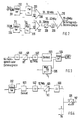
- Fig. 1 the left half shows the facilities available in the control center for a group of participants and the right half shows the facilities available at a participant in this group.
- the control center shown as a house, bears the reference symbol 100
- the facilities available to a subscriber which are shown as being in a single house, bear the reference symbol 111 as a whole.
- An optical waveguide 112 leads from the control center 100 to the one Group belonging participants is common to a star coupler SK, and from there participant-individual optical fibers L1 to L k each lead to a participant in the group.
- Both the subscriber-specific signals from the center to the group of subscribers, in the so-called downward direction, and the subscriber-specific signals from the group of subscribers to the center, in the so-called upward direction, are transmitted via this optical waveguide 112, with the Transmission in the downward direction a first wavelength ⁇ 0, eg equal to 1300 nm, and for transmission in the upward direction a second wavelength ⁇ 1, eg equal to 800 nm, is used.
- the optical waveguide 112 and the optical waveguide L1 to L k are thus used in wavelength division multiplexing for the transmission of signals in both directions. Details will be explained later.
- the system is used for the transmission of message signals of any kind, i.e. analog signals or digital signals, narrowband or broadband, of signals for distribution services, e.g. Television, or dialogue services, e.g. Telephony or data transmission, with subscriber-specific signals typically being transmitted in both directions.
- message signals of any kind, i.e. analog signals or digital signals, narrowband or broadband, of signals for distribution services, e.g. Television, or dialogue services, e.g. Telephony or data transmission, with subscriber-specific signals typically being transmitted in both directions.
- the system can advantageously be used for handling the dialog services such as telephony and data transmission separately from the distribution services for use cases in which there is either no need for distribution services or these are only to be introduced later using a separate system.
- the invention is explained using the example of the transmission of subscriber-specific signals in both transmission directions (dialog services).
- the subscriber-specific signals are also called telephone and data signals, which means the following: analog signals from a conventional telephone set, digital signals at 64 kbit / s from a digital telephone set, digital signals at 144 kbit / s from an ISDN terminal and digital data signals from 2 to 34 Mbit / s.
- the telephone and data signals to be transmitted to the group of subscribers come from a local exchange 118, from which they are input into an adaptation circuit with modulation / demodulation devices 119, which, as will be explained later, preferably processes a frequency division multiplex signal from them.
- This multiplex signal is converted into an optical signal in an electrical-optical converter 120 by intensity-modulating its output light of the wavelength ⁇ 0.
- the optical signal is coupled by means of a coupler 125 into the optical waveguide 112 and transmitted via this in the vicinity of the participants to the star coupler SK, distributed there to the optical waveguides L 1 to L k and transmitted via this to the participants.
- the optical fiber designated L3 is connected to the subscriber 111.
- the received optical signal is decoupled with a coupler 125, input into an optical-electrical converter 121 and converted into an electrical signal by the latter.
- the demodulator of a modem 123 takes the desired signal from the frequency division multiplex signal containing the telephone and data signals and converts it into the suitable and standardized form suitable for the respective terminal, telephone or data terminal or ISDN subscriber device. He ensures that only the telephone or data signals intended for the terminals of subscriber 111 can reach these terminals. In the simplest case, the subscriber has only a single terminal, for example a telephone set 127. If he has several terminals and therefore several signals must be taken from the frequency division multiplex signal, there are a corresponding number of modems.
- a participant with multiple devices is understood to mean both a single participant and a community of participants whose members have their living or business premises in an apartment building.
- the devices 121 and 123 are installed at a central location (e.g. basement) within the (single or multi-family) house and to connect the end devices to them via the existing house wiring.
- the modulator of the modem 123 modulates the telephone or data signals to be sent from a terminal of the subscriber to the central office on a carrier with a subscriber-specific frequency. If the subscriber (or community of subscribers) has multiple terminals, e.g. has several telephones, several modems modulate different carriers, and a multiplexer, not shown, combines these signals into a frequency band. Either a single modulated carrier or a frequency band consisting of a plurality of modulated carriers is then converted in an electrical-optical converter 122 into an optical signal which is present in the individual optical fibers, e.g. L3, is coupled by means of a coupler 126.
- the participants belonging to a group use an individual carrier frequency for each terminal belonging to a participant in the group. For example, there are 64 such carrier frequencies are provided. Instead of 64, another number, generally called m, of carrier frequencies can also be provided.
- the entirety of the subscribers grouped into a group of subscribers can thus operate up to m terminals for telephony or data transmission.
- the distribution among the individual participants is based on their individual communication needs and the available bandwidth in the system.
- the electrical-optical converters 122 present at the different participants all work with approximately the same operating wavelength ⁇ 1, so that in the star coupler SK e.g. 64 optical signals are irradiated with approximately the same operating wavelength ⁇ 1, which differ by the frequency (frequencies) of the carrier (carrier mixture) modulating the respective electrical-optical converter 127.
- an optical-to-electrical converter 129 which converts the received mixture of optical signals with the same wavelength, which the coupler 125 couples out of the optical waveguide 112, into a mixture of electrical signals with different carrier frequencies, and converts this to the input of the modulation / demodulation device 119.
- the telephone or data signals are present in the same form and quality that is prescribed for the transmission of telephone or ISDN signals or data signals.
- the couplers 125 and 126 are wavelength selective and separate the two wavelengths ⁇ 0 and ⁇ 1 without great optical losses and with very little crosstalk.
- FIG. 2 shows the modulator / multiplex part of the device 119 for telephone and data signals shown in FIG. 1, which is located in the control center.
- the telephone signals coming in from the local exchange (118 in FIG. 1) via a normal two-wire line 201 are converted in a so-called adapter 202 into a form which is suitable for transmission by a four-wire system with frequency modulation.
- the adapter 202 essentially has the function of a converter, for example for two-wire-four-wire implementation, for dialing signals, wake-up signals, etc.
- the signal resulting from this implementation reaches the modulation input of a modulator 203 and is modulated there onto a carrier with the frequency f 1 by means of frequency modulation .
- This carrier frequency f1 is individually a telephone subscriber line one of the participants in the assigned to the group of participants explained with reference to FIG. 1.
- the subscribers in this group can also use other connections, e.g. Connections to a digital network, e.g. to ISDN (Integrated Service Digital Network).
- a digital network e.g. to ISDN (Integrated Service Digital Network).
- the digital ISDN signals reach an adapter 211 for ISDN signals, and its output digital signal to the modulation input of a modulator 205 suitable for digital signals, in which it is e.g. by phase shift keying (English: phase shift keying, PSK) or frequency shift keying (eng .: frequency shift keying, FSK) a carrier with an individually assigned to this ISDN subscriber frequency f32 is modulated.
- phase shift keying English: phase shift keying, PSK
- frequency shift keying eng .: frequency shift keying, FSK
- the modulation of a carrier with the frequency f 1 by frequency modulation with telephone signals and in the second group the modulation of a carrier with the frequency f 3 by phase shift keying with ISDN signals is shown by the one group. Any mixes are possible.
- a first power adder 206 holds 32 modulated carriers with the different ones Carrier frequencies f1 to f32 to a frequency band with a bandwidth of 20 to 30 MHz
- a second power adder 207 also summarizes a group of 32 modulated carriers with the frequencies f1 to f32 to a frequency band with the same bandwidth 20 to 30 MHz.
- One of these two frequency bands is converted into the frequency band 30 to 40 MHz by means of a converter 208 and a downstream filter 209, and these two frequency bands are combined in a power adder 210 to form a frequency band of 20 to 40 MHz which contains up to 64 telephone and data signals may contain.
- This frequency band is the output signal of the device 119 shown in FIG. 1.
- a transmission of a large number of signals by frequency modulation of different carriers and by intensity modulation of a single optical transmitter by the signal mixture is known from "Electronics Letters", 22nd October 1987, VOL. 23, No. 22, pp. 1196 to 1197.
- the signals there are television signals and a transmission of telephone or ISDN signals (dialog services) is not mentioned.
- the frequency band from 20 to 40 MHz containing these signals is pre-filtered in a pre-filter 500, which is tuned to the frequency individually assigned to the subscriber connection under consideration, and the desired carrier is thereby separated from the mixture of modulated carriers, but this is done only incompletely, that is to say other carriers are still included in the output signal, though with lower amplitude.
- this signal is mixed with an auxiliary carrier HT, the frequency of which is selected such that the desired carrier is converted to an intermediate frequency of preferably 10.7 MHz which is uniform for all carriers.
- a downstream intermediate frequency filter 502 which is tuned to this intermediate frequency, practically isolates the useful information converted to this frequency from the other interfering carriers.
- An FM demodulator is used as the demodulator 503, if it is a telephone connection, and a PSK or FSK demodulator is used if it is an ISDN connection.
- the conversion to the intermediate frequency 10.7 MHz, subsequent filtering and FM demodulation corresponds to the signal processing in today's FM radio receivers and therefore has the advantage that cost-effective and proven circuits can be used. Another advantage is that uniform demodulators, uniform intermediate frequency filters and, apart from the frequency of the subcarrier, uniform intermediate frequency converters can be used for all subscriber connections.
- the telephone or ISDN signal appearing at the output of the demodulator 503 is finally implemented in an adapter 504, the function of which has already been explained in connection with FIG. 2, in such a way that it is suitable for the subscriber equipment (telephone set or ISDN device) standard-compliant signal is restored.
- the signals to be sent from this subscriber device to the control center are implemented by the adapter 504 and a modulator 505 connected downstream thereof, which is an FM modulator for an analog telephone signal and a phase shift keying or frequency shift keying modulator for a data signal, so that a modulated carrier is included one of the subscriber devices within a group of subscribers individually assigned frequency f 1 arises.
- this modulated carrier is then passed directly to the electrical-optical converter 122 of the subscriber shown in FIG. 1 or, if the subscriber has several terminals, via a multiplexer, not shown, so that in the latter case the converter 122 is known to be known existing light is modulated in its light intensity by a signal mixture of several modulated carriers.
- the modulators and demodulators shown in FIGS. 2 and 3 can be switchable so that they can either process telephone signals by frequency modulation or data signals by frequency or phase shift keying modulation.
- FIG. 4 shows the demodulator part of the device 119 from FIG. 1.
- an optical star coupler is shown as optical means for distributing the optical signal transmitted in the downward direction and for coupling the signals to be transmitted in the upward direction from the subscribers to the center into the optical waveguide 112.
- optical means can also be provided with distributed optical couplers, as is known per se from DE-A1-35 07 064, FIG. 1 mentioned at the beginning.
- optical means do not have to be passive, but can e.g. optical amplifiers or electrical amplifiers with associated optical-electrical and electrical-optical converters can be inserted.
- a supplement relates to the choice of frequencies for the transmission of the telephone or data signals, both in the downward and in the upward direction.
- the various signals explained above can be used as telephone or data signals.
- the carriers for the transmission of these signals e.g. lie in the frequency band from 20 MHz to 40 MHz.
- the carrier frequencies used for the transmission of the analog telephone signals and the digital signals with bit repetition frequencies from 64 to 144 kbit / s expediently have a uniform channel grid, i.e. a neighboring distance of the carrier frequencies, of 300 kHz. In this way, tried and tested circuits from VHF radio technology can be used to transmit the analog signals by means of frequency modulation.
- the carrier frequencies for the transmission of the digital data at 2 Mbit / s are expediently placed in the upper range of the frequency band from 20 MHz to 40 MHz, e.g. a carrier frequency for the transmission of such data at 38 MHz, the modulation for the transmission of the 2 Mbit / s digital signal requiring a bandwidth of approximately 1 to 2 MHz and thus a distance from adjacent carrier frequencies of 1 to 2 MHz.
- Another modification relates to the transmission of the frequency band containing a large number of modulated carriers as an optical signal.
- a single electrical-optical converter 120 receives, as an input signal, a frequency division multiplex signal which contains a multiplicity of modulated carriers.
- the problem with this type of transmission is the noise of the system, i.e. in the case of many carriers to be transmitted simultaneously via an optical transmitter, the signal-to-noise ratio in each of the individual channels can become insufficient.
- the fact that the mixture of signals from the many carriers allows only a very small degree of modulation per carrier of the laser used in the electrical-optical converter, so that the laser is not overdriven. If you increase the degree of modulation in the laser, the input signal comes to excessive peak values that overdrive the laser. Interferences between the useful signals then form interference products which can greatly reduce the quality of the useful signals.
- the total frequency band to be transmitted is divided into a plurality of subbands, each of which contains only part of the total of the modulated carriers to be transmitted, each subband in its own electrical-optical converter into an optical one Implement signal, using a uniform wavelength for all optical signals, and to couple these optical signals into the optical waveguide 112 (FIG. 1) running between the center and the group of subscribers.
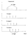
- a frequency band with a plurality of carriers is subdivided into n subbands such that a group of m carriers is contained in one of the subbands, and thus a total of the plurality m x n carriers of the originally present frequency band as shown in FIG. 5 on the different subbands is divided.
- the subbands can therefore each have the entire spectrum of the original transmission band. However, they contain a significantly smaller number of carriers than the original frequency band.
- each of the n subbands is given its own electrical-optical converter W1 to W n and that their output signals are combined by means of a star coupler SK1 to form an optical sum signal and in the optical waveguide 112 (leading to the group of participants) Fig. 1) are coupled.
- Each electrical-optical converter more precisely the laser it contains, can now be optimally controlled with regard to intermodulation distortion on the one hand and noise on the other. Because of the smaller number of carriers, the degree of modulation per carrier in the laser is significantly higher, so that the signal-to-noise ratio is significantly better for each carrier signal.
- the wavelength of the transducers W 1 to W n is preferably chosen as a uniform wavelength, for example approximately 1300 nm.
- the transmitted optical sum signal is converted into an electrical signal with a single optical receiver 121, as shown in FIG. 1, which contains all the original carriers, but with a far better signal quality than when transmitted with only one optical transmitter.
- the parallel use of a plurality of lasers described above has the further advantage of a higher light level at the output of the star coupler SK, which facilitates bridging a larger optical path loss or the distribution of the optical signals by means of optical star couplers to a number of subscribers.
- a supplement is described below that affects the safety of system users in the event of a fiber break. Because in the system preferably lasers are used as optical transmission elements, there is a need to switch off the lasers at the ends of the transmission path in the event of certain faults, for example when an excavator tears an optical fiber cable, in order to avoid the risk of eye accidents and the consequential damage associated therewith.
- optical transmission system it may be necessary to work with a high optical transmission power (more than -6 dBm) in order to achieve certain system properties, such as e.g. bridging a minimum distance between the control center and the participants or maintaining a certain signal-to-noise ratio.
- a return channel to send an alarm signal from the subscriber side to the transmitting center in order to switch off the laser there is not sufficient, since it is not possible to send back an alarm signal if the cable is defective, since each subscriber has only one cable or one single optical fiber is connected to the control center.
- one of the protective devices to be described below can therefore be present.
- FIG. 7 shows a protective device which provides an optical or electrical loop for monitoring an optical waveguide path. If a fiber break on an optical fiber link between two points A and B, for example, as shown in FIG. 7, is to be monitored between the control center 100 and the coupler SK, this is done with an optical or electrical loop 181, which runs in the immediate vicinity of the optical fiber line to be monitored. For example, a copper wire runs from a monitoring device 180 along the optical waveguide 112 to the coupler 113 and from there back to the monitoring device. The monitoring device sends a current via this loop, which flows continuously in the undisturbed operating state. If the cable is torn, the loop is also broken, so that the monitoring device causes the laser in the electrical-optical converter 120 to be switched off.
- an optical or electrical loop 181 which runs in the immediate vicinity of the optical fiber line to be monitored.
- a copper wire runs from a monitoring device 180 along the optical waveguide 112 to the coupler 113 and from there back to the monitoring device.
- the monitoring device sends a
- the copper wires can either be embedded in the accessory pack of the optical cable, or a thin copper cable can be laid parallel to the optical fiber cable.
- optical waveguides can also be used, which are part of the optical cable containing the transmission optical waveguide. In this case they are spliced together near the coupler and a fiber break is determined by the fact that the light path is interrupted via this optical loop from the center to the coupler and back.
- FIG. 8 shows a protective device in which an optical coupler 184 is spliced in between the electrical-optical converter 120 for the signal to be transmitted and the fiber cable, and the optical signal to be transmitted is coupled into the transmission optical fiber 112 via this coupler .
- the optical signals reflected and backscattered from this are detected at one end of the coupler 184 with an optical-electrical converter 182.
- a monitoring circuit 183 evaluating the electrical output signal of the converter 182 causes the laser contained in the electrical-optical converter 120 to be switched off when the detected light exceeds a predetermined threshold value. This is based on the fact that an excessively high level of the reflected light indicates a break in the optical waveguide.
- the protective device According to a development of the protective device according to FIG. 8, it is also possible to provide an optical-electrical converter at the still free end of the coupler 184. This then detects a portion of the light emitted by the electrical-optical converter and provides an electrical output signal that can be used on the one hand for electrical negative feedback of the laser in order to linearize the laser characteristic curve and whose low-frequency component can be used to set the operating point of the laser.
- the protective devices described above can not only be used in connection with the system according to the invention but can also be regarded as independent solutions when it comes to monitoring an optical transmission path between two points A and B with regard to a line interruption.
- the signals can also be transmitted in time division multiplex or in code division multiplex.
- the signals to be transmitted to a group of participants are converted into a digital time-division multiplex signal with a bit repetition frequency of e.g. about 8 Mbit / s combined, and this is transmitted, where appropriate it is also modulated onto a carrier and / or is limited to a suitable frequency band by coding with a line code.
- Analog telephone signals are converted into digital signals before time division multiplexing. Each participant has demultiplexing devices that extract the signals intended for him.
- the code division multiplex method is used to transmit the telephone and data signals from the center to the subscribers, the digital (or digitized) signals for a group are each multiplied by an address code and combined in a power adder to form a code division multiplex signal mixture, and this being transferred.
- Each participant has demultiplexing devices that take the signal intended for him.
- Time division multiplexing or code division multiplexing can also be used to transmit the telephone and data signals in the opposite direction.
- the multiplexers present at the subscribers then ensure that the telephone or data signals to be sent from a group of subscribers to the central station are converted into an optical signal with the wavelength ⁇ 1 in time segments of a (time-division multiplex) pulse frame or individually assigned address codes will.
- a mixture of optical signals is then transmitted to the control center, which are not determined by their wavelengths, but by the periods in which they contain their telephone or data signal, or by the codes of the respective electrical-optical converter 122 (FIG. 1 ) distinguish between the modulating digital signal (or the digital signals).
- the control center contains the suitable demultiplexing devices in order to resolve the electrical output signal of the optical-electrical converter 129 (FIG. 1) into its individual signals.
- the combination is preferably used that the transmission in the downward direction takes place in time division multiplexing and the transmission in the upward direction takes place in code division multiplexing.
Abstract
Description
Die Erfindung betrifft ein System nach dem Oberbegriff des Patentanspruchs 1. Ein Solches System ist bekannt aus DE-A1-35 07 064, Fig 2. Bei dem dort gezeigten System werden die von der Zentrale zu einer Gruppe von Teilnehmern zu übertragenden Signale als digitale Signale übertragen, und das elektrische Multiplexsignal, zu dem sie in der Zentrale zusammengefaßt werden, ist ein Zeitmultiplex-Signal. In der entgegengesetzten Richtung, nämlich von der Gruppe von Teilnehmern zu der Zentrale werden die Signale dadurch übertragen, daß sie mit teilnehmerindividuellen Wellenlängen über die teilnehmerindividuellen Lichtwellenleiter zum gemeinsamen Lichtwellenleiter und von dort über diesen zur Zentrale übertragen werden. Für die verschiedenen Richtungen werden verschiedene Wellenlängen verwendet, so daß dieselben Lichtwellenleiter, die für die Übertragung in eine Richtung verwendet werden, auch für die Übertragung in die entgegengesetzte Richtung verwendet werden und die Richtungstrennung im Wellenlangenmultiplex erfolgt.The invention relates to a system according to the preamble of
Die bei dem bekannten System in der Zentrale und bei den Teilnehmern vorhandenen Multiplex- bzw. Demultiplexeinrichtungen zur Bildung bzw. Auflösung des Zeitmultiplexsignals erfordern einen beträchtlichen Schaltungsaufwand, was einer kostengünstigen Realisierung des bekannten Systems im Wege steht.The existing multiplexing or demultiplexing devices in the known system in the center and in the subscribers for the formation or resolution of the time-division multiplexing signal require a considerable amount of circuitry, which stands in the way of an inexpensive implementation of the known system.
Es ist daher die Aufgabe der Erfindung, ein anderes, billigeres System der eingangs genannten Art anzugeben.It is therefore the object of the invention to provide another, cheaper system of the type mentioned at the outset.
Die Aufgabe wird wie im Patentanspruch 1 angegeben gelöst. Weiterbildungen ergeben sich aus den Unteransprüchen.The object is achieved as indicated in
Die Erfindung wird nun anhand der Zeichnungen beispielsweise naher erläutert.The invention will now be explained in more detail with reference to the drawings, for example.
Es zeigen:
- Fig. 1 den Grundaufbau des erfindungsgemäßen Systems,
- Fig. 2 eine Modulations- und Multiplexeinrichtung zur Aufbereitung des die von der Zentrale zu der Gruppe von Teilnehmern zu übertragenden Fernsprech- und Datensignale enthaltenden Frequenzmultiplexsignals,
- Fig. 3 eine teilnehmerseitige Demodulationseinrichtung und Modulationseinrichtung für Fernsprech- und Datensignale,
- Fig. 4 eine in der Zentrale pro Teilnehmer vorhandene Demodulationseinrichtung für Fernsprech- und Datensignale,
- Fig. 5 eine schematische Aufteilung des Frequenzmultiplexsignals in Teilbänder,
- Fig. 6 eine Anordnung mehrerer Elektrisch-optisch-Wandler zur Umwandlung der elektrischen Teilbänder in optische Signale,
- Fig. 7 eine erste Schutzvorrichtung zur Feststellung einer Unterbrechung der Lichtwellenleiter-Strecke und
- Fig. 8 eine zweite, alternative Schutzvorrichtung zur Feststellung einer Unterbrechung der Lichtwellenleiter-Strecke.
- 1 shows the basic structure of the system according to the invention,
- 2 shows a modulation and multiplexing device for processing the frequency multiplex signal containing the telephone and data signals to be transmitted from the central office to the group of subscribers,
- 3 shows a subscriber-side demodulation device and modulation device for telephone and data signals,
- 4 shows a demodulation device for telephone and data signals in the center for each subscriber,
- 5 shows a schematic division of the frequency division multiplex signal into subbands,
- 6 shows an arrangement of a plurality of electrical-optical converters for converting the electrical subbands into optical signals,
- Fig. 7 shows a first protective device for detecting an interruption in the optical fiber path and
- Fig. 8 shows a second, alternative protective device for detecting an interruption in the optical fiber path.
In Fig. 1 zeigt die linke Hälfte die in der Zentrale für eine Gruppe von Teilnehmern vorhandenen Einrichtungen und die rechte Hälfte die bei einem Teilnehmer dieser Gruppe vorhandenen Einrichtungen. Die Zentrale, als Haus dargestellt, trägt das Bezugszeichen 100, und die bei einem Teilnehmer vorhandenen Einrichtungen, die als in einem einzigen Haus befindlich dargestellt sind, tragen als Gesamtheit das Bezugszeichen 111. Von der Zentrale 100 führt ein Lichtwellenleiter 112, der den zu einer Gruppe gehörenden Teilnehmern gemeinsam ist, zu einem Sternkoppler SK, und von dort führen teilnehmerindividuelle Lichtwellenleiter L₁ bis Lk jeweils zu einem Teilnehmer der Gruppe.In Fig. 1, the left half shows the facilities available in the control center for a group of participants and the right half shows the facilities available at a participant in this group. The control center, shown as a house, bears the
Über diesen Lichtwellenleiter 112 werden sowohl die teilnehmerindividuellen Signale von der Zentrale zur Gruppe von Teilnehmern, in der sogenannten Abwärtsrichtung, als auch die teilnehmerindividuellen Signale von der Gruppe von Teilnehmern zur Zentrale, in der sogenannten Aufwärtsrichtung, übertragen, wobei zur Übertragung in Abwärtsrichtung eine erste Wellenlänge λ₀, z.B. gleich 1300 nm, und zur Übertragung in Aufwärtsrichtung eine zweite Wellenlänge λ₁, z.B. gleich 800 nm, verwendet wird. Der Lichtwellenleiter 112 und die Lichtwellenleiter L₁ bis Lk werden also im Wellenlangenmultiplex zur Übertragung von Signalen in beiden Richtungen verwendet. Einzelheiten werden an späterer Stelle erläutert.Both the subscriber-specific signals from the center to the group of subscribers, in the so-called downward direction, and the subscriber-specific signals from the group of subscribers to the center, in the so-called upward direction, are transmitted via this
Das System dient zur Übertragung von Nachrichtensignalen beliebiger Art, also von Analogsignalen oder Digitalsignalen, schmalbandig oder breitbandig, von Signalen für Verteildienste, z.B. Fernsehen, oder von Dialogdiensten, z.B. Fernsprechen oder Datenübertragung, wobei typischerweise teilnehmerindividuelle Signale in beiden Richtungen zu übertragen sind.The system is used for the transmission of message signals of any kind, i.e. analog signals or digital signals, narrowband or broadband, of signals for distribution services, e.g. Television, or dialogue services, e.g. Telephony or data transmission, with subscriber-specific signals typically being transmitted in both directions.
Das System ist vorteilhaft einsetzbar zur Abwicklung der Dialogdienste wie Fernsprechen und Datenübertragung separat von den Verteildiensten für Anwendungsfälle, in denen entweder kein Bedarf nach Verteildiensten besteht oder diese erst später unter Verwendung eines separaten Systems eingeführt werden sollen.The system can advantageously be used for handling the dialog services such as telephony and data transmission separately from the distribution services for use cases in which there is either no need for distribution services or these are only to be introduced later using a separate system.
Die Erfindung wird am Beispiel der Übertragung von teilnehmerindividuellen Signalen in beiden Übertragungsrichtungen (Dialogdienste) erlautert. Die teilnehmerindividuellen Signale werden dabei auch Fernsprech- und Datensignale genannt, wobei hierunter folgendes zu verstehen ist: Analogsignale eines herkömmlichen Fernsprechapparates, Digitalsignale mit 64 kbit/s eines digitalen Fernsprechapparates, Digitalsignale mit 144 kbit/s eines ISDN-Endgerätes und digitale Datensignale mit 2 bis 34 Mbit/s.The invention is explained using the example of the transmission of subscriber-specific signals in both transmission directions (dialog services). The subscriber-specific signals are also called telephone and data signals, which means the following: analog signals from a conventional telephone set, digital signals at 64 kbit / s from a digital telephone set, digital signals at 144 kbit / s from an ISDN terminal and digital data signals from 2 to 34 Mbit / s.
Die zu der Gruppe von Teilnehmern zu übertragenden Fernsprech- und Datensignale stammen von einer Ortsvermittlungsstelle 118, von der sie in eine Anpassungsschaltung mit Modulations-/Demodulationseinrichtungen 119 eingegeben werden, die, wie an späterer Stelle erläutert wird, aus ihnen vorzugsweise ein Frequenzmultiplexsignal aufbereitet. Dieses Multiplexsignal wird in einem Elektrisch-optisch-Wandler 120 in ein optisches Signal umgesetzt, indem es dessen Ausgangslicht der Wellenlänge λ₀ intensitätsmoduliert. Das optische Signal wird mittels eines Kopplers 125 in den Lichtwellenleiter 112 eingekoppelt und über diesen in die Nähe der Teilnehmer zum Sternkoppler SK übertragen, dort auf die Lichtwellenleiter L₁ bis Lk verteilt und über diese bis zu den Teilnehmern übertragen. In der Zeichnung ist der mit L₃ bezeichnete Lichtwellenleiter mit dem Teilnehmer 111 verbunden.The telephone and data signals to be transmitted to the group of subscribers come from a
Beim Teilnehmer wird das empfangene optische Signal mit einem Koppler 125 ausgekoppelt, in einen Optisch-elektrisch-Wandler 121 eingegeben und von diesem in ein elektrisches Signal umgesetzt.At the subscriber, the received optical signal is decoupled with a
Der Demodulator eines Modems 123 entnimmt dem die Fernsprech- und Datensignale enthaltenden Frequenzmultiplexsignal das gewünschte Signal und setzt es in die für das jeweilige Endgerät, Fernsprechapparat oder Datenendgerät oder ISDN-Teilnehmereinrichtung, geeignete und standardisierte Form um. Dabei sorgt er dafür, daß nur die für die Endgeräte des Teilnehmers 111 bestimmten Fernsprech- oder Datensignale zu diesen Endgeräten gelangen können. Im einfachsten Falle hat der Teilnehmer nur ein einziges Endgerät, z.B. einen Fernsprechapparat 127. Wenn er mehrere Endgeräte hat und daher mehrere Signale dem Frequenzmultiplexsignal entnommen werden müssen, sind entsprechend viele Modems vorhanden.The demodulator of a
Als Teilnehmer mit mehreren Endgeräten ist sowohl ein einzelner Teilnehmer als auch eine Teilnehmergemeinschaft, deren Mitglieder ihre Wohn- oder Geschäftsräume in einem Mehrfamilienhaus haben, zu verstehen.A participant with multiple devices is understood to mean both a single participant and a community of participants whose members have their living or business premises in an apartment building.
Falls mehrere Endgeräte vorhanden sind, ist es in jedem Falle zweckmäßig, die Einrichtungen 121 und 123 an zentraler Stelle (z.B. Keller) innerhalb des (Ein- oder Mehrfamilien-) Hauses zu installieren und die Endgeräte über die meistens schon vorhandene Hausverkabelung daran anzuschließen.If there are several end devices, it is advisable in any case to install the
Die von einem Endgerät des Teilnehmers zur Zentrale zu sendenden Fernsprech- oder Datensignale moduliert der Modulator des Modems 123 einem Träger mit einer teilnehmerindividuellen Frequenz auf. Falls der Teilnehmer (oder die Teilnehmergemeinschaft) mehrere Endgeräte, z.B. mehrere Fernsprechapparate hat, modulieren mehrere Modems verschiedene Träger, und ein nicht gezeigter Multiplexer faßt diese Signale zu einem Frequenzband zusammen. Entweder ein einziger modulierter Träger oder ein Frequenzband aus mehreren modulierten Trägern wird dann in einem Elektrisch-optisch-Wandler 122 in ein optisches Signal umgesetzt, das in den zum Sternkoppler SK führenden teilnehmerindividuell vorhandenen Lichtwellenleiter, z.B. L₃, mittels eines Kopplers 126 eingekoppelt wird.The modulator of the
Die zu einer Gruppe gehörenden Teilnehmer verwenden für jedes zu einem Teilnehmer der Gruppe gehörende Endgerät eine individuelle Trägerfrequenz. Es sind z.B. 64 solcher Trägerfrequenzen vorgesehen. Statt 64 kann aber auch eine andere Zahl, allgemein m genannt, von Trägerfrequenzen vorgesehen sein. Die Gesamtheit der zu einer Gruppe von Teilnehmern zusammengefaßten Teilnehmer kann also bis zu m Endgeräte für Fernsprechen oder Datenübertragung betreiben. Die Aufteilung auf die einzelnen Teilnehmer richtet sich nach deren individuellen Kommunikationsbedürfnissen und der verfügbaren Bandbreite im System.The participants belonging to a group use an individual carrier frequency for each terminal belonging to a participant in the group. For example, there are 64 such carrier frequencies are provided. Instead of 64, another number, generally called m, of carrier frequencies can also be provided. The entirety of the subscribers grouped into a group of subscribers can thus operate up to m terminals for telephony or data transmission. The distribution among the individual participants is based on their individual communication needs and the available bandwidth in the system.
Die bei den verschiedenen Teilnehmern vorhandenen Elektrisch-optisch-Wandler 122 arbeiten alle etwa mit derselben Betriebswellenlänge λ1, so daß in den Sternkoppler SK z.B. 64 optische Signale mit etwa derselben Betriebswellenlänge λ1 eingestrahlt werden, die sich durch die Frequenz (Frequenzen) des den jeweiligen Elektrisch-optisch-Wandler 127 modulierenden Trägers (Trägergemisches) unterscheiden.The electrical-
Dieses Prinzip der Übertragung verschiedener Signale über einen einzigen Lichtwellenleiter ist für sich bekannt aus der DE-A 32 39 593.This principle of transmitting various signals via a single optical waveguide is known per se from DE-A 32 39 593.
In der Zentrale 100 befindet sich ein Optisch-elektrisch-Wandler 129, der das empfangene Gemisch aus optischen Signalen mit derselben Wellenlänge, das der Koppler 125 aus dem Lichtwellenleiter 112 auskoppelt, in ein Gemisch aus elektrischen Signalen mit unterschiedlichen Trägerfrequenzen umsetzt und dieses auf den Eingang der Modulations-/Demodulationseinrichtung 119 gibt. Diese trennt das elektrische Signalgemisch in die einzelnen Signale auf, demoduliert diese und stellt sie an seinen Ausgängen, z.B. 64 Ausgängen, als der Norm entsprechende Fernsprech- oder Datensignale als Eingangssignale für die Ortsvermittlungsstelle 118 zur Verfügung. An den Eingängen dieser Ortsvermittlungsstelle 118 liegen die Fernsprech- oder Datensignale in derselben Form und Qualität vor, die für die Übertragung von Fernsprechoder ISDN-Signalen oder Datensignalen vorgeschrieben ist.Located in the
Die Koppler 125 und 126 sind wellenlängenselektiv und trennen die beiden Wellenlängen λ₀ und λ₁ ohne große optische Verluste und mit sehr geringem Nebensprechen.The
Anhand der Fig. 2 wird nun beschrieben, welche Art der Modulation und Multiplexbildung die Modulations- und Multiplexeinrichtung der Einrichtung 119 durchführt.The type of modulation and multiplexing which the modulation and multiplexing device of the
In Fig. 2 ist der Modulator/Multiplex-Teil der in Fig. 1 gezeigten Einrichtung 119 für Fernsprech- und Datensignale, die sich in der Zentrale befindet, dargestellt.FIG. 2 shows the modulator / multiplex part of the
Die von der Ortsvermittlungsstelle (118 in Fig. 1) über eine normale Zweidraht-Leitung 201 eingehenden Fernsprechsignale werden in einem sogenannten Adapter 202 in eine Form umgesetzt, die zu einer Übertragung durch ein Vierdrahtsystem mit Frequenzmodulation geeignet ist. Der Adapter 202 hat im wesentlichen die Funktion eines Umsetzers, z.B. für Zweidraht-Vierdraht-Umsetzung, für Wählzeichen, Wecksignale usw. Das durch diese Umsetzung entstandene Signal gelangt auf den Modulationseingang eines Modulators 203 und wird dort einem Träger mit der Frequenz f₁ mittels Frequenzmodulation aufmoduliert. Diese Trägerfrequenz f₁ ist individuell einem Fernsprech-Teilnehmeranschluß eines der Teilnehmer der anhand von Fig. 1 erläuterten Gruppe von Teilnehmern zugeordnet.The telephone signals coming in from the local exchange (118 in FIG. 1) via a normal two-
Die Teilnehmer dieser Gruppe können, wie oben angedeutet, statt Fernsprechanschlüsse auch andere Anschlüsse, z.B. Anschlüsse an ein digitales Netz, z.B. an ISDN (Integrated Service Digital Network), haben. In diesem Falle gelangen die digitalen ISDN-Signale, wie dies für eine weitere Zweidraht-Leitung 204 gezeigt ist, auf einen Adapter 211 für ISDN-Signale, und dessen Ausgangs-Digitalsignal zum Modulationseingang eines für Digitalsignale geeigneten Modulators 205, in dem es z.B. durch Phasenumtastung (engl.: phase shift keying, PSK) oder Frequenzumtastung (eng.: frequency shift keying, FSK) einem Träger mit einer diesem ISDN-Teilnehmer individuell zugeordneten Frequenz f₃₂ aufmoduliert wird.As indicated above, the subscribers in this group can also use other connections, e.g. Connections to a digital network, e.g. to ISDN (Integrated Service Digital Network). In this case, the digital ISDN signals, as shown for a further two-
Bei dem eben gezeigten Beispiel entstehen auf diese Weise eine erste Gruppe von 32 Trägern mit verschiedenen Frequenzen aus dem Frequenzband von 20 bis 30 MHz, die entweder mit analogen Fernsprechsignalen frequenzmoduliert oder mit Digitalsignalen, z.B. ISDN-Signalen, durch Phasen- oder Frequenzumtastung moduliert sind. Im Beispiel ist von der einen Gruppe die Modulation eines Trägers mit der Frequenz f₁ durch Frequenzmodulation mit Fernsprechsignalen und bei der zweiten Gruppe die Modulation eines Trägers mit der Frequenz f₃₂ durch Phasenumtastmodulation mit ISDN-Signalen gezeigt. Beliebige Mischungen sind moglich.In the example just shown, this creates a first group of 32 carriers with different frequencies from the frequency band from 20 to 30 MHz, which either frequency-modulate with analog telephone signals or with digital signals, e.g. ISDN signals are modulated by phase or frequency shift keying. In the example, the modulation of a carrier with the
Im gezeigten Beispiel faßt ein erster Leistungsaddierer 206 32 modulierte Träger mit den verschiedenen Trägerfrequenzen f₁ bis f₃₂ zu einem Frequenzband mit einer Bandbreite von 20 bis 30 MHz zusammen, und ein zweiter Leistungsaddierer 207 faßt ebenso eine Gruppe von 32 modulierten Trägern mit den Frequenzen f₁ bis f₃₂ zu einem Frequenzband mit der gleichen Bandbreite 20 bis 30 MHz zusammen. Eines dieser beiden Frequenzbänder wird mittels eines Umsetzers 208 und eines nachgeschalteten Filters 209 in das Frequenzband 30 bis 40 MHz umgesetzt, und diese beiden Frequenzbänder werden in einem Leistungsaddierer 210 zu einem Frequenzband von 20 bis 40 MHz zusammengefaßt, das bis zu 64 Fernsprech- und Datensignale enthalten kann. Dieses Frequenzband ist das Ausgangssignal der in Fig. 1 gezeigten Einrichtung 119.In the example shown, a
Eine Übertragung einer Vielzahl von Signalen durch Frequenzmodulation verschiedener Träger und durch Intensitätsmodulation eines einzigen optischen Senders durch das Signalgemisch ist bekannt aus "Electronics Letters", 22nd October 1987, VOL. 23, No. 22, S. 1196 bis 1197. Die Signale sind dort Fernsehsignale, und eine Übertragung von Fernsprech- oder ISDN-Signalen (Dialogdienste) ist nicht erwähnt.A transmission of a large number of signals by frequency modulation of different carriers and by intensity modulation of a single optical transmitter by the signal mixture is known from "Electronics Letters", 22nd October 1987, VOL. 23, No. 22, pp. 1196 to 1197. The signals there are television signals and a transmission of telephone or ISDN signals (dialog services) is not mentioned.
Anhand von Fig. 3 wird nun die beim Teilnehmer stattfindende Verarbeitung der Fernsprech- und Datensignale erläutert. Das diese Signale enthaltende Frequenzband von 20 bis 40 MHz wird in einem Vorfilter 500, das auf die dem betrachteten Teilnehmeranschluß individuell zugeordnete Frequenz abgestimmt ist, vorgefiltert und dadurch der gewünschte Träger aus dem Gemisch von modulierten Trägern herausgetrennt, was jedoch nur unvollständig geschieht, d.h. die anderen Träger sind im Ausgangssignal noch enthalten, wenn auch mit geringerer Amplitude. In einem Zwischenfrequenz-Umsetzer 501 wird dieses Signal mit einem Hilfsträger HT gemischt, dessen Frequenz so gewählt ist, daß der gewünschte Träger auf eine für alle Träger einheitliche Zwischenfrequenz von vorzugsweise 10,7 MHz umgesetzt wird. Ein nachgeschaltetes Zwischenfrequenz-Filter 502, das auf diese Zwischenfrequenz abgestimmt ist, isoliert praktisch die auf diese Frequenz umgesetzte Nutzinformation von den anderen störenden Trägern. Nach der Demodulation in einem Demodulator 503 liegt schließlich das Fernsprech- oder Datensignal im usprünglichen Basisband vor.The processing of the telephone and data signals taking place at the subscriber will now be explained with reference to FIG. 3. The frequency band from 20 to 40 MHz containing these signals is pre-filtered in a pre-filter 500, which is tuned to the frequency individually assigned to the subscriber connection under consideration, and the desired carrier is thereby separated from the mixture of modulated carriers, but this is done only incompletely, that is to say other carriers are still included in the output signal, though with lower amplitude. In an
Als Demodulator 503 wird, wenn es sich um einen Fernsprechanschluß handelt, ein FM-Demodulator, und wenn es sich um einen ISDN-Anschluß handelt, ein PSK- oder FSK-Demodulator verwendet.An FM demodulator is used as the
Die Umsetzung auf die Zwischenfrequenz 10,7 MHz, anschließende Filterung und FM-Demodulation entspricht der Signalverarbeitung in heutzutage üblichen UKW-Rundfunkempfängern und hat daher den Vorteil, daß kostengünstige und erprobte Schaltungen eingesetzt werden können. Ein weiterer Vorteil liegt darin, daß für alle Teilnehmeranschlüsse einheitliche Demodulatoren, einheitliche Zwischenfrequenzfilter und, abgesehen von der Frequenz des Hilfsträgers, einheitliche Zwischenfrequenz-Umsetzer verwendbar sind.The conversion to the intermediate frequency 10.7 MHz, subsequent filtering and FM demodulation corresponds to the signal processing in today's FM radio receivers and therefore has the advantage that cost-effective and proven circuits can be used. Another advantage is that uniform demodulators, uniform intermediate frequency filters and, apart from the frequency of the subcarrier, uniform intermediate frequency converters can be used for all subscriber connections.
Das am Ausgang des Demodulators 503 erscheinende Fernsprech- oder ISDN-Signal wird schließlich in einem Adapter 504, dessen Funktion bereits im Zusammenhang mit Fig. 2 erläutert wurde, so umgesetzt, daß das für die Teilnehmereinrichtung (Fernsprechapparat oder ISDN-Einrichtung) normgerechte Signal wieder hergestellt wird.The telephone or ISDN signal appearing at the output of the
Die von dieser Teilnehmereinrichtung zur Zentrale zu sendenden Signale setzt der Adapter 504 und ein diesem nachgeschalteter Modulator 505, der für ein analoges Fernsprechsignal ein FM-Modulator und für ein Datensignal ein Phasenumtast- oder Frequenzumtast-Modulator ist, so um, daß ein modulierter Träger mit einer der Teilnehmereinrichtung innerhalb einer Gruppe von Teilnehmern individuell zugeordneten Frequenz f₁ entsteht. Dieser modulierte Träger wird dann im einfachsten Falle direkt auf den in Fig. 1 gezeigten Elektrisch-optisch-Wandler 122 des Teilnehmers gegeben oder, falls der Teilnehmer mehrere Endgeräte hat, über einen nicht gezeigten Multiplexer, so daß im letzteren Falle der im Wandler 122 bekanntlich vorhandene Laser durch ein Signalgemisch aus mehreren modulierten Trägern in seiner Lichtintensität moduliert wird.The signals to be sent from this subscriber device to the control center are implemented by the
Die in Fig. 2 und Fig. 3 gezeigten Modulatoren und Demodulatoren können umschaltbar sein, damit sie entweder Fernsprechsignale durch Frequenzmodulation oder Datensignale durch Frequenz- oder Phasenumtastmodulation verarbeiten können.The modulators and demodulators shown in FIGS. 2 and 3 can be switchable so that they can either process telephone signals by frequency modulation or data signals by frequency or phase shift keying modulation.
In Fig. 4 ist der Demodulator-Teil der Einrichtung 119 aus Fig. 1 gezeigt. Das über den in Fig. 1 gezeigten Lichtwellenleiter 112 empfangene optische Signal, das in dem Optisch-Elektrisch-Wandler 129 in ein elektrisches Signal umgesetzt wird, wird in dem zu beschreibenden Demodulator auf m (z.B. m = 64) Leitungen verteilt, da es bis zu m Fernsprech- oder Datensignale enthält.FIG. 4 shows the demodulator part of the
Dieses Signalgemisch gelangt auf verschiedene Demodulationswege, von denen ein einziger gezeigt ist. Dort erfolgt mit Hilfe eines Vorfilters 600, eines Zwischenfrequenz-Umsetzers 601, eines Zwischenfrequenz-Filters 602 und eines Demodulators 603 eine Demodulation, wie sie anhand der entsprechend bezeichneten Baugruppen im Zusammenhang mit Fig. 3 bereits erläutert ist. Das am Ausgang des Demodulators 603 erscheinende Fernsprech- oder Datensignal wird schließlich in einem Adapter 202, dessen Funktion bereits im Zusammenhang mit Fig. 2 erläutert wurde, so umgesetzt, daß es auf die zur Ortsvermittlungsstelle führende Zweidraht-Leitung gegeben werden kann.This mixture of signals travels to different demodulation paths, only one of which is shown. There, with the aid of a pre-filter 600, an intermediate frequency converter 601, an intermediate frequency filter 602 and a
Im vorstehend erläuterten Ausführungsbeispiel der Erfindung ist als optisches Mittel zum Verteilen des in Abwärtsrichtung übertragenen optischen Signals und zum Einkoppeln der in Aufwärtsrichtung von den Teilnehmern zur Zentrale zu sendenden Signale in den Lichtwellenleiter 112 ein optischer Sternkoppler gezeigt.In the exemplary embodiment of the invention explained above, an optical star coupler is shown as optical means for distributing the optical signal transmitted in the downward direction and for coupling the signals to be transmitted in the upward direction from the subscribers to the center into the
Selbstverständlich können als solche optischen Mittel auch verteilt angeordnete optische Koppler vorhanden sein, wie es aus der eingangs genannten DE-A1-35 07 064, Fig. 1, für sich bekannt ist.Of course, such optical means can also be provided with distributed optical couplers, as is known per se from DE-A1-35 07 064, FIG. 1 mentioned at the beginning.
Auch müssen die optischen Mittel nicht passiv sein, sondern es können an geeigneten Stellen z.B. optische Verstärker oder elektrische Verstärker mit zugehörigen Optisch-elektrisch- und Elektrisch-optisch-Wandlern eingefügt sein.Also, the optical means do not have to be passive, but can e.g. optical amplifiers or electrical amplifiers with associated optical-electrical and electrical-optical converters can be inserted.
Im folgenden werden noch einige Modifikationen und Ergänzungen des in Fig. 1 gezeigten Systems erläutert.Some modifications and additions to the system shown in FIG. 1 are explained below.
Eine Ergänzung bezieht sich auf die Wahl der Frequenzen für die Übertragung der Fernsprech- oder Datensignale, und zwar sowohl in der Abwärts-, als auch in der Aufwärtsrichtung. Als Fernsprech- oder Datensignale kommen die oben erläuterten verschiedenen Signale in Frage. Wie oben erwähnt, sollen die Träger zur Übertragung dieser Signale z.B. in dem Frequenzband von 20 MHz biS 40 MHz liegen. Die zur Übertragung der analogen Fernsprechsignale und der Digitalsignale mit Bitfolgefrequenzen von 64 bis 144 kbit/s verwendeten Trägerfrequenzen haben zweckmäßigerweise ein einheitliches Kanalraster, d.h. einen Nachbarabstand der Trägerfrequenzen, von 300 kHz. Hierdurch können zur Übertragung der Analogsignale durch die Frequenzmodulation erprobte Schaltungen aus der UKW-Rundfunktechnik verwendet werden. Die Trägerfrequenzen zur Übertragung der digitalen Daten mit 2Mbit/s werden zweckmäßigerweise in den oberen Bereich des Frequenzbandes von 20 MHz bis 40 MHz gelegt, z.B. eine Trägerfrequenz zur Übertragung solcher Daten bei 38 MHz, wobei die Modulation zur Übertragung des 2 Mbit/s-Digitalsignals eine Bandbreite von ca. 1 bis 2 MHz und damit einen Abstand zu benachbarten Trägerfrequenzen von 1 bis 2 MHz erfordert.A supplement relates to the choice of frequencies for the transmission of the telephone or data signals, both in the downward and in the upward direction. The various signals explained above can be used as telephone or data signals. As mentioned above, the carriers for the transmission of these signals e.g. lie in the frequency band from 20 MHz to 40 MHz. The carrier frequencies used for the transmission of the analog telephone signals and the digital signals with bit repetition frequencies from 64 to 144 kbit / s expediently have a uniform channel grid, i.e. a neighboring distance of the carrier frequencies, of 300 kHz. In this way, tried and tested circuits from VHF radio technology can be used to transmit the analog signals by means of frequency modulation. The carrier frequencies for the transmission of the digital data at 2 Mbit / s are expediently placed in the upper range of the frequency band from 20 MHz to 40 MHz, e.g. a carrier frequency for the transmission of such data at 38 MHz, the modulation for the transmission of the 2 Mbit / s digital signal requiring a bandwidth of approximately 1 to 2 MHz and thus a distance from adjacent carrier frequencies of 1 to 2 MHz.
Eine weitere Ergänzung betrifft die im System verwendeten Elektrisch-optisch-Wandler. Sind die Kennlinien dieser Wandler nicht hinreichend linear, so bilden sich Mischprodukte mit Frequenzen, die in das Übertragungsband fallen und dort sehr störend wirken können. Diese Störungen sind umso gravierender, je breiter das Frequenzspektrum des Eingangssignals ist. Um die Linearität der Elektrisch-optisch-Wandler zu verbessern, wird jeder dieser Wandler mit einer Schaltung zur Linearisierung ausgestattet, wobei die Linearisierung durch eine negative Rückkopplung des ausgesendeten optischen Signals etwa derart, wie sie z.B. aus der US-PS 3 996 526 bekannt ist, erfolgt.Another addition concerns the electrical-optical converters used in the system. If the characteristics of these converters are not sufficiently linear, mixed products are formed with frequencies that fall into the transmission band and can be very disruptive there. The broader the frequency spectrum of the input signal, the more serious these interferences. In order to improve the linearity of the electrical-optical converter, each of these converters is equipped with a Circuit for linearization equipped, the linearization is carried out by a negative feedback of the emitted optical signal approximately such as is known, for example, from US Pat. No. 3,996,526.
Eine weitere Modifikation betrifft die Übertragung des eine Vielzahl von modulierten Trägern enthaltenden Frequenzbandes als optisches Signal. Im oben erläuterten Ausführungsbeispiel der Einrichtung 119 (Fig. 1) ist vorgesehen, daß ein einziger Elektrisch-optisch-Wandler 120 als Eingangssignal ein Frequenzmultiplex-Signal erhält, das eine Vielzahl von modulierten Trägern enthält.Another modification relates to the transmission of the frequency band containing a large number of modulated carriers as an optical signal. In the exemplary embodiment of the device 119 (FIG. 1) explained above, it is provided that a single electrical-
Problematisch bei dieser Art der Übertragung ist das Rauschen des Systems, d.h. bei vielen gleichzeitig über einen optischen Sender zu übertragenden Trägern kann der Geräuschabstand in jedem der einzelnen Kanäle ungenügend werden. Das liegt u.a. daran, daß das Signalgemisch aus den vielen Trägern nur einen sehr kleinen Modulationsgrad pro Träger des im Elektrisch-optisch-Wandler verwendeten Lasers gestattet, damit der Laser nicht übersteuert wird. Erhöht man den Modulationsgrad beim Laser, so kommt das Eingangssignal auf zu hohe Spitzenwerte, die den Laser übersteuern. Interferenzen zwischen den Nutzsignalen bilden dann Störprodukte, die die Qualität der Nutzsignale stark herabsetzen können.The problem with this type of transmission is the noise of the system, i.e. in the case of many carriers to be transmitted simultaneously via an optical transmitter, the signal-to-noise ratio in each of the individual channels can become insufficient. Among other things, the fact that the mixture of signals from the many carriers allows only a very small degree of modulation per carrier of the laser used in the electrical-optical converter, so that the laser is not overdriven. If you increase the degree of modulation in the laser, the input signal comes to excessive peak values that overdrive the laser. Interferences between the useful signals then form interference products which can greatly reduce the quality of the useful signals.
Gemäß einer vorteilhaften Ausgestaltung der Erfindung ist daher vorgesehen, das insgesamt zu übertragende Frequenzband in mehrere Teilbänder, von denen jedes nur einen Teil der insgesamt zu übertragenden modulierten Träger enthält, aufzuteilen, jedes Teilband in einem eigenen Elektrisch-optisch-Wandler in ein optisches Signal umzusetzen, wobei für alle optischen Signale eine einheitliche Wellenlänge verwendet wird, und diese optischen Signale in den zwischen der Zentrale und der Gruppe von Teilnehmern verlaufenden Lichtwellenleiter 112 (Fig. 1) einzukoppeln.According to an advantageous embodiment of the invention, it is therefore provided that the total frequency band to be transmitted is divided into a plurality of subbands, each of which contains only part of the total of the modulated carriers to be transmitted, each subband in its own electrical-optical converter into an optical one Implement signal, using a uniform wavelength for all optical signals, and to couple these optical signals into the optical waveguide 112 (FIG. 1) running between the center and the group of subscribers.
In Fig. 5 ist gezeigt, wie das zu übertragende Frequenzband in die Teilbänder aufgeteilt wird. Ein Frequenzband mit einer Vielzahl von Trägern wird in n Teilbänder so unterteilt, daß jeweils eine Gruppe von m Trägern in einem der Teilbänder enthalten ist und dadurch insgesamt die Vielzahl m X n Träger des ursprünglich vorliegenden Frequenzbandes wie in Fig. 5 gezeigt auf die verschiedenen Teilbänder aufgeteilt ist. Die Teilbänder können also jeweils das ganze Spektrum des ursprünglichen Übertragungsbandes haben. Sie enthalten jedoch eine deutlich geringere Anzahl von Trägern als das ursprüngliche Frequenzband.5 shows how the frequency band to be transmitted is divided into the subbands. A frequency band with a plurality of carriers is subdivided into n subbands such that a group of m carriers is contained in one of the subbands, and thus a total of the plurality m x n carriers of the originally present frequency band as shown in FIG. 5 on the different subbands is divided. The subbands can therefore each have the entire spectrum of the original transmission band. However, they contain a significantly smaller number of carriers than the original frequency band.
In Fig. 6 ist gezeigt, daß jedes der n Teilbänder auf einen eigenen Elektrisch-optisch-Wandler W₁ bis Wn gegeben wird und daß deren Ausgangssignale mittels eines Sternkopplers SK1 zu einem optischen Summensignal zusammengefaßt und in den zur Gruppe von Teilnehmern führenden Lichtwellenleiter 112 (Fig. 1) eingekoppelt werden. Hierbei kann nun jeder Elektrisch-optisch-Wandler, genauer gesagt der in ihm enthaltene Laser, optimal im Hinblick auf Intermodulationsverzerrungen einerseits und Rauschen andererseits ausgesteuert werden. Dabei liegt wegen der geringeren Anzahl der Träger der Modulationsgrad je Träger im Laser deutlich höher, so daß für jedes Trägersignal der Geräuschabstand deutlich besser ist.In Fig. 6 it is shown that each of the n subbands is given its own electrical-optical converter W₁ to W n and that their output signals are combined by means of a star coupler SK1 to form an optical sum signal and in the optical waveguide 112 (leading to the group of participants) Fig. 1) are coupled. Each electrical-optical converter, more precisely the laser it contains, can now be optimally controlled with regard to intermodulation distortion on the one hand and noise on the other. Because of the smaller number of carriers, the degree of modulation per carrier in the laser is significantly higher, so that the signal-to-noise ratio is significantly better for each carrier signal.
Die Wellenlänge der Wandler W₁ bis Wn wird vorzugsweise als eine einheitliche Wellenlänge, z.B. ca. 1300 nm gewählt. Empfangsseitig wird das übertragene optische Summensignal wie in Fig. 1 gezeigt mit einem einzigen optischen Empfänger 121 in ein elektrisches Signal umgesetzt, das alle ursprünglichen Träger enthält, jedoch mit einer weit besseren Signalqualität als bei der Übertragung mit nur einem optischen Sender.The wavelength of the
Zu diesem Übertragungsverfahren ist zu bemerken, daß die Aufteilung eines breitbandigen Frequenzmultiplex-Signals in Teilbänder und die getrennte Umsetzung der Teilbänder in optische Signale bekannt ist aus der DE-A1 32 03 785. Dort werden allerdings optische Signale mit verschiedenen Wellenlängen erzeugt und über einen einzigen Lichtwellenleiter übertragen. Andererseits ist es aus der DE-A1 32 39 593 bekannt, mehrere nicht überlappende Frequenzbänder mit jeweils einem Elektrisch-optisch Wandler in optische Signale mit einer einheitlichen Wellenlänge umzusetzen, diese mit einem Sternkoppler zusammenzufassen und über einen einzigen Lichtwellenleiter zu übertragen.Regarding this transmission method, it should be noted that the division of a broadband frequency division multiplex signal into subbands and the separate conversion of the subbands into optical signals is known from DE-A1 32 03 785. There, however, optical signals with different wavelengths are generated and over a single one Optical fiber transmission. On the other hand, it is known from DE-A1 32 39 593 to convert several non-overlapping frequency bands, each with an electrical-optical converter, into optical signals with a uniform wavelength, to combine them with a star coupler and to transmit them via a single optical waveguide.
Die vorstehend beschriebene parallele Verwendung mehrerer Laser hat als weiteren Vorteil einen höheren Lichtpegel am Ausgang des Sternkopplers SK zur Folge, was die Überbrückung einer größeren optischen Streckendämpfung oder die Verteilung der optischen Signale mittels optischer Sternkoppler auf mehrere Teilnehmer erleichtert.The parallel use of a plurality of lasers described above has the further advantage of a higher light level at the output of the star coupler SK, which facilitates bridging a larger optical path loss or the distribution of the optical signals by means of optical star couplers to a number of subscribers.
Nachstehend wird eine Ergänzung beschrieben, die die Sicherheit der Systembenutzer im Falle eines Bruchs der Lichtwellenleiter betrifft. Da in dem System vorzugsweise Laser als optische Sendeelemente verwendet werden, besteht die Notwendigkeit, bei bestimmten Störungen, z.B. wenn ein Bagger ein Lichtwellenleiterkabel zerreißt, die Laser an den Enden der Übertragungsstrecke abzuschalten, um das Risiko von Augen-Unfällen und den damit verbundenen Folgeschäden zu vermeiden.A supplement is described below that affects the safety of system users in the event of a fiber break. Because in the system preferably lasers are used as optical transmission elements, there is a need to switch off the lasers at the ends of the transmission path in the event of certain faults, for example when an excavator tears an optical fiber cable, in order to avoid the risk of eye accidents and the consequential damage associated therewith.
Bei dem optischen Übertragungssystem gemäß der vorliegenden Erfindung kann es erforderlich sein, mit einer hohen optischen Sendeleistung (mehr als -6 dBm) zu arbeiten, um bestimmte systemtechnische Eigenschaften zu erreichen wie z.B. die Überbrückung einer Mindestdistanz zwischen der Zentrale und den Teilnehmern oder die Einhaltung eines bestimmten Geräuschabstandes. Ein Rückkanal, um ein Alarmsignal von der Teilnehmerseite zur sendenden Zentrale zu geben, um dort den Laser abzuschalten, ist nicht ausreichend, da das Rücksenden eines Alarmsignals nicht möglich ist, wenn das Kabel defekt ist, da jeder Teilnehmer nur über ein einziges Kabel oder einen einzigen Lichtwellenleiter mit der Zentrale verbunden ist.In the optical transmission system according to the present invention, it may be necessary to work with a high optical transmission power (more than -6 dBm) in order to achieve certain system properties, such as e.g. bridging a minimum distance between the control center and the participants or maintaining a certain signal-to-noise ratio. A return channel to send an alarm signal from the subscriber side to the transmitting center in order to switch off the laser there is not sufficient, since it is not possible to send back an alarm signal if the cable is defective, since each subscriber has only one cable or one single optical fiber is connected to the control center.
Erfindungsgemäß kann daher eine der nachfolgend zu beschreibenden Schutzeinrichtungen vorhanden sein.According to the invention, one of the protective devices to be described below can therefore be present.
In Fig. 7 ist eine Schutzeinrichtung gezeigt, die eine optische oder elektrische Schleife zur Überwachung einer Lichtwellenleiter-Strecke vorsieht. Soll ein Faserbruch auf einer Lichtwellenleiter-Strecke zwischen zwei Punkten A und B, beispielsweise, wie in Fig. 7 gezeigt, zwischen der Zentrale 100 und dem Koppler SK überwacht werden, so geschieht dies mit einer optischen oder elektrischen Schleife 181, die in unmittelbarer Nähe zur zu überwachenden Lichtwellenleiter-Strecke verläuft. Von einem Überwachungsgerät 180 verläuft z.B. ein Kupferdraht entlang dem Lichtwellenleiter 112 bis zum Koppler 113 und von dort wieder zurück zum Überwachungsgerät. Über diese Schleife sendet das Überwachungsgerät einen Strom, der im ungestörten Betriebszustand ständig fließt. Wenn das Kabel zerrissen wird, wird auch die Schleife unterbrochen, so daß das Überwachungsgerät die Abschaltung des im Elektrisch-optisch-Wandler 120 vorhandenen Laser veranlaßt.7 shows a protective device which provides an optical or electrical loop for monitoring an optical waveguide path. If a fiber break on an optical fiber link between two points A and B, for example, as shown in FIG. 7, is to be monitored between the
Es ist auch möglich, die Fernspeiseleitung in diesem Sinne zur Kabelbruch-Überwachung mitzuverwenden. Die Kupferdrähte können entweder in den Beipack des optischen Kabels eingelassen sein, oder es kann ein dünnes Kupferkabel parallel zur Lichtwellenleiterkabel verlegt werden.It is also possible to use the remote feed line in this sense for cable break monitoring. The copper wires can either be embedded in the accessory pack of the optical cable, or a thin copper cable can be laid parallel to the optical fiber cable.
Statt der Kupferdrähte können auch Lichtwellenleiter verwendet werden, die Bestandteil des den Übertragungs-Lichtwellenleiter enthaltenden optischen Kabels sind. In diesem Falle werden sie in der Nähe des Kopplers zusammengespleißt, und ein Faserbruch wird daran festgestellt, daß der Lichtweg über diese optische Schleife von der Zentrale zum Koppler und zurück unterbrochen wird.Instead of the copper wires, optical waveguides can also be used, which are part of the optical cable containing the transmission optical waveguide. In this case they are spliced together near the coupler and a fiber break is determined by the fact that the light path is interrupted via this optical loop from the center to the coupler and back.
Im Falle einer elektrischen Schleife in Form von Kupferdrähten und, falls auf der Übertragungsstrecke optische Stecker vorhanden sind, können diese so konstruiert werden, daß beim Zusammenstecken der Steckerhälften die elektrische Schleife geschlossen wird.In the case of an electrical loop in the form of copper wires and, if there are optical plugs on the transmission link, these can be constructed in such a way that the electrical loop is closed when the plug halves are plugged together.
In Fig. 8 ist eine Schutzeinrichtung gezeigt, bei der zwischen dem Elektrisch-optisch-Wandler 120 für das zu sendende Signal und das Faserkabel ein optischer Koppler 184 eingespleißt ist und das zu sendende optische Signal über diesen Koppler in den Übertragungs-Lichtwellenleiter 112 eingekoppelt wird. Die aus diesem reflektierten und rückgestreuten optischen Signale werden an einem Ende des Kopplers 184 mit einem Optisch-elektrisch-Wandler 182 detektiert. Ein das elektrische Ausgangssignal des Wandlers 182 auswertender Überwachungs-Schaltkreis 183 veranlaßt die Abschaltung des im Elektrisch-optisch-Wandler 120 enthaltenen Lasers, wenn das detektierte Licht einen vorgegebenen Schwellenwert überschreitet. Dem liegt zugrunde, daß ein zu hoher Pegel des reflektierten Lichts auf einen Bruch des Lichtwellenleiters hindeutet.FIG. 8 shows a protective device in which an
Gemäß einer Weiterbildung der Schutzeinrichtung nach Fig. 8 ist es möglich, auch am noch freien Ende des Kopplers 184 einen Optisch-elektrisch-Wandler vorzusehen. Dieser detektiert dann einen Teil des vom Elektrisch-optisch-Wandler ausgesendeten Lichts und liefert ein elektrisches Ausgangssignal, das einerseits zur elektrischen Gegenkopplung des Lasers verwendbar ist, um damit die Laserkennlinie zu linearisieren und dessen niederfrequenter Anteil zur Arbeitspunkteinstellung des Lasers verwendbar ist.According to a development of the protective device according to FIG. 8, it is also possible to provide an optical-electrical converter at the still free end of the
Es ist darauf hinzuweisen, daß die vorstehend beschriebenen Schutzeinrichtungen nicht nur im Zusammenhang mit dem erfindungsgemäßen System verwendbar sondern als eigenständige Lösungen betrachtet werden können, wenn immer es darum geht, eine zwischen zwei Punkten A und B bestehende optische Übertragungsstrecke hinsichtlich einer Streckenunterbrechung zu überwachen.It should be pointed out that the protective devices described above can not only be used in connection with the system according to the invention but can also be regarded as independent solutions when it comes to monitoring an optical transmission path between two points A and B with regard to a line interruption.
Schließlich wird noch eine Modifikation beschrieben, die die Übertragung der Fernsprech- und Datensignale in den beiden Richtungen zwischen der Zentrale und den Teilnehmern betrifft. Im vorstehenden ist beschrieben, daß die Übertragung dieser Signale im Frequenzmultiplex mit teilnehmerindividuellen Trägerfrequenzen stattfindet.Finally, a modification is described which relates to the transmission of the telephone and data signals in the two directions between the control center and the subscribers. It is described above that the transmission of these signals takes place in frequency division multiplex with subscriber-specific carrier frequencies.
Stattdessen können die Signale auch im Zeitmultiplex oder auch im Codemultiplex übertragen werden.Instead, the signals can also be transmitted in time division multiplex or in code division multiplex.
Wird zur Übertragung von der Zentrale zu den Teilnehmern das Zeitmultiplex-Verfahren angewendet, so werden in der Zentrale die zu einer Gruppe von Teilnehmern zu übertragenden Signale zu einem digitalen Zeitmultiplex-Signal mit einer Bitfolgefrequenz von z.B. etwa 8 Mbit/s zusammengefaßt, und dieses wird übertragen, wobei es gegebenenfalls auch einem Träger aufmoduliert wird und/oder durch Codierung mit einem Leitungscode auf ein geeignetes Frequenzband beschränkt wird. Analoge Fernsprechsignale werden vor der Zeitmultiplex-Zusammenfassung in digitale Signale umgesetzt. Jeder Teilnehmer hat Demultiplexeinrichtungen, die die für ihn bestimmten Signale entnehmen.If the time-division multiplex method is used for transmission from the center to the participants, the signals to be transmitted to a group of participants are converted into a digital time-division multiplex signal with a bit repetition frequency of e.g. about 8 Mbit / s combined, and this is transmitted, where appropriate it is also modulated onto a carrier and / or is limited to a suitable frequency band by coding with a line code. Analog telephone signals are converted into digital signals before time division multiplexing. Each participant has demultiplexing devices that extract the signals intended for him.
Falls zur Übertragung der Fernsprech- und Datensignale von der Zentrale zu den Teilnehmern das Codemultiplex-Verfahren angewendet wird, werden die digitalen (oder digitalisierten) Signale für eine Gruppe jeweils mit einem Adresscode multipliziert und in einem Leistungsaddierer zu einem Codemultiplex-Signalgemisch zusammengefaßt, und dieses wird übertragen. Jeder Teilnehmer hat Demultiplexeinrichtungen, die das für ihn bestimmte Signal entnehmen.If the code division multiplex method is used to transmit the telephone and data signals from the center to the subscribers, the digital (or digitized) signals for a group are each multiplied by an address code and combined in a power adder to form a code division multiplex signal mixture, and this being transferred. Each participant has demultiplexing devices that take the signal intended for him.
Zur Übertragung der Fernsprech- und Datensignale in der entgegengesetzten Richtung kann ebenfalls das Zeitmultiplex-Verfahren oder das Codemultiplex-Verfahren angewendet werden. Die bei den Teilnehmern vorhandenen Multiplexer sorgen dann dafür, daß die von einer Gruppe von Teilnehmern zur Zentrale zu sendenden Fernsprech- oder Datensignale in teilnehmerindividuell zugeordneten Zeitabschnitten eines (Zeitmultiplex-)Pulsrahmens oder mit teilnehmerindividuell zugeordneten Adresscodes multipliziert in ein optisches Signal mit der Wellenlänge λ₁ umgesetzt werden. Zur Zentrale wird dann ein Gemisch von optischen Signalen übertragen, die sich nicht durch ihre Wellenlängen, sondern durch die Zeitabschnitte, in denen sie ihr Fernsprech- oder Datensignal enthalten, oder durch die Codes des den jeweiligen Elektrisch-optisch-Wandlers 122 (Fig. 1) modulierenden Digitalsignals (oder der Digitalsignale) unterscheiden. Die Zentrale enthält die geeigneten Demultiplexeinrichtungen, um das elektrische Ausgangssignal des Optisch-elektrisch-Wandlers 129 (Fig. 1) in seine Einzel-Signale aufzulösen.Time division multiplexing or code division multiplexing can also be used to transmit the telephone and data signals in the opposite direction. The multiplexers present at the subscribers then ensure that the telephone or data signals to be sent from a group of subscribers to the central station are converted into an optical signal with the
Vorzugsweise wird die Kombination angewendet, daß die Übertragung in Abwärtsrichtung im Zeitmultiplex-Verfahren und die Übertragung Aufwärtsrichtung im Codemultiplex-Verfahren erfolgt.The combination is preferably used that the transmission in the downward direction takes place in time division multiplexing and the transmission in the upward direction takes place in code division multiplexing.
Claims (11)
- bei dem die Teilnehmer zu Gruppen zusammengefaßt sind,
- bei dem die von der Zentrale (100) zu einer Gruppe von Teilnehmern (111) zu übertragenden Signale in der Zentrale (100) zu einem elektrischen Multiplexsignal zusammengefaßt und als optisches Signal mit einer ersten Wellenlänge ( λ0) über einen der Gruppe von Teilnehmern gemeinsamen Lichtwellenleiter (112) in die Nähe dieser Teilnehmer übertragen werden,
- bei dem dieses optische Signal mit optischen Mitteln (SK) und über teilnehmerindividuelle Lichtwellenleiter (L₁ bis LK) zu den Teilnehmern verteilt wird,
- bei dem bei jedem Teilnehmer (111) Einrichtungen (121, 123) vorhanden sind, die das empfangene optische Signal in ein elektrisches umsetzen und das für ihn bestimmte Signal aus den teilnehmerindividuellen Signalen entnehmen,
- bei dem die Lichtwellenleiter (112, L₁ bis LK) im Wellenlängenmultiplex auch zur Übertragung von Nachrichtensignalen von den Teilnehmern (111) zur Zentrale (100) verwendet werden,
dadurch gekennzeichnet,
- daß die von der Zentrale (100) zu einer Gruppe von Teilnehmern (111) zu übertragenden Signale in der Zentrale (100) zu einem Frequenzmultiplexsignal mit teilnehmerindividuellen Trägerfrequenzen für teilnehmerindividuelle Signale zusammengefaßt werden,
- daß die von den Teilnehmern (111) der Gruppe zur Zentrale (100) zu übertragenden Signale Träger mit teilnehmerindividuellen Trägerfrequenzen modulieren,
- daß diese modulierten Träger in optische Signale mit einer für alle Teilnehmer einer Gruppe einheitlichen zweiten Wellenlänge ( λ1) umgesetzt, diese über die teilnehmerindividuellen Lichtwellenleiter (L₁ bis LK) zu dem gemeinsamen Lichtwellenleiter (112) und über diesen zur Zentrale übertragen werden,
- daß in der Zentrale (100) Einrichtungen (129, 119) vorhanden sind, die das empfangene Gemisch von optischen Signalen in ein Gemisch von elektrischen Signalen umsetzen und dieses demodulieren.1. Optical message transmission system for the bidirectional transmission of message signals between a center (100) and subscribers (111),
- in which the participants are grouped together,
- In which the signals to be transmitted from the control center (100) to a group of subscribers (111) are combined in the control center (100) into an electrical multiplex signal and common as an optical signal with a first wavelength (λ0) via one of the group of subscribers Optical fibers (112) are transmitted in the vicinity of these participants,
- In which this optical signal is distributed to the participants using optical means (SK) and via subscriber-specific optical fibers (L 1 to L K ),
- in which each participant (111) has devices (121, 123) that convert the received optical signal into an electrical one and extract the signal intended for him from the individual subscriber signals,
- In which the optical fibers (112, L₁ to L K ) are also used in wavelength division multiplexing for the transmission of message signals from the subscribers (111) to the control center (100),
characterized,
- that the signals to be transmitted from the control center (100) to a group of subscribers (111) are combined in the control center (100) to form a frequency multiplex signal with subscriber-specific carrier frequencies for subscriber-specific signals,
- That the signals to be transmitted from the participants (111) of the group to the center (100) modulate carriers with carrier frequencies specific to the participants,
- That these modulated carriers are converted into optical signals with a second wavelength (λ1) that is uniform for all subscribers of a group, these are transmitted via the subscriber-specific optical waveguides (L 1 to L K ) to the common optical waveguide (112) and via this to the central office,
- That in the center (100) facilities (129, 119) are present, which convert the received mixture of optical signals into a mixture of electrical signals and demodulate it.
- Modulationseinrichtungen (203, 205), die die zu den Teilnehmern zu übertragenden teilnehmerindividuellen Nachrichtensignale unterschiedlichen Trägern mit teilnehmerindividuellen Trägerfrequenzen aufmodulieren, und
- Multiplexeinrichtungen (206, 207, 208, 210), die die modulierten Träger zu dem Frequenzmultiplexsignal zusammenfassen (Fig. 2);
Modulation devices (203, 205) which modulate the subscriber-specific message signals to be transmitted to the subscribers on different carriers with subscriber-specific carrier frequencies, and
- multiplexing devices (206, 207, 208, 210) which combine the modulated carriers to form the frequency multiplex signal (FIG. 2);
Applications Claiming Priority (2)
| Application Number | Priority Date | Filing Date | Title |
|---|---|---|---|
| DE3907497A DE3907497A1 (en) | 1989-03-08 | 1989-03-08 | OPTICAL MESSAGE TRANSMISSION SYSTEM FOR THE SUBSCRIBER AREA |
| DE3907497 | 1989-03-08 |
Publications (3)
| Publication Number | Publication Date |
|---|---|
| EP0386466A2 true EP0386466A2 (en) | 1990-09-12 |
| EP0386466A3 EP0386466A3 (en) | 1992-03-04 |
| EP0386466B1 EP0386466B1 (en) | 1995-11-29 |
Family
ID=6375843
Family Applications (1)
| Application Number | Title | Priority Date | Filing Date |
|---|---|---|---|
| EP90102137A Expired - Lifetime EP0386466B1 (en) | 1989-03-08 | 1990-02-03 | Optical information transmission system in the subscriber region |
Country Status (4)
| Country | Link |
|---|---|
| EP (1) | EP0386466B1 (en) |
| AU (1) | AU623498B2 (en) |
| DE (2) | DE3907497A1 (en) |
| ES (1) | ES2082793T3 (en) |
Cited By (5)
| Publication number | Priority date | Publication date | Assignee | Title |
|---|---|---|---|---|
| EP0477699A3 (en) * | 1990-09-14 | 1993-09-01 | Fujitsu Limited | Optical communication system |
| WO1995005041A1 (en) * | 1993-08-04 | 1995-02-16 | British Telecommunications Public Limited Company | Optical fibre communications system |
| US5479286A (en) * | 1993-08-04 | 1995-12-26 | British Telecommunications Public Limited Company | Optical fibre communications system |
| EP0709978A2 (en) * | 1994-10-31 | 1996-05-01 | Alcatel SEL Aktiengesellschaft | Optical transmission system for cable television signals and for subscriber signals |
| EP0845842A1 (en) * | 1996-12-02 | 1998-06-03 | Koninklijke KPN N.V. | Optical system with one or more stabilised laser signal sources |
Families Citing this family (9)
| Publication number | Priority date | Publication date | Assignee | Title |
|---|---|---|---|---|
| DE3913300A1 (en) * | 1989-04-22 | 1990-10-25 | Standard Elektrik Lorenz Ag | OPTICAL MESSAGE TRANSMISSION SYSTEM FOR THE PARTICIPANT CONNECTION AREA |
| IT1238032B (en) * | 1990-01-30 | 1993-06-23 | Pirelli Cavi Spa | FIBER OPTIC TELECOMMUNICATION LINE WITH SEPARATE SERVICE CHANNELS |
| BE1004813A3 (en) * | 1991-05-08 | 1993-02-02 | Bell Telephone Mfg | OPTICAL TRANSMITTER / RECEIVER. |
| DE4136801A1 (en) * | 1991-11-08 | 1993-05-13 | Daimler Benz Ag | Group antenna for multiple transmit and receive modes - has input stages providing conversion to optical form for handling over optical fibre antenna network |
| DE4214375C2 (en) * | 1992-04-30 | 1996-12-05 | Siemens Ag | Optical subscriber access network with wavelength division multiplexing and ambiguous optical multiplexer / demultiplexer |
| DE19505578A1 (en) * | 1995-02-18 | 1996-08-22 | Sel Alcatel Ag | Optical transmission system for cable television signals and video and telecommunication signals |
| DE19635990A1 (en) * | 1996-09-05 | 1998-03-12 | Sel Alcatel Ag | Transmitting device and method for the optical transmission of electrical frequency division multiplex signals |
| DE19701888A1 (en) * | 1997-01-21 | 1998-07-23 | Alsthom Cge Alcatel | System for the optical transmission of information |
| DE19722370A1 (en) | 1997-05-28 | 1998-12-03 | Alsthom Cge Alcatel | Receiver for an optical communication system and method for its operation |
Citations (5)
| Publication number | Priority date | Publication date | Assignee | Title |
|---|---|---|---|---|
| DE3010802A1 (en) * | 1980-03-20 | 1981-09-24 | Siemens AG, 1000 Berlin und 8000 München | Multiplex wide band communication network - has frequency converters with LEDs and single light guide to carry two multiplexed signals |
| US4592043A (en) * | 1983-07-08 | 1986-05-27 | At&T Bell Laboratories | Wavelength division multiplexing optical communications systems |
| EP0193190A2 (en) * | 1985-02-28 | 1986-09-03 | Alcatel SEL Aktiengesellschaft | Optical-information transmission system in the subscriber region |
| WO1988009093A1 (en) * | 1987-05-06 | 1988-11-17 | British Telecommunications Public Limited Company | Control of optical systems |
| EP0297504A2 (en) * | 1987-06-29 | 1989-01-04 | Nec Corporation | Wavelength multiplexed optical transmitter |
Family Cites Families (2)
| Publication number | Priority date | Publication date | Assignee | Title |
|---|---|---|---|---|
| DE3106682A1 (en) * | 1981-02-23 | 1982-09-09 | Siemens AG, 1000 Berlin und 8000 München | MESSAGE TRANSMISSION SYSTEM FOR DUPLEX OPERATION THROUGH A LIGHT FIBER |
| WO1988005233A1 (en) * | 1987-01-05 | 1988-07-14 | British Telecommunications Public Limited Company | Optical communications network |
-
1989
- 1989-03-08 DE DE3907497A patent/DE3907497A1/en not_active Withdrawn
-
1990
- 1990-02-03 ES ES90102137T patent/ES2082793T3/en not_active Expired - Lifetime
- 1990-02-03 DE DE59009907T patent/DE59009907D1/en not_active Expired - Fee Related
- 1990-02-03 EP EP90102137A patent/EP0386466B1/en not_active Expired - Lifetime
- 1990-02-28 AU AU50180/90A patent/AU623498B2/en not_active Ceased
Patent Citations (5)
| Publication number | Priority date | Publication date | Assignee | Title |
|---|---|---|---|---|
| DE3010802A1 (en) * | 1980-03-20 | 1981-09-24 | Siemens AG, 1000 Berlin und 8000 München | Multiplex wide band communication network - has frequency converters with LEDs and single light guide to carry two multiplexed signals |
| US4592043A (en) * | 1983-07-08 | 1986-05-27 | At&T Bell Laboratories | Wavelength division multiplexing optical communications systems |
| EP0193190A2 (en) * | 1985-02-28 | 1986-09-03 | Alcatel SEL Aktiengesellschaft | Optical-information transmission system in the subscriber region |
| WO1988009093A1 (en) * | 1987-05-06 | 1988-11-17 | British Telecommunications Public Limited Company | Control of optical systems |
| EP0297504A2 (en) * | 1987-06-29 | 1989-01-04 | Nec Corporation | Wavelength multiplexed optical transmitter |
Non-Patent Citations (2)
| Title |
|---|
| JOURNAL OF LIGHTWAVE TECHNOLOGY Bd. LT-3, Nr. 1, 1. Februar 1985, NEW YORK (US) Seiten 121 - 127; SHINICHI TAMURA ET AL.: 'Optical code-multiplex transmission by gold sequences.' * |
| REVIEW OF THE ELECTRICAL COMMUNICATION LABORATORIES Bd. 32, Nr. 4, 1. Juni 1984, TOKYO (JP) Seiten 563 - 570; RYUICHI WATANABE ET AL.: 'Optical sucscriber loop system for business premises' * |
Cited By (11)
| Publication number | Priority date | Publication date | Assignee | Title |
|---|---|---|---|---|
| EP0477699A3 (en) * | 1990-09-14 | 1993-09-01 | Fujitsu Limited | Optical communication system |
| US5896211A (en) * | 1990-09-14 | 1999-04-20 | Fujitsu Limited | Optical communication system |
| WO1995005041A1 (en) * | 1993-08-04 | 1995-02-16 | British Telecommunications Public Limited Company | Optical fibre communications system |
| US5479286A (en) * | 1993-08-04 | 1995-12-26 | British Telecommunications Public Limited Company | Optical fibre communications system |
| AU692455B2 (en) * | 1993-08-04 | 1998-06-11 | British Telecommunications Public Limited Company | Optical fibre communications system |
| EP0709978A2 (en) * | 1994-10-31 | 1996-05-01 | Alcatel SEL Aktiengesellschaft | Optical transmission system for cable television signals and for subscriber signals |
| EP0709978A3 (en) * | 1994-10-31 | 1998-08-12 | Alcatel SEL Aktiengesellschaft | Optical transmission system for cable television signals and for subscriber signals |
| EP0845842A1 (en) * | 1996-12-02 | 1998-06-03 | Koninklijke KPN N.V. | Optical system with one or more stabilised laser signal sources |
| NL1004667C2 (en) * | 1996-12-02 | 1998-06-03 | Nederland Ptt | Optical systems with one or more stabilized laser signal sources. |
| WO1998025328A1 (en) * | 1996-12-02 | 1998-06-11 | Koninklijke Kpn N.V. | Optical systems with one or more stabilised laser signal sources |
| US6097523A (en) * | 1996-12-02 | 2000-08-01 | Koninklijke Kpn N.V. | Optical systems with one or more stabilized laser signal sources |
Also Published As
| Publication number | Publication date |
|---|---|
| AU623498B2 (en) | 1992-05-14 |
| DE59009907D1 (en) | 1996-01-11 |
| EP0386466A3 (en) | 1992-03-04 |
| AU5018090A (en) | 1990-09-13 |
| DE3907497A1 (en) | 1990-09-13 |
| EP0386466B1 (en) | 1995-11-29 |
| ES2082793T3 (en) | 1996-04-01 |
Similar Documents
| Publication | Publication Date | Title |
|---|---|---|
| EP0499065B1 (en) | Optical transmission system for the subscriber connection area with optical amplifiers | |
| EP0709978B1 (en) | Optical transmission system for cable television signals and for subscriber signals | |
| EP0386482B1 (en) | Optical data transmission system for subscriber connection | |
| EP0193190B1 (en) | Optical-information transmission system in the subscriber region | |
| EP0386466B1 (en) | Optical information transmission system in the subscriber region | |
| EP0727889A2 (en) | Optical transmission system for cable television signals and video- and telecommunication signals | |
| DE19654173A1 (en) | Device and method for fast data transmission via a branch line of a communication system on high-voltage lines | |
| EP0227164A2 (en) | Integrated services digital information transmission system with devices for the simultaneous transmission of broad-band and narrow-band signals | |
| EP0394728A2 (en) | Optical communication system for the subscriber connection area | |
| EP0380945A2 (en) | Optical broad-band communication transmission system, especially in the subscriber access area | |
| DE3044657A1 (en) | "SERVICE-INTEGRATED DIGITAL TRANSMISSION SYSTEM" | |
| EP0721708B1 (en) | Fibre-optic communications transmission method and intermediate repeater therefor | |
| EP0817410A2 (en) | Optical network terminal, optical network and switch for same | |
| DE3632047C2 (en) | Optical communication system for narrowband and broadband message signals | |
| DE19643872A1 (en) | Optical network termination unit of a hybrid fiber optic coaxial cable access network | |
| EP0084371B1 (en) | Carrier frequency system for four-wire operation | |
| DE60106736T2 (en) | SOFT ARRANGEMENT WITH SHAFT GUIDE AND MULTIPLE INPUTS FOR BROADCAST AND MULTICAST SERVICES | |
| EP0721709B1 (en) | Transmission station, intermediate repeater and receiver station for a fibre-optic communications-transmission system | |
| DE3422219A1 (en) | Optical data transmission system in the access network | |
| DE19701888A1 (en) | System for the optical transmission of information | |
| DE3106682A1 (en) | MESSAGE TRANSMISSION SYSTEM FOR DUPLEX OPERATION THROUGH A LIGHT FIBER | |
| DE4226838B4 (en) | Optical broadband communication system for communication and distribution services | |
| EP0162994A1 (en) | Communication network and its application | |
| EP0386635B1 (en) | Device for distributing wide-band signals through a branched coaxial-cable network | |
| DE4104084A1 (en) | Optical data transmission system for subscriber connecting areas with optical amplifiers - involves central control with two-way TV and data signal exchange with star-star structure |
Legal Events
| Date | Code | Title | Description |
|---|---|---|---|
| PUAI | Public reference made under article 153(3) epc to a published international application that has entered the european phase |
Free format text: ORIGINAL CODE: 0009012 |
|
| AK | Designated contracting states |
Kind code of ref document: A2 Designated state(s): AT BE CH DE DK ES FR GB IT LI NL SE |
|
| PUAL | Search report despatched |
Free format text: ORIGINAL CODE: 0009013 |
|
| AK | Designated contracting states |
Kind code of ref document: A3 Designated state(s): AT BE CH DE DK ES FR GB IT LI NL SE |
|
| 17P | Request for examination filed |
Effective date: 19920411 |
|
| RAP3 | Party data changed (applicant data changed or rights of an application transferred) |
Owner name: ALCATEL SEL AKTIENGESELLSCHAFT |
|
| 17Q | First examination report despatched |
Effective date: 19940407 |
|
| GRAA | (expected) grant |
Free format text: ORIGINAL CODE: 0009210 |
|
| AK | Designated contracting states |
Kind code of ref document: B1 Designated state(s): CH DE ES FR GB IT LI SE |
|
| REF | Corresponds to: |
Ref document number: 59009907 Country of ref document: DE Date of ref document: 19960111 |
|
| ITF | It: translation for a ep patent filed |
Owner name: DOTT. ANTONIO SERGI |
|
| ET | Fr: translation filed | ||
| GBT | Gb: translation of ep patent filed (gb section 77(6)(a)/1977) |
Effective date: 19960215 |
|
| REG | Reference to a national code |
Ref country code: ES Ref legal event code: FG2A Ref document number: 2082793 Country of ref document: ES Kind code of ref document: T3 |
|
| PLBE | No opposition filed within time limit |
Free format text: ORIGINAL CODE: 0009261 |
|
| STAA | Information on the status of an ep patent application or granted ep patent |
Free format text: STATUS: NO OPPOSITION FILED WITHIN TIME LIMIT |
|
| 26N | No opposition filed | ||
| PGFP | Annual fee paid to national office [announced via postgrant information from national office to epo] |
Ref country code: GB Payment date: 20010112 Year of fee payment: 12 |
|
| PGFP | Annual fee paid to national office [announced via postgrant information from national office to epo] |
Ref country code: CH Payment date: 20010115 Year of fee payment: 12 |
|
| PGFP | Annual fee paid to national office [announced via postgrant information from national office to epo] |
Ref country code: SE Payment date: 20010205 Year of fee payment: 12 Ref country code: FR Payment date: 20010205 Year of fee payment: 12 Ref country code: DE Payment date: 20010205 Year of fee payment: 12 |
|
| PGFP | Annual fee paid to national office [announced via postgrant information from national office to epo] |
Ref country code: ES Payment date: 20010220 Year of fee payment: 12 |
|
| REG | Reference to a national code |
Ref country code: GB Ref legal event code: IF02 |
|
| PG25 | Lapsed in a contracting state [announced via postgrant information from national office to epo] |
Ref country code: GB Free format text: LAPSE BECAUSE OF NON-PAYMENT OF DUE FEES Effective date: 20020203 |
|
| PG25 | Lapsed in a contracting state [announced via postgrant information from national office to epo] |
Ref country code: SE Free format text: LAPSE BECAUSE OF NON-PAYMENT OF DUE FEES Effective date: 20020204 Ref country code: ES Free format text: LAPSE BECAUSE OF NON-PAYMENT OF DUE FEES Effective date: 20020204 |
|
| PG25 | Lapsed in a contracting state [announced via postgrant information from national office to epo] |
Ref country code: LI Free format text: LAPSE BECAUSE OF NON-PAYMENT OF DUE FEES Effective date: 20020228 Ref country code: CH Free format text: LAPSE BECAUSE OF NON-PAYMENT OF DUE FEES Effective date: 20020228 |
|
| PG25 | Lapsed in a contracting state [announced via postgrant information from national office to epo] |
Ref country code: DE Free format text: LAPSE BECAUSE OF NON-PAYMENT OF DUE FEES Effective date: 20020903 |
|
| EUG | Se: european patent has lapsed |
Ref document number: 90102137.8 |
|
| GBPC | Gb: european patent ceased through non-payment of renewal fee |
Effective date: 20020203 |
|
| REG | Reference to a national code |
Ref country code: CH Ref legal event code: PL |
|
| PG25 | Lapsed in a contracting state [announced via postgrant information from national office to epo] |
Ref country code: FR Free format text: LAPSE BECAUSE OF NON-PAYMENT OF DUE FEES Effective date: 20021031 |
|
| REG | Reference to a national code |
Ref country code: FR Ref legal event code: ST |
|
| PG25 | Lapsed in a contracting state [announced via postgrant information from national office to epo] |
Ref country code: IT Free format text: LAPSE BECAUSE OF NON-PAYMENT OF DUE FEES;WARNING: LAPSES OF ITALIAN PATENTS WITH EFFECTIVE DATE BEFORE 2007 MAY HAVE OCCURRED AT ANY TIME BEFORE 2007. THE CORRECT EFFECTIVE DATE MAY BE DIFFERENT FROM THE ONE RECORDED. Effective date: 20050203 |