EP0389738A2 - Printhead performance tuning via ink viscosity adjustment - Google Patents
Printhead performance tuning via ink viscosity adjustment Download PDFInfo
- Publication number
- EP0389738A2 EP0389738A2 EP90100366A EP90100366A EP0389738A2 EP 0389738 A2 EP0389738 A2 EP 0389738A2 EP 90100366 A EP90100366 A EP 90100366A EP 90100366 A EP90100366 A EP 90100366A EP 0389738 A2 EP0389738 A2 EP 0389738A2
- Authority
- EP
- European Patent Office
- Prior art keywords
- ink
- nozzle
- meniscus
- nozzles
- viscosity
- Prior art date
- Legal status (The legal status is an assumption and is not a legal conclusion. Google has not performed a legal analysis and makes no representation as to the accuracy of the status listed.)
- Withdrawn
Links
- 230000001965 increasing effect Effects 0.000 claims abstract description 13
- LYCAIKOWRPUZTN-UHFFFAOYSA-N Ethylene glycol Chemical compound OCCO LYCAIKOWRPUZTN-UHFFFAOYSA-N 0.000 claims abstract description 11
- XLYOFNOQVPJJNP-UHFFFAOYSA-N water Substances O XLYOFNOQVPJJNP-UHFFFAOYSA-N 0.000 claims abstract description 10
- WGCNASOHLSPBMP-UHFFFAOYSA-N hydroxyacetaldehyde Natural products OCC=O WGCNASOHLSPBMP-UHFFFAOYSA-N 0.000 claims abstract description 4
- MTHSVFCYNBDYFN-UHFFFAOYSA-N diethylene glycol Chemical compound OCCOCCO MTHSVFCYNBDYFN-UHFFFAOYSA-N 0.000 claims description 29
- 238000000034 method Methods 0.000 claims description 23
- 238000010304 firing Methods 0.000 claims description 17
- 230000004888 barrier function Effects 0.000 claims description 6
- PXHVJJICTQNCMI-UHFFFAOYSA-N Nickel Chemical compound [Ni] PXHVJJICTQNCMI-UHFFFAOYSA-N 0.000 claims 2
- 229910052759 nickel Inorganic materials 0.000 claims 1
- 230000000063 preceeding effect Effects 0.000 claims 1
- 239000000976 ink Substances 0.000 abstract description 69
- 150000002334 glycols Chemical class 0.000 abstract description 3
- 230000005499 meniscus Effects 0.000 description 47
- 239000012530 fluid Substances 0.000 description 18
- 238000013016 damping Methods 0.000 description 15
- 238000013461 design Methods 0.000 description 8
- 230000010355 oscillation Effects 0.000 description 8
- SECXISVLQFMRJM-UHFFFAOYSA-N N-Methylpyrrolidone Chemical compound CN1CCCC1=O SECXISVLQFMRJM-UHFFFAOYSA-N 0.000 description 7
- 230000000694 effects Effects 0.000 description 7
- 238000009736 wetting Methods 0.000 description 6
- 238000000576 coating method Methods 0.000 description 4
- 230000033001 locomotion Effects 0.000 description 4
- 239000000463 material Substances 0.000 description 4
- 239000000203 mixture Substances 0.000 description 4
- 238000007639 printing Methods 0.000 description 4
- DNIAPMSPPWPWGF-UHFFFAOYSA-N Propylene glycol Chemical compound CC(O)CO DNIAPMSPPWPWGF-UHFFFAOYSA-N 0.000 description 3
- 238000009825 accumulation Methods 0.000 description 3
- 230000002452 interceptive effect Effects 0.000 description 3
- 230000003405 preventing effect Effects 0.000 description 3
- 230000008569 process Effects 0.000 description 3
- 230000003068 static effect Effects 0.000 description 3
- 229920002799 BoPET Polymers 0.000 description 2
- 239000005041 Mylar™ Substances 0.000 description 2
- 230000008901 benefit Effects 0.000 description 2
- 230000008859 change Effects 0.000 description 2
- 230000008878 coupling Effects 0.000 description 2
- 238000010168 coupling process Methods 0.000 description 2
- 238000005859 coupling reaction Methods 0.000 description 2
- 230000002939 deleterious effect Effects 0.000 description 2
- 238000007641 inkjet printing Methods 0.000 description 2
- 238000004519 manufacturing process Methods 0.000 description 2
- 238000005259 measurement Methods 0.000 description 2
- 230000002829 reductive effect Effects 0.000 description 2
- 230000004044 response Effects 0.000 description 2
- 239000007921 spray Substances 0.000 description 2
- 238000012360 testing method Methods 0.000 description 2
- UPLPHRJJTCUQAY-WIRWPRASSA-N 2,3-thioepoxy madol Chemical compound C([C@@H]1CC2)[C@@H]3S[C@@H]3C[C@]1(C)[C@@H]1[C@@H]2[C@@H]2CC[C@](C)(O)[C@@]2(C)CC1 UPLPHRJJTCUQAY-WIRWPRASSA-N 0.000 description 1
- 206010043268 Tension Diseases 0.000 description 1
- 230000002411 adverse Effects 0.000 description 1
- 230000003698 anagen phase Effects 0.000 description 1
- 238000013459 approach Methods 0.000 description 1
- 230000005540 biological transmission Effects 0.000 description 1
- 230000015572 biosynthetic process Effects 0.000 description 1
- 230000015556 catabolic process Effects 0.000 description 1
- 230000000739 chaotic effect Effects 0.000 description 1
- 229910052729 chemical element Inorganic materials 0.000 description 1
- 239000011248 coating agent Substances 0.000 description 1
- 230000001010 compromised effect Effects 0.000 description 1
- 238000005094 computer simulation Methods 0.000 description 1
- 230000003247 decreasing effect Effects 0.000 description 1
- 238000006731 degradation reaction Methods 0.000 description 1
- 230000000593 degrading effect Effects 0.000 description 1
- 238000006073 displacement reaction Methods 0.000 description 1
- 230000002708 enhancing effect Effects 0.000 description 1
- 230000007613 environmental effect Effects 0.000 description 1
- 230000037406 food intake Effects 0.000 description 1
- 238000002955 isolation Methods 0.000 description 1
- PXHVJJICTQNCMI-RNFDNDRNSA-N nickel-63 Chemical compound [63Ni] PXHVJJICTQNCMI-RNFDNDRNSA-N 0.000 description 1
- 238000005457 optimization Methods 0.000 description 1
- 230000003534 oscillatory effect Effects 0.000 description 1
- 230000021715 photosynthesis, light harvesting Effects 0.000 description 1
- 238000002360 preparation method Methods 0.000 description 1
- 238000012545 processing Methods 0.000 description 1
- 230000002195 synergetic effect Effects 0.000 description 1
- 230000000007 visual effect Effects 0.000 description 1
- 230000003245 working effect Effects 0.000 description 1
Images
Classifications
-
- B—PERFORMING OPERATIONS; TRANSPORTING
- B41—PRINTING; LINING MACHINES; TYPEWRITERS; STAMPS
- B41J—TYPEWRITERS; SELECTIVE PRINTING MECHANISMS, i.e. MECHANISMS PRINTING OTHERWISE THAN FROM A FORME; CORRECTION OF TYPOGRAPHICAL ERRORS
- B41J2/00—Typewriters or selective printing mechanisms characterised by the printing or marking process for which they are designed
- B41J2/005—Typewriters or selective printing mechanisms characterised by the printing or marking process for which they are designed characterised by bringing liquid or particles selectively into contact with a printing material
- B41J2/01—Ink jet
- B41J2/135—Nozzles
- B41J2/14—Structure thereof only for on-demand ink jet heads
- B41J2/1433—Structure of nozzle plates
-
- B—PERFORMING OPERATIONS; TRANSPORTING
- B41—PRINTING; LINING MACHINES; TYPEWRITERS; STAMPS
- B41J—TYPEWRITERS; SELECTIVE PRINTING MECHANISMS, i.e. MECHANISMS PRINTING OTHERWISE THAN FROM A FORME; CORRECTION OF TYPOGRAPHICAL ERRORS
- B41J2/00—Typewriters or selective printing mechanisms characterised by the printing or marking process for which they are designed
- B41J2/005—Typewriters or selective printing mechanisms characterised by the printing or marking process for which they are designed characterised by bringing liquid or particles selectively into contact with a printing material
- B41J2/01—Ink jet
- B41J2/135—Nozzles
- B41J2/16—Production of nozzles
- B41J2/1606—Coating the nozzle area or the ink chamber
-
- B—PERFORMING OPERATIONS; TRANSPORTING
- B41—PRINTING; LINING MACHINES; TYPEWRITERS; STAMPS
- B41J—TYPEWRITERS; SELECTIVE PRINTING MECHANISMS, i.e. MECHANISMS PRINTING OTHERWISE THAN FROM A FORME; CORRECTION OF TYPOGRAPHICAL ERRORS
- B41J2/00—Typewriters or selective printing mechanisms characterised by the printing or marking process for which they are designed
- B41J2/005—Typewriters or selective printing mechanisms characterised by the printing or marking process for which they are designed characterised by bringing liquid or particles selectively into contact with a printing material
- B41J2/01—Ink jet
- B41J2/135—Nozzles
- B41J2/16—Production of nozzles
- B41J2/162—Manufacturing of the nozzle plates
-
- B—PERFORMING OPERATIONS; TRANSPORTING
- B41—PRINTING; LINING MACHINES; TYPEWRITERS; STAMPS
- B41J—TYPEWRITERS; SELECTIVE PRINTING MECHANISMS, i.e. MECHANISMS PRINTING OTHERWISE THAN FROM A FORME; CORRECTION OF TYPOGRAPHICAL ERRORS
- B41J2/00—Typewriters or selective printing mechanisms characterised by the printing or marking process for which they are designed
- B41J2/005—Typewriters or selective printing mechanisms characterised by the printing or marking process for which they are designed characterised by bringing liquid or particles selectively into contact with a printing material
- B41J2/01—Ink jet
- B41J2/135—Nozzles
- B41J2/16—Production of nozzles
- B41J2/1621—Manufacturing processes
- B41J2/1625—Manufacturing processes electroforming
-
- B—PERFORMING OPERATIONS; TRANSPORTING
- B41—PRINTING; LINING MACHINES; TYPEWRITERS; STAMPS
- B41J—TYPEWRITERS; SELECTIVE PRINTING MECHANISMS, i.e. MECHANISMS PRINTING OTHERWISE THAN FROM A FORME; CORRECTION OF TYPOGRAPHICAL ERRORS
- B41J2/00—Typewriters or selective printing mechanisms characterised by the printing or marking process for which they are designed
- B41J2/005—Typewriters or selective printing mechanisms characterised by the printing or marking process for which they are designed characterised by bringing liquid or particles selectively into contact with a printing material
- B41J2/01—Ink jet
- B41J2/17—Ink jet characterised by ink handling
- B41J2/195—Ink jet characterised by ink handling for monitoring ink quality
-
- B—PERFORMING OPERATIONS; TRANSPORTING
- B41—PRINTING; LINING MACHINES; TYPEWRITERS; STAMPS
- B41J—TYPEWRITERS; SELECTIVE PRINTING MECHANISMS, i.e. MECHANISMS PRINTING OTHERWISE THAN FROM A FORME; CORRECTION OF TYPOGRAPHICAL ERRORS
- B41J2/00—Typewriters or selective printing mechanisms characterised by the printing or marking process for which they are designed
- B41J2/005—Typewriters or selective printing mechanisms characterised by the printing or marking process for which they are designed characterised by bringing liquid or particles selectively into contact with a printing material
- B41J2/01—Ink jet
- B41J2/135—Nozzles
- B41J2/14—Structure thereof only for on-demand ink jet heads
- B41J2002/14475—Structure thereof only for on-demand ink jet heads characterised by nozzle shapes or number of orifices per chamber
Definitions
- This invention relates to ink-jet printers, specifically thermal ink-jet printers, and more particularly, to a structure for substantially improving the performance of the nozzle(s) in a thermal ink-jet printhead.
- This improvement in stability and consistency of operation extends the firing frequency range of the nozzle and reduces cross-talk, as well as desensitizes the exterior surfaces of the jetting nozzles to their wettability state.
- This invention is of particular value in those circumstances of design in which other means of attaining the above-mentioned operating benefits are not available through geometry changes due to manufacturing process constraints.
- any providently designed ink-jet printhead must include some features to accomplish decoupling between the nozzles and the common ink supply plenum so that the plenum does not supply a cross-talk path between neighboring nozzles.
- the motion of the meniscus present in each nozzle must be carefully controlled so as to prevent any oscillation or "ringing" of the meniscus caused by refill dynamics from interfering with the ejection of subsequently fired droplets. Ordinarily, the "settling time" required between firings sets a limit on the maximum repetition rate at which the nozzle can operate. If an ink droplet is fired from a nozzle too soon after the previous firing, the ringing of the meniscus modulates the quantity of ink in the second droplet out.
- a small and very shallow puddle of ink is typically "stranded" in the immediate vicinity of the nozzle after each firing and refill cycle.
- low frequency operating conditions typically less than about 1,500 Hz - ample time exists between firings for essentially all of this stranded ink to be wicked back up by the nozzles.
- high frequency operation typically greater than about 1,500 Hz and above - a new accumulation of puddled ink occurs at the nozzle lip.
- This accumulation can also occur at low frequencies if (1) the surface tension of the ink is sufficiently low, (2) the exterior surface of the orifice plate is sufficiently wettable, or (3) the back pressure (defined as the abso lute value of the static negative gauge pressure in the ink plenum) is sufficiently high (at least about -6 inches H2O).
- This accumulated ink has a deleterious effect upon print quality by capturing and deflecting the ejected ink droplet during the phase of droplet ejection when the tail is about to detach itself from the meniscus and follow the head of the droplet away from the nozzle.
- This direction error is integrated over the flight time of the droplet to result in a dot placement position error on the print medium. Since these errors are random in magnitude and direction, the result is an unpredictable and serious degradation of print quality. In some cases, the ink accumulation is severe enough to completely block droplet ejection from the nozzle.
- any providently designed ink jet printhead must include some features to minimize meniscus overshoot and minimize the time required for the meniscus oscillations to decay away, so that the preceding scenario (referred to as "nozzle wet-out") is avoided.
- wet-out can be caused or exacerbated by spray that breaks off the tail of the drop and rains back down on the nozzle plate. This is worst for low viscosity, high velocity drops.
- wet-out is prevented by maintaining a static negative pressure, also known as back pressure, throughout the ink supply system so as to define an equilibrium position for the meniscus which lies inside the nozzle bore.
- a static negative pressure also known as back pressure
- Another method involves the use of anti-wetting coatings applied to the area surrounding the nozzle lip, which prevent meniscus breakoff during over-shoot.
- Yet another method is to increase the amount of viscous damping present in the ink supply system, thereby holding overshoot below the value required to initiate wet-out.
- Still another method is to provide a contact-line barrier that prevents the puddle from advancing out past a certain radius.
- Anti-wetting coatings are of limited utility in preventing wet-out during overshoot since their lifetimes are typically shorter than that of the printheads to which they have been applied, causing wet-out to reappear prior to the completion of the printhead's service life. Furthermore, it is difficult to sufficiently immobilize these coatings so that wiping detritus from nozzles does not force the coating down into the bores, wreaking havoc irreversibly upon the printhead.
- Resistive decoupling uses the fluid friction present in the ink feed channels as a means of dissipating the energy content of the cross-talk surges, thereby preventing the dynamics of any single meniscus from being strong strictlyly felt by its nearest neighbors. In the prior art, this is typically implemented by making the ink feed channels longer or smaller in cross-section than the main supply plenum. While these are simple solutions, they have several drawbacks. First, such solutions rely upon fluid motion to generate the pressure drops associated with the energy dissipation; as such, they can only attenuate the cross-talk surges, not completely block them. Thus, some cross-talk "leakages" will always be present.
- the feed channels are made as long and slender as possible, thereby maximizing the inertial aspect of the fluid entrained within them.
- the inertia of the fluid "clamps" its ability to respond to cross-talk surges in proportion to the suddenness of the surge and thereby inhibits the transmission of cross-talk pulses into or out of the ink feed channel. While this decoupling scheme is used in the prior art, it requires considerable area within the print head to implement, making a compact structure impossible.
- the resistive component of a pipe having a rectangular cross-section scales directly with length and inversely with the third power of the smaller of the two cross-section dimensions, the flow resistance can grow to an unacceptable level, compromising refill speed. More importantly, however, are the dynamic effects caused by the coupling of this inertance to the compliance of the nozzle meniscus, as will be discussed below.
- the inertia of the fluid entrained within the feed channel increases.
- this inertia is coupled to the compliance of the meniscus in the nozzle, it results in a lower resonant frequency of oscillation of the meniscus, which requires a longer settling time between firings of the nozzle.
- the inertial effect and the resistive effect are tied together, with the net effect being that settling time cannot be reduced.
- Capacitive decoupling has been proven effective at droplet ejection frequencies below that corresponding to the resonant frequency of the nozzle meniscus coupled to the feed channel inertia.
- its implementation at frequencies near meniscus resonance is also complicated by interactive effects.
- the isolator orifice acts as a low impedance shunt path for high frequency surges.
- the high frequency impedance of an ink feed channel terminated at its plenum end with an isolator orifice will be lower than an equivalent channel without an isolator. This means that during the bubble growth phase, blow-back flow away from the nozzle is increased by the isolator orifice.
- the two-orifice system will thus resonate at a higher frequency, which is a benefit from a settling time point of view, but the energy stored in the resonating system still needs to be dissipated and therefore constrictive damping will be necessary in such an implementation. While the effects of these resonances is poorly understood at this time, the efficiency decrease may be severe enough to prevent the printhead from working.
- the viscosity of the jetted fluid is adjusted to control the quantity of damping present in the fluid supply channels or refill ports of the ink jet printhead. Since any viscosity increase acts to increase viscous damping present throughout the ink supply circuit, the feed channel dimensions in the supply circuit may be increased in order to prevent excessive pressure drops within the supply circuit. From a processing and manufacturing standpoint, enlargement of these features is simple, in contrast to the much more difficult problem of making the same features smaller, as would be required to enhance damping via the traditional techniques discussed above in the Background Art.
- the issue of insufficient damping at the manufacturable limit of the barrier structure is addressed.
- the channel architectures are enlarged to accommodate the thicker ink.
- the original ink had a viscosity of 1.2 cp.
- the intermediate ink viscosity was 5 cp.
- the thickest ink had a viscosity of 11 cp.
- This invention involves adjustment of ink viscosity as a means of enhancing printhead performance in situations where hydraulic tuning is impossible or impractical, i.e., head architectures which are already at the limits of manufacturability and/or which are no longer available for changes due to other design constraints. Adjustment of ink viscosity allows an otherwise impossible range of tradeoffs between nozzle refill and meniscus settling time to be made in such printheads.
- the operating speed improvements which this technique permit are quite large: a three- to five-fold increase in operating speed over current state of the art.
- This invention allows small drop-volume printers to operate without the ordinarily-encountered stability problems at droplet ejection rated above 10 kHz. It also allows the dynamics of ink droplet formation to be decoupled from the wettability of the orifice plate, which prevents uneven frequency response, trajectory errors and air ingestion. It allows these printheads to avoid such characteristics even in those situations where similar tuning efforts (via inclusion of lumped resistive elements, for instance) are prohibited.
- FIG. 1 a portion of a printhead is depicted in FIG. 1.
- a nozzle plate 10 in which are recessed a plurality of nozzles 12 in individual recesses 13.
- Ink 14 is fired from resistors through the nozzles in a particular arrangement toward a print medium (e.g., paper) to form alphanumeric characters and graphics.
- a print medium e.g., paper
- FIG. 2 depicts a portion of a feed chamber 16 in which is located a resistor 18; there is one resistor associated with each nozzle 12.
- Ink is fed into the feed chambers from a plenum (not shown).
- the resistor 18 Upon receiving a pulse of energy from an external source, the resistor 18 is heated to a level sufficient to expel a droplet of ink 14 toward the print medium.
- additional ink fills the chamber 16 in preparation for another firing.
- the nozzle 12 has a nozzle diameter d; each resistor covers a square area with side dimension s; the channel width is given by w.
- the thickness of the nozzle plate 10 is t p
- the thickness of barrier layer 20 is t b .
- the printhead employs a barrier layer 20 comprising Vacrel 55 ⁇ m thick and a nozzle plate 10 comprising gold-plated nickel 63 ⁇ m thick.
- the nozzles 12 are 47 ⁇ 3 ⁇ m diameter, with resistors 64 ⁇ m x 64 ⁇ m, and channel width 84 ⁇ m wide.
- a puddle 22 of ink may form adjacent the nozzle 12. If not wicked back into the chamber, such a puddle may have a deleterious effect upon print quality by interfering with the droplet 14 of ink as it is ejected from the nozzle 12.
- the meniscus overshoots its equilibrium position, is slowed, stopped, and eventually reversed by the surface tension of the meniscus.
- the maximum overshoot occurs when the meniscus is stopped.
- ⁇ corresponds to the maximum overshoot of the meniscus.
- the angle ⁇ is defined by a tangent to the meniscus surface at the nozzle perimeter and a line drawn parallel to the top plate surface. To avoid spillage onto the top plate, ⁇ should be less than ⁇ w , the characteristic wetting angle for the ink and top plate materials.
- a stable drop generator is one that makes drops with consistent trajectories, volumes, speeds, and break-up patterns. In accordance with the invention, this stability becomes more likely as the viscosity is increased. This is because it is the damping effect of viscosity that will balance and control the inertial and surface forces that drive the refill and ejection processes. Unstable drop generators with low viscosity are characterized by chaotic meniscus movement, large meniscus overshoots, erratic spray patterns, and puddles 22.
- This stability can bo measured by looking at the accuracy and consistency of dot placement and size. Stability was measured by looking at line spacing on paper. The odd-numbered nozzles in the pen were fired across the page, forming a set of parallel lines. Then, an identical pattern was made with the even-numbered nozzles on a different part of the page. A vision system then examined the patterns, measuring line spacing uniformity and line width uniformity.
- diethylene glycol was used to increase the viscosity of the inks in the foregoing examples, it will be readily clear to those skilled in this art that the teachings of this invention are applicable to any of the water-miscible glycols typically used in ink-jet printing.
- ethylene glycol and propylene glycol are but a few examples of the many glycols that are used in ink-jet printing, and an increase in the glycol content relative to water will accomplish the same purpose, with the same end result as indicated above.
Abstract
Description
- This invention relates to ink-jet printers, specifically thermal ink-jet printers, and more particularly, to a structure for substantially improving the performance of the nozzle(s) in a thermal ink-jet printhead. This improvement in stability and consistency of operation extends the firing frequency range of the nozzle and reduces cross-talk, as well as desensitizes the exterior surfaces of the jetting nozzles to their wettability state.
- The design principles described herein are not limited solely to thermal ink jet applications but in fact are of value in the design of athermally excited ink-jet printheads as well.
- This invention is of particular value in those circumstances of design in which other means of attaining the above-mentioned operating benefits are not available through geometry changes due to manufacturing process constraints.
- When designing printheads containing a plurality of ink-ejecting nozzles in a densely packed array, it is necessary to provide some means of isolating the dynamics of any given nozzle from its neighbors, or else cross-talk will occur between the nozzles as they fire droplets of ink from elements associated with the nozzles. This cross-talk seriously degrades print quality and hence any providently designed ink-jet printhead must include some features to accomplish decoupling between the nozzles and the common ink supply plenum so that the plenum does not supply a cross-talk path between neighboring nozzles.
- Further, when an ink-jet printhead is called upon to discharge ink droplets at a very high rate, the motion of the meniscus present in each nozzle must be carefully controlled so as to prevent any oscillation or "ringing" of the meniscus caused by refill dynamics from interfering with the ejection of subsequently fired droplets. Ordinarily, the "settling time" required between firings sets a limit on the maximum repetition rate at which the nozzle can operate. If an ink droplet is fired from a nozzle too soon after the previous firing, the ringing of the meniscus modulates the quantity of ink in the second droplet out. In the case where the meniscus has "over-shot" its equilibrium position, a firing superimposed on overshoot yields an unacceptably large ejected droplet. The opposite is true if the firing is superimposed on an undershoot condition: the ejected droplet is too small and extremely fast (this is known as a spear drop). Therefore, in order to enhance the maximum printing rate of an ink-jet printhead, it is necessary to include in its design some means for reducing meniscus oscillation so as to minimize the settling time between sequential firings of any one nozzle.
- In addition to cross-talk minimization, an important objective of printhead design optimization is the control of meniscus dynamics during refill. During the overshoot phase of refill, the momentum of the fluid which has flowed into the firing chamber carries the meniscus beyond its equilibrium position. At that point where the compliance of the meniscus has halted the fluid flow, the meniscus has bulged out of the bore and appears briefly as a spherical section or "igloo" of ink projecting out of the nozzle. Within microseconds, it has retracted itself back into the nozzle bore under the influence of surface tension forces which strive to minimize the surface area of the meniscus. Viscous losses which are caused by the motions of the fluid behind the meniscus cause the seesaw oscillation of the meniscus to decay with time and eventually halt.
- As such the time response of a nozzle during refill can be approximated by a damped second-order harmonic oscillator in which the mass of fluid entrained within the nozzle, firing chamber and refill port "bounces" on the compliance of the meniscus while viscous dissipation gradually damps out the oscillation. (It will be noted that none of the parameters involved - mass, compliance or resistance - are constants in this system; this is a linear approximation.)
- During the brief time that the meniscus has overshot its equilibrium position and is bulging out of the nozzle, it is possible for the fluid in the bulge to spill out onto the material surrounding the lip of the nozzle. This spillage becomes very likely if the angle defined by the tangent to the meniscus bulge at the lip of the orifice equals or exceeds the wetting angle criterion for the material from which the nozzle plate has been manufactured. If this happens, the meniscus will break free from the Dip of the nozzle and the fluid bulge will then spread out across the nozzle plate. As the meniscus retracts back into the bore, it reattaches itself to the edge of the nozzle and in so doing pulls most but not all of the fluid back down the bore with it. A small and very shallow puddle of ink is typically "stranded" in the immediate vicinity of the nozzle after each firing and refill cycle. At low frequency operating conditions - typically less than about 1,500 Hz - ample time exists between firings for essentially all of this stranded ink to be wicked back up by the nozzles. However, at high frequency operation - typically greater than about 1,500 Hz and above - a new accumulation of puddled ink occurs at the nozzle lip. This accumulation can also occur at low frequencies if (1) the surface tension of the ink is sufficiently low, (2) the exterior surface of the orifice plate is sufficiently wettable, or (3) the back pressure (defined as the abso lute value of the static negative gauge pressure in the ink plenum) is sufficiently high (at least about -6 inches H₂O).
- This accumulated ink has a deleterious effect upon print quality by capturing and deflecting the ejected ink droplet during the phase of droplet ejection when the tail is about to detach itself from the meniscus and follow the head of the droplet away from the nozzle. This causes breakoff to occur not from the retracted meniscus but instead from a random point around the wetted periphery of the nozzle; the drop is pulled off-axis in the direction of the puddle. This direction error is integrated over the flight time of the droplet to result in a dot placement position error on the print medium. Since these errors are random in magnitude and direction, the result is an unpredictable and serious degradation of print quality. In some cases, the ink accumulation is severe enough to completely block droplet ejection from the nozzle.
- Hence, any providently designed ink jet printhead must include some features to minimize meniscus overshoot and minimize the time required for the meniscus oscillations to decay away, so that the preceding scenario (referred to as "nozzle wet-out") is avoided. It should be noted that wet-out can be caused or exacerbated by spray that breaks off the tail of the drop and rains back down on the nozzle plate. This is worst for low viscosity, high velocity drops.
- Traditionally, wet-out is prevented by maintaining a static negative pressure, also known as back pressure, throughout the ink supply system so as to define an equilibrium position for the meniscus which lies inside the nozzle bore. Another method involves the use of anti-wetting coatings applied to the area surrounding the nozzle lip, which prevent meniscus breakoff during over-shoot. Yet another method is to increase the amount of viscous damping present in the ink supply system, thereby holding overshoot below the value required to initiate wet-out. Still another method is to provide a contact-line barrier that prevents the puddle from advancing out past a certain radius.
- Anti-wetting coatings are of limited utility in preventing wet-out during overshoot since their lifetimes are typically shorter than that of the printheads to which they have been applied, causing wet-out to reappear prior to the completion of the printhead's service life. Furthermore, it is difficult to sufficiently immobilize these coatings so that wiping detritus from nozzles does not force the coating down into the bores, wreaking havoc irreversibly upon the printhead.
- It is often impossible in practice to draw down overshoot via static negative backpressure, since this backpressure acts to retard the refill of ink in the nozzles between firings. Hence, sufficient backpressure to prevent wet-out also compromises operating speed.
- But a third option, increasing the amount of viscous damping has been found to be the most practical solution to the wet-out problem. This is because it (1) lasts the life of the pen, (2) does not slow refill so much that the firing frequency limit is compromised and (3) damps ripples and waves on the meniscus surface and hence makes the process more stable.
- Increasing the hydraulic resistance (via ink-channel dimensional changes) is not the most practical method of increasing damping, at least in some situations, as printhead geometries push the limit of the smallest dimensions attainable with a particular material and process. (There is an ongoing need to scale down printhead geometries to allow the firing of smaller droplets, as is desirable when printing very high quality text, high resolution graphics or images containing gray levels or "halftoning". At drop volumes below 50 picoliters, nozzle wet-out due to insufficient damping becomes the dominant factor in degrading print quality.) The feed channel dimensions of such structures are already so minute that to include pinch points (as lumped resistive elements) in the feed channel structure would exceed the aspect ratio limits of the resist film from which the barrier structure containing the feed channels is formed. For Dupont "Vacrel" film, this aspect ratio is approximately 1:1. Hence, in Vacrel, a feature desired to be free of Vacrel must be at least 0.001 inch wide if the basis thickness of the film is 0.001 inch, 0.002 inch wide for 0.002 inch thick film and so on. Hence, to be manufacturable, some other means of obtaining sufficient meniscus damping to prevent wet-out must be included in the printhead structure.
- Previous approaches to the problem of cross-talk, or minimizing inter-nozzle coupling, can be separated into three classes: resistive, capacitive, and inertial. The following is a brief discussion of each method and a critique of the typical embodiments of these methods.
- Resistive decoupling (to hydraulically "decouple" the nozzles from one another) uses the fluid friction present in the ink feed channels as a means of dissipating the energy content of the cross-talk surges, thereby preventing the dynamics of any single meniscus from being strongly felt by its nearest neighbors. In the prior art, this is typically implemented by making the ink feed channels longer or smaller in cross-section than the main supply plenum. While these are simple solutions, they have several drawbacks. First, such solutions rely upon fluid motion to generate the pressure drops associated with the energy dissipation; as such, they can only attenuate the cross-talk surges, not completely block them. Thus, some cross-talk "leakages" will always be present. Second, any attempt to shut off cross-talk completely by these methods will necessarily restrict the refill rate of the nozzles, thereby compromising the maximum rate at which the printhead can print. Third, the resistive decoupling techniques as practiced in the prior art add to the inertia of the fluid refill channel, which has serious implications for the printhead performance (as will be explained at the end of the inertial decoupling exposition which follows shortly).
- In capacitive decoupling, an extra hole is put in the nozzle plate above that point where the ink feed channel meets the ink supply plenum. Any pressure surges in the ink feed channel are transformed into displacements of the meniscus present in the extra hole (or "dummy nozzle"). In this way, the hole acts as an isolator for brief pressure pulses but does not interfere with refill flow. The location, size and shape of the isolator hole must be carefully chosen to derive the required degree of decoupling without allowing the hole to eject droplets of ink as if it were a nozzle. This method is extremely effective in preventing cross-talk (but can introduce problems with nozzle meniscus dynamics, as will be discussed below).
- In inertial decoupling, the feed channels are made as long and slender as possible, thereby maximizing the inertial aspect of the fluid entrained within them. The inertia of the fluid "clamps" its ability to respond to cross-talk surges in proportion to the suddenness of the surge and thereby inhibits the transmission of cross-talk pulses into or out of the ink feed channel. While this decoupling scheme is used in the prior art, it requires considerable area within the print head to implement, making a compact structure impossible. Furthermore, since the resistive component of a pipe having a rectangular cross-section scales directly with length and inversely with the third power of the smaller of the two cross-section dimensions, the flow resistance can grow to an unacceptable level, compromising refill speed. More importantly, however, are the dynamic effects caused by the coupling of this inertance to the compliance of the nozzle meniscus, as will be discussed below.
- With regard to the problem of meniscus dynamics, there are apparently no solutions offered in the prior art. Apparently, this is a problem that has only recently surfaced as printhead designs have been pushed to accommodate higher and higher repetition rates. Clearly, any method used to decouple the dynamics of neighboring noz zles will also aid in damping out meniscus oscillations, at least from a superficial consideration. In practice, problems are experienced when trying to use the decoupling means as the oscillatory damping means. These problems can be traced to the synergistic effects between the nozzle meniscus and the fluid entrained within the ink feed channel, as outlined below.
- If resistive decoupling is attempted by reducing the width of the entire ink feed channel, the inertia of the fluid entrained within the feed channel increases. When this inertia is coupled to the compliance of the meniscus in the nozzle, it results in a lower resonant frequency of oscillation of the meniscus, which requires a longer settling time between firings of the nozzle. The inertial effect and the resistive effect are tied together, with the net effect being that settling time cannot be reduced.
- Capacitive decoupling has been proven effective at droplet ejection frequencies below that corresponding to the resonant frequency of the nozzle meniscus coupled to the feed channel inertia. However, its implementation at frequencies near meniscus resonance is also complicated by interactive effects. Specifically, the isolator orifice acts as a low impedance shunt path for high frequency surges. Hence, the high frequency impedance of an ink feed channel terminated at its plenum end with an isolator orifice will be lower than an equivalent channel without an isolator. This means that during the bubble growth phase, blow-back flow away from the nozzle is increased by the isolator orifice. This robs kinetic energy from the droplet emerging from the nozzle, which results in smaller droplet size and lower droplet velocities and thus lower ejection efficiency. During the bubble collapse phase, the isolator orifice meniscus pumps fluid flow back into the refill chamber, which excites a resonant mode in which the two menisci trade fluid between themselves via the ink feed channel. Since these two menisci are for most practical designs similar in size, and since they are effectively "in series", the equivalent compliance of the coupled system is roughly half of that with only one orifice in it. The two-orifice system will thus resonate at a higher frequency, which is a benefit from a settling time point of view, but the energy stored in the resonating system still needs to be dissipated and therefore constrictive damping will be necessary in such an implementation. While the effects of these resonances is poorly understood at this time, the efficiency decrease may be severe enough to prevent the printhead from working.
- It is clear that what is needed is a method of printing that accomplishes both (1) isolation of any given nozzle from its neighbors and (2) reduced oscillation of the meniscus during refill (to minimize interference with the ejection of subsequently fired droplets. This method must do the above while not introducing any adverse side effects.
- In accordance with the present invention, the viscosity of the jetted fluid is adjusted to control the quantity of damping present in the fluid supply channels or refill ports of the ink jet printhead. Since any viscosity increase acts to increase viscous damping present throughout the ink supply circuit, the feed channel dimensions in the supply circuit may be increased in order to prevent excessive pressure drops within the supply circuit. From a processing and manufacturing standpoint, enlargement of these features is simple, in contrast to the much more difficult problem of making the same features smaller, as would be required to enhance damping via the traditional techniques discussed above in the Background Art.
- There are two examples of how this principle may be used to enhance the operation of ink-jet printheads. In the first example, the directionality problem arising from nozzle wet-out, referred to as "streaking", is eliminated via an ink viscosity increase from an original value of 5 cp to an adjusted value of 7.5 cp.
- In the second example, the issue of insufficient damping at the manufacturable limit of the barrier structure is addressed. In this case, the channel architectures are enlarged to accommodate the thicker ink. The original ink had a viscosity of 1.2 cp. The intermediate ink viscosity was 5 cp. The thickest ink had a viscosity of 11 cp.
- This invention involves adjustment of ink viscosity as a means of enhancing printhead performance in situations where hydraulic tuning is impossible or impractical, i.e., head architectures which are already at the limits of manufacturability and/or which are no longer available for changes due to other design constraints. Adjustment of ink viscosity allows an otherwise impossible range of tradeoffs between nozzle refill and meniscus settling time to be made in such printheads. The operating speed improvements which this technique permit are quite large: a three- to five-fold increase in operating speed over current state of the art.
- While the drop stability in the pen is improved with an increase in the viscosity of the ink, such increase in viscosity does not generate crusting, clogging and problems in print quality over the entire environmental operating range (typically given as 3°C/70% RH to 15°C/20% RH, where RH is relative humidity).
- This invention allows small drop-volume printers to operate without the ordinarily-encountered stability problems at droplet ejection rated above 10 kHz. It also allows the dynamics of ink droplet formation to be decoupled from the wettability of the orifice plate, which prevents uneven frequency response, trajectory errors and air ingestion. It allows these printheads to avoid such characteristics even in those situations where similar tuning efforts (via inclusion of lumped resistive elements, for instance) are prohibited.
-
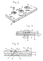
- FIG. 1 is a perspective view of a nozzle plate and nozzles therein, depicting an emerging droplet of ink from a nozzle and a puddle of ink associated therewith;
- FIG. 2 is a cross-section taken along the line 2-2 of FIG. 1, showing the structure of one particular drop generator; and
- FIG. 3 is a view similar to that of FIG. 2, showing a portion of an ink-filled drop generator with a bulging meniscus and a drop of ink wetting the nozzle plate at characteristic wetting angle ϑw.
- Referring now to the drawings wherein like numerals of reference designate like elements throughout, a portion of a printhead is depicted in FIG. 1. In particular is seen a
nozzle plate 10 in which are recessed a plurality ofnozzles 12 in individual recesses 13.Ink 14 is fired from resistors through the nozzles in a particular arrangement toward a print medium (e.g., paper) to form alphanumeric characters and graphics. - FIG. 2 depicts a portion of a
feed chamber 16 in which is located aresistor 18; there is one resistor associated with eachnozzle 12. Ink is fed into the feed chambers from a plenum (not shown). Upon receiving a pulse of energy from an external source, theresistor 18 is heated to a level sufficient to expel a droplet ofink 14 toward the print medium. Following ejection of theink droplet 14, additional ink fills thechamber 16 in preparation for another firing. - The
nozzle 12 has a nozzle diameter d; each resistor covers a square area with side dimension s; the channel width is given by w. The thickness of thenozzle plate 10 is tp, while the thickness ofbarrier layer 20 is tb. In a preferred example, the printhead employs abarrier layer 20 comprising Vacrel 55 µm thick and anozzle plate 10 comprising gold-plated nickel 63 µm thick. Thenozzles 12 are 47 ±3 µm diameter, with resistors 64 µm x 64 µm, and channel width 84 µm wide. - As indicated in the Background Art section, during the overshoot phase, a puddle 22 of ink may form adjacent the
nozzle 12. If not wicked back into the chamber, such a puddle may have a deleterious effect upon print quality by interfering with thedroplet 14 of ink as it is ejected from thenozzle 12. - During the refill process, the meniscus overshoots its equilibrium position, is slowed, stopped, and eventually reversed by the surface tension of the meniscus. The maximum overshoot occurs when the meniscus is stopped. In FIG. 3, ϑ corresponds to the maximum overshoot of the meniscus. The angle ϑ is defined by a tangent to the meniscus surface at the nozzle perimeter and a line drawn parallel to the top plate surface. To avoid spillage onto the top plate, ϑ should be less than ϑw, the characteristic wetting angle for the ink and top plate materials.
- As used herein, a stable drop generator is one that makes drops with consistent trajectories, volumes, speeds, and break-up patterns. In accordance with the invention, this stability becomes more likely as the viscosity is increased. This is because it is the damping effect of viscosity that will balance and control the inertial and surface forces that drive the refill and ejection processes. Unstable drop generators with low viscosity are characterized by chaotic meniscus movement, large meniscus overshoots, erratic spray patterns, and puddles 22.
- This stability can bo measured by looking at the accuracy and consistency of dot placement and size. Stability was measured by looking at line spacing on paper. The odd-numbered nozzles in the pen were fired across the page, forming a set of parallel lines. Then, an identical pattern was made with the even-numbered nozzles on a different part of the page. A vision system then examined the patterns, measuring line spacing uniformity and line width uniformity.
- These measurements of line spacing and width were then combined into an overall "print quality number", with 4 being a perfect grade. Testing at 30°C (the worst-case operating temperature for print quality) revealed that 40% H₂O/60% DEG ink (DEG is diethylene glycol) had a print quality number of 3.2, which was a full two points better than the less viscous 50% H₂O/50% DEG (print quality number of 1.2). Also, considering dot placement only, measurements of cross-scan directionality using the same plot showed that going from an ink viscosity of 5 to 7.5 cp (50/50 water/DEG to 40/60 water/DEG) decreased the variation in angular misdirection by 43%:
TABLE I Printing Results (30°C/70%RH) Ink ambient viscosity cross-scan 3-sigma (%H₂O/DEG) (cp) (degrees) 50/50 5.0 1.20 40/60 7.5 0.69 - Computer modeling of the ink flow in the printhead confirmed the improved stability obtained with the higher viscosity ink modeling of a pen employing 59 µm Vacrel and
nozzles 12 having a diameter of 43 µm and showed that a change in vehicle composition from 50/50 water/DEC to 40/60 water/DEC should result in the following changes in refill time, overshoot, and damping:TABLE II % Change Relative to 50/50 at 30°C Ink Temp. Refill Overshoot Damping 40/60 H₂O/DEG 60°C +2.3% -26.1% +36.9% 40/60 H₂O/DEG 30°C +18.2 -49.3 +67.4 - In another experimental comparison, 50/50 ink evidenced a spear drop onset at 3,500 Hz. (Spear drops are headless, very fast, and usually misdirected; they appear above certain critical frequencies.) 40/60 ink evidenced a spear drop onset at frequencies of about 4,800 Hz, while 30/70 ink evidenced a spear drop onset at frequencies greater than 5,500 Hz.
- In yet another experimental comparison, various compositions of ink were fired from pens with the following results:
TABLE III Properties for Various Viscosities of H₂O/DEG % H₂O Vmin/Vss Directionality Viscosity cp (25°C) 60 0.729 1.5 3.89 50 0.833 4 5.48 40 0.860 7.5 8.61 30 >0.95 9 13.81 20% NMP 0.901 7.5 7.94 Notes: (1) Vmin/Vss is the ratio between the minimum velocity in a frequency resonance plot and the steady state velocity. A value close to 1.0 indicates stability over the frequency range. (2) Directionality is on a scale of 0 to 9, where 0 is bad and 9 is good. (3) 20% NMP = 40% H₂O, 40% DEG, 20% N-methyl pyrrolidone. - Print quality was determined for a variety of compositions, using the preferred printhead configuration given above. The results are listed below, with average print quality given for the indicated vehicle composition. The higher the value, the better the print quality. Each pen has three groups of ten nozzles each; each such group is called a primitive. In the test, a visual determination was made for each half-primitive (the odd or even nozzles), and summed for all six half-primitives to arrive at the average PQ rating. The rating is based on 0 = very poor, 1 = poor, 2 = fair, and 3 = good; values of 2 and above (here, 12.0 and above) are deemed acceptable.
TABLE IV Print Quality vs. % H₂O/DEG H₂O/DEG Ave. PQ Rating 70/30 0.8 60/40 8.0 50/50 11.9 40/60 16.5 30/70 18.0 5% NMP 14.0 10% NMP 13.8 15% NMP 16.0 Note: % NMP plus equal portions of H₂O and DEG - From the foregoing, it is evident that an increase in viscosity of ink improves the print quality considerably. However, there is an upper limit on the viscosity of ink that may be employed, since higher viscosity inks take longer to dry and increase the refill time. Indeed, in conjunction with some print media (e.g., Mylar transparencies), the upper limit is severely constrained. For example, 30/70 H₂O/DEG is useful with paper, but cannot be used with Mylar transparencies.
- Although diethylene glycol was used to increase the viscosity of the inks in the foregoing examples, it will be readily clear to those skilled in this art that the teachings of this invention are applicable to any of the water-miscible glycols typically used in ink-jet printing. Thus, in addition to diethylene glycol, ethylene glycol and propylene glycol are but a few examples of the many glycols that are used in ink-jet printing, and an increase in the glycol content relative to water will accomplish the same purpose, with the same end result as indicated above.
Claims (6)
Applications Claiming Priority (2)
| Application Number | Priority Date | Filing Date | Title |
|---|---|---|---|
| US32921889A | 1989-03-27 | 1989-03-27 | |
| US329218 | 1989-03-27 |
Publications (2)
| Publication Number | Publication Date |
|---|---|
| EP0389738A2 true EP0389738A2 (en) | 1990-10-03 |
| EP0389738A3 EP0389738A3 (en) | 1991-01-09 |
Family
ID=23284398
Family Applications (1)
| Application Number | Title | Priority Date | Filing Date |
|---|---|---|---|
| EP19900100366 Withdrawn EP0389738A3 (en) | 1989-03-27 | 1990-01-09 | Printhead performance tuning via ink viscosity adjustment |
Country Status (3)
| Country | Link |
|---|---|
| EP (1) | EP0389738A3 (en) |
| JP (1) | JPH02281959A (en) |
| CA (1) | CA2006047A1 (en) |
Cited By (7)
| Publication number | Priority date | Publication date | Assignee | Title |
|---|---|---|---|---|
| DE4141203A1 (en) * | 1990-12-14 | 1992-06-17 | Ricoh Kk | Ink jet printer head - has ink ducts etched into plate mounted on heater actuator to generate droplet discharge bubbles |
| DE4223707A1 (en) * | 1991-07-19 | 1993-01-21 | Ricoh Kk | Ink bubble jet printer - has multiple nozzles each with associated heating electrode to generate air bubble causing rapid discharge of defined ink droplet |
| WO2001003933A1 (en) * | 1999-07-14 | 2001-01-18 | Marconi Data Systems Inc. | A droplet generator for a continuous stream ink jet print head |
| EP1195257A1 (en) * | 2000-10-05 | 2002-04-10 | Eastman Kodak Company | Electrical waveform for satellite suppression |
| US6561607B1 (en) | 2000-10-05 | 2003-05-13 | Eastman Kodak Company | Apparatus and method for maintaining a substantially constant closely spaced working distance between an inkjet printhead and a printing receiver |
| US7879408B1 (en) | 1999-06-30 | 2011-02-01 | Metso Paper, Inc. | Method and apparatus for spreading treating agent on a moving web |
| EP3424718A1 (en) * | 2017-06-23 | 2019-01-09 | Canon Kabushiki Kaisha | Liquid ejecting head and liquid ejecting apparatus |
Families Citing this family (5)
| Publication number | Priority date | Publication date | Assignee | Title |
|---|---|---|---|---|
| JPH06286129A (en) * | 1992-02-20 | 1994-10-11 | Seikosha Co Ltd | Ink jet head |
| US6290331B1 (en) | 1999-09-09 | 2001-09-18 | Hewlett-Packard Company | High efficiency orifice plate structure and printhead using the same |
| US6130688A (en) * | 1999-09-09 | 2000-10-10 | Hewlett-Packard Company | High efficiency orifice plate structure and printhead using the same |
| US7594507B2 (en) * | 2001-01-16 | 2009-09-29 | Hewlett-Packard Development Company, L.P. | Thermal generation of droplets for aerosol |
| US9630411B2 (en) * | 2011-04-27 | 2017-04-25 | Koninklijke Philips N.V. | Method of improving the yield of a nozzle plate fabrication process |
Citations (6)
| Publication number | Priority date | Publication date | Assignee | Title |
|---|---|---|---|---|
| FR2404531A1 (en) * | 1977-10-03 | 1979-04-27 | Canon Kk | METHOD AND APPARATUS FOR RECORDING BY INK DROPLET |
| US4330787A (en) * | 1978-10-31 | 1982-05-18 | Canon Kabushiki Kaisha | Liquid jet recording device |
| US4395287A (en) * | 1980-12-01 | 1983-07-26 | Canon Kabushiki Kaisha | Liquid recording material |
| US4675693A (en) * | 1983-01-28 | 1987-06-23 | Canon Kabushiki Kaisha | Liquid injection recording method in which the liquid droplet volume has a predetermined relationship to the area of the liquid discharge port |
| EP0231790A2 (en) * | 1986-01-30 | 1987-08-12 | Hewlett-Packard Company | Process for fabricating laminated structures of improved structural integrity |
| US4752784A (en) * | 1986-06-10 | 1988-06-21 | Fuji Xerox Co., Ltd. | Thermal electrostatic ink-jet recording method |
-
1989
- 1989-12-19 CA CA 2006047 patent/CA2006047A1/en not_active Abandoned
-
1990
- 1990-01-09 EP EP19900100366 patent/EP0389738A3/en not_active Withdrawn
- 1990-03-23 JP JP7536590A patent/JPH02281959A/en active Pending
Patent Citations (6)
| Publication number | Priority date | Publication date | Assignee | Title |
|---|---|---|---|---|
| FR2404531A1 (en) * | 1977-10-03 | 1979-04-27 | Canon Kk | METHOD AND APPARATUS FOR RECORDING BY INK DROPLET |
| US4330787A (en) * | 1978-10-31 | 1982-05-18 | Canon Kabushiki Kaisha | Liquid jet recording device |
| US4395287A (en) * | 1980-12-01 | 1983-07-26 | Canon Kabushiki Kaisha | Liquid recording material |
| US4675693A (en) * | 1983-01-28 | 1987-06-23 | Canon Kabushiki Kaisha | Liquid injection recording method in which the liquid droplet volume has a predetermined relationship to the area of the liquid discharge port |
| EP0231790A2 (en) * | 1986-01-30 | 1987-08-12 | Hewlett-Packard Company | Process for fabricating laminated structures of improved structural integrity |
| US4752784A (en) * | 1986-06-10 | 1988-06-21 | Fuji Xerox Co., Ltd. | Thermal electrostatic ink-jet recording method |
Cited By (12)
| Publication number | Priority date | Publication date | Assignee | Title |
|---|---|---|---|---|
| DE4141203A1 (en) * | 1990-12-14 | 1992-06-17 | Ricoh Kk | Ink jet printer head - has ink ducts etched into plate mounted on heater actuator to generate droplet discharge bubbles |
| US5389962A (en) * | 1990-12-14 | 1995-02-14 | Ricoh Company, Ltd. | Ink jet recording head assembly |
| DE4223707A1 (en) * | 1991-07-19 | 1993-01-21 | Ricoh Kk | Ink bubble jet printer - has multiple nozzles each with associated heating electrode to generate air bubble causing rapid discharge of defined ink droplet |
| US5754202A (en) * | 1991-07-19 | 1998-05-19 | Ricoh Company, Ltd. | Ink jet recording apparatus |
| US7879408B1 (en) | 1999-06-30 | 2011-02-01 | Metso Paper, Inc. | Method and apparatus for spreading treating agent on a moving web |
| WO2001003933A1 (en) * | 1999-07-14 | 2001-01-18 | Marconi Data Systems Inc. | A droplet generator for a continuous stream ink jet print head |
| US6637871B1 (en) | 1999-07-14 | 2003-10-28 | Videojet Technologies, Inc. | Droplet generator for a continuous stream ink jet print head |
| EP1195257A1 (en) * | 2000-10-05 | 2002-04-10 | Eastman Kodak Company | Electrical waveform for satellite suppression |
| US6428135B1 (en) | 2000-10-05 | 2002-08-06 | Eastman Kodak Company | Electrical waveform for satellite suppression |
| US6561607B1 (en) | 2000-10-05 | 2003-05-13 | Eastman Kodak Company | Apparatus and method for maintaining a substantially constant closely spaced working distance between an inkjet printhead and a printing receiver |
| EP3424718A1 (en) * | 2017-06-23 | 2019-01-09 | Canon Kabushiki Kaisha | Liquid ejecting head and liquid ejecting apparatus |
| US10661565B2 (en) | 2017-06-23 | 2020-05-26 | Canon Kabushiki Kaisha | Liquid ejecting head and liquid ejecting apparatus |
Also Published As
| Publication number | Publication date |
|---|---|
| EP0389738A3 (en) | 1991-01-09 |
| CA2006047A1 (en) | 1990-09-27 |
| JPH02281959A (en) | 1990-11-19 |
Similar Documents
| Publication | Publication Date | Title |
|---|---|---|
| US4882595A (en) | Hydraulically tuned channel architecture | |
| US6712454B2 (en) | Ink jet recording head and ink jet recording apparatus | |
| EP1024008B1 (en) | Liquid ejection head, method for preventing accidental non-ejection using the ejection head and manufacturing method of the ejection head | |
| US7063415B2 (en) | Liquid jet apparatus using a fine particle dispersion liquid composition | |
| US7802874B2 (en) | Restrictors with structure to prevent back flow and inkjet head having the same | |
| EP0314486A2 (en) | Hydraulically tuned channel architecture | |
| EP0389738A2 (en) | Printhead performance tuning via ink viscosity adjustment | |
| US7735962B2 (en) | Ink jet print head | |
| EP0737581A2 (en) | Liquid ejecting head, liquid ejecting device and liquid ejecting method | |
| EP1024003B1 (en) | Ink jet recording head with improved ink supply channels | |
| JP2004090504A (en) | Liquid droplet jetting head and liquid droplet jetting apparatus | |
| EP1356937B1 (en) | Ink jet head | |
| KR100251132B1 (en) | Ink jet printer head using membrane | |
| KR100589575B1 (en) | Liquid ejection head and image-forming apparatus using the same | |
| US6578954B2 (en) | Ink jet printing head and ink jet printing device enabling stable high-frequency ink drop ejection and high-speed printing | |
| KR101056321B1 (en) | Droplet ejection device | |
| US20200290350A1 (en) | Nozzle geometry for printheads | |
| EP0764528A2 (en) | Liquid discharging method, liquid discharging head, liquid discharging apparatus, liquid container and head cartridge | |
| JPH11291500A (en) | Liquid delivery method and liquid delivery head | |
| EP0819539A2 (en) | Liquid ejecting head and head cartridge capable of adjusting energy supplied thereto, liquid ejecting device provided with the head and head cartridge, and recording system | |
| JP3571856B2 (en) | Liquid ejection head and liquid ejection device | |
| JPH07195697A (en) | Ink jet recording head, method and apparatus for ink jet recording | |
| JPH07329301A (en) | Ink jet recording head, ink jet recorder and data processing system | |
| JP4232517B2 (en) | Droplet discharge head and droplet discharge apparatus | |
| JPH03292145A (en) | Ink-jet recording device |
Legal Events
| Date | Code | Title | Description |
|---|---|---|---|
| PUAI | Public reference made under article 153(3) epc to a published international application that has entered the european phase |
Free format text: ORIGINAL CODE: 0009012 |
|
| AK | Designated contracting states |
Kind code of ref document: A2 Designated state(s): DE FR GB IT NL |
|
| PUAL | Search report despatched |
Free format text: ORIGINAL CODE: 0009013 |
|
| AK | Designated contracting states |
Kind code of ref document: A3 Designated state(s): DE FR GB IT NL |
|
| 17P | Request for examination filed |
Effective date: 19910313 |
|
| STAA | Information on the status of an ep patent application or granted ep patent |
Free format text: STATUS: THE APPLICATION HAS BEEN WITHDRAWN |
|
| 18W | Application withdrawn |
Withdrawal date: 19910919 |
|
| R18W | Application withdrawn (corrected) |
Effective date: 19910919 |