EP0390202A2 - Ink jet recording head, driving method for same and ink jet recording apparatus - Google Patents
Ink jet recording head, driving method for same and ink jet recording apparatus Download PDFInfo
- Publication number
- EP0390202A2 EP0390202A2 EP90106174A EP90106174A EP0390202A2 EP 0390202 A2 EP0390202 A2 EP 0390202A2 EP 90106174 A EP90106174 A EP 90106174A EP 90106174 A EP90106174 A EP 90106174A EP 0390202 A2 EP0390202 A2 EP 0390202A2
- Authority
- EP
- European Patent Office
- Prior art keywords
- recording
- ink
- ejection
- eject
- enough
- Prior art date
- Legal status (The legal status is an assumption and is not a legal conclusion. Google has not performed a legal analysis and makes no representation as to the accuracy of the status listed.)
- Granted
Links
Images


Classifications
-
- B—PERFORMING OPERATIONS; TRANSPORTING
- B41—PRINTING; LINING MACHINES; TYPEWRITERS; STAMPS
- B41J—TYPEWRITERS; SELECTIVE PRINTING MECHANISMS, i.e. MECHANISMS PRINTING OTHERWISE THAN FROM A FORME; CORRECTION OF TYPOGRAPHICAL ERRORS
- B41J2/00—Typewriters or selective printing mechanisms characterised by the printing or marking process for which they are designed
- B41J2/005—Typewriters or selective printing mechanisms characterised by the printing or marking process for which they are designed characterised by bringing liquid or particles selectively into contact with a printing material
- B41J2/01—Ink jet
- B41J2/015—Ink jet characterised by the jet generation process
- B41J2/04—Ink jet characterised by the jet generation process generating single droplets or particles on demand
- B41J2/045—Ink jet characterised by the jet generation process generating single droplets or particles on demand by pressure, e.g. electromechanical transducers
- B41J2/04501—Control methods or devices therefor, e.g. driver circuits, control circuits
- B41J2/04528—Control methods or devices therefor, e.g. driver circuits, control circuits aiming at warming up the head
-
- B—PERFORMING OPERATIONS; TRANSPORTING
- B41—PRINTING; LINING MACHINES; TYPEWRITERS; STAMPS
- B41J—TYPEWRITERS; SELECTIVE PRINTING MECHANISMS, i.e. MECHANISMS PRINTING OTHERWISE THAN FROM A FORME; CORRECTION OF TYPOGRAPHICAL ERRORS
- B41J2/00—Typewriters or selective printing mechanisms characterised by the printing or marking process for which they are designed
- B41J2/005—Typewriters or selective printing mechanisms characterised by the printing or marking process for which they are designed characterised by bringing liquid or particles selectively into contact with a printing material
- B41J2/01—Ink jet
- B41J2/015—Ink jet characterised by the jet generation process
- B41J2/04—Ink jet characterised by the jet generation process generating single droplets or particles on demand
- B41J2/045—Ink jet characterised by the jet generation process generating single droplets or particles on demand by pressure, e.g. electromechanical transducers
- B41J2/04501—Control methods or devices therefor, e.g. driver circuits, control circuits
- B41J2/04541—Specific driving circuit
-
- B—PERFORMING OPERATIONS; TRANSPORTING
- B41—PRINTING; LINING MACHINES; TYPEWRITERS; STAMPS
- B41J—TYPEWRITERS; SELECTIVE PRINTING MECHANISMS, i.e. MECHANISMS PRINTING OTHERWISE THAN FROM A FORME; CORRECTION OF TYPOGRAPHICAL ERRORS
- B41J2/00—Typewriters or selective printing mechanisms characterised by the printing or marking process for which they are designed
- B41J2/005—Typewriters or selective printing mechanisms characterised by the printing or marking process for which they are designed characterised by bringing liquid or particles selectively into contact with a printing material
- B41J2/01—Ink jet
- B41J2/015—Ink jet characterised by the jet generation process
- B41J2/04—Ink jet characterised by the jet generation process generating single droplets or particles on demand
- B41J2/045—Ink jet characterised by the jet generation process generating single droplets or particles on demand by pressure, e.g. electromechanical transducers
- B41J2/04501—Control methods or devices therefor, e.g. driver circuits, control circuits
- B41J2/04543—Block driving
-
- B—PERFORMING OPERATIONS; TRANSPORTING
- B41—PRINTING; LINING MACHINES; TYPEWRITERS; STAMPS
- B41J—TYPEWRITERS; SELECTIVE PRINTING MECHANISMS, i.e. MECHANISMS PRINTING OTHERWISE THAN FROM A FORME; CORRECTION OF TYPOGRAPHICAL ERRORS
- B41J2/00—Typewriters or selective printing mechanisms characterised by the printing or marking process for which they are designed
- B41J2/005—Typewriters or selective printing mechanisms characterised by the printing or marking process for which they are designed characterised by bringing liquid or particles selectively into contact with a printing material
- B41J2/01—Ink jet
- B41J2/015—Ink jet characterised by the jet generation process
- B41J2/04—Ink jet characterised by the jet generation process generating single droplets or particles on demand
- B41J2/045—Ink jet characterised by the jet generation process generating single droplets or particles on demand by pressure, e.g. electromechanical transducers
- B41J2/04501—Control methods or devices therefor, e.g. driver circuits, control circuits
- B41J2/04553—Control methods or devices therefor, e.g. driver circuits, control circuits detecting ambient temperature
-
- B—PERFORMING OPERATIONS; TRANSPORTING
- B41—PRINTING; LINING MACHINES; TYPEWRITERS; STAMPS
- B41J—TYPEWRITERS; SELECTIVE PRINTING MECHANISMS, i.e. MECHANISMS PRINTING OTHERWISE THAN FROM A FORME; CORRECTION OF TYPOGRAPHICAL ERRORS
- B41J2/00—Typewriters or selective printing mechanisms characterised by the printing or marking process for which they are designed
- B41J2/005—Typewriters or selective printing mechanisms characterised by the printing or marking process for which they are designed characterised by bringing liquid or particles selectively into contact with a printing material
- B41J2/01—Ink jet
- B41J2/015—Ink jet characterised by the jet generation process
- B41J2/04—Ink jet characterised by the jet generation process generating single droplets or particles on demand
- B41J2/045—Ink jet characterised by the jet generation process generating single droplets or particles on demand by pressure, e.g. electromechanical transducers
- B41J2/04501—Control methods or devices therefor, e.g. driver circuits, control circuits
- B41J2/04563—Control methods or devices therefor, e.g. driver circuits, control circuits detecting head temperature; Ink temperature
-
- B—PERFORMING OPERATIONS; TRANSPORTING
- B41—PRINTING; LINING MACHINES; TYPEWRITERS; STAMPS
- B41J—TYPEWRITERS; SELECTIVE PRINTING MECHANISMS, i.e. MECHANISMS PRINTING OTHERWISE THAN FROM A FORME; CORRECTION OF TYPOGRAPHICAL ERRORS
- B41J2/00—Typewriters or selective printing mechanisms characterised by the printing or marking process for which they are designed
- B41J2/005—Typewriters or selective printing mechanisms characterised by the printing or marking process for which they are designed characterised by bringing liquid or particles selectively into contact with a printing material
- B41J2/01—Ink jet
- B41J2/015—Ink jet characterised by the jet generation process
- B41J2/04—Ink jet characterised by the jet generation process generating single droplets or particles on demand
- B41J2/045—Ink jet characterised by the jet generation process generating single droplets or particles on demand by pressure, e.g. electromechanical transducers
- B41J2/04501—Control methods or devices therefor, e.g. driver circuits, control circuits
- B41J2/0458—Control methods or devices therefor, e.g. driver circuits, control circuits controlling heads based on heating elements forming bubbles
-
- B—PERFORMING OPERATIONS; TRANSPORTING
- B41—PRINTING; LINING MACHINES; TYPEWRITERS; STAMPS
- B41J—TYPEWRITERS; SELECTIVE PRINTING MECHANISMS, i.e. MECHANISMS PRINTING OTHERWISE THAN FROM A FORME; CORRECTION OF TYPOGRAPHICAL ERRORS
- B41J2/00—Typewriters or selective printing mechanisms characterised by the printing or marking process for which they are designed
- B41J2/005—Typewriters or selective printing mechanisms characterised by the printing or marking process for which they are designed characterised by bringing liquid or particles selectively into contact with a printing material
- B41J2/01—Ink jet
- B41J2/015—Ink jet characterised by the jet generation process
- B41J2/04—Ink jet characterised by the jet generation process generating single droplets or particles on demand
- B41J2/045—Ink jet characterised by the jet generation process generating single droplets or particles on demand by pressure, e.g. electromechanical transducers
- B41J2/04501—Control methods or devices therefor, e.g. driver circuits, control circuits
- B41J2/04581—Control methods or devices therefor, e.g. driver circuits, control circuits controlling heads based on piezoelectric elements
-
- B—PERFORMING OPERATIONS; TRANSPORTING
- B41—PRINTING; LINING MACHINES; TYPEWRITERS; STAMPS
- B41J—TYPEWRITERS; SELECTIVE PRINTING MECHANISMS, i.e. MECHANISMS PRINTING OTHERWISE THAN FROM A FORME; CORRECTION OF TYPOGRAPHICAL ERRORS
- B41J2/00—Typewriters or selective printing mechanisms characterised by the printing or marking process for which they are designed
- B41J2/005—Typewriters or selective printing mechanisms characterised by the printing or marking process for which they are designed characterised by bringing liquid or particles selectively into contact with a printing material
- B41J2/01—Ink jet
- B41J2/015—Ink jet characterised by the jet generation process
- B41J2/04—Ink jet characterised by the jet generation process generating single droplets or particles on demand
- B41J2/045—Ink jet characterised by the jet generation process generating single droplets or particles on demand by pressure, e.g. electromechanical transducers
- B41J2/04501—Control methods or devices therefor, e.g. driver circuits, control circuits
- B41J2/04588—Control methods or devices therefor, e.g. driver circuits, control circuits using a specific waveform
-
- B—PERFORMING OPERATIONS; TRANSPORTING
- B41—PRINTING; LINING MACHINES; TYPEWRITERS; STAMPS
- B41J—TYPEWRITERS; SELECTIVE PRINTING MECHANISMS, i.e. MECHANISMS PRINTING OTHERWISE THAN FROM A FORME; CORRECTION OF TYPOGRAPHICAL ERRORS
- B41J2/00—Typewriters or selective printing mechanisms characterised by the printing or marking process for which they are designed
- B41J2/005—Typewriters or selective printing mechanisms characterised by the printing or marking process for which they are designed characterised by bringing liquid or particles selectively into contact with a printing material
- B41J2/01—Ink jet
- B41J2/135—Nozzles
- B41J2/14—Structure thereof only for on-demand ink jet heads
- B41J2002/14379—Edge shooter
-
- B—PERFORMING OPERATIONS; TRANSPORTING
- B41—PRINTING; LINING MACHINES; TYPEWRITERS; STAMPS
- B41J—TYPEWRITERS; SELECTIVE PRINTING MECHANISMS, i.e. MECHANISMS PRINTING OTHERWISE THAN FROM A FORME; CORRECTION OF TYPOGRAPHICAL ERRORS
- B41J2202/00—Embodiments of or processes related to ink-jet or thermal heads
- B41J2202/01—Embodiments of or processes related to ink-jet heads
- B41J2202/21—Line printing
Definitions
- the present invention relates to an ink jet recording head, a driving method for the same and an ink jet recording apparatus wherein ink is ejected to record information on a recording material.
- the recording apparatus using the driving method for the ink jet recording head according to this invention is usable, for example, with a printer as peripheral equipment of information processing apparatus such as computer, a copying apparatus having a reader, a wordprocessor having key input function, an electronic typewriter and a facsimile machine having information transmitting and receiving function.
- the ink jet recording apparatus using heat as energy for the formation of the droplets has a good advantage that the recording head therefor can be easily formed as multi-nozzle head having a number of nozzles at high density, and therefore, high resolution and high quality images can be produced at a high speed.
- the recording head thereof is of a so-called full- multi-type in which the ejection outlets are disposed to cover the entire width of the recording material (line printer recording head), wherein on one and the same substrate, there are disposed plural liquid droplet forming means for ejecting ink droplets through ejection outlets by application of thermal energy, that is, droplet forming means including electrothermal transducers for producing heat to heat the ink by supplying electric current pulses, and corresponding number of integrated circuits (driver IC) for driving the electrothermal transducers.
- droplet forming means including electrothermal transducers for producing heat to heat the ink by supplying electric current pulses, and corresponding number of integrated circuits (driver IC) for driving the electrothermal transducers.
- Figure 1 shows an example of electric structure of the ink jet recording head of this type.
- Figure 2 shows driving timing thereof.
- the recording data (SI: 13-b) having the same bit number as the electrothermal transducer 7 are sequentially supplied to a shift register 4 in the driver IC3 in sychronism with a data transfer clock (CLK). After all the data are transferred, they are read in a latching circuit 5 in response to a latching signal (LAT).
- SI: 13-b The recording data (SI: 13-b) having the same bit number as the electrothermal transducer 7 are sequentially supplied to a shift register 4 in the driver IC3 in sychronism with a data transfer clock (CLK). After all the data are transferred, they are read in a latching circuit 5 in response to a latching signal (LAT).
- CLK data transfer clock
- a flip-flop circuit (F/F) 6 activates sequentially the driver IC IC3, by which the electrothermal transducers 7 for which the recording data signals are "ON” are selectively energized only during the ON-state of the pulsewidth setting signal (ENB) so as to eject the liquid.
- the recording liquid which will hereinafter be called "ink” is directly ejected from the ejection outlet of the recording head, and therefore, particular considerations which are not necessary in the other type recording apparatus are required in order to maintain the ink under ejectable state at all times.
- the ink remains in the liquid passage of the recording head when the recording operation is not effected, some measure is required, as the case may be, to prevent change in the property of the ink such as increase of the viscosity attributable to the drying and/or evaporation of the ink in the liquid passage.
- a measure is known wherein the recording head is provided with a so-called capping means to cover the ejection outlets of the recording head when the recording operation is not performed to prevent the ink from drying or evaporating.
- the air in the cap covering the recording head is sucked to impart negative pressure to the ejection outlets to suck in the ink out of the liquid passages.
- pressure is applied to the ink supply system using a pump to eject the ink having been changed in its property through the ejection outlets.
- the ink is ejected (idle ejection) to the portion other than the recording material, for example, to the capping means from all of the ejection outlets to forcedly discharge the ink having increased viscosity in the passage.
- the means for doing such measures are called a recovery system.
- the recovery mechanism is automatically driven upon actuation of a main switch, and that during the recording operation it is driven at as long as possible intervals, in order to reduce the consumption of the ink.
- the recording operation is interrupted at short intervals to perform the ejection recovery process. This, however, decreases the recording speed.
- the electrothermal transducers are energized to such an extent that the ink is not ejected when the ejection signals are not supplied thereto, thus heating the ink therein (preliminary heating) in order to maintain the temperature of the ink within a predetermined range.
- preliminary heating Various methods for accomplishing this are proposed.
- the present invention is a further improvement of the above-mentioned proposals.
- the ink jet recording apparatus comprises a recording head having a plurality of electrothermal transducers for producing thermal energy contributable to the ink ejection, ejecting drive means for supplying drive signals to the electrothermal transducers of the recording head in accordance with the data to be recorded to eject the ink, and heat driving means for supplying a drive signal enough to heat the ink but not enough to eject the ink to the electrothermal transducers after each unit driving operations by said ejection driving means.
- the plurality of electrothermal transducers of the recording head are supplied alternately with driving signals corresponding to the data to be recorded and the heating drive signals not enough to the eject the ink.
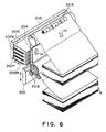
- FIG. 3 there is shown in a partly broken perspective view an ink jet recording head to which the present invention is applicable.
- the recording head is of a so-called full-multi-type in which the ejection outlets are aligned in a range covering the entire width of the recording material.
- the recording head includes heat generating resistors 54 constituting the electrothermal transducer elements 7 for producing heat upon electric energy application thereto to produce film boiling so as to form a bubble in the ink to eject the ink.
- the ink is ejected by the development and contraction of the bubble.
- the heat generating resistors 54 are formed on a substrate 51 through a manufacturing process which is similar to a semiconductor manufacturing process, the recording head further comprising liquid passage forming portions, corresponding to the heat generating resistors 54.
- the portions 52A are effective to form ejection outlets 52 and liquid passages 53 communicating therewith, respectively.
- a top plate 56 covers the liquid passage forming portions to form the liquid passages.
- a liquid chamber 55 communicates commonly all of the liquid passages 53 and store in the recording head the ink supplied from an unshown ink supply source.
- FIG 4A shows an example of a drive control system for heat-driving the ink jet recording head in accordance with image information, the ink jet recording head 1 having the mechanical structure shown in Figure 3.
- the control system comprises a head driving circuit 2 according to this embodiment.
- the heat driving circuit 2 includes a head driving electric power source 8, a timing generating circuit 9, a gate circuit 10, a preliminary heating data generating circuit 11 and a recording data/drive timing generating circuit 12.
- the timing generating circuit 9 produces a pulse width setting signal END, a divided drive signal EZ, a divided drive signal transfer clock ECK and a latching signal LAT in accordance with control signals C1 and C2 of the recording data/drive timing generating circuit 12, and they are supplied to the driver IC (integrated circuit) IC3 of the recording head.
- the preliminary heating data generating circuit 11 receives the recording data SI for one line from the recording data/drive timing generating circuit 12 in response to the control signal C2, and it stores as preliminary heating data the data provided by reversing the received data, and it produces the preliminary heating data after ejection drive for one line.
- the gate circuit 10 receives the recording data for one line from the recording data/drive timing generating circuit 12 and the preliminary heating data from the preliminary heating data generating circuit 11, and transfers them to a shift register 4.
- the recording data/drive timing generating circuit 12 sequentially outputs the recording data for one line to perform the ejection drive for ejecting the ink, and during the drive, the preliminary heating data generating circuit 11 produces the preliminary heating data to perform the preliminary heating drive. Therefore, in this embodiment, the ejection drives and the preliminary heating drives are alternately carried out.
- the preliminary heating drive is performed entirety or partly using the recording material feeding period after completion of the recording on one recording line, whereby the recording throughput does not significantly decrease.
- Designated by a reference numeral 24 is an AND circuit.
- a controller 20 controls the entire recording apparatus and comprises a CPU (central processing unit) such as a microprocessor, ROM 21 for storing control program for the CPU 20 and various data, RAM 22 used as a working area of the CPU 20 and I/O ports 23. They are electrically connected by a bus line 24, wherein the record control data are supplied to the recording data/drive timing generating circuit 12.
- An ambient temperature detecting element TH is formed on the head substrate to detect all or part of the temperature of the head, the external temperature and the like and supplies the detected temperature information to the timing generating circuit 9. Therefore, the preliminary heating at the time of the initial start can be performed in accordance with the ambient temperature.
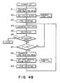
- Figure 4B is a flow chart illustrating the operation of the drive control of the circuit shown in Figure 4A.
- the preliminary heating data are transferred to the shift register 4 from the preliminary heating data generating circuit 11 through a gate 10 (step S1).
- the temperature information is supplied to the timing generating circuit 9 from the ambient temperature detecting element TH.
- the pulsewidth setting signal ENB which is dependent on the temperature information is supplied to the driver IC3 of the recording head 1 (step S2).
- the preliminary heating depending on the ambient temperature is effected for all of the nozzles, at the time of the initial starting operation (step S3).
- the recording data S1 for one line are transferred to the shift register 4 from the recording data/drive timing generating circuit 12 (step S4).
- step S5 selected electrothermal transducers 7 produce heat to eject the ink through the corresponding ejection outlets. If the next recording data are not transferred even after a predetermined time period elapses, the recording operation ends (step S6).
- the recording data S1 are transferred for N lines sequentially (N ⁇ 1), and the recording for the N lines is completed, the preliminary heating data are transferred from the preliminary heating data generating circuit 11 to the shift register 4 through the gate circuit 10 (steps S7 and S8).
- a predetermined pulsewidth setting signal ENB is supplied to the driver IC3 of the recording head 1 from the timing generating circuit 9, so that the preliminary heating operation is carried out during the recording operation (steps S9 and S10).
- the preliminary heating during the recording operation is not limited to the operation with a predetermined constant pulse width, but it may be performed with the pulse width which is dependent on the ambient temperature similarly to the preliminary heating at the time of the initial starting operation (main switch "ON"). In many cases, the pulse width during the recording is smaller than the pulse width for the preliminary heating during the start-up operation.
- the recording data signal S1 transmitted to the ink jet recording head 1 includes the recording data (13-b) having the same bit number as the electrothermal transducer elements 7 and the preliminary heating data (13-a) which are obtained by reversing the recording data.
- the ink jet recording head 1 is supplied alternately with the preliminary heating data 13-a and the recording data 13-b. After either of the data are received and are aligned in the shift register 4, they are read in the latching circuit 5 in the driver IC3 by the latching signal LAT.
- the driver IC3 is sequentially activated, by which the electrothermal transducer 7 is selectively energized only during on-state of the pulse width setting signal ENB, by which the preliminary heating or the ink ejection is performed. Using the period, the shift register 4 receives the recording data or the preliminary heating data for the next line.
- the pulse width of the pulse width setting signal ENB is such that the ink is not ejected when the pulse is for the preliminary heating (for example, approximately 0.5 - 5 micro-sec), and therefore, the pulse width is smaller than the pulse width during the ejection drive (recording operation) (approximately 3 - 10 micro-sec, for example).
- the preliminary heating data during the recording operation are the data provided by reversing the recording data for the previous line. However, upon the initial recording after the main switch is closed or when the resting period is long, the preliminary heating data is such data as to energize all the electrothermal transducer element 7. Therefore, all the liquid passages are assured to be subjected to the preliminary heating upon the initial recording after the main switch is actuated or after a long resting period.
- the preliminary heating data during the recording operation are not limited to the data obtained by reversing the recording data for the previous line, and may be properly determined by one skilled in the art within the limitation that the effects of the preliminary heating do not disappear.
- the preliminary heating is executed only in the electrothermal transducer or transducers 7 which have been kept unenergized in continuous N lines. Further alternatively, it is possible that the preliminary heating is effected for all of the liquid passages every N lines of recording operations.
- the printer comprises a pair of rollers 201A and 201B constituting a nip therebetween to feed the recording material R (coated paper, plain paper, plastic resin sheet or the like) in a subordinate scanning direction Vs. It also comprises full-multi-type recording heads 202BK, 202Y, 202M and 202C for the black, yellow, magenta and cyan colors, respectively. Each of the recording heads has a number of nozzles enough to cover the entire width of the recording material R.
- the recording heads are mounted on the head mount 203 and are disposed in the order named from the upstream side in the direction of the recording material feed.
- Each of the recording heads has the structure similar to that shown in Figures 3 and 4, and therefore, the above-described drive control is performed.
- the printer is provided with a recovery system 200 which is faced to the recording heads 202BK, 202Y, 202M and 202C in place of the recording medium R when the ejection recovery process is executed. More particularly, the head mount 203 is retracted, and the recovery system 200 enters the space provided by the retraction of the mount 203. Then, sucking operation or other non-recovery operations are performed. In this embodiment, the preliminary heating operation is carried out at proper intervals, and therefore, the number of ejection recovery operations can be remarkably reduced.
- a platen 204 functions to the gap between the recording material R and the ejection outlet of the recording head 202.
- the circuits for the driver IC may be of bi-polar, MOS type, BiCMOS type or the like, as desired.
- the recording head is not limited to that of the full-multi-type described above, it may be of a serial scan type.
- the method for applying to the electrothermal transducers the energy not enough to eject the liquid during the preliminary heating is not limited to the reduction of the pulse width as in the foregoing embodiment. It may be that the drive voltage in place of or in addition to the pulse width change may be changed. In any case, the electric power therefore is smaller than the electric power applied to the recording head for the recording operation.
- the electrothermal transducers 7 are grouped into a predetermined number of groups, and the groups are sequentially driven. If the number of the electrothermal transducers 7 is relatively small, or when the driving power source has sufficient power, it is not inevitable to carry out the divided driving operations, and all of the electrothermal transducers may be driven simultaneously.
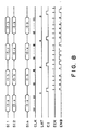
- FIG. 7 a structure for accomplishing a further high speed recording is shown, wherein the recording data are grouped to a desired number of blocks SI1 - SIn.
- the recording data are supplied to the driver IC devices 3 for the respective blocks SI1 - SIn, by which the operation can be performed at the times shown in Figure 8.
- the data to be recorded (recording data) and the preliminary heating data are alternately supplied to carry out the liquid ejections and the preliminary heating operations alternately, by which the electrothermal transducer element corresponding to the ejection outlet through which improper ejection occurs due to lack or short of the ejection drive can be supplied with electric energy by the preliminary heating data. Therefore, the temperatures in all the liquid passages become uniform, so that good recording can be provided. In addition, the intervals of the recovery operations can be reduced, by which the overall recording speed is increased.
- the ink jet recording head which will be described includes a plurality of electrothermal transducer element producing thermal energy contributable to the ink ejection and driving means having a plurality of parallel current limiting elements connected to the electrothermal transducers for selecting in accordance with the data supplied thereto the current limiting element to permit the electrothermal transducers to be supplied with electric power enough to eject the ink or select the current limiting elements to supply the electric current not enough to eject the ink.
- the driving device which will be described is used with the ink jet recording head having a plurality of electrothermal transducers for producing thermal energy contributable to the ink ejection, and comprises driving means including parallel current limiting element connected to an electrothermal transducer to select in accordance with the data received thereby one of the current limiting element for permitting the electrothermal transducer to be supplied with electric power enough to eject the ink and for selecting another current limiting element for supplying electric current not enough to eject the ink.
- the ink jet recording apparatus for recording on the recording material by ink ejection which will be described, comprises an ink jet recording head provided with a plurality of electrothermal transducers for producing thermal energy contributable to the ink ejection, and driving means having plural electric current limiting elements connected to each of electrothermal transducer element, wherein the driving means selects one of the current limiting elements to permit the associated electrothermal transducer element to be supplied with electric energy enough for the ink ejection, or another current limiting element to supply it with the current not enough for the ink ejection.
- the current flows through the selected current limiting element and the electrothermal transducer element connected thereto, in accordance with the data signal applied thereto.
- the preliminary heating drive and the ejection drive can be properly selected.
- Figure 9 shows an electrical structure of the recording head having the mechanical structure shown in Figure 3.
- the driving circuit is integral with the substrate.
- the electrothermal transducer element 7 is connected to driving element 102-1 and 102-2 in the form of transistors in the driver IC8 through a current limiting resistor 101-1 having resistance of Ra and an electric current limiting resistor 101-2 having a resistance of Rb.
- An AND circuit 103 receives an output of a flip-flop circuit 106 and the pulse width setting signal ENB.
- the AND circuit is provided corresponding to each of the driving elements 102-1 and the driving elements 102-2.
- One electrothermal transducer 7 is driven by data having the same bit number as the driving element (2 bits in this embodiment). To accomplish this, the latching circuit 85 and the shift register 4 have the corresponding structure.
- the data signal SI constituted by the same number of bits as the driving element 102 is sequentially supplied to the shift register 84 by the data transfer clock signals CLK, and is read in the latching circuit 85 by the latching signals LAT.
- the driver IC80 are sequentially activated, and the driving element 102-1 and/or 102-2 is selectively actuated only during the on-state of the pulse width setting signal ENB.
- Each of the electrothermal transducers 7 corresponds to the data having the same bit number as the number of the driving elements connected thereto. In this embodiment it is driven by two bit data.
- the resistances Ra and Rb of the current limiting resistors 101-1 and 101-2 are set such that the current I11 sufficient to eject the liquid, whereas the currents I01 and I10 are not sufficient to eject the liquid. Therefore, the current flowing through the electrothermal transducer element 7 can be selected from the three levels in accordance with the input data. Accordingly, the driving operations for the preliminary heating and the liquid ejection can be selected for each of the ejection outlets only by the input data.
- the structure and the operation of the drive limiting means 100 for transmitting bias signals to such driving circuits to control the drive are as follows. For example, when a signal for liquid ejection drive for a certain electrothermal transducer element 7 on the basis of the recording data in which one bit corresponds to one ejection outlet, is "1", the data (1, 1) are produced; and when it is "0", the data (1, 0) or (0, 1) are produced.
- the driving condition or conditions for the preliminary heating can be changed in accordance with the non-ejection-drive period of the electrothermal transducer 7 or the position thereof.
- the larger current is flown immediately after the main switch is actuated or after a long rest-period.
- the preliminary heating drive can be simultaneously effected during the one line recording operation. Alternatively, it may be performed for each several lines. Further alternatively, it can be performed at different timing from the ejection drive.
- the line printer capable of full-color recording shown in Figure 6 described hereinbefore can be constructed, for example.
- the circuit of the driver IC may be of a bipolar type, MOS type, BiCMOS type or the like.
- the recording head is not limited to the full-multi-type as in the foregoing embodiments, but may be a serial scan type.
- the two driving elements are connected to each of the electrothermal transducer.
- three or more of the driving elements can be connected in which the liquid ejection driving current and the preliminary heating drive current may be controlled more finely, that is, with a larger number of levels, by properly selecting the resistances of the current limiting resistors.
- the current limiting resistors includes specific resistors disposed between the electrothermal transducer element and the driving elements, but it may be in the form of a wiring resistance of the wiring for connecting the electrothermal transducer and the driving elements.
- the electrothermal transducer elements 7 are grouped into several unit blocks, and the blocks are sequentially driven.
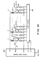
- the number of elements 7 is relatively small, as shown in Figure 10 or when the driving voltage has sufficient capacity, the simultaneous drive is possible in response to a strobe signal STB.
- three current limiting resistors 101-1, 101-2 and 101-3 are employed.
- Figure 1 shows another alternative wherein the power supply lines V H1 - V Hn are provided for the respective blocks, and a common driving system is provided, wherein the divided driving operation is effected.
- a reference 109 is a diode for preventing reverse current.
- Each of the foregoing embodiments is particularly suitable to a bubble jet type recording system among various ink jet recording systems.
- the bubble jet recording system is based on the principle and has the structure as disclosed in U.S. Patents Nos. 4,723,129 and 4,740,796.
- This system is usable with a so-called ON-demand type apparatus and also with a continuous type apparatus.
- the ON-demand type is preferable because the electrothermal transducers disposed faced to the sheet or liquid passages retaining the liquid (ink) are each supplied with at least one driving signals to produce quick temperature rise beyond nuclear boiling in accordance with the recording information, by which the electrothermal transducer produces thermal energy to produce film boiling on the heating surface of the recording head, so that one bubble can be formed in the liquid corresponding to one driving signal.
- the driving signal is preferably in the form of pulses, since then the bubbles are quickly developed and contracted, and therefore, the quick response liquid (ink) ejection can be accomplished.
- the pulse form driving signals are preferably as disclosed in U.S. Patent Nos. 4,463,359 and 4,345,262.
- the temperature rise ratio of the heat applying surface is preferably as disclosed in U.S. Patent No. 4,313,124 to further improve the recording operation.
- the structure of the head may be the combination of the ejection outlet, liquid passage and the electrothermal transducer (linear liquid passage or perpendicularly bent passage) as disclosed in each of the above-mentioned U.S. Patents.
- the heating portion may be disposed at a bent portion as disclosed in U.S. Patents Nos. 4,558,333 and 4,459,660.
- the embodiments described in the foregoing may be used with any of such structures.
- the structure in which the ejecting portions are constituted by slits each of which is common to plural electrothermal transducers, as disclosed in Japanese Laid-Open Patent Application No. 123,670/1984, and the structure wherein an aperture is provided corresponding to the ejection part to absorb the pressure energy of the thermal energy, may be conveniently combined with the present embodiments.
- each of the foregoing embodiments is conveniently incorporated in an exchangeable chip type recording head which can be electrically connected with the main apparatus and can be supplied with the ink from the main assembly by being mounted on the main assembly. It may be conveniently incorporated in a cartridge type recording head.
- Each of the foregoing embodiments may preferably be provided with recovering means for the recording head and/or preliminary auxiliary means, since then, the advantageous effects of each of the foregoing embodiments can be further stabilized.
- the recording mode of the recording apparatus may include a monochromatic recording mode (black or another main color) and in addition it may also contain at least one of a multi-color mode and a full-color mode by an integral recording head or by combination of plural recording heads.
- a monochromatic recording mode black or another main color
- the recording mode of the recording apparatus may also contain at least one of a multi-color mode and a full-color mode by an integral recording head or by combination of plural recording heads.
- the ink is described as liquid. However, it may be the ink which is solid under the room temperature or lower but is softened or liquefied under the temperature higher than the room temperature.
- the temperature of the ink is maintained within a range not lower than 30 °C and not higher than 70 °C, generally in order to maintain the proper viscosity of the ink for the stabilized ejection. Therefore, what is required is that the ink is or becomes liquid upon application of the signal.
- the ink may be such that the thermal energy is consumed for the change of phase from the solid phase to the liquid phase to prevent the temperature rise due to the thermal energy or that the ink is solidified when it is left as it is for the purpose of preventing evaporation of the ink, if the ink is liquefied by the application of thermal energy as the recording signal, and the ink is ejected as liquid.
- the ink may be such that it starts to be solidified at the point of time when it is reaches the recording material.
- Such ink which is liquefied by the application of the thermal energy are usable with the embodiments of the present invention.
- ink When such ink is used, the ink may be retained as liquid or solid material in the through holes or recesses of a porous sheet material, and the sheet material is faced to the electrothermal transducers.
- ink ejection energy producing means is not limited to the above-described electrothermal transducer, but it may be electro-mechanical transducer such as a piezoelectric element or the like, or it may be in the form of electromagnetic wave such as laser which is applied to the liquid and absorbed thereby to produce the heat which is contributable to eject the ink.
- each of the electrothermal transducer elements corresponding to the ejection outlets can be selectively driven for the preliminary heating or for the liquid ejection in accordance with the input data, and therefore, the temperatures of the ejection outlets are made uniform, and the high quality recording is possible with simple structure.
- the intervals of the ejection recovery operations can be extended, and therefore, a high speed recording operation is possible.
- the ink jet recording head a driving method for the same and the ink jet recording apparatus which can record with high recording quality, can be provided.
- a recording method for making record on a recording material by ejection of ink wherein after electric power enough to eject the ink for the recording on the recording material is supplied to recording device to effect the recording in a predetermined region, electric power not enough to eject the ink is supplied to the recording device.
Abstract
Description
- The present invention relates to an ink jet recording head, a driving method for the same and an ink jet recording apparatus wherein ink is ejected to record information on a recording material.
- The recording apparatus using the driving method for the ink jet recording head according to this invention is usable, for example, with a printer as peripheral equipment of information processing apparatus such as computer, a copying apparatus having a reader, a wordprocessor having key input function, an electronic typewriter and a facsimile machine having information transmitting and receiving function.
- In an ink jet recording method, droplets of ink are ejected through various system, and the droplets are deposited imagewisely on the recording material. Among them, the ink jet recording apparatus using heat as energy for the formation of the droplets has a good advantage that the recording head therefor can be easily formed as multi-nozzle head having a number of nozzles at high density, and therefore, high resolution and high quality images can be produced at a high speed. In one of such ink jet recording apparatuses, the recording head thereof is of a so-called full- multi-type in which the ejection outlets are disposed to cover the entire width of the recording material (line printer recording head), wherein on one and the same substrate, there are disposed plural liquid droplet forming means for ejecting ink droplets through ejection outlets by application of thermal energy, that is, droplet forming means including electrothermal transducers for producing heat to heat the ink by supplying electric current pulses, and corresponding number of integrated circuits (driver IC) for driving the electrothermal transducers.
- Figure 1 shows an example of electric structure of the ink jet recording head of this type. Figure 2 shows driving timing thereof. The recording data (SI: 13-b) having the same bit number as the
electrothermal transducer 7 are sequentially supplied to ashift register 4 in the driver IC3 in sychronism with a data transfer clock (CLK). After all the data are transferred, they are read in alatching circuit 5 in response to a latching signal (LAT). Thereafter, in response to divided driving signal (EI) and divided drive signal transfer clock (ECK), a flip-flop circuit (F/F) 6 activates sequentially the driver IC IC3, by which theelectrothermal transducers 7 for which the recording data signals are "ON" are selectively energized only during the ON-state of the pulsewidth setting signal (ENB) so as to eject the liquid. - In the apparatus of this kind, the recording liquid which will hereinafter be called "ink" is directly ejected from the ejection outlet of the recording head, and therefore, particular considerations which are not necessary in the other type recording apparatus are required in order to maintain the ink under ejectable state at all times.
- More particularly, since the ink remains in the liquid passage of the recording head when the recording operation is not effected, some measure is required, as the case may be, to prevent change in the property of the ink such as increase of the viscosity attributable to the drying and/or evaporation of the ink in the liquid passage. A measure is known wherein the recording head is provided with a so-called capping means to cover the ejection outlets of the recording head when the recording operation is not performed to prevent the ink from drying or evaporating.
- However, it is possible that the increase of the ink viscosity is not avoidable only by the drying preventing means described above, when the apparatus is kept rest for a long period. Therefore, in addition to the capping means, additional measures are taken. In one example, the air in the cap covering the recording head is sucked to impart negative pressure to the ejection outlets to suck in the ink out of the liquid passages. In another example, pressure is applied to the ink supply system using a pump to eject the ink having been changed in its property through the ejection outlets. In a further example, the ink is ejected (idle ejection) to the portion other than the recording material, for example, to the capping means from all of the ejection outlets to forcedly discharge the ink having increased viscosity in the passage. The means for doing such measures are called a recovery system.
- However, it is desirable that the recovery mechanism is automatically driven upon actuation of a main switch, and that during the recording operation it is driven at as long as possible intervals, in order to reduce the consumption of the ink. In order to prevent the property change of the ink in the passage not driven during the recording operation, it would be required that the recording operation is interrupted at short intervals to perform the ejection recovery process. This, however, decreases the recording speed.
- Particularly in the liquid jet recording apparatus using a recording head having a number of ejection outlets along a line, there exist such ejection outlets are a hardly used for the recording from statistics. In such ejection outlets, the intervals between adjacent ejections are very long. Therefore, the frequency of the ejection drives are different in the different ejection outlets. The ink in the passage for which the ejection intervals are long or in which the number of ejections is small, is increased in the viscosity due to the drying depending on the ambient conditions such as humidity or temperature, and then, the ink ejection through the ejection outlet becomes unstable, even to such an extent that the ink is not ejected.
- Under the circumstances, and for the purpose of providing good ejections of the ink having an increased viscosity due to the low temperature or the like, the electrothermal transducers are energized to such an extent that the ink is not ejected when the ejection signals are not supplied thereto, thus heating the ink therein (preliminary heating) in order to maintain the temperature of the ink within a predetermined range. Various methods for accomplishing this are proposed.
- For example, U.S. Patent No. 4,463,359 filed on March 24, 1980 and issued on July 31, 1984, assigned to the assignee of this application proposes that the applied pulse has a waveform corresponding to a combination of the recording pulse and the preliminary heating pulse, by which the preliminary heating is performed.
- U.S. Patent No. 4,376,945 filed on May 27, 1981 and issued on March 15, 1983, assigned to the assignee of this application proposes that a heater is provided on an outside of a common liquid chamber for the preliminary heating.
- U.S. Patent No. 4,719,472 filed on July 6, 1983, issued on January 12, 1988 and assigned to the assignee of this application proposes that a substrate constituting a part of the common liquid chamber is provided with a built-in preliminary heating element.
- U.S. Patent No. 4,712,172 filed on April 12, 1985, issued on December 8, 1987 and assigned to the assignee of this application proposes that the preliminary heating is effected after a predetermined period of time elapses, or immediately, after the main switch is actuated.
- U.K. Patent No. 2,159,465 filed on May 24, 1985, published on December 4, 1985, issued on March 9, 1988 and assigned to the assignee of this application proposes the preliminary heating is performed with application pulsewidth which is changed in accordance with ambient conditions.
- U.K. Patent No. 2,169,855 filed on December 20, 1985, published on July 23, 1986, issued on November 8, 1989 and assigned to the assignee of this application proposes the preliminary heating is carried out using an externally heating element in accordance with the ambient conditions.
- U.K. Patent No. 2,169,856 filed on December 23, 1985, published on July 23, 1986, issued on October 25, 1989 and assigned to the assignee of this application proposes the preheating condition is changed between immediately after the main switch is actuated and after a resting period elapses.
- The present invention is a further improvement of the above-mentioned proposals.
- It is a principal object of the present invention to provide an ink jet recording head, a driving method for the same and an ink jet recording apparatus wherein the quality of the record is stably maintained.
- It is another object of the present invention to provide an ink jet recording head, a driving method for the same and an ink jet recording apparatus wherein the preliminary heating operation is effectively performed.
- It is a further object of the present invention to provide an ink jet recording head of a so-called full-multi-type which can perform good recording operation.
- It is a yet further object of the present invention to provide a driving method for an ink jet recording head an an ink jet recording apparatus, wherein the good recording operation is possible using the full-multi-type ink jet recording head.
- It is a further object of the present invention to provide an ink jet recording head, a driving method therefore and an ink jet recording apparatus wherein the preheating is effectively carried out in a relatively simple manner; the temperature variation among the ejection outlets is minimized; the frequency of the recovery operations of the recovery mechanism is significantly reduced; and therefore, a high speed recording operation is possible with a stabilized record quality.
- These and other objects, features and advantages of the present invention will become more apparent upon a consideration of the following description of the preferred embodiments of the present invention taken in conjunction with the accompanying drawings.
-
- Figure 1 is a block diagram of a generally used electrical structure of a recording head.
- Figure 2 is a timing chart showing conventional drive timing.
- Figure 3 is a perspective view of an example of an ink jet recording head to which the present invention is applicable.
- Figure 4A is a block diagram showing an example of a drive control system according to an embodiment of the present invention.
- Figure 4B is a flow chart illustrating the drive control by the control system of Figure 4A.
- Figure 5 is a timing chart illustrating the drive timing of the drive control system of Figure 4A.
- Figure 6 is a perspective view of an ink jet recording apparatus using the recording head and the driving system, according to an embodiment of the present invention.
- Figure 7 is a block diagram showing an example of a recording head drive system according to another embodiment of the present invention.
- Figure 8 is a timing chart showing the drive timing of the control system of Figure 7.
- Figure 9 is a block diagram of an example of a drive control system according to a further embodiment of the present invention.
- Figures 10 and 11 are block diagrams of recording head drive control system according to further embodiments of the present invention.
- The preferred embodiments of the present invention will be described in conjunction with accompanying drawings.
- In a first embodiment, the ink jet recording apparatus comprises a recording head having a plurality of electrothermal transducers for producing thermal energy contributable to the ink ejection, ejecting drive means for supplying drive signals to the electrothermal transducers of the recording head in accordance with the data to be recorded to eject the ink, and heat driving means for supplying a drive signal enough to heat the ink but not enough to eject the ink to the electrothermal transducers after each unit driving operations by said ejection driving means.
- In the driving method for driving a recording head of the ink jet recording apparatus having the plurality of electrothermal transducers for producing thermal energy contributable to the ink ejection, according to this embodiment, the plurality of electrothermal transducers of the recording head are supplied alternately with driving signals corresponding to the data to be recorded and the heating drive signals not enough to the eject the ink.
- Referring to Figure 3, there is shown in a partly broken perspective view an ink jet recording head to which the present invention is applicable. The recording head is of a so-called full-multi-type in which the ejection outlets are aligned in a range covering the entire width of the recording material. The recording head includes
heat generating resistors 54 constituting theelectrothermal transducer elements 7 for producing heat upon electric energy application thereto to produce film boiling so as to form a bubble in the ink to eject the ink. The ink is ejected by the development and contraction of the bubble. Theheat generating resistors 54 are formed on asubstrate 51 through a manufacturing process which is similar to a semiconductor manufacturing process, the recording head further comprising liquid passage forming portions, corresponding to theheat generating resistors 54. Theportions 52A are effective to formejection outlets 52 andliquid passages 53 communicating therewith, respectively. Atop plate 56 covers the liquid passage forming portions to form the liquid passages. Aliquid chamber 55 communicates commonly all of theliquid passages 53 and store in the recording head the ink supplied from an unshown ink supply source. - Figure 4A shows an example of a drive control system for heat-driving the ink jet recording head in accordance with image information, the ink
jet recording head 1 having the mechanical structure shown in Figure 3. The control system comprises ahead driving circuit 2 according to this embodiment. Theheat driving circuit 2 includes a head drivingelectric power source 8, atiming generating circuit 9, agate circuit 10, a preliminary heating data generating circuit 11 and a recording data/drivetiming generating circuit 12. - The
timing generating circuit 9 produces a pulse width setting signal END, a divided drive signal EZ, a divided drive signal transfer clock ECK and a latching signal LAT in accordance with control signals C1 and C2 of the recording data/drivetiming generating circuit 12, and they are supplied to the driver IC (integrated circuit) IC3 of the recording head. The preliminary heating data generating circuit 11 receives the recording data SI for one line from the recording data/drivetiming generating circuit 12 in response to the control signal C2, and it stores as preliminary heating data the data provided by reversing the received data, and it produces the preliminary heating data after ejection drive for one line. Thegate circuit 10 receives the recording data for one line from the recording data/drivetiming generating circuit 12 and the preliminary heating data from the preliminary heating data generating circuit 11, and transfers them to ashift register 4. - The recording data/drive
timing generating circuit 12 sequentially outputs the recording data for one line to perform the ejection drive for ejecting the ink, and during the drive, the preliminary heating data generating circuit 11 produces the preliminary heating data to perform the preliminary heating drive. Therefore, in this embodiment, the ejection drives and the preliminary heating drives are alternately carried out. The preliminary heating drive is performed entirety or partly using the recording material feeding period after completion of the recording on one recording line, whereby the recording throughput does not significantly decrease. Designated by areference numeral 24 is an AND circuit. - A
controller 20 controls the entire recording apparatus and comprises a CPU (central processing unit) such as a microprocessor,ROM 21 for storing control program for theCPU 20 and various data,RAM 22 used as a working area of theCPU 20 and I/O ports 23. They are electrically connected by abus line 24, wherein the record control data are supplied to the recording data/drivetiming generating circuit 12. An ambient temperature detecting element TH is formed on the head substrate to detect all or part of the temperature of the head, the external temperature and the like and supplies the detected temperature information to thetiming generating circuit 9. Therefore, the preliminary heating at the time of the initial start can be performed in accordance with the ambient temperature. - Figure 4B is a flow chart illustrating the operation of the drive control of the circuit shown in Figure 4A.
- When the main switch of the recording apparatus is actuated, the preliminary heating data are transferred to the
shift register 4 from the preliminary heating data generating circuit 11 through a gate 10 (step S1). On the other hand, the temperature information is supplied to thetiming generating circuit 9 from the ambient temperature detecting element TH. The pulsewidth setting signal ENB which is dependent on the temperature information is supplied to the driver IC3 of the recording head 1 (step S2). Thus, the preliminary heating depending on the ambient temperature is effected for all of the nozzles, at the time of the initial starting operation (step S3). Subsequently, the recording data S₁ for one line are transferred to theshift register 4 from the recording data/drive timing generating circuit 12 (step S4). In accordance with the recording data S1, selectedelectrothermal transducers 7 produce heat to eject the ink through the corresponding ejection outlets (step S5). If the next recording data are not transferred even after a predetermined time period elapses, the recording operation ends (step S6). When the recording data S1 are transferred for N lines sequentially (N ≧ 1), and the recording for the N lines is completed, the preliminary heating data are transferred from the preliminary heating data generating circuit 11 to theshift register 4 through the gate circuit 10 (steps S7 and S8). On the other hand, a predetermined pulsewidth setting signal ENB is supplied to the driver IC3 of therecording head 1 from thetiming generating circuit 9, so that the preliminary heating operation is carried out during the recording operation (steps S9 and S10). Here, the preliminary heating during the recording operation is not limited to the operation with a predetermined constant pulse width, but it may be performed with the pulse width which is dependent on the ambient temperature similarly to the preliminary heating at the time of the initial starting operation (main switch "ON"). In many cases, the pulse width during the recording is smaller than the pulse width for the preliminary heating during the start-up operation. The preliminary heating during the recording operation may be effected using the reversed data, that is, the data provided by reversing the recording data, or with all black data to effect the preliminary heating to all of the nozzles. It is possible, for example, that in the case where N=1, the preliminary heating is effected with the reversed data, whereas in the case where N>1, the preliminary heating is performed with the all black data. They can be properly selected by one skilled in the art. - Referring to Figure 5, there is shown drive timing in the apparatus of this embodiment. The recording data signal S1 transmitted to the ink
jet recording head 1 includes the recording data (13-b) having the same bit number as theelectrothermal transducer elements 7 and the preliminary heating data (13-a) which are obtained by reversing the recording data. The inkjet recording head 1 is supplied alternately with the preliminary heating data 13-a and the recording data 13-b. After either of the data are received and are aligned in theshift register 4, they are read in thelatching circuit 5 in the driver IC3 by the latching signal LAT. Thereafter, in response to the divided drive signal EI and the divided drive signal transfer clock ECK, the driver IC3 is sequentially activated, by which theelectrothermal transducer 7 is selectively energized only during on-state of the pulse width setting signal ENB, by which the preliminary heating or the ink ejection is performed. Using the period, theshift register 4 receives the recording data or the preliminary heating data for the next line. - As described in the foregoing, in this embodiment, the pulse width of the pulse width setting signal ENB is such that the ink is not ejected when the pulse is for the preliminary heating (for example, approximately 0.5 - 5 micro-sec), and therefore, the pulse width is smaller than the pulse width during the ejection drive (recording operation) (approximately 3 - 10 micro-sec, for example). The preliminary heating data during the recording operation are the data provided by reversing the recording data for the previous line. However, upon the initial recording after the main switch is closed or when the resting period is long, the preliminary heating data is such data as to energize all the
electrothermal transducer element 7. Therefore, all the liquid passages are assured to be subjected to the preliminary heating upon the initial recording after the main switch is actuated or after a long resting period. - The preliminary heating data during the recording operation are not limited to the data obtained by reversing the recording data for the previous line, and may be properly determined by one skilled in the art within the limitation that the effects of the preliminary heating do not disappear. For example, it is a possible alternative that the preliminary heating is executed only in the electrothermal transducer or
transducers 7 which have been kept unenergized in continuous N lines. Further alternatively, it is possible that the preliminary heating is effected for all of the liquid passages every N lines of recording operations. - Using the recording head and the driving system described in the foregoing, a line printer capable of performing the full-color recording shown in Figure 6 is possible.
- In Figure 6, the printer comprises a pair of
rollers head mount 203 and are disposed in the order named from the upstream side in the direction of the recording material feed. Each of the recording heads has the structure similar to that shown in Figures 3 and 4, and therefore, the above-described drive control is performed. - The printer is provided with a
recovery system 200 which is faced to the recording heads 202BK, 202Y, 202M and 202C in place of the recording medium R when the ejection recovery process is executed. More particularly, thehead mount 203 is retracted, and therecovery system 200 enters the space provided by the retraction of themount 203. Then, sucking operation or other non-recovery operations are performed. In this embodiment, the preliminary heating operation is carried out at proper intervals, and therefore, the number of ejection recovery operations can be remarkably reduced. Aplaten 204 functions to the gap between the recording material R and the ejection outlet of the recording head 202. - In the embodiments, the circuits for the driver IC may be of bi-polar, MOS type, BiCMOS type or the like, as desired. The recording head is not limited to that of the full-multi-type described above, it may be of a serial scan type. The method for applying to the electrothermal transducers the energy not enough to eject the liquid during the preliminary heating is not limited to the reduction of the pulse width as in the foregoing embodiment. It may be that the drive voltage in place of or in addition to the pulse width change may be changed. In any case, the electric power therefore is smaller than the electric power applied to the recording head for the recording operation.
- In the foregoing embodiment, the
electrothermal transducers 7 are grouped into a predetermined number of groups, and the groups are sequentially driven. If the number of theelectrothermal transducers 7 is relatively small, or when the driving power source has sufficient power, it is not inevitable to carry out the divided driving operations, and all of the electrothermal transducers may be driven simultaneously. - Referring to Figure 7, a structure for accomplishing a further high speed recording is shown, wherein the recording data are grouped to a desired number of blocks SI1 - SIn. The recording data are supplied to the
driver IC devices 3 for the respective blocks SI1 - SIn, by which the operation can be performed at the times shown in Figure 8. - As described in the foregoing, according to this embodiment, the data to be recorded (recording data) and the preliminary heating data are alternately supplied to carry out the liquid ejections and the preliminary heating operations alternately, by which the electrothermal transducer element corresponding to the ejection outlet through which improper ejection occurs due to lack or short of the ejection drive can be supplied with electric energy by the preliminary heating data. Therefore, the temperatures in all the liquid passages become uniform, so that good recording can be provided. In addition, the intervals of the recovery operations can be reduced, by which the overall recording speed is increased.
- The description will be made as to an ink jet recording head, a driving device therefore and an ink jet recording apparatus equipped with them, which can use effectively the foregoing embodiment.
- The ink jet recording head which will be described includes a plurality of electrothermal transducer element producing thermal energy contributable to the ink ejection and driving means having a plurality of parallel current limiting elements connected to the electrothermal transducers for selecting in accordance with the data supplied thereto the current limiting element to permit the electrothermal transducers to be supplied with electric power enough to eject the ink or select the current limiting elements to supply the electric current not enough to eject the ink.
- The driving device which will be described is used with the ink jet recording head having a plurality of electrothermal transducers for producing thermal energy contributable to the ink ejection, and comprises driving means including parallel current limiting element connected to an electrothermal transducer to select in accordance with the data received thereby one of the current limiting element for permitting the electrothermal transducer to be supplied with electric power enough to eject the ink and for selecting another current limiting element for supplying electric current not enough to eject the ink.
- The ink jet recording apparatus for recording on the recording material by ink ejection, which will be described, comprises an ink jet recording head provided with a plurality of electrothermal transducers for producing thermal energy contributable to the ink ejection, and driving means having plural electric current limiting elements connected to each of electrothermal transducer element, wherein the driving means selects one of the current limiting elements to permit the associated electrothermal transducer element to be supplied with electric energy enough for the ink ejection, or another current limiting element to supply it with the current not enough for the ink ejection.
- According to this embodiment, the current flows through the selected current limiting element and the electrothermal transducer element connected thereto, in accordance with the data signal applied thereto. Thus, in accordance with the data signals, the preliminary heating drive and the ejection drive can be properly selected.
- Now, the embodiment will be described in detail in conjunction with the drawings.
- Figure 9 shows an electrical structure of the recording head having the mechanical structure shown in Figure 3. In this embodiment, the driving circuit is integral with the substrate.
- Further in this embodiment, two driving systems are provided for each of the electrothermal transducers corresponding to the
ejection outlet 52. More particularly, theelectrothermal transducer element 7 is connected to driving element 102-1 and 102-2 in the form of transistors in the driver IC8 through a current limiting resistor 101-1 having resistance of Ra and an electric current limiting resistor 101-2 having a resistance of Rb. An ANDcircuit 103 receives an output of a flip-flop circuit 106 and the pulse width setting signal ENB. The AND circuit is provided corresponding to each of the driving elements 102-1 and the driving elements 102-2. Oneelectrothermal transducer 7 is driven by data having the same bit number as the driving element (2 bits in this embodiment). To accomplish this, the latchingcircuit 85 and theshift register 4 have the corresponding structure. - The data signal SI constituted by the same number of bits as the driving element 102 is sequentially supplied to the
shift register 84 by the data transfer clock signals CLK, and is read in the latchingcircuit 85 by the latching signals LAT. In response to the divided driving signal EI and the divided drive signal transfer clock ECK, the driver IC80 are sequentially activated, and the driving element 102-1 and/or 102-2 is selectively actuated only during the on-state of the pulse width setting signal ENB. Each of theelectrothermal transducers 7 corresponds to the data having the same bit number as the number of the driving elements connected thereto. In this embodiment it is driven by two bit data. When the data for driving the driving elements 102-1 and 102-2 are (0, 1), the current I₀₁ flows through the electrothermal transducer; when the data are (1, 0), the current I₁₀ flows therethrough; and when the data are (1, 1), the current I₁₁ flows therethrough, wherein I₀₁ = [VH-VOL]/[RH+Rb]
I₁₀ = [VH-VOL]/[RH+Ra] I₁₁- [VH-VOL]/[RH+RaRb/(Ra+Rb)]
where VH is a voltage of a driving voltage source, VOL is an output voltage of the driving element, RH is a resistance of the electrothermal transducer element, and Ra and Rb are resistance of the current limiting resistors. The resistances Ra and Rb of the current limiting resistors 101-1 and 101-2 are set such that the current I₁₁ sufficient to eject the liquid, whereas the currents I₀₁ and I₁₀ are not sufficient to eject the liquid. Therefore, the current flowing through theelectrothermal transducer element 7 can be selected from the three levels in accordance with the input data. Accordingly, the driving operations for the preliminary heating and the liquid ejection can be selected for each of the ejection outlets only by the input data. - The structure and the operation of the drive limiting means 100 for transmitting bias signals to such driving circuits to control the drive are as follows. For example, when a signal for liquid ejection drive for a certain
electrothermal transducer element 7 on the basis of the recording data in which one bit corresponds to one ejection outlet, is "1", the data (1, 1) are produced; and when it is "0", the data (1, 0) or (0, 1) are produced. By making the resistances Ra and Rb different, the driving condition or conditions for the preliminary heating can be changed in accordance with the non-ejection-drive period of theelectrothermal transducer 7 or the position thereof. In addition, it is possible that the larger current is flown immediately after the main switch is actuated or after a long rest-period. Furthermore, the preliminary heating drive can be simultaneously effected during the one line recording operation. Alternatively, it may be performed for each several lines. Further alternatively, it can be performed at different timing from the ejection drive. - Using the recording head and the driving system described above, the line printer capable of full-color recording shown in Figure 6 described hereinbefore can be constructed, for example.
- The circuit of the driver IC may be of a bipolar type, MOS type, BiCMOS type or the like. The recording head is not limited to the full-multi-type as in the foregoing embodiments, but may be a serial scan type.
- In the foregoing embodiment, the two driving elements are connected to each of the electrothermal transducer. However, three or more of the driving elements can be connected in which the liquid ejection driving current and the preliminary heating drive current may be controlled more finely, that is, with a larger number of levels, by properly selecting the resistances of the current limiting resistors. It is not inevitable that the current limiting resistors includes specific resistors disposed between the electrothermal transducer element and the driving elements, but it may be in the form of a wiring resistance of the wiring for connecting the electrothermal transducer and the driving elements.
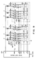
- In the foregoing embodiment, the
electrothermal transducer elements 7 are grouped into several unit blocks, and the blocks are sequentially driven. When, however, the number ofelements 7 is relatively small, as shown in Figure 10 or when the driving voltage has sufficient capacity, the simultaneous drive is possible in response to a strobe signal STB. In Figure 10, three current limiting resistors 101-1, 101-2 and 101-3 are employed. - Figure 1 shows another alternative wherein the power supply lines VH1 - VHn are provided for the respective blocks, and a common driving system is provided, wherein the divided driving operation is effected. In Figure 11, designated by a
reference 109 is a diode for preventing reverse current. - Each of the foregoing embodiments is particularly suitable to a bubble jet type recording system among various ink jet recording systems.
- It is preferable that the bubble jet recording system is based on the principle and has the structure as disclosed in U.S. Patents Nos. 4,723,129 and 4,740,796. This system is usable with a so-called ON-demand type apparatus and also with a continuous type apparatus. However, the ON-demand type is preferable because the electrothermal transducers disposed faced to the sheet or liquid passages retaining the liquid (ink) are each supplied with at least one driving signals to produce quick temperature rise beyond nuclear boiling in accordance with the recording information, by which the electrothermal transducer produces thermal energy to produce film boiling on the heating surface of the recording head, so that one bubble can be formed in the liquid corresponding to one driving signal. By the development and contraction of the bubble, the liquid (ink) is ejected through the ejection outlet to form at least one droplet. The driving signal is preferably in the form of pulses, since then the bubbles are quickly developed and contracted, and therefore, the quick response liquid (ink) ejection can be accomplished. The pulse form driving signals are preferably as disclosed in U.S. Patent Nos. 4,463,359 and 4,345,262. The temperature rise ratio of the heat applying surface is preferably as disclosed in U.S. Patent No. 4,313,124 to further improve the recording operation.
- The structure of the head may be the combination of the ejection outlet, liquid passage and the electrothermal transducer (linear liquid passage or perpendicularly bent passage) as disclosed in each of the above-mentioned U.S. Patents. Alternatively, the heating portion may be disposed at a bent portion as disclosed in U.S. Patents Nos. 4,558,333 and 4,459,660. The embodiments described in the foregoing may be used with any of such structures. In addition, the structure in which the ejecting portions are constituted by slits each of which is common to plural electrothermal transducers, as disclosed in Japanese Laid-Open Patent Application No. 123,670/1984, and the structure wherein an aperture is provided corresponding to the ejection part to absorb the pressure energy of the thermal energy, may be conveniently combined with the present embodiments.
- Furthermore, each of the foregoing embodiments is conveniently incorporated in an exchangeable chip type recording head which can be electrically connected with the main apparatus and can be supplied with the ink from the main assembly by being mounted on the main assembly. It may be conveniently incorporated in a cartridge type recording head.
- Each of the foregoing embodiments may preferably be provided with recovering means for the recording head and/or preliminary auxiliary means, since then, the advantageous effects of each of the foregoing embodiments can be further stabilized. As for those means, there are capping means for the recording head, cleaning means pressure or sucking means, preliminary heating means constituted by the electrothermal transducer and/or additional heating element, preliminary ejection mode operating means for ejecting the liquid not for the recording operation or the like.
- The recording mode of the recording apparatus may include a monochromatic recording mode (black or another main color) and in addition it may also contain at least one of a multi-color mode and a full-color mode by an integral recording head or by combination of plural recording heads. The foregoing embodiments are particularly effective for such apparatus.
- In the foregoing embodiments, the ink is described as liquid. However, it may be the ink which is solid under the room temperature or lower but is softened or liquefied under the temperature higher than the room temperature. In the ink jet recording apparatus described hereinbefore, the temperature of the ink is maintained within a range not lower than 30 °C and not higher than 70 °C, generally in order to maintain the proper viscosity of the ink for the stabilized ejection. Therefore, what is required is that the ink is or becomes liquid upon application of the signal. The ink may be such that the thermal energy is consumed for the change of phase from the solid phase to the liquid phase to prevent the temperature rise due to the thermal energy or that the ink is solidified when it is left as it is for the purpose of preventing evaporation of the ink, if the ink is liquefied by the application of thermal energy as the recording signal, and the ink is ejected as liquid. Alternatively, the ink may be such that it starts to be solidified at the point of time when it is reaches the recording material. Such ink which is liquefied by the application of the thermal energy are usable with the embodiments of the present invention. When such ink is used, the ink may be retained as liquid or solid material in the through holes or recesses of a porous sheet material, and the sheet material is faced to the electrothermal transducers. The foregoing embodiments are particularly suitable for the film boiling type recording apparatus using each of the ink materials. However, ink ejection energy producing means is not limited to the above-described electrothermal transducer, but it may be electro-mechanical transducer such as a piezoelectric element or the like, or it may be in the form of electromagnetic wave such as laser which is applied to the liquid and absorbed thereby to produce the heat which is contributable to eject the ink.
- As described in the foregoing, according to the embodiments of the present invention, each of the electrothermal transducer elements corresponding to the ejection outlets can be selectively driven for the preliminary heating or for the liquid ejection in accordance with the input data, and therefore, the temperatures of the ejection outlets are made uniform, and the high quality recording is possible with simple structure. In addition, the intervals of the ejection recovery operations can be extended, and therefore, a high speed recording operation is possible.
- Thus, according to the present invention, the ink jet recording head, a driving method for the same and the ink jet recording apparatus which can record with high recording quality, can be provided.
- While the invention has been described with reference to the structures disclosed herein, it is not confined to the details set forth and this application is intended to cover such modifications or changes as may come within the purposes of the improvements or the scope of the following claims.
- A recording method for making record on a recording material by ejection of ink, wherein after electric power enough to eject the ink for the recording on the recording material is supplied to recording device to effect the recording in a predetermined region, electric power not enough to eject the ink is supplied to the recording device.
Claims (27)
recording means for ejecting the ink to make the record on the recording material;
conveying means for conveying the recording material;
control means for applying electric power not enough to eject the ink to the recording means after applying electric power enough to eject the ink to the recording means to make the record in a predetermined region.
recording means for ejecting ink to make the record on the recording material;
conveying means for conveying the recording material;
control means for applying, after making the record in a predetermined region by ejection of the ink from said recording means, electric power not enough to eject the ink to said recording means using data provided by reversing data for said record.
a recording head having a plurality of electrothermal transducer elements for producing thermal energy contributable to ejection of ink;
ejection drive means for ejecting the ink by applying a drive signal to the electrothermal transducer elements of the recording head in accordance with data to be recorded; and
heating driving means for applying a heating driving signal not enough to eject the ink to the electrothermal transducer elements after each predetermined unit of ejection drive operations by said ejection driving means, to effect heating operation.
plural electrothermal transducer elements for generating thermal energy contributable to ejection of ink;
driving means having plural parallel current limiting elements connected to each of said electrothermal transducer elements, for selecting one or more of current limiting elements to supply to the electrothermal transducer elements electric energy enough to eject the ink or one or more current limiting elements to supply to the electrothermal transducer element electric energy not enough to eject the ink.
plural electrothermal transducer elements for generating thermal energy contributable to ejection of ink;
driving means having plural parallel current limiting elements connected to each of said electrothermal transducer elements, for selecting one or more of current limiting elements to supply to the electrothermal transducer elements electric energy enough to eject time ink or one or more current limiting elements to supply to the electrothermal transducer element electric energy not enough to eject the ink.
an ink jet recording head having outlets for discharging the inks and a plurality of electrothermal transducer elements for generating thermal energy contributable to discharge the ink, and electrothermal transducer elements being provided for the outlets, respectively; and
driving means having plural parallel current limiting elements connected to each of said electrothermal transducer elements, for selecting one or more of current limiting elements to supply to the electrothermal transducer elements electric energy enough to eject the ink or one or more current limiting elements to supply to the electrothermal transducer element electric energy not enough to eject the ink.
Applications Claiming Priority (6)
| Application Number | Priority Date | Filing Date | Title |
|---|---|---|---|
| JP8230589 | 1989-03-31 | ||
| JP8231189 | 1989-03-31 | ||
| JP82305/89 | 1989-03-31 | ||
| JP82311/89 | 1989-03-31 | ||
| JP75470/90 | 1990-03-27 | ||
| JP2075470A JP2705994B2 (en) | 1989-03-31 | 1990-03-27 | Recording method, recording apparatus, and recording head |
Publications (3)
| Publication Number | Publication Date |
|---|---|
| EP0390202A2 true EP0390202A2 (en) | 1990-10-03 |
| EP0390202A3 EP0390202A3 (en) | 1991-02-20 |
| EP0390202B1 EP0390202B1 (en) | 1995-06-28 |
Family
ID=27301838
Family Applications (1)
| Application Number | Title | Priority Date | Filing Date |
|---|---|---|---|
| EP90106174A Expired - Lifetime EP0390202B1 (en) | 1989-03-31 | 1990-03-30 | Ink jet recording head, driving method for same and ink jet recording apparatus |
Country Status (4)
| Country | Link |
|---|---|
| US (1) | US5172134A (en) |
| EP (1) | EP0390202B1 (en) |
| AT (1) | ATE124330T1 (en) |
| DE (1) | DE69020397T2 (en) |
Cited By (20)
| Publication number | Priority date | Publication date | Assignee | Title |
|---|---|---|---|---|
| EP0440469A2 (en) * | 1990-02-02 | 1991-08-07 | Canon Kabushiki Kaisha | Ink jet recording apparatus and ink jet recording head |
| EP0461936A2 (en) * | 1990-06-15 | 1991-12-18 | Canon Kabushiki Kaisha | Driving method for ink jet head |
| EP0526223A2 (en) * | 1991-08-01 | 1993-02-03 | Canon Kabushiki Kaisha | Ink jet recording apparatus |
| EP0650836A2 (en) * | 1993-10-27 | 1995-05-03 | Hewlett-Packard Company | Temperature control of thermal ink-jet print heads by using synchronous non-nucleating pulses |
| US5475405A (en) * | 1993-12-14 | 1995-12-12 | Hewlett-Packard Company | Control circuit for regulating temperature in an ink-jet print head |
| EP0694405A3 (en) * | 1991-01-18 | 1996-04-03 | Canon Kk | Ink jet recording method and apparatus using thermal energy |
| EP0709196A3 (en) * | 1994-10-27 | 1996-09-04 | Canon Kk | Print head, and print method and apparatus using the same |
| EP0690411A3 (en) * | 1994-06-30 | 1996-10-16 | Canon Kk | Printhead, printing apparatus and printing method using printhead |
| WO1997035167A2 (en) * | 1996-03-15 | 1997-09-25 | Xaar Technology Limited | Operation of droplet deposition apparatus |
| US5736995A (en) * | 1991-05-01 | 1998-04-07 | Hewlett-Packard Company | Temperature control of thermal inkjet printheads by using synchronous non-nucleating pulses |
| US5861895A (en) * | 1991-01-09 | 1999-01-19 | Canon Kabushiki Kaisha | Ink jet recording method and apparatus controlling driving signals in accordance with head temperature |
| EP0900657A3 (en) * | 1997-09-08 | 1999-06-09 | Konica Corporation | Ink jet printer |
| US5992963A (en) * | 1994-09-09 | 1999-11-30 | Canon Kabushiki Kaisha | Printing apparatus and method for controlling the temperature of a printing head with heating and cooling devices |
| WO2002004219A1 (en) * | 2000-06-30 | 2002-01-17 | Silverbrook Research Pty Ltd | Controlling the timing of printhead nozzle firing |
| US6687022B1 (en) | 1998-11-09 | 2004-02-03 | Silverbrook Research Pty Ltd | Multiple simultaneous access |
| US6747760B2 (en) | 2000-05-23 | 2004-06-08 | Silverbrook Research Pty Ltd | Print engine controller for a multi-segment printhead |
| EP2361769A3 (en) * | 2010-02-26 | 2012-02-29 | Palo Alto Research Center Incorporated | Apparatus for controlled freezing of melted solid ink in a solid ink printer |
| US8506063B2 (en) | 2011-02-07 | 2013-08-13 | Palo Alto Research Center Incorporated | Coordination of pressure and temperature during ink phase change |
| US8556372B2 (en) | 2011-02-07 | 2013-10-15 | Palo Alto Research Center Incorporated | Cooling rate and thermal gradient control to reduce bubbles and voids in phase change ink |
| US8562117B2 (en) | 2011-02-07 | 2013-10-22 | Palo Alto Research Center Incorporated | Pressure pulses to reduce bubbles and voids in phase change ink |
Families Citing this family (46)
| Publication number | Priority date | Publication date | Assignee | Title |
|---|---|---|---|---|
| JP2705994B2 (en) * | 1989-03-31 | 1998-01-28 | キヤノン株式会社 | Recording method, recording apparatus, and recording head |
| US5808632A (en) * | 1990-02-02 | 1998-09-15 | Canon Kabushiki Kaisha | Recording apparatus and method using ink jet recording head |
| JP2980444B2 (en) * | 1991-01-19 | 1999-11-22 | キヤノン株式会社 | Liquid ejector having bubble introduction mechanism in liquid chamber, recording apparatus and recording method using the same |
| CA2075097C (en) * | 1991-08-02 | 2000-03-28 | Hiroyuki Ishinaga | Recording apparatus, recording head and substrate therefor |
| JP2877589B2 (en) * | 1991-10-29 | 1999-03-31 | キヤノン株式会社 | Ink droplet ejection recording head and recording method thereof |
| JP3138349B2 (en) * | 1992-04-03 | 2001-02-26 | ローム株式会社 | LED printer |
| US5629724A (en) * | 1992-05-29 | 1997-05-13 | Xerox Corporation | Stabilization of the free surface of a liquid |
| JPH0671875A (en) * | 1992-06-30 | 1994-03-15 | Fuji Xerox Co Ltd | Ink-jet recorder |
| JPH0631932A (en) * | 1992-07-14 | 1994-02-08 | Fuji Xerox Co Ltd | Ink-jet recording device |
| JP3099549B2 (en) * | 1992-09-18 | 2000-10-16 | 富士ゼロックス株式会社 | Preliminary head driving method for inkjet recording apparatus |
| JP3459662B2 (en) * | 1992-12-14 | 2003-10-20 | キヤノン株式会社 | Recording device |
| US5745136A (en) * | 1993-04-16 | 1998-04-28 | Canon Kabushiki Kaishi | Liquid jet head, and liquid jet apparatus therefor |
| JPH06328722A (en) * | 1993-05-26 | 1994-11-29 | Canon Inc | Ink jet recording head and ink jet recording apparatus using the same |
| JP3391889B2 (en) | 1993-06-23 | 2003-03-31 | キヤノン株式会社 | Ink jet recording method and recording apparatus |
| JP3376036B2 (en) * | 1993-09-24 | 2003-02-10 | キヤノン株式会社 | Ink jet recording apparatus and recording method |
| SG59905A1 (en) | 1994-03-04 | 1999-02-22 | Canon Kk | An ink jet recording apparatus |
| SG52140A1 (en) * | 1994-03-04 | 1998-09-28 | Canon Kk | Ink jet recording head and method of manufacture therefor and laser processing apparatus and ink jet recording apparatus |
| SG44309A1 (en) * | 1994-03-04 | 1997-12-19 | Canon Kk | An ink jet recording apparatus |
| JP3406941B2 (en) * | 1994-08-31 | 2003-05-19 | キヤノン株式会社 | Image recording method and apparatus |
| US5969730A (en) * | 1994-11-07 | 1999-10-19 | Canon Aptex Inc. | Printer |
| JP3315574B2 (en) * | 1995-02-13 | 2002-08-19 | キヤノン株式会社 | INK JET PRINTING APPARATUS AND INK JET PRINTING METHOD |
| CA2168994C (en) * | 1995-03-08 | 2000-01-18 | Juan J. Becerra | Method and apparatus for interleaving pulses in a liquid recorder |
| JP4038598B2 (en) | 1996-03-07 | 2008-01-30 | セイコーエプソン株式会社 | Ink jet printer and driving method thereof |
| US5933161A (en) * | 1996-03-21 | 1999-08-03 | Fuji Xerox Co., Ltd. | Ink-jet recorder having a driving circuit for driving heat-generating elements |
| US6322183B1 (en) * | 1996-11-14 | 2001-11-27 | Canon Kabushiki Kaisha | Recording apparatus operated in split driving mode and method of driving recording apparatus |
| US6296350B1 (en) | 1997-03-25 | 2001-10-02 | Lexmark International, Inc. | Ink jet printer having driver circuit for generating warming and firing pulses for heating elements |
| EP0925925A3 (en) | 1997-12-26 | 2000-01-19 | Canon Kabushiki Kaisha | Method for correcting a recording head, correction apparatus therefor, recording head corrected by use of such apparatus, and recording apparatus using such recording head |
| DE69935958T2 (en) * | 1998-10-27 | 2008-01-10 | Canon K.K. | Head carrier layer, printhead with data storage and printing device |
| CA2311017C (en) * | 1999-06-14 | 2004-07-20 | Canon Kabushiki Kaisha | Recording head, substrate for use of recording head, and recording apparatus |
| US6170936B1 (en) * | 1999-07-23 | 2001-01-09 | Lexmark International, Inc. | Substrate heater circuit topology for inkjet printhead |
| TW496827B (en) * | 2000-08-04 | 2002-08-01 | Benq Corp | Driving circuit capable of maintaining heat equilibrium of a print head nozzle |
| US6601936B2 (en) * | 2000-11-14 | 2003-08-05 | Cypress Semiconductor Corp. | Real time adaptive inkjet temperature regulation controller |
| TW539621B (en) * | 2002-04-03 | 2003-07-01 | Benq Corp | Ink jet printer with independent driving circuit for preheat and heat maintance |
| US6959973B2 (en) * | 2002-07-23 | 2005-11-01 | Canon Kabushiki Kaisha | Ink jet printing apparatus and ink jet printing method using selective application of different voltages to control ink discharge |
| US7399043B2 (en) | 2002-12-02 | 2008-07-15 | Silverbrook Research Pty Ltd | Compensation for uneven printhead module lengths in a multi-module printhead |
| TWI246462B (en) * | 2003-06-10 | 2006-01-01 | Canon Kk | Ink-jet printhead substrate, driving control method, ink-jet printhead and ink-jet printing apparatus |
| US7125105B2 (en) * | 2003-09-08 | 2006-10-24 | Canon Kabushiki Kaisha | Semiconductor device for liquid ejection head, liquid ejection head, and liquid ejection apparatus |
| US7281778B2 (en) | 2004-03-15 | 2007-10-16 | Fujifilm Dimatix, Inc. | High frequency droplet ejection device and method |
| US8491076B2 (en) | 2004-03-15 | 2013-07-23 | Fujifilm Dimatix, Inc. | Fluid droplet ejection devices and methods |
| US7204585B2 (en) * | 2004-04-28 | 2007-04-17 | Hewlett-Packard Development Company, L.P. | Method and system for improving printer performance |
| US8708441B2 (en) | 2004-12-30 | 2014-04-29 | Fujifilm Dimatix, Inc. | Ink jet printing |
| US20070024652A1 (en) * | 2005-07-29 | 2007-02-01 | Lexmark International, Inc. | Method and apparatus for printing |
| EP2065197B1 (en) * | 2006-09-20 | 2017-03-01 | Konica Minolta Holdings, Inc. | Ink jet head driving apparatus |
| US7988247B2 (en) | 2007-01-11 | 2011-08-02 | Fujifilm Dimatix, Inc. | Ejection of drops having variable drop size from an ink jet printer |
| US8393702B2 (en) | 2009-12-10 | 2013-03-12 | Fujifilm Corporation | Separation of drive pulses for fluid ejector |
| US8864276B2 (en) | 2010-05-10 | 2014-10-21 | Canon Kabushiki Kaisha | Printhead and printing apparatus utilizing data signal transfer error detection |
Citations (3)
| Publication number | Priority date | Publication date | Assignee | Title |
|---|---|---|---|---|
| DE3311735A1 (en) * | 1982-04-02 | 1983-10-06 | Canon Kk | INK-JET PRINTER |
| US4463359A (en) * | 1979-04-02 | 1984-07-31 | Canon Kabushiki Kaisha | Droplet generating method and apparatus thereof |
| US4791435A (en) * | 1987-07-23 | 1988-12-13 | Hewlett-Packard Company | Thermal inkjet printhead temperature control |
Family Cites Families (15)
| Publication number | Priority date | Publication date | Assignee | Title |
|---|---|---|---|---|
| CA1127227A (en) * | 1977-10-03 | 1982-07-06 | Ichiro Endo | Liquid jet recording process and apparatus therefor |
| US4296421A (en) * | 1978-10-26 | 1981-10-20 | Canon Kabushiki Kaisha | Ink jet recording device using thermal propulsion and mechanical pressure changes |
| US4330787A (en) * | 1978-10-31 | 1982-05-18 | Canon Kabushiki Kaisha | Liquid jet recording device |
| US4345262A (en) * | 1979-02-19 | 1982-08-17 | Canon Kabushiki Kaisha | Ink jet recording method |
| US4313124A (en) * | 1979-05-18 | 1982-01-26 | Canon Kabushiki Kaisha | Liquid jet recording process and liquid jet recording head |
| US4558333A (en) * | 1981-07-09 | 1985-12-10 | Canon Kabushiki Kaisha | Liquid jet recording head |
| JPS58220757A (en) * | 1982-06-18 | 1983-12-22 | Canon Inc | Liquid jet recording head |
| JPS59123670A (en) * | 1982-12-28 | 1984-07-17 | Canon Inc | Ink jet head |
| JPH0679853B2 (en) * | 1983-12-09 | 1994-10-12 | キヤノン株式会社 | Liquid ejector |
| JPS60219060A (en) * | 1984-04-17 | 1985-11-01 | Canon Inc | Liquid injection recorder |
| JPS60248357A (en) * | 1984-05-25 | 1985-12-09 | Canon Inc | Fluid jet recording device |
| GB2169855B (en) * | 1984-12-21 | 1989-11-08 | Canon Kk | Liquid-discharge recording apparatus and method of operation thereof |
| GB2169856B (en) * | 1984-12-28 | 1989-10-25 | Canon Kk | Liquid-discharge recording apparatus and a method of operation thereof |
| JPS62178349A (en) * | 1986-01-31 | 1987-08-05 | Toshiba Corp | Recorder |
| US4788563A (en) * | 1986-05-19 | 1988-11-29 | Canon Kabushiki Kaisha | Recording apparatus |
-
1990
- 1990-03-29 US US07/501,153 patent/US5172134A/en not_active Expired - Lifetime
- 1990-03-30 AT AT90106174T patent/ATE124330T1/en not_active IP Right Cessation
- 1990-03-30 DE DE69020397T patent/DE69020397T2/en not_active Expired - Fee Related
- 1990-03-30 EP EP90106174A patent/EP0390202B1/en not_active Expired - Lifetime
Patent Citations (3)
| Publication number | Priority date | Publication date | Assignee | Title |
|---|---|---|---|---|
| US4463359A (en) * | 1979-04-02 | 1984-07-31 | Canon Kabushiki Kaisha | Droplet generating method and apparatus thereof |
| DE3311735A1 (en) * | 1982-04-02 | 1983-10-06 | Canon Kk | INK-JET PRINTER |
| US4791435A (en) * | 1987-07-23 | 1988-12-13 | Hewlett-Packard Company | Thermal inkjet printhead temperature control |
Cited By (120)
| Publication number | Priority date | Publication date | Assignee | Title |
|---|---|---|---|---|
| EP0440469A2 (en) * | 1990-02-02 | 1991-08-07 | Canon Kabushiki Kaisha | Ink jet recording apparatus and ink jet recording head |
| EP0440469A3 (en) * | 1990-02-02 | 1991-09-18 | Canon Kabushiki Kaisha | Ink jet recording apparatus and ink jet recording head |
| US5343227A (en) * | 1990-02-02 | 1994-08-30 | Canon Kabushiki Kaisha | Ink jet recording apparatus and ink jet recording head with means reducing the amount of warp |
| EP0461936A3 (en) * | 1990-06-15 | 1992-07-29 | Canon Kabushiki Kaisha | Driving method for ink jet head |
| EP0461936A2 (en) * | 1990-06-15 | 1991-12-18 | Canon Kabushiki Kaisha | Driving method for ink jet head |
| US5798772A (en) * | 1990-06-15 | 1998-08-25 | Canon Kabushiki Kaisha | Driving method ink jet head |
| US5861895A (en) * | 1991-01-09 | 1999-01-19 | Canon Kabushiki Kaisha | Ink jet recording method and apparatus controlling driving signals in accordance with head temperature |
| US6457794B1 (en) | 1991-01-18 | 2002-10-01 | Canon Kabushiki Kaisha | Ink jet recording method and apparatus for controlling recording signal parameters |
| US6310636B1 (en) | 1991-01-18 | 2001-10-30 | Canon Kabushiki Kaisha | Ink jet recording method and apparatus for driving recording head based on head temperature |
| US6116710A (en) * | 1991-01-18 | 2000-09-12 | Canon Kabushiki Kaisha | Ink jet recording method and apparatus using thermal energy |
| EP0694405A3 (en) * | 1991-01-18 | 1996-04-03 | Canon Kk | Ink jet recording method and apparatus using thermal energy |
| EP0686506A3 (en) * | 1991-01-18 | 1996-04-03 | Canon Kk | Ink jet recording method and apparatus using thermal energy |
| EP0694406A3 (en) * | 1991-01-18 | 1996-04-03 | Canon Kk | Ink jet recording method and apparatus using thermal energy |
| US5894314A (en) * | 1991-01-18 | 1999-04-13 | Canon Kabushiki Kaisha | Ink jet recording apparatus using thermal energy |
| US5736995A (en) * | 1991-05-01 | 1998-04-07 | Hewlett-Packard Company | Temperature control of thermal inkjet printheads by using synchronous non-nucleating pulses |
| EP0838333A3 (en) * | 1991-08-01 | 1998-07-01 | Canon Kabushiki Kaisha | Ink jet recording apparatus having temperature control function |
| US6116709A (en) * | 1991-08-01 | 2000-09-12 | Canon Kabushiki Kaisha | Ink jet recording apparatus with temperature calculation based on prestored temperature data |
| EP0526223A2 (en) * | 1991-08-01 | 1993-02-03 | Canon Kabushiki Kaisha | Ink jet recording apparatus |
| US5745132A (en) * | 1991-08-01 | 1998-04-28 | Canon Kabushiki Kaisha | Ink jet recording apparatus having temperature control function |
| EP0838332A2 (en) * | 1991-08-01 | 1998-04-29 | Canon Kabushiki Kaisha | Ink jet recording apparatus having temperature control function |
| EP0838333A2 (en) * | 1991-08-01 | 1998-04-29 | Canon Kabushiki Kaisha | Ink jet recording apparatus having temperature control function |
| US5751304A (en) * | 1991-08-01 | 1998-05-12 | Canon Kabushiki Kaisha | Ink jet recording having temperature control function |
| EP0526223A3 (en) * | 1991-08-01 | 1993-06-23 | Canon Kabushiki Kaisha | Ink jet recording apparatus |
| EP0838334A3 (en) * | 1991-08-01 | 1998-07-01 | Canon Kabushiki Kaisha | Ink jet recording apparatus having temperature control function |
| EP0838332A3 (en) * | 1991-08-01 | 1998-07-01 | Canon Kabushiki Kaisha | Ink jet recording apparatus having temperature control function |
| US6193344B1 (en) | 1991-08-01 | 2001-02-27 | Canon Kabushiki Kaisha | Ink jet recording apparatus having temperature control function |
| US6139125A (en) * | 1991-08-01 | 2000-10-31 | Canon Kabushiki Kaisha | Ink jet recording apparatus having temperature control function |
| EP0650836A2 (en) * | 1993-10-27 | 1995-05-03 | Hewlett-Packard Company | Temperature control of thermal ink-jet print heads by using synchronous non-nucleating pulses |
| EP0650836A3 (en) * | 1993-10-27 | 1997-03-12 | Hewlett Packard Co | Temperature control of thermal ink-jet print heads by using synchronous non-nucleating pulses. |
| US5475405A (en) * | 1993-12-14 | 1995-12-12 | Hewlett-Packard Company | Control circuit for regulating temperature in an ink-jet print head |
| US5877784A (en) * | 1994-06-30 | 1999-03-02 | Canon Kabushiki Kaisha | Printhead, printing apparatus and printing method using printhead |
| CN1092569C (en) * | 1994-06-30 | 2002-10-16 | 佳能株式会社 | Printhead, printing apparatus and printing method using printhead |
| EP0690411A3 (en) * | 1994-06-30 | 1996-10-16 | Canon Kk | Printhead, printing apparatus and printing method using printhead |
| US5992963A (en) * | 1994-09-09 | 1999-11-30 | Canon Kabushiki Kaisha | Printing apparatus and method for controlling the temperature of a printing head with heating and cooling devices |
| EP0709196A3 (en) * | 1994-10-27 | 1996-09-04 | Canon Kk | Print head, and print method and apparatus using the same |
| US5867200A (en) * | 1994-10-27 | 1999-02-02 | Canon Kabushiki Kaisha | Print head, and print pre-heat method and apparatus using the same |
| EP1213145A3 (en) * | 1996-03-15 | 2002-07-24 | Xaar Technology Limited | Operation of droplet deposition apparatus |
| WO1997035167A3 (en) * | 1996-03-15 | 1997-12-04 | Operation of droplet deposition apparatus | |
| US6629740B2 (en) | 1996-03-15 | 2003-10-07 | Xaar Technology Limited | Operation of droplet deposition apparatus |
| KR100482792B1 (en) * | 1996-03-15 | 2005-09-16 | 자아 테크날러쥐 리미티드 | Operation of droplet deposition apparatus |
| WO1997035167A2 (en) * | 1996-03-15 | 1997-09-25 | Xaar Technology Limited | Operation of droplet deposition apparatus |
| US6568779B1 (en) | 1996-03-15 | 2003-05-27 | Xaar Technology Limited | Operation of droplet deposition apparatus |
| US6270180B1 (en) | 1997-09-08 | 2001-08-07 | Konica Corporation | Ink jet printer |
| EP0900657A3 (en) * | 1997-09-08 | 1999-06-09 | Konica Corporation | Ink jet printer |
| US7092125B2 (en) | 1998-11-09 | 2006-08-15 | Silverbrook Research Pty Ltd | Method of printing using PC and printer |
| US7284805B2 (en) | 1998-11-09 | 2007-10-23 | Silverbrook Research Pty Ltd | Edge delta runlength (EDRL) data stream decoder for bi-level graphics |
| US7976153B2 (en) | 1998-11-09 | 2011-07-12 | Silverbrook Research Pty Ltd | Inkjet printer with retractable cover serving as media guide |
| US6843545B2 (en) | 1998-11-09 | 2005-01-18 | Silverbrook Research Pty Ltd | Determining the volume of ink in a printer reservoir |
| US6851782B2 (en) | 1998-11-09 | 2005-02-08 | Silverbrook Research Pty Ltd | Method of and apparatus for adjusting the duration of printing pulses |
| US6877834B2 (en) | 1998-11-09 | 2005-04-12 | Silverbrook Research Pty Ltd | Printer ink capping mechanism |
| US7971950B2 (en) | 1998-11-09 | 2011-07-05 | Silverbrook Research Pty Ltd | Method of controlling printhead |
| US6969139B2 (en) | 1998-11-09 | 2005-11-29 | Silverbrook Research Pty Ltd | Drop size control for a printer |
| US7025434B2 (en) | 1998-11-09 | 2006-04-11 | Silverbrook Research Pty Ltd | Half toner and compositor circuit for a printer |
| US7059695B2 (en) | 1998-11-09 | 2006-06-13 | Silverbrook Research Pty Ltd | Print engine for a pagewidth inkjet printer |
| US7064867B2 (en) | 1998-11-09 | 2006-06-20 | Silverbrook Research Pty Ltd | Graphics imaging method |
| US7065247B2 (en) | 1998-11-09 | 2006-06-20 | Silverbrook Research Pty Ltd | Apparatus for and method of graphics imaging |
| US7070251B2 (en) | 1998-11-09 | 2006-07-04 | Silverbrook Research Pty Ltd | Method of adjusting the duration of printing pulses |
| US7072076B2 (en) | 1998-11-09 | 2006-07-04 | Silverbrook Research Pty Ltd | Printing method using PC rendering |
| US7079286B2 (en) | 1998-11-09 | 2006-07-18 | Silverbrook Research Pty Ltd | Method of graphics imaging |
| US7077494B2 (en) | 1998-11-09 | 2006-07-18 | Silverbrook Research Pty Ltd | Printer having a fluid capping mechanism |
| US7936478B2 (en) | 1998-11-09 | 2011-05-03 | Silverbrook Research Pty Ltd | Method of printing a compressed image having a bi-level black layer and a contone layer |
| US7108346B2 (en) | 1998-11-09 | 2006-09-19 | Silverbrook Research Pty Ltd | Pagewidth printer having a printer controller with page expansion and control circuitry |
| US7118186B2 (en) | 1998-11-09 | 2006-10-10 | Silverbrook Research Pty Ltd | Inkjet printhead feedback processing arrangement |
| US7128384B2 (en) | 1998-11-09 | 2006-10-31 | Kia Silverbrook | Printer controller with printhead feedback |
| US7136195B2 (en) | 1998-11-09 | 2006-11-14 | Silverbrook Research Pty Ltd | Fluid capping mechanism |
| US7154637B2 (en) | 1998-11-09 | 2006-12-26 | Silverbrook Research Pty Ltd | Dither volume for cell location |
| US7164501B2 (en) | 1998-11-09 | 2007-01-16 | Silverbrook Research Pty Ltd | Printer controller integrated circuit |
| US7164505B2 (en) | 1998-11-09 | 2007-01-16 | Silverbrook Research Pty Ltd | Edge delta runlength expander unit for bi-level graphics |
| US7177052B2 (en) | 1998-11-09 | 2007-02-13 | Silverbrook Research Pty Ltd | Dithered image for bi-level printing |
| US7187468B2 (en) | 1998-11-09 | 2007-03-06 | Silverbrook Research Pty Ltd | Method for ensuring consistent dot size in an inkjet printhead |
| US7188921B2 (en) | 1998-11-09 | 2007-03-13 | Silverbrook Research Pty Ltd | Generation of print data |
| US7193743B2 (en) | 1998-11-09 | 2007-03-20 | Silverbrook Research Pty Ltd | Printer driver software product with edge runlength encoder |
| US7196814B2 (en) | 1998-11-09 | 2007-03-27 | Silverbrook Res Pty Ltd | Inkjet printer printhead interface circuit |
| US7206098B2 (en) | 1998-11-09 | 2007-04-17 | Silverbrook Research Pty Ltd | Method for avoiding print buffer underrun |
| US7215443B2 (en) | 1998-11-09 | 2007-05-08 | Silverbrook Research Pty Ltd | Method of and apparatus for printing |
| US7265877B2 (en) | 1998-11-09 | 2007-09-04 | Silverbrook Research Pty Ltd | Printer including firmware to check page description data format |
| US7265869B2 (en) | 1998-11-09 | 2007-09-04 | Silverbrook Research Pty Ltd | Compact printer housing |
| US7270394B2 (en) | 1998-11-09 | 2007-09-18 | Silverbrook Research Pty Ltd | Printhead cartridge having coupled media transport and capping mechanisms |
| US7277205B2 (en) | 1998-11-09 | 2007-10-02 | Silverbrook Research Pty Ltd | Dither volume with three thresholds for each cell location |
| US7283280B2 (en) | 1998-11-09 | 2007-10-16 | Silverbrook Research Pty Ltd | Ink temperature control for multiprinthead printer |
| US7283281B2 (en) | 1998-11-09 | 2007-10-16 | Silverbrook Research Pty Ltd | Processor circuitry for a pagewidth printhead |
| US6687022B1 (en) | 1998-11-09 | 2004-02-03 | Silverbrook Research Pty Ltd | Multiple simultaneous access |
| US7298519B2 (en) | 1998-11-09 | 2007-11-20 | Silverbrook Research Pty Ltd | Data register arrangement for an inkjet printer |
| US7306307B2 (en) | 1998-11-09 | 2007-12-11 | Silverbrook Research Pty Ltd | Processing apparatus for an inkjet printer |
| US7333235B2 (en) | 1998-11-09 | 2008-02-19 | Silverbrook Research Pty Ltd | Printer controller for controlling operation of a pagewidth printhead |
| US7349125B2 (en) | 1998-11-09 | 2008-03-25 | Silverbrook Research Pty Ltd | Application specific integrated circuit (ASIC) in the form of a printer processor |
| US7365874B2 (en) | 1998-11-09 | 2008-04-29 | Silverbrook Research Pty Ltd | Printer for authenticating a replaceable ink cartridge |
| US7372593B2 (en) | 1998-11-09 | 2008-05-13 | Silverbrook Research Pty Ltd | Inkjet printhead capping mechanism |
| US7391531B2 (en) | 1998-11-09 | 2008-06-24 | Silverbrook Research Pty Ltd | Printer with replaceable ink cartridge and print quality IC |
| US7400419B2 (en) | 1998-11-09 | 2008-07-15 | Silverbrook Research Pty Ltd | Inkjet printer with folding input tray |
| US7413273B2 (en) | 1998-11-09 | 2008-08-19 | Silverbrook Research Pty Ltd | Generation of print data for printing |
| US7429092B2 (en) | 1998-11-09 | 2008-09-30 | Silverbrook Research Pty Ltd | Method of printing with a personal computer and connected printer |
| US7456996B2 (en) | 1998-11-09 | 2008-11-25 | Silverbrook Research Pty Ltd | Method of processing print data incorporating obscuration detection between layers |
| US7468808B2 (en) | 1998-11-09 | 2008-12-23 | Silverbrook Research Pty Ltd | Inkjet printer with retractable support and cover |
| US7469983B2 (en) | 1998-11-09 | 2008-12-30 | Kia Silverbrook | Drop size control |
| US7537297B2 (en) | 1998-11-09 | 2009-05-26 | Silverbrook Research Pty Ltd | Printer controller for a MEMS-based page width inkjet printer |
| US7567363B2 (en) | 1998-11-09 | 2009-07-28 | Silverbrook Research Pty Ltd | Image processing method incorporating decompression |
| US7591522B2 (en) | 1998-11-09 | 2009-09-22 | Silverbrook Research Pty Ltd | Adjusting printing parameters in response to printhead feedback |
| US7639397B2 (en) | 1998-11-09 | 2009-12-29 | Silverbrook Research Pty Ltd | Page expansion and printing method incorporating halftoning and compositing |
| US7646511B2 (en) | 1998-11-09 | 2010-01-12 | Silverbrook Research Pty Ltd | Method of printing a compressed image having bi-level black contone data layers |
| US7690748B2 (en) | 1998-11-09 | 2010-04-06 | Silverbrook Research Pty Ltd | Method of printing with a personal computer and connected printer |
| US7717538B2 (en) | 1998-11-09 | 2010-05-18 | Silverbrook Research Pty Ltd | Inkjet printer with capping mechanism for printhead assembly |
| US7744181B2 (en) | 1998-11-09 | 2010-06-29 | Silverbrook Research Pty Ltd | Printer controller for monitoring an ink drop count |
| US7817306B2 (en) | 1998-11-09 | 2010-10-19 | Silverbrook Research Pty Ltd | Method of page expansion and printing with a pagewidth printer having low-speed and high-speed firing modes |
| US7847972B2 (en) | 1998-11-09 | 2010-12-07 | Silverbrook Research Pty Ltd | Paper transport mechanism with a capping mechanism |
| US7857410B2 (en) | 1998-11-09 | 2010-12-28 | Silverbrook Research Pty Ltd | Printer controller for controlling an ink dot size |
| US7864361B2 (en) | 1998-11-09 | 2011-01-04 | Silverbrook Research Pty Ltd | Inkjet printer with dual page memory and page expander |
| US7876466B2 (en) | 1998-11-09 | 2011-01-25 | Silverbrook Research Pty Ltd | Printer controller having JPEG and EDRL circuitry |
| US7876475B2 (en) | 1998-11-09 | 2011-01-25 | Silverbrook Research Pty Ltd | Printer controller for a pagewidth printhead having halftoner and compositor unit |
| US7898694B2 (en) | 1998-11-09 | 2011-03-01 | Silverbrook Research Pty Ltd | Printer controller for a pagewidth printer configured to perform ink counts |
| US7933046B2 (en) | 1998-11-09 | 2011-04-26 | Silverbrook Research Pty Ltd | Print engine controller for image processing page data |
| US7936480B2 (en) | 1998-11-09 | 2011-05-03 | Silverbrook Research Pty Ltd | Printer having a controller method of printing with low and high speed nozzle firing modes |
| US6747760B2 (en) | 2000-05-23 | 2004-06-08 | Silverbrook Research Pty Ltd | Print engine controller for a multi-segment printhead |
| WO2002004219A1 (en) * | 2000-06-30 | 2002-01-17 | Silverbrook Research Pty Ltd | Controlling the timing of printhead nozzle firing |
| US6398332B1 (en) | 2000-06-30 | 2002-06-04 | Silverbrook Research Pty Ltd | Controlling the timing of printhead nozzle firing |
| EP2361769A3 (en) * | 2010-02-26 | 2012-02-29 | Palo Alto Research Center Incorporated | Apparatus for controlled freezing of melted solid ink in a solid ink printer |
| US8419157B2 (en) | 2010-02-26 | 2013-04-16 | Palo Alto Research Center Incorporated | Apparatus for controlled freezing of melted solid ink in a solid ink printer |
| US8506063B2 (en) | 2011-02-07 | 2013-08-13 | Palo Alto Research Center Incorporated | Coordination of pressure and temperature during ink phase change |
| US8556372B2 (en) | 2011-02-07 | 2013-10-15 | Palo Alto Research Center Incorporated | Cooling rate and thermal gradient control to reduce bubbles and voids in phase change ink |
| US8562117B2 (en) | 2011-02-07 | 2013-10-22 | Palo Alto Research Center Incorporated | Pressure pulses to reduce bubbles and voids in phase change ink |
Also Published As
| Publication number | Publication date |
|---|---|
| ATE124330T1 (en) | 1995-07-15 |
| EP0390202B1 (en) | 1995-06-28 |
| EP0390202A3 (en) | 1991-02-20 |
| US5172134A (en) | 1992-12-15 |
| DE69020397T2 (en) | 1995-11-30 |
| DE69020397D1 (en) | 1995-08-03 |
Similar Documents
| Publication | Publication Date | Title |
|---|---|---|
| EP0390202B1 (en) | Ink jet recording head, driving method for same and ink jet recording apparatus | |
| US5281980A (en) | Ink jet recording head | |
| EP0842777B1 (en) | Recording head system for ink jet recording apparatus and method for driving the same | |
| EP0747221B1 (en) | Ink jet head, ink jet apparatus and ink jet recording method | |
| EP0627313B1 (en) | Ink jet recording head and ink jet recording apparatus using same | |
| EP1466736B1 (en) | Printhead substrate, printhead and printing apparatus | |
| US7588317B2 (en) | Printing apparatus, printhead, and driving method therefor | |
| EP0876917B1 (en) | Control method for ink jet recording apparatus and ink jet recording apparatus | |
| JPH07242004A (en) | Print head, manufacturing apparatus and manufacture thereof and print device | |
| EP0443801B1 (en) | Liquid discharging recording head | |
| JPH07241992A (en) | Recording head, method and device for recording with such recording head | |
| US5638100A (en) | Ink jet and ink preliminary ejecting method | |
| KR100549484B1 (en) | Printing apparatus and print control method | |
| JP4502358B2 (en) | RECORDING HEAD SUBSTRATE, RECORDING HEAD, AND RECORDING DEVICE | |
| US6276776B1 (en) | Ink-jet printer and temperature control method of recording head | |
| KR20020083477A (en) | Printing apparatus and printing control method | |
| JPH03227643A (en) | Ink jet recorder | |
| JPH03277553A (en) | Method and device for recording | |
| JP4780882B2 (en) | Inkjet recording apparatus and inkjet recording method | |
| JPH03234629A (en) | Image recording device | |
| JP3159897B2 (en) | Recording device and recording method | |
| JPH1044411A (en) | Heat insulating control device of ink jet printing head, ink jet printing head, and ink jet printer | |
| JPH03227637A (en) | Liquid jet recording head and ink jet recorder using the head | |
| JP4455013B2 (en) | Recording head driving method, recording head, and recording apparatus | |
| JP2752492B2 (en) | Recording device |
Legal Events
| Date | Code | Title | Description |
|---|---|---|---|
| PUAI | Public reference made under article 153(3) epc to a published international application that has entered the european phase |
Free format text: ORIGINAL CODE: 0009012 |
|
| 17P | Request for examination filed |
Effective date: 19900330 |
|
| AK | Designated contracting states |
Kind code of ref document: A2 Designated state(s): AT BE CH DE DK ES FR GB GR IT LI LU NL SE |
|
| PUAL | Search report despatched |
Free format text: ORIGINAL CODE: 0009013 |
|
| AK | Designated contracting states |
Kind code of ref document: A3 Designated state(s): AT BE CH DE DK ES FR GB GR IT LI LU NL SE |
|
| 17Q | First examination report despatched |
Effective date: 19930315 |
|
| GRAA | (expected) grant |
Free format text: ORIGINAL CODE: 0009210 |
|
| AK | Designated contracting states |
Kind code of ref document: B1 Designated state(s): AT BE CH DE DK ES FR GB GR IT LI LU NL SE |
|
| PG25 | Lapsed in a contracting state [announced via postgrant information from national office to epo] |
Ref country code: AT Effective date: 19950628 Ref country code: ES Free format text: THE PATENT HAS BEEN ANNULLED BY A DECISION OF A NATIONAL AUTHORITY Effective date: 19950628 Ref country code: BE Effective date: 19950628 Ref country code: NL Free format text: LAPSE BECAUSE OF FAILURE TO SUBMIT A TRANSLATION OF THE DESCRIPTION OR TO PAY THE FEE WITHIN THE PRESCRIBED TIME-LIMIT Effective date: 19950628 Ref country code: LI Effective date: 19950628 Ref country code: GR Free format text: LAPSE BECAUSE OF FAILURE TO SUBMIT A TRANSLATION OF THE DESCRIPTION OR TO PAY THE FEE WITHIN THE PRESCRIBED TIME-LIMIT Effective date: 19950628 Ref country code: CH Effective date: 19950628 Ref country code: DK Effective date: 19950628 |
|
| REF | Corresponds to: |
Ref document number: 124330 Country of ref document: AT Date of ref document: 19950715 Kind code of ref document: T |
|
| REF | Corresponds to: |
Ref document number: 69020397 Country of ref document: DE Date of ref document: 19950803 |
|
| ET | Fr: translation filed | ||
| ITF | It: translation for a ep patent filed |
Owner name: SOCIETA' ITALIANA BREVETTI S.P.A. |
|
| PG25 | Lapsed in a contracting state [announced via postgrant information from national office to epo] |
Ref country code: SE Effective date: 19950928 |
|
| REG | Reference to a national code |
Ref country code: CH Ref legal event code: PL |
|
| NLV1 | Nl: lapsed or annulled due to failure to fulfill the requirements of art. 29p and 29m of the patents act | ||
| PG25 | Lapsed in a contracting state [announced via postgrant information from national office to epo] |
Ref country code: LU Free format text: LAPSE BECAUSE OF NON-PAYMENT OF DUE FEES Effective date: 19960331 |
|
| PLBE | No opposition filed within time limit |
Free format text: ORIGINAL CODE: 0009261 |
|
| STAA | Information on the status of an ep patent application or granted ep patent |
Free format text: STATUS: NO OPPOSITION FILED WITHIN TIME LIMIT |
|
| 26N | No opposition filed | ||
| REG | Reference to a national code |
Ref country code: GB Ref legal event code: IF02 |
|
| PGFP | Annual fee paid to national office [announced via postgrant information from national office to epo] |
Ref country code: GB Payment date: 20080326 Year of fee payment: 19 Ref country code: IT Payment date: 20080320 Year of fee payment: 19 |
|
| PGFP | Annual fee paid to national office [announced via postgrant information from national office to epo] |
Ref country code: DE Payment date: 20080331 Year of fee payment: 19 |
|
| PGFP | Annual fee paid to national office [announced via postgrant information from national office to epo] |
Ref country code: FR Payment date: 20080321 Year of fee payment: 19 |
|
| GBPC | Gb: european patent ceased through non-payment of renewal fee |
Effective date: 20090330 |
|
| REG | Reference to a national code |
Ref country code: FR Ref legal event code: ST Effective date: 20091130 |
|
| PG25 | Lapsed in a contracting state [announced via postgrant information from national office to epo] |
Ref country code: DE Free format text: LAPSE BECAUSE OF NON-PAYMENT OF DUE FEES Effective date: 20091001 |
|
| PG25 | Lapsed in a contracting state [announced via postgrant information from national office to epo] |
Ref country code: FR Free format text: LAPSE BECAUSE OF NON-PAYMENT OF DUE FEES Effective date: 20091123 Ref country code: GB Free format text: LAPSE BECAUSE OF NON-PAYMENT OF DUE FEES Effective date: 20090330 |
|
| PG25 | Lapsed in a contracting state [announced via postgrant information from national office to epo] |
Ref country code: IT Free format text: LAPSE BECAUSE OF NON-PAYMENT OF DUE FEES Effective date: 20090330 |