EP0392411B2 - A control apparatus for automobiles - Google Patents
A control apparatus for automobiles Download PDFInfo
- Publication number
- EP0392411B2 EP0392411B2 EP90106737A EP90106737A EP0392411B2 EP 0392411 B2 EP0392411 B2 EP 0392411B2 EP 90106737 A EP90106737 A EP 90106737A EP 90106737 A EP90106737 A EP 90106737A EP 0392411 B2 EP0392411 B2 EP 0392411B2
- Authority
- EP
- European Patent Office
- Prior art keywords
- unit
- recording medium
- automobile
- system manager
- units
- Prior art date
- Legal status (The legal status is an assumption and is not a legal conclusion. Google has not performed a legal analysis and makes no representation as to the accuracy of the status listed.)
- Expired - Lifetime
Links
Images


Classifications
-
- B—PERFORMING OPERATIONS; TRANSPORTING
- B60—VEHICLES IN GENERAL
- B60R—VEHICLES, VEHICLE FITTINGS, OR VEHICLE PARTS, NOT OTHERWISE PROVIDED FOR
- B60R25/00—Fittings or systems for preventing or indicating unauthorised use or theft of vehicles
- B60R25/20—Means to switch the anti-theft system on or off
- B60R25/24—Means to switch the anti-theft system on or off using electronic identifiers containing a code not memorised by the user
-
- B—PERFORMING OPERATIONS; TRANSPORTING
- B60—VEHICLES IN GENERAL
- B60R—VEHICLES, VEHICLE FITTINGS, OR VEHICLE PARTS, NOT OTHERWISE PROVIDED FOR
- B60R25/00—Fittings or systems for preventing or indicating unauthorised use or theft of vehicles
- B60R25/01—Fittings or systems for preventing or indicating unauthorised use or theft of vehicles operating on vehicle systems or fittings, e.g. on doors, seats or windscreens
- B60R25/04—Fittings or systems for preventing or indicating unauthorised use or theft of vehicles operating on vehicle systems or fittings, e.g. on doors, seats or windscreens operating on the propulsion system, e.g. engine or drive motor
-
- B—PERFORMING OPERATIONS; TRANSPORTING
- B60—VEHICLES IN GENERAL
- B60R—VEHICLES, VEHICLE FITTINGS, OR VEHICLE PARTS, NOT OTHERWISE PROVIDED FOR
- B60R25/00—Fittings or systems for preventing or indicating unauthorised use or theft of vehicles
- B60R25/10—Fittings or systems for preventing or indicating unauthorised use or theft of vehicles actuating a signalling device
-
- G—PHYSICS
- G05—CONTROLLING; REGULATING
- G05B—CONTROL OR REGULATING SYSTEMS IN GENERAL; FUNCTIONAL ELEMENTS OF SUCH SYSTEMS; MONITORING OR TESTING ARRANGEMENTS FOR SUCH SYSTEMS OR ELEMENTS
- G05B19/00—Programme-control systems
- G05B19/02—Programme-control systems electric
- G05B19/04—Programme control other than numerical control, i.e. in sequence controllers or logic controllers
- G05B19/042—Programme control other than numerical control, i.e. in sequence controllers or logic controllers using digital processors
- G05B19/0428—Safety, monitoring
-
- G—PHYSICS
- G07—CHECKING-DEVICES
- G07C—TIME OR ATTENDANCE REGISTERS; REGISTERING OR INDICATING THE WORKING OF MACHINES; GENERATING RANDOM NUMBERS; VOTING OR LOTTERY APPARATUS; ARRANGEMENTS, SYSTEMS OR APPARATUS FOR CHECKING NOT PROVIDED FOR ELSEWHERE
- G07C5/00—Registering or indicating the working of vehicles
- G07C5/08—Registering or indicating performance data other than driving, working, idle, or waiting time, with or without registering driving, working, idle or waiting time
- G07C5/0841—Registering performance data
- G07C5/085—Registering performance data using electronic data carriers
- G07C5/0858—Registering performance data using electronic data carriers wherein the data carrier is removable
-
- G—PHYSICS
- G07—CHECKING-DEVICES
- G07C—TIME OR ATTENDANCE REGISTERS; REGISTERING OR INDICATING THE WORKING OF MACHINES; GENERATING RANDOM NUMBERS; VOTING OR LOTTERY APPARATUS; ARRANGEMENTS, SYSTEMS OR APPARATUS FOR CHECKING NOT PROVIDED FOR ELSEWHERE
- G07C9/00—Individual registration on entry or exit
- G07C9/20—Individual registration on entry or exit involving the use of a pass
- G07C9/22—Individual registration on entry or exit involving the use of a pass in combination with an identity check of the pass holder
-
- B—PERFORMING OPERATIONS; TRANSPORTING
- B60—VEHICLES IN GENERAL
- B60R—VEHICLES, VEHICLE FITTINGS, OR VEHICLE PARTS, NOT OTHERWISE PROVIDED FOR
- B60R16/00—Electric or fluid circuits specially adapted for vehicles and not otherwise provided for; Arrangement of elements of electric or fluid circuits specially adapted for vehicles and not otherwise provided for
- B60R16/02—Electric or fluid circuits specially adapted for vehicles and not otherwise provided for; Arrangement of elements of electric or fluid circuits specially adapted for vehicles and not otherwise provided for electric constitutive elements
- B60R16/03—Electric or fluid circuits specially adapted for vehicles and not otherwise provided for; Arrangement of elements of electric or fluid circuits specially adapted for vehicles and not otherwise provided for electric constitutive elements for supply of electrical power to vehicle subsystems or for
- B60R16/0315—Electric or fluid circuits specially adapted for vehicles and not otherwise provided for; Arrangement of elements of electric or fluid circuits specially adapted for vehicles and not otherwise provided for electric constitutive elements for supply of electrical power to vehicle subsystems or for using multiplexing techniques
-
- G—PHYSICS
- G05—CONTROLLING; REGULATING
- G05B—CONTROL OR REGULATING SYSTEMS IN GENERAL; FUNCTIONAL ELEMENTS OF SUCH SYSTEMS; MONITORING OR TESTING ARRANGEMENTS FOR SUCH SYSTEMS OR ELEMENTS
- G05B2219/00—Program-control systems
- G05B2219/20—Pc systems
- G05B2219/23—Pc programming
- G05B2219/23355—Magnetic card
-
- G—PHYSICS
- G05—CONTROLLING; REGULATING
- G05B—CONTROL OR REGULATING SYSTEMS IN GENERAL; FUNCTIONAL ELEMENTS OF SUCH SYSTEMS; MONITORING OR TESTING ARRANGEMENTS FOR SUCH SYSTEMS OR ELEMENTS
- G05B2219/00—Program-control systems
- G05B2219/20—Pc systems
- G05B2219/23—Pc programming
- G05B2219/23362—Floppy diskette
-
- G—PHYSICS
- G05—CONTROLLING; REGULATING
- G05B—CONTROL OR REGULATING SYSTEMS IN GENERAL; FUNCTIONAL ELEMENTS OF SUCH SYSTEMS; MONITORING OR TESTING ARRANGEMENTS FOR SUCH SYSTEMS OR ELEMENTS
- G05B2219/00—Program-control systems
- G05B2219/20—Pc systems
- G05B2219/23—Pc programming
- G05B2219/23375—Function switch, knob with piezo, strain gauge
-
- G—PHYSICS
- G05—CONTROLLING; REGULATING
- G05B—CONTROL OR REGULATING SYSTEMS IN GENERAL; FUNCTIONAL ELEMENTS OF SUCH SYSTEMS; MONITORING OR TESTING ARRANGEMENTS FOR SUCH SYSTEMS OR ELEMENTS
- G05B2219/00—Program-control systems
- G05B2219/20—Pc systems
- G05B2219/24—Pc safety
- G05B2219/24098—Scan and display states of all actuators if controller fails
-
- G—PHYSICS
- G05—CONTROLLING; REGULATING
- G05B—CONTROL OR REGULATING SYSTEMS IN GENERAL; FUNCTIONAL ELEMENTS OF SUCH SYSTEMS; MONITORING OR TESTING ARRANGEMENTS FOR SUCH SYSTEMS OR ELEMENTS
- G05B2219/00—Program-control systems
- G05B2219/20—Pc systems
- G05B2219/24—Pc safety
- G05B2219/24167—Encryption, password, user access privileges
-
- G—PHYSICS
- G05—CONTROLLING; REGULATING
- G05B—CONTROL OR REGULATING SYSTEMS IN GENERAL; FUNCTIONAL ELEMENTS OF SUCH SYSTEMS; MONITORING OR TESTING ARRANGEMENTS FOR SUCH SYSTEMS OR ELEMENTS
- G05B2219/00—Program-control systems
- G05B2219/20—Pc systems
- G05B2219/25—Pc structure of the system
- G05B2219/25083—For each subsystem a configuration
-
- G—PHYSICS
- G05—CONTROLLING; REGULATING
- G05B—CONTROL OR REGULATING SYSTEMS IN GENERAL; FUNCTIONAL ELEMENTS OF SUCH SYSTEMS; MONITORING OR TESTING ARRANGEMENTS FOR SUCH SYSTEMS OR ELEMENTS
- G05B2219/00—Program-control systems
- G05B2219/20—Pc systems
- G05B2219/25—Pc structure of the system
- G05B2219/25084—Select configuration as function of operator
-
- G—PHYSICS
- G05—CONTROLLING; REGULATING
- G05B—CONTROL OR REGULATING SYSTEMS IN GENERAL; FUNCTIONAL ELEMENTS OF SUCH SYSTEMS; MONITORING OR TESTING ARRANGEMENTS FOR SUCH SYSTEMS OR ELEMENTS
- G05B2219/00—Program-control systems
- G05B2219/20—Pc systems
- G05B2219/25—Pc structure of the system
- G05B2219/25171—Serial, RS232
-
- G—PHYSICS
- G05—CONTROLLING; REGULATING
- G05B—CONTROL OR REGULATING SYSTEMS IN GENERAL; FUNCTIONAL ELEMENTS OF SUCH SYSTEMS; MONITORING OR TESTING ARRANGEMENTS FOR SUCH SYSTEMS OR ELEMENTS
- G05B2219/00—Program-control systems
- G05B2219/20—Pc systems
- G05B2219/26—Pc applications
- G05B2219/2637—Vehicle, car, auto, wheelchair
Definitions
- An object of the present invention is to provide a control apparatus for an automobile, by which specifications of selected control units can be recorded on a portable recording medium, such as a magnetic card, so that the driver can always enjoy the same drive characteristics and accessories only by using the portable recording medium.
- a portable recording medium such as a magnetic card
- FIG. 1 there is shown a block diagram of a control apparatus for an automobile according to an embodiment of the present invention.
- the data and information are recorded in the card magnetically, however other known types of recording media, such as a so-called IC card, can be substituted therefor.
- each unit has a microprocessor including its private memory always storing a program and data necessary for execution of the program.
- the unit can achieve its own function autonomously by executing the program, but under the management of the system manager 1.
- a device already known such as an engine control device, an automatic transmission control device, etc..
- a further type of a unit has no microprocessor.
- the system manager 1 stores all of necessary programs in its memory 5 and executes them to produce instructions to units, and each unit actuates and controls its control subject in response to an instruction supplied thereto by the system manager 1.
- each unit includes a microprocessor and necessary peripheral devices so that it can achieve its own function autonomously under the management of the system manager 1.
- the disk unit 29 is a known unit, which can write and read an information in or from a floppy disk. Such a floppy disk can carry programs necessary for the various controls of an automobile. Therefore, a new program for the engine control, for example, can be supplied to a private memory of the engine control unit 19 from this unit 29 through the system manager 1. With this, a version-up of a program for the engine control can be easily coped with.
- the display unit 31 selects necessary instruments from among, for example, a speed meter, a tachometer, a fuel gauge, a cooling water temperature meter, an engine oil pressure gauge, charging voltage and current meters, a watch, etc., in accordance with a user's request, and displays them in its display screen.
- the sensor unit 27 will cooperate with this unit 31.
- the communication unit 33 carries out the data transfer between the units. In addition, as shown by arrow line 34, it can communicate data by radio with external facilities such as a repair service station and a navigation service center, under the management of the system manager 1. For example, the function of a whole system of the control apparatus can be diagnosed by receiving a signal for diagnosis from a repair service station. Also, a user can be guided to his desired location by receiving guidances from a navigation service center.
- control apparatus shown includes units 35 for other accessories such as car radio unit 37.
- the car radio unit 37 carries out the turning and the adjustment of the sound volume in response to an instruction given by a user through the system manager 1.
- other accessory units 35 control corresponding accessories under the management of the system manager 1.
- the CRD, CMNCTN and DSK are programs for the card unit 13, the communication unit 33 and the disk unit 29, respectively.
- these programs are made to be started at the earlier stage of the processing operation of the SYS.MGR, and therefore stored in this area 61.
- the kinds of programs stored in this area greatly depend on the way of the system management.
- the contents themselves of the CRD, CMNCTN and DSK, i.e., the processing operations of the card unit 13, the communication unit 33 and the disk unit 29, have nothing to do with the essence of the present invention, the detailed description thereof will be omitted.
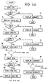
- the system manager 1 When a user inserts his card into the card unit 13, the system manager 1 is powered on and the processing operation of these figures starts. After start, the program CRD for the card unit 13, which is stored in the area 61 of the memory 5, is started (step 71) and then it is checked whether or not the inserted card is registered and valid (step 72).
- the communication unit 33 When the CMNCTN is started at step 77, the communication unit 33 at first executes the self-diagnosis (step 78). If it is judged at step 78 that the communication unit 33 is not normal, a guidance is displayed in the display device 15 (step 79), and the processing operation ends. This guidance is, for example, "Communication unit is abnormal. Call a service station.”
- step 83 if it is judged at this step that the disk unit 29 is normal, a record of the card inserted in the card unit 13 is read (step 88), and the read-out record is displayed in the system display device 15 (step 89).
- a guidance is displayed in the system display device 15 (step 93).
- An example of this guidance is "Change is not allowed. Bring an automobile into a parking condition or use an internal memory ? Input "1”, if an automobile is brought into a parking condition, "2”, if you use an internal memory, and "3”, if you do not use an internal memory.”
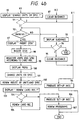
- a user carries out the change of units to be used and their specifications by manipulating the ten-key 11 in accordance with the displayed menu (step 101).
- a first item i.e., "1 ENGINE CONTROL UNIT”
- the user inputs "1" by the ten-key 11, this means that the characteristic of the economic drive is selected as a specification for the engine control unit 19.
- That numerical input data is temporarily stored in an appropriate portion of the memory 5 and the highlight in the menu is shifted to a second item, i.e., "2 POWER STEERING UNIT".
- step 106 If a user inputs "2" at step 104, the processing operation goes to step 106 without renewing the card record. If he selects "1" at step 104, the processing operation goes to step 106 after the card record is renewed (step 105).
- the renewal of the card record at this step has the following advantage. When the user is going to use another automobile next time, he can use the another automobile with the same drive characteristic or accessories as selected or prepared this time, if he only inserts the card in the card unit 13 of the another automobile.
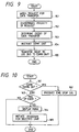
- step 115 is a step which is executed only when a guidance of "Invalid card” is displayed, as described later. The processing operation as mentioned above is repeated, until the card is inserted correctly.
- step 114 the same processing operation as described above is carried out, and if the card is taken out from the card unit 13, the processing operation returns to step 112, after the guidance displayed at step 117 is cleared (step 115). Thereafter, the same processing operation as mentioned above is conducted, and this loop operation continues until the inserted card, which is not registered, is taken out and a registered card is inserted.
- step 151 After start of this task, it is watched at step 151 whether or not any of the units generates a request for data transfer. If such a request is caught, the priority of the request is discriminated at step 152, and then the order of data transfer is determined in accordance with the priority (step 153). The result of the determination in step 153 is transferred to the communication unit 33 (step 154).
- step 161 After start of this task, it is discriminated whether or not a card is taken out from the card unit 13 (step 161). If the card is taken out, this means that a user has an intention to stop the operation of an engine, and therefore an engine stop signal is produced (step 162).
- step 163 it is discriminated at step 163 whether or not any request of a user occurs. Such a request is produced by a user's manipulation of the change/register button switch 57 (Fig. 2). If there is no request, the processing operation ends. If, however, a user's request is detected to occur, a picture of the menu as shown in Fig. 8 is displayed in the system display device 15 (step 164).
- a program for the air conditioner unit 25 is initiated (step 165). Thereafter, the air conditioner unit 25 starts to execute the program, whereby necessary guidances are displayed in the system display device 15 and the user can dialogically achieve the change of the specifications of an air conditioner, such as set values of a room temperature and/or an air quantity of a blower, for example, in accordance with the displayed guidances.
- an air conditioner such as set values of a room temperature and/or an air quantity of a blower, for example, in accordance with the displayed guidances.
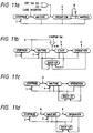
- Those units, which are in the status of stoppage, are brought into the status of waiting by inserting a card. If a user inputs his identification ID (cf. step 74 of Fig. 4a) or turns on the key switch 51 (Fig. 2) by using a key (cf. steps 73 and 76 of the same), those units are brought into the status of operation and, after execution of the necessary steps, the set-up instruction signal A is produced (cf. steps 96 and 106 of Fig. 4b).
- the system manager 1 executes the interruption processing operation as shown in Fig. 6, whereby those units are maintained in the status of waiting, until the signal B disappears. Further, when the stop signal C is generated (cf. step 162 of Fig. 10), those units shifts their status to the stoppage from any status thereof.
- Fig. 11b there is shown the status transfer of the operation of the engine control unit 19.
- This unit 19 which is in the status of stoppage, shifts its status to the waiting by receiving the set-up instruction signal A produced as above.
- the engine control unit 19 will be subject to the self-diagnosis in this status. If any abnormality is found thereby, this unit 19 is shifted to the status of back-up. Contents of the back-up depends on an engine control unit installed, however they have no direct relation with the present invention.
- the status transfer in the operation of the transmission control unit 21 and the power steering unit 23 is almost the same as that of the engine control unit 19, as mentioned above.
- the unit 31 falls into the status of waiting, even if it is in any status. Further, the stop signal C shifts the status of the unit 31 to the stoppage, even if it is in any status.
- various devices installed in an automobile such as power train devices and accessories, can be activated or brought into the operable condition by a card, whereby the easy and flexible management of automobiles can be realized especially in the case where plural users use one or more automobiles in common.
- the present invention has a further advantage in such a control apparatus for an automobile that is provided with a system manager, which manages and controls the operation of control units for the various devices and accessories, and can select some necessary ones from among the control units and their specifications.
- a system manager which manages and controls the operation of control units for the various devices and accessories, and can select some necessary ones from among the control units and their specifications.
Description
Claims (9)
- A control apparatus for an automobile comprising a microprocessor control system for executing predetermined processing to control the operation of various devices and accessories (19, 21, 23, 25, 27, 29, 31, 33, 35, 37) installed in the automobile, said microprocessor comprises a system manager (1), including a central processing unit (3) and a memory (5) coupled with each other for initiating and managing the operation of units for controlling and operating the various devices and accessories (19, 21, 23, 25, 27, 29, 31, 33, 35, 37) and means for identifying a user of the automobile on the basis of an inputted information,said identifying means includes an information read unit (13), coupled to said system manager (1), in which a portable recording medium with information recorded thereon is inserted, whereby, in response to the insertion of said recording medium, said system manager (1) executes a checking program stored in the memory (5) on the basis of the information recorded on the recording medium to check the validity and the correct use of the recording medium inserted and initiates the execution of a program stored in the memory (5) for the controlling and operating units, only when the inserted recording medium is judged to be valid and correct by the execution of said checking program,
characterized in thatthe information read unit (13) is adapted to record on the portable recording medium specifications of control units selected by a user. - A control apparatus according to claim 1,
wherein the information recorded on said recording medium includes a code particularly assigned to the recording medium and a list of codes of recording media registered in advance is provided, wherein when said recording medium is inserted in the information read/write unit (13), it is judged by referring to the code list whether or not the recording medium inserted is a registered one, and wherein said system manager (1) is initiated, only if the recording medium is judged to be registered. - A control apparatus according to claim 1,
wherein said system manager (1) is provided with means (11) capable of inputting at least code data and the information recorded in said recording medium includes an identification code, which is assigned to an individual user using the recording medium, and wherein said system manager (1) is initiated, if an identification code inputted by a user is coincident with the identification code recorded in said recording medium inserted in the information read/write unit. - A control apparatus according to claim 3,
wherein when a user inserts said recording medium in the information read/write unit (13) and can not input a correct idendification code within a predetermined number of times of trying to input the identification code, a code or flag indicating an invalid card is recorded in said recording medium, whereby said system manager (1) can no longer be initiated with said recording medium. - A control apparatus according to claim 1,
wherein the user selects control units from among the control units installed in the automobile in advance by the user's own manipulation in accordance with guidances displayed on a display device (15) by the system manager (1), and wherein the thus selected control units are registered in the memory (5) of the system manager (1) in order to make those control units operable and recorded by the information read/write unit (13) on said recording medium. - A control apparatus according to claim 5,
wherein the registration and change of control units to be used and their specifications are allowed only during a certain condition of the automobile. - A control apparatus according to claim 6,
wherein the registration and change of control units and their specifications, which directly relates to the travel of the automobile, such as an engine control unit (19), a transmission control unit (21) and a power steering unit (23) is not allowed during the time the automobile travels. - A control apparatus according to claim 7,
wherein when the automobile travels, part of the guidances displayed on the display device (13), which concerns the change of the units and their specifications directly relating to the travel of the automobile, is masked. - A control apparatus according to claim 5,
wherein the control units installed in the automobile includes a disk unit (29), in which a floppy disk can be inserted, and, when the disk unit (29) is registered in the system manager (1), the alteration of programs for the devices and accessories can be carried out by the floppy disk.
Applications Claiming Priority (2)
| Application Number | Priority Date | Filing Date | Title |
|---|---|---|---|
| JP92863/89 | 1989-04-14 | ||
| JP9286389 | 1989-04-14 |
Publications (4)
| Publication Number | Publication Date |
|---|---|
| EP0392411A2 EP0392411A2 (en) | 1990-10-17 |
| EP0392411A3 EP0392411A3 (en) | 1992-01-08 |
| EP0392411B1 EP0392411B1 (en) | 1994-03-02 |
| EP0392411B2 true EP0392411B2 (en) | 1999-01-07 |
Family
ID=14066267
Family Applications (1)
| Application Number | Title | Priority Date | Filing Date |
|---|---|---|---|
| EP90106737A Expired - Lifetime EP0392411B2 (en) | 1989-04-14 | 1990-04-09 | A control apparatus for automobiles |
Country Status (4)
| Country | Link |
|---|---|
| US (1) | US5091856A (en) |
| EP (1) | EP0392411B2 (en) |
| KR (1) | KR100191128B1 (en) |
| DE (1) | DE69006885T3 (en) |
Cited By (1)
| Publication number | Priority date | Publication date | Assignee | Title |
|---|---|---|---|---|
| CN111025999A (en) * | 2019-12-27 | 2020-04-17 | 上海昶枫科技有限公司 | Energy-saving control process for automobile electronic controller |
Families Citing this family (155)
| Publication number | Priority date | Publication date | Assignee | Title |
|---|---|---|---|---|
| DE3927993C1 (en) * | 1989-08-24 | 1990-09-27 | Blaupunkt-Werke Gmbh, 3200 Hildesheim, De | |
| DE69027507T2 (en) * | 1989-10-27 | 1997-01-30 | Hitachi Ltd | Motor vehicle control system and control unit therefor |
| JP2834808B2 (en) * | 1989-12-08 | 1998-12-14 | 三菱電機株式会社 | Automotive control device |
| US5680313A (en) * | 1990-02-05 | 1997-10-21 | Caterpillar Inc. | System and method for detecting obstacles in a road |
| JP3165430B2 (en) * | 1990-08-10 | 2001-05-14 | マツダ株式会社 | Multiplex transmission equipment for vehicles |
| GB9101227D0 (en) * | 1991-01-19 | 1991-02-27 | Lucas Ind Plc | Method of and apparatus for arbitrating between a plurality of controllers,and control system |
| DE69205238T2 (en) * | 1991-08-01 | 1996-05-02 | Philips Electronics Nv | Security system for one device. |
| US5257190A (en) * | 1991-08-12 | 1993-10-26 | Crane Harold E | Interactive dynamic realtime management system for powered vehicles |
| IT1250890B (en) * | 1991-12-23 | 1995-04-21 | Fiat Auto Spa | VEHICLE WITH REMOTE CONTROL DEVICE FOR ELECTRICAL OR ELECTRONIC SYSTEMS AND ON-BOARD EQUIPMENT. |
| JPH0619848A (en) * | 1992-06-29 | 1994-01-28 | Honda Motor Co Ltd | On-vehicle individual information storage/reproduction device |
| US6205374B1 (en) * | 1993-07-01 | 2001-03-20 | Mazda Motor Corporation | Vehicle characteristic change system and method |
| JP3321837B2 (en) * | 1992-08-06 | 2002-09-09 | 株式会社日立製作所 | Vehicle diagnostic control method |
| US5941925A (en) * | 1992-11-26 | 1999-08-24 | Robert Bosch Gmbh | Method and arrangement for controlling a motor vehicle |
| DE4239711B4 (en) * | 1992-11-26 | 2005-03-31 | Robert Bosch Gmbh | Method and device for controlling a vehicle |
| US5513107A (en) * | 1992-12-17 | 1996-04-30 | Ford Motor Company | Methods and apparatus for controlling operating subsystems of a motor vehicle |
| US5487002A (en) * | 1992-12-31 | 1996-01-23 | Amerigon, Inc. | Energy management system for vehicles having limited energy storage |
| DE4301436C2 (en) * | 1993-01-20 | 1996-06-13 | Kaiser Hans Christian | Security system |
| DE4301540A1 (en) * | 1993-01-21 | 1994-07-28 | Vdo Schindling | Device for registering the users of a motor vehicle |
| DE4303620A1 (en) * | 1993-02-02 | 1994-08-04 | Esd Elect Syst Design | Read / write unit for electronic devices |
| SE500103C2 (en) * | 1993-03-23 | 1994-04-18 | Raivo Kask | Anti-theft device |
| US5554891A (en) * | 1993-03-30 | 1996-09-10 | Asahi Denso Kabushiki Kaisha | Antitheft device for a vehicle |
| IT1260963B (en) * | 1993-08-06 | 1996-04-29 | Weber Srl | SAFETY DEVICE FOR AN ANTI-THEFT SYSTEM FOR MEANS OF LOCOMATION |
| IT1260965B (en) * | 1993-08-06 | 1996-04-29 | Weber Srl | CONTROL DEVICE FOR AN ANTI-THEFT SYSTEM FOR MEANS OF LOCOMATION |
| JP3529383B2 (en) * | 1993-08-26 | 2004-05-24 | シーメンス アクチエンゲゼルシヤフト | Automotive control unit |
| DE4414644A1 (en) * | 1993-10-29 | 1995-05-04 | Bosch Gmbh Robert | Vehicle security arrangement |
| US5583383A (en) * | 1993-10-29 | 1996-12-10 | Robert Bosch Gmbh | Vehicle security system |
| US5525977A (en) * | 1993-12-06 | 1996-06-11 | Prince Corporation | Prompting system for vehicle personalization |
| US5664113A (en) * | 1993-12-10 | 1997-09-02 | Motorola, Inc. | Working asset management system and method |
| DE4414216C1 (en) * | 1994-04-23 | 1995-04-06 | Daimler Benz Ag | Device for protecting a motor vehicle against use by third parties, with personalisation of the driving authorisation |
| US5555502A (en) * | 1994-05-11 | 1996-09-10 | Geo Ventures | Display and control apparatus for the electronic systems of a motor vehicle |
| US5561332A (en) * | 1994-06-10 | 1996-10-01 | Nissan Motor Co., Ltd. | Vehicle anti-theft device having back-up means should the ECU fail, but preventing theft if the ECU was intentionally damaged |
| JPH0872633A (en) * | 1994-09-01 | 1996-03-19 | Sumitomo Wiring Syst Ltd | Current distributing device of automobile |
| FR2724742A1 (en) * | 1994-09-21 | 1996-03-22 | Peugeot | Networked sub=system guidance management system for motor vehicle |
| FR2727072B1 (en) * | 1994-11-22 | 1997-01-03 | Thouvenot Raymond | AUTOMOBILE THEFT REALIZED WITH THE STARTER |
| DE4445110A1 (en) * | 1994-12-19 | 1996-06-20 | Bosch Gmbh Robert | Circuit arrangement for function modules that can be arranged in a motor vehicle |
| EP1398293A3 (en) | 1995-03-10 | 2005-02-09 | Michael C. Ryan | Fluid delivery control nozzle |
| US5696410A (en) * | 1995-07-05 | 1997-12-09 | Ford Motor Company | Override circuit for enabling internal combustion engine |
| DE19537419A1 (en) * | 1995-10-07 | 1997-04-10 | Philips Patentverwaltung | Car radio with an electronic anti-theft device |
| DE19624762A1 (en) * | 1996-06-21 | 1998-01-02 | Bosch Gmbh Robert | Procedure for monitoring access authorization in a radio receiver and radio receiver |
| US6434459B2 (en) * | 1996-12-16 | 2002-08-13 | Microsoft Corporation | Automobile information system |
| DE19710082A1 (en) * | 1997-03-12 | 1998-10-01 | Deere & Co | Drive system for commercial vehicles |
| FR2761017B1 (en) * | 1997-03-21 | 2002-03-01 | Volkswagen Ag | DEVICE FOR AUTOMATIC SELECTION BETWEEN COMFORT AND COST-EFFICIENT OPERATION OF A MOTOR VEHICLE |
| US6119060A (en) * | 1997-03-31 | 2000-09-12 | Mazda Motor Corporation | Electronic equipment apparatus and electronic equipment assembly |
| DE19715880C1 (en) * | 1997-04-16 | 1998-07-23 | Mc Micro Compact Car Ag | System of wire bus networked controllers with reduced residual current consumption |
| DE19720285A1 (en) * | 1997-05-15 | 1998-11-19 | Bosch Gmbh Robert | Process for the tamper-proof configuration of a motor vehicle control unit and control unit |
| JP3338634B2 (en) * | 1997-07-09 | 2002-10-28 | 株式会社デンソー | Distributed processing type control unit |
| US5938716A (en) * | 1997-09-08 | 1999-08-17 | Cummins Engine Company, Inc. | System for customizing vehicle engine control computer operation |
| WO1999017976A1 (en) * | 1997-10-02 | 1999-04-15 | Mitsubishi Denki Kabushiki Kaisha | Controller for automobile |
| US6070687A (en) * | 1998-02-04 | 2000-06-06 | Trw Inc. | Vehicle occupant restraint device, system, and method having an anti-theft feature |
| US6144905A (en) * | 1998-03-18 | 2000-11-07 | Motorola, Inc. | Method for registering vehicular bus functionality |
| US6430488B1 (en) * | 1998-04-10 | 2002-08-06 | International Business Machines Corporation | Vehicle customization, restriction, and data logging |
| US7158871B1 (en) | 1998-05-07 | 2007-01-02 | Art - Advanced Recognition Technologies Ltd. | Handwritten and voice control of vehicle components |
| KR100754497B1 (en) * | 1998-05-07 | 2007-09-03 | 뉘앙스 커뮤니케이션스 이스라엘, 리미티드 | Handwritten and voice control of vehicle components |
| DE19832531A1 (en) * | 1998-07-22 | 2000-02-10 | Bosch Gmbh Robert | Control for a plurality of electrical consumers of a motor vehicle |
| US6314351B1 (en) * | 1998-08-10 | 2001-11-06 | Lear Automotive Dearborn, Inc. | Auto PC firewall |
| SE9804469L (en) * | 1998-12-21 | 2000-06-22 | Volvo Ab | Device for a motor vehicle |
| DE19907795A1 (en) * | 1999-02-24 | 2000-09-14 | Daimler Chrysler Ag | Method for supporting a user of a motor vehicle in the operation of components of the motor vehicle and an associated device |
| US6570486B1 (en) | 1999-04-09 | 2003-05-27 | Delphi Automotive Systems | Passive remote access control system |
| US6882917B2 (en) * | 1999-07-30 | 2005-04-19 | Oshkosh Truck Corporation | Steering control system and method |
| US7107129B2 (en) | 2002-02-28 | 2006-09-12 | Oshkosh Truck Corporation | Turret positioning system and method for a fire fighting vehicle |
| US6553290B1 (en) * | 2000-02-09 | 2003-04-22 | Oshkosh Truck Corporation | Equipment service vehicle having on-board diagnostic system |
| US20030158635A1 (en) * | 1999-07-30 | 2003-08-21 | Oshkosh Truck Corporation | Firefighting vehicle with network-assisted scene management |
| US7024296B2 (en) * | 1999-07-30 | 2006-04-04 | Oshkosh Truck Corporation | Control system and method for an equipment service vehicle |
| US6922615B2 (en) * | 1999-07-30 | 2005-07-26 | Oshkosh Truck Corporation | Turret envelope control system and method for a fire fighting vehicle |
| US7184862B2 (en) | 1999-07-30 | 2007-02-27 | Oshkosh Truck Corporation | Turret targeting system and method for a fire fighting vehicle |
| US20040133319A1 (en) * | 1999-07-30 | 2004-07-08 | Oshkosh Truck Corporation | User interface and method for vehicle control system |
| US7072745B2 (en) | 1999-07-30 | 2006-07-04 | Oshkosh Truck Corporation | Refuse vehicle control system and method |
| US6421593B1 (en) | 1999-07-30 | 2002-07-16 | Pierce Manufacturing Inc. | Military vehicle having cooperative control network with distributed I/O interfacing |
| US7006902B2 (en) * | 1999-07-30 | 2006-02-28 | Oshkosh Truck Corporation | Control system and method for an equipment service vehicle |
| US6993421B2 (en) * | 1999-07-30 | 2006-01-31 | Oshkosh Truck Corporation | Equipment service vehicle with network-assisted vehicle service and repair |
| US6909944B2 (en) * | 1999-07-30 | 2005-06-21 | Oshkosh Truck Corporation | Vehicle control system and method |
| US7729831B2 (en) * | 1999-07-30 | 2010-06-01 | Oshkosh Corporation | Concrete placement vehicle control system and method |
| US6885920B2 (en) * | 1999-07-30 | 2005-04-26 | Oshkosh Truck Corporation | Control system and method for electric vehicle |
| US7162332B2 (en) | 1999-07-30 | 2007-01-09 | Oshkosh Truck Corporation | Turret deployment system and method for a fire fighting vehicle |
| US7127331B2 (en) | 1999-07-30 | 2006-10-24 | Oshkosh Truck Corporation | Turret operator interface system and method for a fire fighting vehicle |
| US7184866B2 (en) | 1999-07-30 | 2007-02-27 | Oshkosh Truck Corporation | Equipment service vehicle with remote monitoring |
| DE19955890B4 (en) * | 1999-11-20 | 2006-10-05 | Robert Bosch Gmbh | Method and device for issuing operating instructions |
| DE19958564B4 (en) * | 1999-12-04 | 2008-11-13 | Adam Opel Ag | Device for securing motor vehicles against manipulation |
| DE10000922A1 (en) * | 2000-01-12 | 2001-07-19 | Volkswagen Ag | Electronic system |
| US6681987B1 (en) | 2000-03-09 | 2004-01-27 | Meritor Heavy Vehicle Systems, Llc | Smart card system for heavy vehicles |
| US6957172B2 (en) * | 2000-03-09 | 2005-10-18 | Smartsignal Corporation | Complex signal decomposition and modeling |
| US6363304B1 (en) | 2000-06-12 | 2002-03-26 | Meritor Heavy Vehicle Technology, Llc | Personal data computer for vehicle monitoring |
| US6772061B1 (en) | 2000-08-18 | 2004-08-03 | Bombardier Recreational Products Inc. | System, method, and apparatus for controlling vehicle performance |
| US6663010B2 (en) | 2001-01-22 | 2003-12-16 | Meritor Heavy Vehicle Technology, Llc | Individualized vehicle settings |
| US6356824B1 (en) | 2001-01-23 | 2002-03-12 | Meritor Heavy Vehicle Technology, Llc | Vehicle systems data storage |
| US6516251B1 (en) | 2001-01-23 | 2003-02-04 | Meritor Heavy Vehicle Technology, Llc. | Automated vehicle shutdown sequence |
| US7379797B2 (en) * | 2001-01-31 | 2008-05-27 | Oshkosh Truck Corporation | System and method for braking in an electric vehicle |
| US7277782B2 (en) * | 2001-01-31 | 2007-10-02 | Oshkosh Truck Corporation | Control system and method for electric vehicle |
| US7376839B2 (en) | 2001-05-04 | 2008-05-20 | Cubic Corporation | Smart card access control system |
| JP2002347479A (en) * | 2001-05-29 | 2002-12-04 | Denso Corp | Vehicle integrated control system |
| US6587768B2 (en) | 2001-08-08 | 2003-07-01 | Meritor Heavy Vehicle Technology, Llc | Vehicle inspection and maintenance system |
| JP2004522237A (en) * | 2001-08-10 | 2004-07-22 | テルシン・カンパニー・リミテッド | Vehicle data collection and vehicle diagnosis system and method using smart card, and automatic setting method of vehicle convenience device |
| US7254468B2 (en) * | 2001-12-21 | 2007-08-07 | Oshkosh Truck Corporation | Multi-network control system for a vehicle |
| US7302320B2 (en) * | 2001-12-21 | 2007-11-27 | Oshkosh Truck Corporation | Failure mode operation for an electric vehicle |
| US20050113996A1 (en) * | 2001-12-21 | 2005-05-26 | Oshkosh Truck Corporation | Ambulance control system and method |
| US7792618B2 (en) | 2001-12-21 | 2010-09-07 | Oshkosh Corporation | Control system and method for a concrete vehicle |
| US6535802B1 (en) | 2002-01-25 | 2003-03-18 | Meritor Heavy Vehicle Technology, Llc | Quick check vehicle diagnostics |
| US20030222982A1 (en) * | 2002-03-28 | 2003-12-04 | Hamdan Majil M. | Integrated video/data information system and method for application to commercial vehicles to enhance driver awareness |
| JP2004042741A (en) * | 2002-07-10 | 2004-02-12 | Bosch Automotive Systems Corp | Electronic controller for vehicle with theft prevention function |
| US7412307B2 (en) * | 2002-08-02 | 2008-08-12 | Oshkosh Truck Corporation | Refuse vehicle control system and method |
| US7401352B2 (en) * | 2002-08-30 | 2008-07-15 | International Business Machines Corporation | Secure system and method for enforcement of privacy policy and protection of confidentiality |
| US20040083040A1 (en) * | 2002-10-28 | 2004-04-29 | Thomas Parrott | Vehicle data retrieval system |
| DE10253765A1 (en) * | 2002-11-19 | 2004-06-09 | Daimlerchrysler Ag | Control device determining regulation or control characteristic of automobile system using stored computer program for provision of output signal for automobile system from received input signal |
| US20070035625A9 (en) * | 2002-12-20 | 2007-02-15 | Hamdan Majed M | Vehicle video processing system |
| ATE492085T1 (en) | 2003-01-28 | 2011-01-15 | Cellport Systems Inc | A SYSTEM AND METHOD FOR CONTROLLING APPLICATIONS' ACCESS TO PROTECTED RESOURCES WITHIN A SECURE VEHICLE TELEMATICS SYSTEM |
| DE10334587B4 (en) * | 2003-07-28 | 2018-12-06 | Volkswagen Ag | Method and device for driver-dependent adjustment of vehicle functions |
| US20050029409A1 (en) * | 2003-08-04 | 2005-02-10 | Nestor Tagle | Din stereo slot mountable automobile gauge cluster |
| JP2005088801A (en) * | 2003-09-18 | 2005-04-07 | Denso Corp | Information processing system |
| DE10348754A1 (en) * | 2003-10-21 | 2005-06-30 | Zf Friedrichshafen Ag | Method for transmitting characteristics or characteristics of an automatic transmission in an electronic control |
| US20050093975A1 (en) * | 2003-10-30 | 2005-05-05 | Hamdan Majed M. | Adaptation of vision systems for commerical vehicles |
| JP2005165587A (en) * | 2003-12-02 | 2005-06-23 | Yazaki Corp | Onboard meter system |
| US7680574B2 (en) * | 2004-03-04 | 2010-03-16 | Gm Global Technology Operations, Inc. | Vehicle information system with steering wheel controller |
| JP4437468B2 (en) * | 2004-12-06 | 2010-03-24 | 富士通テン株式会社 | Electronic control device for vehicle |
| JP4802859B2 (en) * | 2005-07-04 | 2011-10-26 | 株式会社デンソー | Manual operation device |
| US7640085B2 (en) * | 2005-11-10 | 2009-12-29 | Gm Global Technology Operations, Inc. | Method and apparatus to provide vehicle information to a requestor |
| JP2009536594A (en) * | 2006-05-09 | 2009-10-15 | ロッキード・マーチン・コーポレイション | Mobile traction control system and method |
| CN101500828A (en) * | 2006-05-09 | 2009-08-05 | 洛克希德马丁公司 | Mobility traction control system and method |
| US7873610B2 (en) | 2006-05-26 | 2011-01-18 | Andrew S Poulsen | Meta-configuration of profiles |
| US8947531B2 (en) | 2006-06-19 | 2015-02-03 | Oshkosh Corporation | Vehicle diagnostics based on information communicated between vehicles |
| US8139109B2 (en) | 2006-06-19 | 2012-03-20 | Oshkosh Corporation | Vision system for an autonomous vehicle |
| US8368508B2 (en) * | 2006-07-26 | 2013-02-05 | Jack Chen | Method of keying an identification code into a controlling member and into a function controller |
| US8275577B2 (en) | 2006-09-19 | 2012-09-25 | Smartsignal Corporation | Kernel-based method for detecting boiler tube leaks |
| US7732938B2 (en) * | 2006-10-12 | 2010-06-08 | Beat-Sonic Co., Ltd. | Adapter for use with vehicle-mounted electronics |
| US8392882B2 (en) | 2006-11-30 | 2013-03-05 | Caterpillar Inc. | Engine state-based control of software functions |
| US8311774B2 (en) * | 2006-12-15 | 2012-11-13 | Smartsignal Corporation | Robust distance measures for on-line monitoring |
| US8027293B2 (en) | 2007-07-16 | 2011-09-27 | Cellport Systems, Inc. | Communication channel selection and use |
| US8457867B2 (en) | 2007-07-26 | 2013-06-04 | Bombardier Recreational Products Inc. | Method for operating a vehicle |
| CA2737243A1 (en) * | 2007-09-20 | 2009-03-26 | Better Place GmbH | Electric vehicle network |
| US8589049B2 (en) * | 2007-12-03 | 2013-11-19 | Lockheed Martin Corporation | GPS-based system and method for controlling vehicle characteristics based on terrain |
| US8145402B2 (en) * | 2007-12-05 | 2012-03-27 | Lockheed Martin Corporation | GPS-based traction control system and method using data transmitted between vehicles |
| US20090319131A1 (en) * | 2008-06-24 | 2009-12-24 | International Business Machines Corporation | Vehicle macro recording and playback system able to operate across subsystem boundaries |
| US20110223459A1 (en) * | 2008-09-19 | 2011-09-15 | Yoav Heichal | Multi-Motor Latch Assembly |
| US8006793B2 (en) * | 2008-09-19 | 2011-08-30 | Better Place GmbH | Electric vehicle battery system |
| US7993155B2 (en) | 2008-09-19 | 2011-08-09 | Better Place GmbH | System for electrically connecting batteries to electric vehicles |
| US20100094496A1 (en) * | 2008-09-19 | 2010-04-15 | Barak Hershkovitz | System and Method for Operating an Electric Vehicle |
| US8229639B2 (en) * | 2009-02-17 | 2012-07-24 | Lockheed Martin Corporation | System and method for stability control |
| US8244442B2 (en) * | 2009-02-17 | 2012-08-14 | Lockheed Martin Corporation | System and method for stability control of vehicle and trailer |
| US8352120B2 (en) * | 2009-02-17 | 2013-01-08 | Lockheed Martin Corporation | System and method for stability control using GPS data |
| JP5551388B2 (en) * | 2009-07-21 | 2014-07-16 | トヨタ自動車株式会社 | Power saving system |
| US8118147B2 (en) | 2009-09-11 | 2012-02-21 | Better Place GmbH | Cable dispensing system |
| US7972167B2 (en) * | 2009-09-14 | 2011-07-05 | Better Place GmbH | Electrical connector with a flexible blade-shaped housing with a handle with an opening |
| US8035341B2 (en) * | 2010-07-12 | 2011-10-11 | Better Place GmbH | Staged deployment for electrical charge spots |
| US8660980B2 (en) | 2011-07-19 | 2014-02-25 | Smartsignal Corporation | Monitoring system using kernel regression modeling with pattern sequences |
| US8620853B2 (en) | 2011-07-19 | 2013-12-31 | Smartsignal Corporation | Monitoring method using kernel regression modeling with pattern sequences |
| US9250625B2 (en) | 2011-07-19 | 2016-02-02 | Ge Intelligent Platforms, Inc. | System of sequential kernel regression modeling for forecasting and prognostics |
| US9256224B2 (en) | 2011-07-19 | 2016-02-09 | GE Intelligent Platforms, Inc | Method of sequential kernel regression modeling for forecasting and prognostics |
| US9061645B2 (en) | 2013-02-15 | 2015-06-23 | Clever Devices, Ltd | Methods and apparatus for transmission control of a transit vehicle |
| US9845191B2 (en) | 2013-08-02 | 2017-12-19 | Oshkosh Corporation | Ejector track for refuse vehicle |
| US9602624B2 (en) | 2013-09-30 | 2017-03-21 | AT&T Intellectual Property I, L.L.P. | Facilitating content management based on profiles of members in an environment |
| US10375901B2 (en) | 2014-12-09 | 2019-08-13 | Mtd Products Inc | Blower/vacuum |
| US10173642B2 (en) | 2015-01-23 | 2019-01-08 | Continental Automotive Systems, Inc. | Telematics system with PIN-controlled external SIM to prevent vehicle piracy |
| US9540015B2 (en) | 2015-05-04 | 2017-01-10 | At&T Intellectual Property I, L.P. | Methods and apparatus to alter a vehicle operation |
| CN105068527A (en) * | 2015-07-09 | 2015-11-18 | 北汽福田汽车股份有限公司 | Electric equipment monitoring method and system of automobile |
| FR3065823B1 (en) * | 2017-04-27 | 2020-08-14 | Peugeot Citroen Automobiles Sa | DEVICE FOR MONITORING THE FUNCTIONS OF A VEHICLE BASED ON THE PERSONAL CONFIGURATION (S) OF THE USER (S) |
| US10974729B2 (en) | 2018-08-21 | 2021-04-13 | At&T Intellectual Property I, L.P. | Application and portability of vehicle functionality profiles |
Family Cites Families (10)
| Publication number | Priority date | Publication date | Assignee | Title |
|---|---|---|---|---|
| US4204255A (en) * | 1976-09-09 | 1980-05-20 | Keiper Automobiltechnik Gmbh & Co Kg | Apparatus for adjusting a vehicle seat |
| JPS577737A (en) * | 1980-06-13 | 1982-01-14 | Aisin Seiki Co Ltd | Controller of door and seat on vehicle |
| DE3313098C1 (en) * | 1983-04-12 | 1984-10-11 | Daimler-Benz Ag, 7000 Stuttgart | Electronic lock system |
| JPS6121843A (en) * | 1984-07-10 | 1986-01-30 | Nippon Soken Inc | Automatic resetting apparatus for appliance for crew |
| DE3514438C1 (en) * | 1985-04-20 | 1986-09-18 | Porsche Ag | Central operating input and information output for additional devices of vehicles |
| US4706194A (en) * | 1985-12-13 | 1987-11-10 | United Technologies Automotive, Inc. | Multiplex control system for memory seat or the like load |
| JPS6326138A (en) * | 1986-07-18 | 1988-02-03 | Mitsubishi Electric Corp | On-vehicle centralized control display system |
| JP2556501B2 (en) * | 1987-02-09 | 1996-11-20 | 株式会社日立製作所 | Driver's license card system |
| US4838377A (en) * | 1987-03-02 | 1989-06-13 | Clarion, Co., Ltd. | Car electronic device having antitheft mechanism |
| JP2753225B2 (en) * | 1987-03-13 | 1998-05-18 | 株式会社日立製作所 | In-vehicle control device |
-
1990
- 1990-04-09 DE DE69006885T patent/DE69006885T3/en not_active Expired - Fee Related
- 1990-04-09 EP EP90106737A patent/EP0392411B2/en not_active Expired - Lifetime
- 1990-04-11 US US07/507,466 patent/US5091856A/en not_active Expired - Lifetime
- 1990-04-13 KR KR1019900005144A patent/KR100191128B1/en not_active IP Right Cessation
Cited By (1)
| Publication number | Priority date | Publication date | Assignee | Title |
|---|---|---|---|---|
| CN111025999A (en) * | 2019-12-27 | 2020-04-17 | 上海昶枫科技有限公司 | Energy-saving control process for automobile electronic controller |
Also Published As
| Publication number | Publication date |
|---|---|
| EP0392411B1 (en) | 1994-03-02 |
| KR100191128B1 (en) | 1999-06-15 |
| DE69006885T2 (en) | 1994-06-16 |
| DE69006885T3 (en) | 1999-05-20 |
| KR900016841A (en) | 1990-11-14 |
| EP0392411A2 (en) | 1990-10-17 |
| DE69006885D1 (en) | 1994-04-07 |
| EP0392411A3 (en) | 1992-01-08 |
| US5091856A (en) | 1992-02-25 |
Similar Documents
| Publication | Publication Date | Title |
|---|---|---|
| EP0392411B2 (en) | A control apparatus for automobiles | |
| US5467277A (en) | Apparatus and method for automobile control using a control characteristic which can be adjusted by the driver | |
| EP0189204B1 (en) | Operation data recording system | |
| EP1569174B1 (en) | Data recording apparatus and data recording method | |
| US7505839B2 (en) | Vehicular data recording device | |
| US5758300A (en) | Diagnosis system for motor vehicles and the method thereof | |
| JP3333378B2 (en) | Vehicle diagnostic method and device | |
| EP1569176B1 (en) | Operator-side system and mode file identifying method | |
| JP3552491B2 (en) | Vehicle data backup system and in-vehicle terminal device constituting the system | |
| US20110119614A1 (en) | Method for providing information to a user of a motor vehicle | |
| JP2004522237A (en) | Vehicle data collection and vehicle diagnosis system and method using smart card, and automatic setting method of vehicle convenience device | |
| JP2008267266A (en) | Economic run system, control program and economic run state notifying device | |
| JPH1024784A (en) | Vehicle, vehicle card system and vehicle maintenance method | |
| US5557553A (en) | Computer assisted time study system | |
| JP4345119B2 (en) | In-vehicle electronic control unit and how to replace the same electronic control unit | |
| JPH09210865A (en) | Method and apparatus for diagnosing vehicle | |
| JPH08238951A (en) | Control device for automobile | |
| JP2834268B2 (en) | In-vehicle control device | |
| JP2001130351A (en) | Controller for automobile | |
| JP5618682B2 (en) | Vehicle operation recording device, operation record control method, and operation record program | |
| JP3528145B2 (en) | Vehicle operation information collection method and device | |
| JPH09210868A (en) | Method and apparatus for diagnosing vehicle | |
| KR19990003454A (en) | Automatic driving recorder and method of automobile | |
| JP4304893B2 (en) | Electronic odometer for automobile | |
| JPH09210870A (en) | Method and apparatus for diagnosing vehicle |
Legal Events
| Date | Code | Title | Description |
|---|---|---|---|
| PUAI | Public reference made under article 153(3) epc to a published international application that has entered the european phase |
Free format text: ORIGINAL CODE: 0009012 |
|
| AK | Designated contracting states |
Kind code of ref document: A2 Designated state(s): DE FR GB |
|
| 17P | Request for examination filed |
Effective date: 19901108 |
|
| PUAL | Search report despatched |
Free format text: ORIGINAL CODE: 0009013 |
|
| AK | Designated contracting states |
Kind code of ref document: A3 Designated state(s): DE FR GB |
|
| 17Q | First examination report despatched |
Effective date: 19920921 |
|
| GRAA | (expected) grant |
Free format text: ORIGINAL CODE: 0009210 |
|
| AK | Designated contracting states |
Kind code of ref document: B1 Designated state(s): DE FR GB |
|
| REF | Corresponds to: |
Ref document number: 69006885 Country of ref document: DE Date of ref document: 19940407 |
|
| ET | Fr: translation filed | ||
| PLBI | Opposition filed |
Free format text: ORIGINAL CODE: 0009260 |
|
| 26 | Opposition filed |
Opponent name: VDO ADOLF SCHINDLING AG Effective date: 19941124 |
|
| PLAW | Interlocutory decision in opposition |
Free format text: ORIGINAL CODE: EPIDOS IDOP |
|
| APAA | Appeal reference recorded |
Free format text: ORIGINAL CODE: EPIDOS REFN |
|
| APAC | Appeal dossier modified |
Free format text: ORIGINAL CODE: EPIDOS NOAPO |
|
| APAC | Appeal dossier modified |
Free format text: ORIGINAL CODE: EPIDOS NOAPO |
|
| PLAB | Opposition data, opponent's data or that of the opponent's representative modified |
Free format text: ORIGINAL CODE: 0009299OPPO |
|
| R26 | Opposition filed (corrected) |
Opponent name: MANNESMANN VDO AG Effective date: 19941124 |
|
| APAC | Appeal dossier modified |
Free format text: ORIGINAL CODE: EPIDOS NOAPO |
|
| PLAW | Interlocutory decision in opposition |
Free format text: ORIGINAL CODE: EPIDOS IDOP |
|
| PUAH | Patent maintained in amended form |
Free format text: ORIGINAL CODE: 0009272 |
|
| STAA | Information on the status of an ep patent application or granted ep patent |
Free format text: STATUS: PATENT MAINTAINED AS AMENDED |
|
| 27A | Patent maintained in amended form |
Effective date: 19990107 |
|
| AK | Designated contracting states |
Kind code of ref document: B2 Designated state(s): DE FR GB |
|
| ET3 | Fr: translation filed ** decision concerning opposition | ||
| REG | Reference to a national code |
Ref country code: GB Ref legal event code: IF02 |
|
| PGFP | Annual fee paid to national office [announced via postgrant information from national office to epo] |
Ref country code: FR Payment date: 20050322 Year of fee payment: 16 |
|
| PGFP | Annual fee paid to national office [announced via postgrant information from national office to epo] |
Ref country code: GB Payment date: 20050324 Year of fee payment: 16 |
|
| PGFP | Annual fee paid to national office [announced via postgrant information from national office to epo] |
Ref country code: DE Payment date: 20050609 Year of fee payment: 16 |
|
| APAH | Appeal reference modified |
Free format text: ORIGINAL CODE: EPIDOSCREFNO |
|
| PG25 | Lapsed in a contracting state [announced via postgrant information from national office to epo] |
Ref country code: GB Free format text: LAPSE BECAUSE OF NON-PAYMENT OF DUE FEES Effective date: 20060409 |
|
| PG25 | Lapsed in a contracting state [announced via postgrant information from national office to epo] |
Ref country code: DE Free format text: LAPSE BECAUSE OF NON-PAYMENT OF DUE FEES Effective date: 20061101 |
|
| GBPC | Gb: european patent ceased through non-payment of renewal fee |
Effective date: 20060409 |
|
| REG | Reference to a national code |
Ref country code: FR Ref legal event code: ST Effective date: 20061230 |
|
| PG25 | Lapsed in a contracting state [announced via postgrant information from national office to epo] |
Ref country code: FR Free format text: LAPSE BECAUSE OF NON-PAYMENT OF DUE FEES Effective date: 20060502 |