EP0393663A2 - Apparatus and a method for automatically centering a video zoom and pan display - Google Patents
Apparatus and a method for automatically centering a video zoom and pan display Download PDFInfo
- Publication number
- EP0393663A2 EP0393663A2 EP90107427A EP90107427A EP0393663A2 EP 0393663 A2 EP0393663 A2 EP 0393663A2 EP 90107427 A EP90107427 A EP 90107427A EP 90107427 A EP90107427 A EP 90107427A EP 0393663 A2 EP0393663 A2 EP 0393663A2
- Authority
- EP
- European Patent Office
- Prior art keywords
- value
- signal
- image
- horizontal
- generating
- Prior art date
- Legal status (The legal status is an assumption and is not a legal conclusion. Google has not performed a legal analysis and makes no representation as to the accuracy of the status listed.)
- Granted
Links
Images


Classifications
-
- H—ELECTRICITY
- H04—ELECTRIC COMMUNICATION TECHNIQUE
- H04N—PICTORIAL COMMUNICATION, e.g. TELEVISION
- H04N5/00—Details of television systems
- H04N5/222—Studio circuitry; Studio devices; Studio equipment
- H04N5/262—Studio circuits, e.g. for mixing, switching-over, change of character of image, other special effects ; Cameras specially adapted for the electronic generation of special effects
-
- H—ELECTRICITY
- H04—ELECTRIC COMMUNICATION TECHNIQUE
- H04N—PICTORIAL COMMUNICATION, e.g. TELEVISION
- H04N9/00—Details of colour television systems
- H04N9/64—Circuits for processing colour signals
- H04N9/74—Circuits for processing colour signals for obtaining special effects
Definitions
- the present invention relates to image centering apparatus for a zoom and pan video display system.
- U.S. Patent 4,774,581 entitled “Television Picture Zoom System” relates to circuitry that produces a magnified image representing a portion of a video frame from a conventional television signal.
- the portion of the field which is magnified hereinafter referred to as the source portion, is determined by signals provided via viewer controls. These controls define the upper left corner of the image, in terms of horizontal and vertical pixel positions in the unmagnified field, and a magnification factor to be used to produce the magnified display.
- the upper left corner of the source portion is used as a reference point when the magnification factor is changed or when the source portion is panned around the unmagnified field.
- this may not be the best reference point.
- a viewer manipulating the controls would expect the center of the image to be the reference point since this is the reference used by mechanical zoom apparatus such as photographic zoom lenses. If, for example, the upper left corner of a source portion were used as the reference point, an object of interest in the center of the picture may be moved out of the display when the magnification factor is increased.
- the circuit designer From the point of view of the circuit designer, it is more convenient to provide the pixel positions of the upper left corner of the portion of the image to be magnified to the zoom and pan system. If, for example, the portion of the image being magnified were near an edge of the frame and the magnification factor were reduced, maintaining a constant center position would cause portions of the video signal outside of the active video region (i.e. the horizontal or vertical blanking intervals) to be included in the magnified display. Moreover, it is easier to determine the allowable limits of the source portion during a pan operation when the upper left corner is used as the reference point than when the image center is used as the reference point.
- the present invention is embodied in apparatus and a method for selecting a part of a field of an input video signal to be used to produce a magnified image.
- This apparatus includes control circuitry which allows a viewer to select the center position of the selected part, and the magnification factor to be used to produce the magnified image.
- Monitoring circuitry is included in the apparatus to limit the boundaries of the selected part to be within the active video portion of the input signal. This monitoring circuitry is responsive to the horizontal and vertical coordinates of the selected center position as well as to the selected magnification factor.
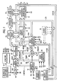
- a composite video signal provided by a source 10 which, may include a conventional television tuner, provides a composite video signal to an analog to digital converter (ADC) 14.
- ADC analog to digital converter
- the ADC 14 digitizes this signal and applies it to a field memory 16.
- the memory 16 is responsive to signals provided by a memory sequencer 18 and by a write address generator 20 to write samples representing image pixels into the field memory 16. These samples are read from the memory 16, after a suitable delay, responsive to address values provided by a read address generator 22.
- the sampled data composite video signal provided by the memory 16 is separated into luminance (Y) and chrominance (C) signal components by YJC separation circuitry 27.
- the luminance and chrominance components are applied to respective vertical interpolator circuits 28 and 32.
- the interpolators 28 and 32 insert additional lines between the lines of the respective video signals provided by the circuitry 27 to effect the requested vertical magnification.
- the chrominance vertical interpolator 32 also separates the chrominance signal into in-phase (I') and quadrature-phase (0') color difference signal components.
- the vertically interpolated luminance signal is applied to hanging dot correction circuitry 29 which removes distorting signal artifacts, introduced in the Y/C separation process, to produce an output signal Y.
- the signal Y is applied to a luminance signal horizontal interpolator 30 and the signals I and Q are applied to a color difference signal horizontal interpolator 34.
- the interpolators 30 and 34 insert interpolated samples between the samples of the respective signals Y and I Q' to effect the horizontal magnification requested by the viewer.
- the portion of the video signal provided by the source 10 which is to be used to produce the magnified image is defined by three signals provided via viewer controls 24, indicated in phantom. These signals are a vertical position value, VPOS, a horizontal position value, HPOS and a zoom ratio value, ZR.
- the signals VPOS and HPOS respectively define a line interval of the video field held in the memory 16 and a sample in that line interval which are at the upper left corner of the image to be magnified.
- the signal ZR defines the magnification factor to be used. This value is not, itself a magnification factor but the denominator of a fraction 256/ZR which is the magnification factor.
- the signal VPOS and ZR are used by the read address generator 22 while the signals HPOS and ZR are used by the horizontal interpolators 30 and 34 to produce the magnified image.
- both starting addresses HPOS and VPOS will be applied to the read address circuitry.
- a signal ZR or a signal representing the desired magnification will be coupled to the read address circuitry to establish the rate at which read addresses are generated. Nominally only the signal ZR or signals representing ZR will be coupled to the vertical and horizontal interpolators. Note signals representing ZR may be, for example, interpolator coefficients which may be provided by preprogrammed read only memories addressed by the values ZR.
- the viewer controls 24 are replaced by an output controller 25.
- the controller 25 is responsive to viewer controls 23 which allow a user to specify the center of the source portion of an image and a magnification factor to be used to produce an output image.
- the controller 25 converts signals provided by these controls into the signals HPOS, VPOS and ZR.
- the controller 25 ensures that the magnified image includes only active video information, and the signals it produces properly track viewer commands to change the center of the source portion as the source portion is panned around the input field.
- FIGURE 1A is a diagram of an exemplary viewer control 23.
- These controls include vertical up and down center position controls, 51 and 52, respectively, horizontal left and right center position controls, 55 and 56, respectively, and zoom-in and zoom-out step controls 58 and 59, respectively.
- a reset button 57 may also be provided.
- the control buttons 51, 52, 55, and 56 By pressing one of the control buttons 51, 52, 55, and 56, the viewer incrementally changes the horizontal and vertical center positions of the target image.
- the control buttons 58 and 59 By pressing one of the control buttons 58 and 59, the viewer incrementally increases and decreases the applied magnification factor. A constant center position is maintained while the magnification factor is changed. However, this center position may be adjusted if a decrease in magnification would cause a portion of the image beyond the raster boundaries to be displayed.
- the reset button, 57 the viewer may return the displayed image to a preset center position and magnification factor, for example, one to one magnification and centered in the
- the zoom system shown in FIGURE 1 is designed for an exemplary video image having 768 active pixels per horizontal line interval, and 256 active line intervals per field. It is understood that the methodology employed may be used for displays with different numbers of pixels per line interval and different numbers of line intervals per field.
- Ten-bit data values are used to identify a horizontal pixel position. Similarly, eight-bit data values are used to identify the line interval in which a pixel resides.
- interstitial pixel values may be interpolated between each pair of contiguous pixels, with a sixteenth position located at the pixel center.
- each pair of horizontal scan lines has 16 interstitial line positions.
- Four additional bits are used to specify the interstitial pixel or line location with the required precision.
- the maximum magnification is attained when each virtual pixel position in the zoom region is mapped to one pixel in the displayed image. This corresponds to 1/65,536th [i.e. 1 /(256 256)] of the original picture being displayed.
- the magnification factor is an eight-bit value, thus, 256 different magnification steps are allowed. Since the most of the steps correspond to non-integer magnification levels, it is convenient to define a zoom ratio signal, ZR, related to the magnification in which each value of the signal ZR corresponds to a unique magnification value and the values of ZR are integers ranging from one to 256.
- magnification factor is defined in terms of the signal ZR by equation (1).
- HPOS is the starting horizontal position
- VPOS is the starting vertical position
- HC is the horizontal center
- VC is the vertical center
- ZR is the selected zoom ratio
- NHP is the number of pixels in a horizontal scan line
- NVL is the number of vertical lines in the display
- NIP is the number of interstitial positions between any two lines or any two pixels, plus one.
- the output controller 25 includes circuitry which automatically corrects the center point of the viewed region so that raster boundaries are not crossed and only active video is displayed. If the magnification factor, MF, is increased while the center point of the magnified image is held at the center of the source image, only active video information will be displayed. However, once the center point of the generated image is moved away from the center of the source image, demagnification may eventually result in the display of non-active video information, i.e. the horizontal and vertical blanking intervals.
- FIGURE 2 is a block diagram showing components of an output controller 25 suitable for use in a first embodiment of the invention.
- This controller accepts the incremental signals provided by the viewer controls 23 and produces signals ZR, HPOS and VPOS for application to the zoom system as shown in FIGURE 1.
- the output controller 25 accepts up and down incremental zoom control signals from the viewer controls 58 and 59, respectively. These control signals are applied to a zoom controller 212 which converts the signals into pulses that respectively decrement and increment the value held in an 8 bit up-down counter 213.
- the output signal of the counter 213 is the signal ZR.
- the horizontal center controller 216 accepts left and right control signals provided by the viewer controls 55 and 56. These signals are converted into pulse signals which respectively decrement and increment a horizontal center counter 217.
- the output signal provided by the counter 217 is the horizontal center signal, HC.
- a vertical center controller 221 receives up and down control signals from the viewer controls 51 and 52.
- the controller 221 converts these signals into pulse signals which respectively decrement and increment a vertical center counter 222.
- the output signal of the counter 222 is the vertical center signal, VC.
- Circuitry which includes an adder 241, multipliers 242 and 243, digital value sources 241 a, 242a and 243a and a subtracter 244 produce the signal HPOS at the output port of the subtracter 244 according to the equation (4) set forth above.
- the adder 241, the multiplier 242, digital value sources 241 a and 242a and a subtracter 248 produce the signal VPOS at the output port of the subtracter 248 according to the equation (5) set forth above.
- the signal HPOS is compared, in a comparator 218, to a signal HL which is defined by equation (10).
- the signal HL is generated by a subtracter 245, multipliers 246 and 247 and digital value sources 245a, 246a, and 247a.
- the signal HL defines the right pixel limiting value for the image. If HPOS is greater than HL, a portion of the horizontal blanking interval will be displayed on the right side of the reproduced image. The left pixel limiting value for the image is zero.
- the comparator 218 performs the validity check set forth above in reference to equation (8) when equation (2) is used to convert the signal HC to the signal HPOS.
- the comparator 218 When the comparator 218 detects that the signal HPOS is greater than HL or less than zero, it applies a logic-one signal to the horizontal center controller 216.
- the controller 216 is also coupled to receive a signal, 225, provided by the counter 217.
- the signal 225 indicates whether the value of the signal HC is on the left or right of horizontal center of the source image, that is to say, whether the value of the signal HC is respectively less than or not less than 6144 (1800 hexadecimal).
- the signal 225 may be generated as the logical OR of the most significant bit (MSB) of the 14-bit signal HC with the logical AND of the next two less significant bits of the signal HC.
- the horizontal center controller 216 conditions the counter 217 to increment its value if HPOS is invalid and HC is in the left half of the source image and to decrement its value if HPOS is invalid and HC is in the if the right half of the source image. Otherwise, the controller 216 increments or decrements the counter 217 as requested by the viewer.
- the subtracter 245, multiplier 246 and digital value sources 245a and 246a are used to generate a vertical limiting signal, VL, which is defined by equation (11).
- the signal VL represents the largest line number or interpolated line number which can be at the top of an image for a given zoom ratio.
- the vertical position signal VPOS is compared to the signal VL by a comparator 223.
- the comparator 223 provides a logic-one output signal when the signal VPOS is greater than VL or when it is less than zero.
- the output signal of the comparator 223 is a logic-zero otherwise.
- the output signal of the comparator 223 is coupled to the vertical center controller 221.
- the controller 221 is also coupled to receive a signal 226 from the counter 222 which indicates that the signal VC represents a line in the upper or lower half of the source image.
- This signal has a logic-one value, for example, when the signal VC is greater than 2048 (800 hexadecimal) and a logic-zero value when the signal VC is less than or equal to 2048.
- the signal 226 may be, for example, the most MSB of the signal VC.
- the vertical center controller 221 conditions the counter 222 to respectively increment or decrement its value.
- the controller 221 conditions the counter 222 to increment or decrement its value as requested by the viewer.
- FIGURE 3 shows the details of a portion of an alternative output controller 23 which may be used to replace step control 212 and 8-bit counter 213, shown in FIGURE 2.
- the only zoom control option for the viewer was to request an increase or a decrease in the value of ZR.
- FIGURE 3 shows a circuit which will allow a user to change ZR or to reset ZR to a predetermined value. Switching to an absolute ZR value allows an instantaneous transition from one magnification factor to another without stepping through the intermediate magnification factors. A typical use for such a feature would be to implement a reset feature as discussed above in reference to the reset button 57 of the viewer controls 23.
- a reset may be achieved by setting the signal ZR to 255.
- This reset button may also be coupled to condition the horizontal and vertical control circuitry to set HPOS and VPOS to zero, as shown below in reference to FIGURES 5A and 5B.
- FIGURE 3 shows a circuit which receives a signal DZ indicating a requested change in the magnification factor.
- This signal is generated, for example, by viewer manipulation of the magnification step controls 58 and 59.
- a value of -1 is provided when the control button 58 is pressed to increase the magnification factor and a value of + 1 is provided when the control button 59 is pressed to decrease the magnification factor.
- the signal DZ is added to the zoom ratio signal ZR by an adder 310.
- the sum provided by the adder 310 is a user requested zoom ratio, Z2.
- the signal Z2 is applied to a Limiter 311 which ensures that the requested value of ZR is within range and corrects the value as necessary.
- the limiter may be eliminated since the signal ZR is kept within these limits by virtue of it being an eight-bit signal. It may be desirable to limit the lower value of the signal ZR to a -value such as 51, to limit the maximum magnification factor to five. In this instance, the limiter 311 would establish a lower limit of 51 for the signal provided by the adder 310.
- the signal Z3, provided by the limiter 311, is applied to one input port of a multiplexor 312.
- An absolute value, A1 for the signal ZR is applied to another input port of the multiplexor 312.
- the control input terminal of the multiplexor is coupled to receive an absolute/differential mode signal ADM1.
- the signal ADM1 may be provided, for example, by the reset control button 57 of the viewer controls 23, shown in FIGURE 1A.
- the multiplexor 312 passes either the signal Z3 or the value A1.
- the multiplexor 312 applies its output signal Z4 to a synchronizing latch 313.
- the latch 313 synchronizes the signal Z4 to the system clock signal (not shown).
- the output signal of the latch 313 is the zoom ratio signal, ZR, which is provided by the output controller 25 as shown in FIGURE 1.
- the signal ZR is also applied to the adder 310, for use in processing further zoom changes, and it is passed on to latch 314 and to one input port of a subtractor 315.
- the latch 314 is a delay element which provides a delay of one cycle of the viewer control update clock. Typically, this clock is relatively slow, having a period on the order of a centisecond to allow the viewer to stop the zoom at any level.
- FIGURE 4 shows a circuit which corrects user requested changes to the signals HPOS and VPOS to account for changes in the zoom ratio signal ZR.
- the signal Z6 is stored in a synchronizing latch 415.
- the output signal, Z7, of latch 415 is applied to two parallel circuits which determine the adjustments to the signals HPOS and VPOS, respectively.
- This circuitry maintains a substantially constant image center position when the magnification factor is changed.
- the signal Z7 is multiplied by 24 by a shift-and-add circuitry which includes bit-shifters 416 and 418 and an adder 417.
- the signal provided by the shifter 418 is subtracted, by a subtractor 419, from a requested horizontal differential signal, DX, to produce a corrected horizontal differential value DX'.
- a subtractor 421 subtracts a signal representing eight times the signal Z7 from a requested vertical differential circuit DY to produce a corrected differential circuit DY .
- the resulting differential horizontal and vertical signals are applied to circuitry such as that shown in FIGURES 5A and 5B which generates the respective signals HPOS and VPOS for the zoom system shown in FIGURE 1.
- FIGURE 5A shows the details of a viewer control interface which may be used to replace the horizontal center controller 216 and the horizontal center counter 217, described above in reference to FIGURE 2. This circuit allows a user either to increment or decrement the signal HC or to substitute an absolute HC value for the current HC signal.
- FIGURE 5B shows circuitry of the same type which performs the same functions for the vertical center signal VC.
- the signal DX' provided by the adder 419 of FIGURE 4 is applied to one input port of an adder 512.
- Another input port of the adder 512 is coupled to receive the signal HPOS.
- the output signal of the adder 512 is a user requested horizontal position signal, X3.
- the signal X3 is range checked in a limiter 513.
- the limiter 513 ensures that the new sum is non-negative and no greater than the total number of pixels and interstitial pixels in a scan line (i.e. 12288).
- the output signal, X4, of limiter 513 is applied to one input port of a multiplexor 514.
- Another input port of the multiplexor 514 is coupled to receive an absolute horizontal position value, A2.
- the multiplexor 514 is conditioned by a control signal ADM2, which may be the same as the signal ADM1, to pass either the signal X4 or a preset ' absolute value, A2.
- the output signal, X5, of the multiplexor 514 is stored in a synchronizing latch 515.
- the output signal of the latch 515 is the signal HPOS which is applied to the zoom circuitry by the output controller 25 as shown in FIGURE 1.
- the signal HPOS is also applied to the adder 512, as set forth above.
- the circuit in FIGURE 5B is substantially the same as the circuit shown in FIGURE 5A.
- the two circuits differ only in the maximum values used by respective limiters 513 and 517.
- the limiter 517 will allow VPOS values as large as the total number of scan lines and interstitial scan lines (i.e. 4096).
- FIGURE 6 shows the details of circuitry which will limit the user requested HPOS and VPOS values, provided by the circuitry shown in FIGURES 5A and 5B, to prevent the display of video information outside of the active video region.
- This circuitry receives, as inputs, the signals ZR, HPOS and VPOS provided by the circuitry shown in FIGURES 3, 4, 5A and 5B.
- the output signals provided by the circuitry shown in FIGURE 6 are corrected signals HPOS and VPOS. These signals are applied to the zoom system shown in FIGURE 1 as the starting horizontal and vertical position signals.
- This circuitry uses substantially the same algorithm as is used by the circuitry shown in FIGURE 2: it limits HPOS to be greater than zero and less than 48 * (256 - ZR). It also limits VPOS to be greater than zero and less than 16 * (256 - ZR).
- FIGURE 6 a zero is concatenated onto the signal ZR in the MSB position to add a ninth bit.
- This new MSB is inverted in inverter 611, and then concatenated to the eight least significant bits (LSB's) of the signal ZR, which have not been inverted.
- LSB's least significant bits
- This operation is equivalent to a twos complement subtraction of 256 from ZR.
- the difference value produced by this operation is applied to a conventional shift and add multiplier 612 which multiplies the difference value by three.
- the multiplier 612 includes a synchronizing latch (not shown).
- the output signal of the multiplier 612 is a ten-bit signal. Four zero bits are concatenated to this value in the LSB positions to provide a 14 bit value, P5, which represents the signal provided by the multiplier 612 multiplied by 16.
- the signal P5 is extended to 15 bits by sign extending circuitry 613 which adds a fifteenth most significant bit with the same value as the fourteenth (previously the most significant) bit.
- This 15-bit signal, P6 is applied to an input port of an adder 614.
- Another input port of the adder 614 is coupled to receive a signal S5 which is the signal HPOS extended to 15 bits and delayed by a synchronizing latch 619 to be properly timed with respect to the signal P6.
- the signals S5 and P6 are summed by adder 614, yielding a signal, S6.
- the signal S6 has a value of [HPOS + 48 * (ZR - 256)] which is equivalent to -[48 * (256 - ZR) - HPOS].
- the product in the square brackets is essentially the same limiting signal that is applied to the comparator 218 in FIGURE 2.
- the 15 bits of the signal S6 are applied to respective first input terminals of a 15 two-input NAND gates 615. An inverted version of the MSB of the signal S6 is applied to the second input terminal of each of the gates 615.
- each of the 15 bits will be inverted so that the signal S7 provided by the NAND gates 615 is the ones complement representation of the signal S6. If, however, the MSB of the signal S6 is logic-one (a negative S6), the NAND gates 615 are all disabled and provide an output value having 15 ones (the ones complement of zero).
- the signal S7 is applied, through a synchronizing latch 619, to one input port of an adder 616.
- the other input port of the adder 616 is coupled to receive the signal S5 via a synchronizing latch 620.
- the adder 616 has a carry-in input terminal, Cl, which is coupled to receive a logic-one value. In this configuration, the adder 616 effectively converts the ones complement values provided by the latch 619 into twos complement negative values which are added to the twos complement positive values provided by the latch 620.
- This operation subtracts the signal S6 from the signal S5. If S6 is negative or zero then the signal HPOS is within its valid range and a value of zero is subtracted from HPOS by the adder 616. If S6 is positive, its value is the amount by which the signal HPOS exceeds its upper limit. This value is subtracted by the adder 616 to produce a signal HPOS that is within its upper limit. However, the signal HPOS may still be less than the lower limit of zero. HPOS is limited to be within its lower limit (i.e. to be greater than or equal to zero) by a bank of 14 AND gates, 617. First input terminals of the gates 617 are coupled to receive the 14 LSB's, respectively, of the signal provided by the adder 616.
- Second input terminals of each of the AND gates 617 are coupled to receive an inverted version of the MSB (i.e. the sign bit) of the signal provided by the adder 616.
- the AND gates 617 are disabled and provide a zero value. Otherwise, the gates 617 pass the value applied to their first input terminals.
- the output signal provided by the AND gates 617 is passed through a synchronizing latch 618 to produce a signal HPOS .
- This signal is the horizontal position signal that is provided to the zoom circuitry shown in FIGURE 1.
- the signal S4 i.e.the signal (ZR - 256) is multiplied by 16 by the concatenation of four logic-zero valued LSBs from a digital value source 630a.
- This product, the signal P7, is applied to a synchronizing latch 630.
- the user requested vertical center value, VPOS is applied to a synchronizing latch 641.
- the 12-bit output signal of the latch 641 is extended to 13 bits by concatenating a logic-zero in the thirteenth most significant bit position. This 13 bit version of the signal VPOS is designated S10.
- the signal S10 is added to the signal provided by the latch 630 by an adder 632.
- the output signal, S11, of the adder 632 has a value represented by the expression [VPOS + 16 * (ZR -256)]. If S11 is positive, its value represents an error in the upper bound of the signal VPOS. If S11 is negative or zero there is no error. Accordingly, the signal SII is limited to be zero or positive by a bank of 13 NAND gates 633 and subtracted from the signal VPOS by an adder 635.
- the adder 635 is configured in the same way as the adder 616 described above.
- the output signal S13 provided by the adder 635 is a VPOS signal that is limited to be within its upper bound.
- the signal VPOS is limited to be within its lower bound (i.e. greater than zero) by a bank of 12 AND gates 636.
- the output signal provided by the AND gates 636 is applied to a synchronizing latch 637 which provides the fully limited signal VPOS . This signal is the vertical position signal that is applied to the zoom system shown in FIGURE 1.
- the signals HPOS' and VPOS', provided by the circuitry shown in FIGURE 6, are limited to produce a magnified image that is always entirely within the active video region.
- FIGURES 7 through 10 illustrate a third embodiment of the present invention.
- the horizontal and vertical center positions are adjusted by a microprocessor 712 as incremental changes are requested using the viewer controls 23.
- the horizontal and vertical center positions are stored and manipulated as eight-bit values. These values are converted into respective 14 and 12 bit starting pixel values, HPOS and VPOS, respectively, which are applied to the zoom system shown in FIGURE 1.
- HPOS and VPOS starting pixel values
- the microprocessor 712 also adjusts the magnification factor by incrementing or decrementing the zoom ratio signal, ZR.
- the magnification factor is limited to a range between one-to-one and five-to-one.
- the horizontal and vertical center positions are reevaluated to determine if further adjustment of these signals is desirable to prevent the display of the blanking intervals.
- An assembly language listing of the program which controls the microprocessor 712 is included as an appendix to this specification.
- the program is written in assembly language for a HD63B01 YO microprocessor manufactured by Hitachi, Inc.
- the viewer control buttons, 51, 52, 55, 56, 58 and 59 are coupled to interface circuitry 710.'This circuitry translates the action of the viewer pressing one or more of the buttons into a sequence of commands for a microprocessor 712.
- the operator control 23 is a remote control transmitter and
- the interface 710 is circuitry internal to the remote control transmitter, which generates a sequence of infra-red signals, and circuitry internal to the television receiver, which translates these signals into commands for the microprocessor 712.
- the microprocessor 712 interprets these incremental commands to produce signals ZR, HPOS and VPOS for application to the zoom system shown in FIGURE 1.
- the signals ZR, HPOS and VPOS are stored, by the microprocessor 712, in respective latches 714, 716 and 718 as they are calculated.
- FIGURE 8 is a flow-chart diagram of an exemplary main program which is executed by the microprocessor 712 to generate the signals ZR, HPOS and VPOS.
- commands are received from the interface 710 at step 810.
- Step 812 determines if the command is an adjustment of the signal ZR. If so, it invokes a zoom routine at step 818. If the command is not a zoom adjustment, step 812 transfers control to step 814 which invokes a horizontal position routine, at step 820, if the command is for a horizontal center position adjustment. If so, the command is neither a zoom change nor a horizontal position change step, control passes to step 816 which determines if the command is a vertical center adjustment.
- the command 816 invokes a vertical position routine at step 822. If the command was not a vertical center adjustment command, control is transferred to the step 810 to await the next command. After the routines invoked at the steps 818, 820 and 822 have returned control to the main program, the step 810 is executed to await the next command.
- FIGURE 9 is a flow-chart diagram of an exemplary horizontal position routine.
- This routine begins at step 900 which receives the command from the main program.
- Step 910 tests the type of the received command to determine if it is an increment command or a decrement command. If it is an increment command, step 912 is executed which adds a value of one to an eight-bit horizontal center position variable HC. If the command is a decrement command, step 914 is executed which subtracts a value of one from the variable HC.
- the steps 912 and 914 both transfer control to a step 916.
- the step 916 determines if the value held by the variable HC is less than the quantity ZR/2. If it is, then the left side of the magnified image may include portions of the horizontal blanking interval. To prevent this, step 918 is executed which assigns the value ZR/2 to the variable HC. The next step executed, 920, determines if the value held in the variable HC is greater than 256- ZR/2. If so, the right side of the image may include portions of the horizontal blanking interval. To prevent this, the step 922 is executed which assigns the value 256 - ZR/2 to the variable HC.
- the next step, 924 multiplies the value held in HC by 64 and stores the result in a variable HC1. This operation converts the eight-bit HC value into an equivalent 14-bit value. Step 924 also generates a horizontal starting position value from the value HC1 and stores the generated value in a variable HPOS. The algorithm for this conversion is given in the equation (4) set forth above.
- the value HPOS is applied by the microprocessor 712 to the latch 716.
- the final step, 928, of the routine returns control to the program which invoked the horizontal position routine.
- the vertical position routine is the same as the horizontal position routine shown in FIGURE 9 except that the variables VC, VC1 and VPOS replace the variables HC, HC1 and HPOS, the step 924 multiplies VC by 16 instead of 64, and equation (5) is used instead of equation (4) to convert the value held in VC1 to a value to be stored in VPOS.
- FIGURE 10 is a flow-chart diagram of a zoom routine suitable for use in this embodiment of the invention.
- the zoom routine starts at step 1000 which accepts the command from the interface 710.
- Step 1010 determines if the command requests that the signal ZR be incremented (to reduce the magnification factor) or be decremented (to increase the magnification factor). If ZR is to be incremented, step 1012 is executed, otherwise step 1014 is executed.
- the next step in the routine, 1016 determines if the value held in the variable ZR is less than 51. This value corresponds to a magnification factor of five-to-one, an arbitrarily established maximum for this embodiment of the invention. If ZR is less than 51, a step 1018 sets ZR to 51.
- Step 1020 determines if the incremented value held in the variable ZR is greater than 256. This value corresponds to the minimum magnification factor, one-to-one. Step 1022 limits the value held in ZR to 256. After the value held in ZR has been updated, the horizontal position routine is invoked at step 1024 and the vertical position routine is invoked at step 1026 to recalculate the current values of HC and VC using the new value of ZR. These recalculated values for HC and VC ensure that image blanking intervals are not displayed as part of the magnified image. Step 1028 writes the calculated values of ZR, HPOS and VPOS into the registers 714, 716 and 718 and step 1030.returns control to the main program.
Abstract
Description
- The present invention relates to image centering apparatus for a zoom and pan video display system.
- U.S. Patent 4,774,581 entitled "Television Picture Zoom System", relates to circuitry that produces a magnified image representing a portion of a video frame from a conventional television signal. The portion of the field which is magnified, hereinafter referred to as the source portion, is determined by signals provided via viewer controls. These controls define the upper left corner of the image, in terms of horizontal and vertical pixel positions in the unmagnified field, and a magnification factor to be used to produce the magnified display.
- In this referenced patent, the upper left corner of the source portion is used as a reference point when the magnification factor is changed or when the source portion is panned around the unmagnified field. However, this may not be the best reference point. Intuitively, a viewer manipulating the controls would expect the center of the image to be the reference point since this is the reference used by mechanical zoom apparatus such as photographic zoom lenses. If, for example, the upper left corner of a source portion were used as the reference point, an object of interest in the center of the picture may be moved out of the display when the magnification factor is increased.
- From the point of view of the circuit designer, it is more convenient to provide the pixel positions of the upper left corner of the portion of the image to be magnified to the zoom and pan system. If, for example, the portion of the image being magnified were near an edge of the frame and the magnification factor were reduced, maintaining a constant center position would cause portions of the video signal outside of the active video region (i.e. the horizontal or vertical blanking intervals) to be included in the magnified display. Moreover, it is easier to determine the allowable limits of the source portion during a pan operation when the upper left corner is used as the reference point than when the image center is used as the reference point.
- The present invention is embodied in apparatus and a method for selecting a part of a field of an input video signal to be used to produce a magnified image. This apparatus includes control circuitry which allows a viewer to select the center position of the selected part, and the magnification factor to be used to produce the magnified image. Monitoring circuitry is included in the apparatus to limit the boundaries of the selected part to be within the active video portion of the input signal. This monitoring circuitry is responsive to the horizontal and vertical coordinates of the selected center position as well as to the selected magnification factor.
-
- FIGURE 1 is a block diagram of a television receiver which includes an image zoom feature.
- FIGURE 1 a is a diagram of a zoom system control suitable for use with the television receiver shown in FIGURE 1.
- FIGURE 2 is a block diagram of an output controller suitable for use in the television receiver shown in FIGURE 1.
- FIGURE 3 is a block diagram of a portion of an alternative output controller which limits the magnification factor selected by the viewer.
- FIGURES 4, 5A and 5B are block diagrams of other portions of the alternative controller which limit the horizontal and vertical starting positions selected by the viewer.
- FIGURE 6 is a block diagram of circuitry which augments the controller shown in FIGURES 3, 4, 5A and 5B.
- FIGURE 7 is a block diagram of a second alternative output controller which limits the magnification factor and vertical and horizontal starting positions selected by the viewer.
- FIGURES 8, 9 and 10 are flow chart diagrams useful for explaining the operation of the controller shown in FIGURE 7.
- The following is a brief description of the zoom system described in the above referenced U.S. Patent 4,774,581 which provides a context for the present invention. In FIGURE 1, a composite video signal, provided by a
source 10 which, may include a conventional television tuner, provides a composite video signal to an analog to digital converter (ADC) 14. TheADC 14 digitizes this signal and applies it to afield memory 16. Thememory 16 is responsive to signals provided by amemory sequencer 18 and by awrite address generator 20 to write samples representing image pixels into thefield memory 16. These samples are read from thememory 16, after a suitable delay, responsive to address values provided by aread address generator 22. - The sampled data composite video signal provided by the
memory 16 is separated into luminance (Y) and chrominance (C) signal components byYJC separation circuitry 27. The luminance and chrominance components are applied to respectivevertical interpolator circuits interpolators circuitry 27 to effect the requested vertical magnification. The chrominancevertical interpolator 32 also separates the chrominance signal into in-phase (I') and quadrature-phase (0') color difference signal components. - The vertically interpolated luminance signal is applied to hanging
dot correction circuitry 29 which removes distorting signal artifacts, introduced in the Y/C separation process, to produce an output signal Y. The signal Y is applied to a luminance signalhorizontal interpolator 30 and the signals I and Q are applied to a color difference signalhorizontal interpolator 34. Theinterpolators - In the above-referenced patent, the portion of the video signal provided by the
source 10 which is to be used to produce the magnified image is defined by three signals provided viaviewer controls 24, indicated in phantom. These signals are a vertical position value, VPOS, a horizontal position value, HPOS and a zoom ratio value, ZR. The signals VPOS and HPOS respectively define a line interval of the video field held in thememory 16 and a sample in that line interval which are at the upper left corner of the image to be magnified. The signal ZR defines the magnification factor to be used. This value is not, itself a magnification factor but the denominator of afraction 256/ZR which is the magnification factor. The signal VPOS and ZR are used by theread address generator 22 while the signals HPOS and ZR are used by thehorizontal interpolators - Those persons skilled in the art of digital video signal processing will readily appreciate that in the more general case both starting addresses HPOS and VPOS will be applied to the read address circuitry. In addition a signal ZR or a signal representing the desired magnification will be coupled to the read address circuitry to establish the rate at which read addresses are generated. Nominally only the signal ZR or signals representing ZR will be coupled to the vertical and horizontal interpolators. Note signals representing ZR may be, for example, interpolator coefficients which may be provided by preprogrammed read only memories addressed by the values ZR.
- In the present embodiments of the invention, the
viewer controls 24 are replaced by anoutput controller 25. Thecontroller 25 is responsive toviewer controls 23 which allow a user to specify the center of the source portion of an image and a magnification factor to be used to produce an output image. Thecontroller 25 converts signals provided by these controls into the signals HPOS, VPOS and ZR. Thecontroller 25 ensures that the magnified image includes only active video information, and the signals it produces properly track viewer commands to change the center of the source portion as the source portion is panned around the input field. - FIGURE 1A is a diagram of an
exemplary viewer control 23. These controls include vertical up and down center position controls, 51 and 52, respectively, horizontal left and right center position controls, 55 and 56, respectively, and zoom-in and zoom-outstep controls reset button 57 may also be provided. By pressing one of thecontrol buttons control buttons - Two different hardware implementations and one combined hardware and software implementation of the
output controller 25 are described below. To understand the operation of these controllers, it is helpful to first understand some mathematics used by the controllers. The zoom system shown in FIGURE 1 is designed for an exemplary video image having 768 active pixels per horizontal line interval, and 256 active line intervals per field. It is understood that the methodology employed may be used for displays with different numbers of pixels per line interval and different numbers of line intervals per field. - Ten-bit data values are used to identify a horizontal pixel position. Similarly, eight-bit data values are used to identify the line interval in which a pixel resides.
- During the zooming process, when the magnification factor is changing, it is desirable to maintain the appearance of a smooth, continuous transition, although the displayed image is changing in discrete steps. As the number of intermediate steps grows larger, the change appears smoother. Moreover, it is desirable to create a relatively large number of virtual positions located between the actual pixels, in order to identify a unique value for each pixel in the magnified display. To these ends, 256 virtual positions are defined between each pair of pixels in a scan line and between each pair of scan lines. These virtual positions are used to define the relative positions of the pixels and lines which constitute the magnified display. However, these virtual positions are grouped into a smaller number of interstitial positions for interpolation. In the embodiments of the invention described below, 15 interstitial pixel values may be interpolated between each pair of contiguous pixels, with a sixteenth position located at the pixel center. Likewise, each pair of horizontal scan lines has 16 interstitial line positions. Four additional bits are used to specify the interstitial pixel or line location with the required precision.
Output controller 25, therefore, specifies HPOS as a 14-bit signal and VPOS as a 12-bit signal. - The maximum magnification is attained when each virtual pixel position in the zoom region is mapped to one pixel in the displayed image. This corresponds to 1/65,536th [i.e. 1 /(256 256)] of the original picture being displayed. The magnification factor is an eight-bit value, thus, 256 different magnification steps are allowed. Since the most of the steps correspond to non-integer magnification levels, it is convenient to define a zoom ratio signal, ZR, related to the magnification in which each value of the signal ZR corresponds to a unique magnification value and the values of ZR are integers ranging from one to 256. To determine the unique zoom ratio value for any magnification level, it is only necessary to determine the fraction of the image, along a linear dimension, which is displayed and multiply by the maximum magnification value (in this case 256). In order to store the information in eight bits, rather than nine, one is subtracted from each value of the signal ZR as per the above computation, making the range of the signal ZR between zero and 255. The magnification factor, MF, is defined in terms of the signal ZR by equation (1).

- Since this magnification factor is applied uniformly across the displayed region, a pair of center point coordinates and a ZR value will uniquely define the horizontal and vertical pixel positions, HPOS and VPOS, of the upper left corner of the image. The general relationship is defined by equations (2) and (3), and the specific relationship for a 768 x 256 display is defined by equations (4) and (5).


- In these equations, HPOS is the starting horizontal position, VPOS is the starting vertical position HC is the horizontal center, VC is the vertical center, ZR is the selected zoom ratio, NHP is the number of pixels in a horizontal scan line. NVL is the number of vertical lines in the display and NIP is the number of interstitial positions between any two lines or any two pixels, plus one.
- In addition to allowing the user to specify a center point and a zoom factor, the
output controller 25 includes circuitry which automatically corrects the center point of the viewed region so that raster boundaries are not crossed and only active video is displayed. If the magnification factor, MF, is increased while the center point of the magnified image is held at the center of the source image, only active video information will be displayed. However, once the center point of the generated image is moved away from the center of the source image, demagnification may eventually result in the display of non-active video information, i.e. the horizontal and vertical blanking intervals. - The general relationship defining the valid horizontal and vertical center positions is given by the inequalities (6) and (7) while the specific relationship for a 768 pixel by 256 line display is given by the inequalities (8) and (9).


- FIGURE 2 is a block diagram showing components of an
output controller 25 suitable for use in a first embodiment of the invention. This controller accepts the incremental signals provided by the viewer controls 23 and produces signals ZR, HPOS and VPOS for application to the zoom system as shown in FIGURE 1. - To change the magnification factor, the
output controller 25 accepts up and down incremental zoom control signals from the viewer controls 58 and 59, respectively. These control signals are applied to azoom controller 212 which converts the signals into pulses that respectively decrement and increment the value held in an 8 bit up-down counter 213. The output signal of thecounter 213 is the signal ZR. - The
horizontal center controller 216 accepts left and right control signals provided by the viewer controls 55 and 56. These signals are converted into pulse signals which respectively decrement and increment ahorizontal center counter 217. The output signal provided by thecounter 217 is the horizontal center signal, HC. - In the same way, a
vertical center controller 221 receives up and down control signals from the viewer controls 51 and 52. Thecontroller 221 converts these signals into pulse signals which respectively decrement and increment avertical center counter 222. The output signal of thecounter 222 is the vertical center signal, VC. - Circuitry which includes an
adder 241,multipliers digital value sources subtracter 244 produce the signal HPOS at the output port of thesubtracter 244 according to the equation (4) set forth above. Similarly, theadder 241, themultiplier 242,digital value sources subtracter 248 produce the signal VPOS at the output port of thesubtracter 248 according to the equation (5) set forth above. - The signal HPOS is compared, in a
comparator 218, to a signal HL which is defined by equation (10).
subtracter 245,multipliers digital value sources comparator 218 performs the validity check set forth above in reference to equation (8) when equation (2) is used to convert the signal HC to the signal HPOS. - When the
comparator 218 detects that the signal HPOS is greater than HL or less than zero, it applies a logic-one signal to thehorizontal center controller 216. Thecontroller 216 is also coupled to receive a signal, 225, provided by thecounter 217. Thesignal 225 indicates whether the value of the signal HC is on the left or right of horizontal center of the source image, that is to say, whether the value of the signal HC is respectively less than or not less than 6144 (1800 hexadecimal). There are 12288 (768 * 16) pixels and interstitial pixels on each line of the source image. Thesignal 225 may be generated as the logical OR of the most significant bit (MSB) of the 14-bit signal HC with the logical AND of the next two less significant bits of the signal HC. - Responsive to these two signals, the
horizontal center controller 216 conditions thecounter 217 to increment its value if HPOS is invalid and HC is in the left half of the source image and to decrement its value if HPOS is invalid and HC is in the if the right half of the source image. Otherwise, thecontroller 216 increments or decrements thecounter 217 as requested by the viewer. - The
subtracter 245,multiplier 246 anddigital value sources 
comparator 223. - The
comparator 223 provides a logic-one output signal when the signal VPOS is greater than VL or when it is less than zero. the output signal of thecomparator 223 is a logic-zero otherwise. The output signal of thecomparator 223 is coupled to thevertical center controller 221. Thecontroller 221 is also coupled to receive asignal 226 from thecounter 222 which indicates that the signal VC represents a line in the upper or lower half of the source image. This signal has a logic-one value, for example, when the signal VC is greater than 2048 (800 hexadecimal) and a logic-zero value when the signal VC is less than or equal to 2048. There are 4096 (256 * 16) lines and interstitial lines in a field of the source image. Thesignal 226 may be, for example, the most MSB of the signal VC. - When the
comparator 223 indicates that VPOS is invalid and thesignal 226 indicates that the current vertical center is in the upper half or the lower half of the source image, thevertical center controller 221 conditions thecounter 222 to respectively increment or decrement its value. When thecomparator 223 indicates that VPOS is valid, thecontroller 221 conditions thecounter 222 to increment or decrement its value as requested by the viewer. - FIGURE 3 shows the details of a portion of an
alternative output controller 23 which may be used to replacestep control 212 and 8-bit counter 213, shown in FIGURE 2. In the discussion of the previous embodiment of the invention, the only zoom control option for the viewer was to request an increase or a decrease in the value of ZR. FIGURE 3 shows a circuit which will allow a user to change ZR or to reset ZR to a predetermined value. Switching to an absolute ZR value allows an instantaneous transition from one magnification factor to another without stepping through the intermediate magnification factors. A typical use for such a feature would be to implement a reset feature as discussed above in reference to thereset button 57 of the viewer controls 23. In these embodiments of the invention, a reset may be achieved by setting the signal ZR to 255. This reset button may also be coupled to condition the horizontal and vertical control circuitry to set HPOS and VPOS to zero, as shown below in reference to FIGURES 5A and 5B. - FIGURE 3 shows a circuit which receives a signal DZ indicating a requested change in the magnification factor. This signal is generated, for example, by viewer manipulation of the magnification step controls 58 and 59. A value of -1 is provided when the
control button 58 is pressed to increase the magnification factor and a value of + 1 is provided when thecontrol button 59 is pressed to decrease the magnification factor. The signal DZ is added to the zoom ratio signal ZR by anadder 310. The sum provided by theadder 310 is a user requested zoom ratio, Z2. The signal Z2 is applied to aLimiter 311 which ensures that the requested value of ZR is within range and corrects the value as necessary. For the range of the signal ZR set forth above (0 to 255), the limiter may be eliminated since the signal ZR is kept within these limits by virtue of it being an eight-bit signal. It may be desirable to limit the lower value of the signal ZR to a -value such as 51, to limit the maximum magnification factor to five. In this instance, thelimiter 311 would establish a lower limit of 51 for the signal provided by theadder 310. - The signal Z3, provided by the
limiter 311, is applied to one input port of amultiplexor 312. An absolute value, A1, for the signal ZR is applied to another input port of themultiplexor 312. The control input terminal of the multiplexor is coupled to receive an absolute/differential mode signal ADM1. The signal ADM1 may be provided, for example, by thereset control button 57 of the viewer controls 23, shown in FIGURE 1A. Responsive to the signal ADM1, the multiplexor 312 passes either the signal Z3 or the value A1. Themultiplexor 312 applies its output signal Z4 to a synchronizinglatch 313. Thelatch 313 synchronizes the signal Z4 to the system clock signal (not shown). The output signal of thelatch 313 is the zoom ratio signal, ZR, which is provided by theoutput controller 25 as shown in FIGURE 1. - The signal ZR is also applied to the
adder 310, for use in processing further zoom changes, and it is passed on to latch 314 and to one input port of asubtractor 315. In this embodiment of the invention, thelatch 314 is a delay element which provides a delay of one cycle of the viewer control update clock. Typically, this clock is relatively slow, having a period on the order of a centisecond to allow the viewer to stop the zoom at any level. By subtracting the signal Z5 from the signal ZR, the zoom differential, Z6, between the current and previous values of the signal ZR may be determined. The .signal Z6 may differ from the user requested zoom differential signal Z1 if thelimiter 311 has made adjustments or if the system has been reset. The zoom differential signal, Z6, is used in the circuit shown in FIGURE 4 to adjust the values of the signals HPOS and VPOS. - FIGURE 4 shows a circuit which corrects user requested changes to the signals HPOS and VPOS to account for changes in the zoom ratio signal ZR. The signal Z6 is stored in a synchronizing
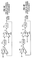
latch 415. The output signal, Z7, oflatch 415 is applied to two parallel circuits which determine the adjustments to the signals HPOS and VPOS, respectively. This circuitry maintains a substantially constant image center position when the magnification factor is changed. The signal Z7 is multiplied by 24 by a shift-and-add circuitry which includes bit-shifters adder 417. The signal provided by theshifter 418 is subtracted, by asubtractor 419, from a requested horizontal differential signal, DX, to produce a corrected horizontal differential value DX'. In the same manner, asubtractor 421 subtracts a signal representing eight times the signal Z7 from a requested vertical differential circuit DY to produce a corrected differential circuit DY . The resulting differential horizontal and vertical signals are applied to circuitry such as that shown in FIGURES 5A and 5B which generates the respective signals HPOS and VPOS for the zoom system shown in FIGURE 1. - FIGURE 5A shows the details of a viewer control interface which may be used to replace the
horizontal center controller 216 and thehorizontal center counter 217, described above in reference to FIGURE 2. This circuit allows a user either to increment or decrement the signal HC or to substitute an absolute HC value for the current HC signal. FIGURE 5B shows circuitry of the same type which performs the same functions for the vertical center signal VC. - In the circuitry shown in FIGURE 5A, the signal DX', provided by the
adder 419 of FIGURE 4 is applied to one input port of anadder 512. Another input port of theadder 512 is coupled to receive the signal HPOS. The output signal of theadder 512 is a user requested horizontal position signal, X3. The signal X3 is range checked in alimiter 513. Thelimiter 513 ensures that the new sum is non-negative and no greater than the total number of pixels and interstitial pixels in a scan line (i.e. 12288). The output signal, X4, oflimiter 513 is applied to one input port of amultiplexor 514. Another input port of themultiplexor 514 is coupled to receive an absolute horizontal position value, A2. Themultiplexor 514 is conditioned by a control signal ADM2, which may be the same as the signal ADM1, to pass either the signal X4 or a preset' absolute value, A2. The output signal, X5, of themultiplexor 514 is stored in a synchronizinglatch 515. The output signal of thelatch 515 is the signal HPOS which is applied to the zoom circuitry by theoutput controller 25 as shown in FIGURE 1. The signal HPOS is also applied to theadder 512, as set forth above. The circuit in FIGURE 5B is substantially the same as the circuit shown in FIGURE 5A. The two circuits differ only in the maximum values used byrespective limiters limiter 517 will allow VPOS values as large as the total number of scan lines and interstitial scan lines (i.e. 4096). - FIGURE 6 shows the details of circuitry which will limit the user requested HPOS and VPOS values, provided by the circuitry shown in FIGURES 5A and 5B, to prevent the display of video information outside of the active video region. This circuitry receives, as inputs, the signals ZR, HPOS and VPOS provided by the circuitry shown in FIGURES 3, 4, 5A and 5B. The output signals provided by the circuitry shown in FIGURE 6 are corrected signals HPOS and VPOS. These signals are applied to the zoom system shown in FIGURE 1 as the starting horizontal and vertical position signals. This circuitry uses substantially the same algorithm as is used by the circuitry shown in FIGURE 2: it limits HPOS to be greater than zero and less than 48 * (256 - ZR). It also limits VPOS to be greater than zero and less than 16 * (256 - ZR).
- In FIGURE 6, a zero is concatenated onto the signal ZR in the MSB position to add a ninth bit. This new MSB is inverted in
inverter 611, and then concatenated to the eight least significant bits (LSB's) of the signal ZR, which have not been inverted. This operation is equivalent to a twos complement subtraction of 256 from ZR. The difference value produced by this operation is applied to a conventional shift and addmultiplier 612 which multiplies the difference value by three. Themultiplier 612 includes a synchronizing latch (not shown). The output signal of themultiplier 612 is a ten-bit signal. Four zero bits are concatenated to this value in the LSB positions to provide a 14 bit value, P5, which represents the signal provided by themultiplier 612 multiplied by 16. - The signal P5 is extended to 15 bits by
sign extending circuitry 613 which adds a fifteenth most significant bit with the same value as the fourteenth (previously the most significant) bit. This 15-bit signal, P6, is applied to an input port of anadder 614. Another input port of theadder 614 is coupled to receive a signal S5 which is the signal HPOS extended to 15 bits and delayed by a synchronizinglatch 619 to be properly timed with respect to the signal P6. - The signals S5 and P6 are summed by
adder 614, yielding a signal, S6. The signal S6 has a value of [HPOS + 48 * (ZR - 256)] which is equivalent to -[48 * (256 - ZR) - HPOS]. The product in the square brackets is essentially the same limiting signal that is applied to thecomparator 218 in FIGURE 2. The 15 bits of the signal S6 are applied to respective first input terminals of a 15 two-input NAND gates 615. An inverted version of the MSB of the signal S6 is applied to the second input terminal of each of thegates 615. If the MSB is logic-zero (a positive S6), each of the 15 bits will be inverted so that the signal S7 provided by theNAND gates 615 is the ones complement representation of the signal S6. If, however, the MSB of the signal S6 is logic-one (a negative S6), theNAND gates 615 are all disabled and provide an output value having 15 ones (the ones complement of zero). - The signal S7 is applied, through a synchronizing
latch 619, to one input port of anadder 616. The other input port of theadder 616 is coupled to receive the signal S5 via a synchronizinglatch 620. Theadder 616 has a carry-in input terminal, Cl, which is coupled to receive a logic-one value. In this configuration, theadder 616 effectively converts the ones complement values provided by thelatch 619 into twos complement negative values which are added to the twos complement positive values provided by thelatch 620. - This operation subtracts the signal S6 from the signal S5. If S6 is negative or zero then the signal HPOS is within its valid range and a value of zero is subtracted from HPOS by the
adder 616. If S6 is positive, its value is the amount by which the signal HPOS exceeds its upper limit. This value is subtracted by theadder 616 to produce a signal HPOS that is within its upper limit. However, the signal HPOS may still be less than the lower limit of zero. HPOS is limited to be within its lower limit (i.e. to be greater than or equal to zero) by a bank of 14 AND gates, 617. First input terminals of thegates 617 are coupled to receive the 14 LSB's, respectively, of the signal provided by theadder 616. Second input terminals of each of the ANDgates 617 are coupled to receive an inverted version of the MSB (i.e. the sign bit) of the signal provided by theadder 616. When the signal provided by theadder 616 is negative, the ANDgates 617 are disabled and provide a zero value. Otherwise, thegates 617 pass the value applied to their first input terminals. - The output signal provided by the AND
gates 617 is passed through a synchronizinglatch 618 to produce a signal HPOS . This signal is the horizontal position signal that is provided to the zoom circuitry shown in FIGURE 1. - A similar correction is applied to the signal VPOS. The signal S4 (i.e.the signal (ZR - 256) is multiplied by 16 by the concatenation of four logic-zero valued LSBs from a
digital value source 630a. This product, the signal P7, is applied to a synchronizinglatch 630. The user requested vertical center value, VPOS, is applied to a synchronizinglatch 641. The 12-bit output signal of thelatch 641 is extended to 13 bits by concatenating a logic-zero in the thirteenth most significant bit position. This 13 bit version of the signal VPOS is designated S10. The signal S10 is added to the signal provided by thelatch 630 by anadder 632. - The output signal, S11, of the
adder 632 has a value represented by the expression [VPOS + 16 * (ZR -256)]. If S11 is positive, its value represents an error in the upper bound of the signal VPOS. If S11 is negative or zero there is no error. Accordingly, the signal SII is limited to be zero or positive by a bank of 13NAND gates 633 and subtracted from the signal VPOS by anadder 635. Theadder 635 is configured in the same way as theadder 616 described above. The output signal S13 provided by theadder 635 is a VPOS signal that is limited to be within its upper bound. The signal VPOS is limited to be within its lower bound (i.e. greater than zero) by a bank of 12 ANDgates 636. The output signal provided by the ANDgates 636 is applied to a synchronizinglatch 637 which provides the fully limited signal VPOS . This signal is the vertical position signal that is applied to the zoom system shown in FIGURE 1. - The signals HPOS' and VPOS', provided by the circuitry shown in FIGURE 6, are limited to produce a magnified image that is always entirely within the active video region.
- FIGURES 7 through 10 illustrate a third embodiment of the present invention. In this system, the horizontal and vertical center positions are adjusted by a
microprocessor 712 as incremental changes are requested using the viewer controls 23. The horizontal and vertical center positions are stored and manipulated as eight-bit values. These values are converted into respective 14 and 12 bit starting pixel values, HPOS and VPOS, respectively, which are applied to the zoom system shown in FIGURE 1. Using this method, the value of HPOS is adjusted in increments of three pixels of the source image and the value of VPOS is adjusted in increments of one scan line of the source image. Themicroprocessor 712 also adjusts the magnification factor by incrementing or decrementing the zoom ratio signal, ZR. The magnification factor is limited to a range between one-to-one and five-to-one. When the signal ZR is adjusted, the horizontal and vertical center positions are reevaluated to determine if further adjustment of these signals is desirable to prevent the display of the blanking intervals. - An assembly language listing of the program which controls the
microprocessor 712 is included as an appendix to this specification. The program is written in assembly language for a HD63B01 YO microprocessor manufactured by Hitachi, Inc. - In FIGURE 7, the viewer control buttons, 51, 52, 55, 56, 58 and 59 are coupled to interface circuitry 710.'This circuitry translates the action of the viewer pressing one or more of the buttons into a sequence of commands for a
microprocessor 712. In the present embodiment of the invention, theoperator control 23 is a remote control transmitter and The interface 710 is circuitry internal to the remote control transmitter, which generates a sequence of infra-red signals, and circuitry internal to the television receiver, which translates these signals into commands for themicroprocessor 712. - The
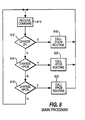
microprocessor 712 interprets these incremental commands to produce signals ZR, HPOS and VPOS for application to the zoom system shown in FIGURE 1. The signals ZR, HPOS and VPOS are stored, by themicroprocessor 712, inrespective latches - FIGURE 8 is a flow-chart diagram of an exemplary main program which is executed by the
microprocessor 712 to generate the signals ZR, HPOS and VPOS. In FIGURE 8, commands are received from the interface 710 atstep 810. Step 812 determines if the command is an adjustment of the signal ZR. If so, it invokes a zoom routine atstep 818. If the command is not a zoom adjustment, step 812 transfers control to step 814 which invokes a horizontal position routine, atstep 820, if the command is for a horizontal center position adjustment. If so, the command is neither a zoom change nor a horizontal position change step, control passes to step 816 which determines if the command is a vertical center adjustment. If so, thecommand 816 invokes a vertical position routine atstep 822. If the command was not a vertical center adjustment command, control is transferred to thestep 810 to await the next command. After the routines invoked at thesteps step 810 is executed to await the next command. - FIGURE 9 is a flow-chart diagram of an exemplary horizontal position routine. This routine begins at
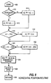
step 900 which receives the command from the main program. Step 910 tests the type of the received command to determine if it is an increment command or a decrement command. If it is an increment command,step 912 is executed which adds a value of one to an eight-bit horizontal center position variable HC. If the command is a decrement command,step 914 is executed which subtracts a value of one from the variable HC. Thesteps step 916. - The
step 916 determines if the value held by the variable HC is less than the quantity ZR/2. If it is, then the left side of the magnified image may include portions of the horizontal blanking interval. To prevent this, step 918 is executed which assigns the value ZR/2 to the variable HC. The next step executed, 920, determines if the value held in the variable HC is greater than 256- ZR/2. If so, the right side of the image may include portions of the horizontal blanking interval. To prevent this, thestep 922 is executed which assigns the value 256 - ZR/2 to the variable HC. - The next step, 924, multiplies the value held in HC by 64 and stores the result in a variable HC1. This operation converts the eight-bit HC value into an equivalent 14-bit value. Step 924 also generates a horizontal starting position value from the value HC1 and stores the generated value in a variable HPOS. The algorithm for this conversion is given in the equation (4) set forth above. At
step 926, the value HPOS is applied by themicroprocessor 712 to thelatch 716. The final step, 928, of the routine returns control to the program which invoked the horizontal position routine. - The vertical position routine is the same as the horizontal position routine shown in FIGURE 9 except that the variables VC, VC1 and VPOS replace the variables HC, HC1 and HPOS, the
step 924 multiplies VC by 16 instead of 64, and equation (5) is used instead of equation (4) to convert the value held in VC1 to a value to be stored in VPOS. - FIGURE 10 is a flow-chart diagram of a zoom routine suitable for use in this embodiment of the invention. The zoom routine starts at
step 1000 which accepts the command from the interface 710.Step 1010 determines if the command requests that the signal ZR be incremented (to reduce the magnification factor) or be decremented (to increase the magnification factor). If ZR is to be incremented,step 1012 is executed, otherwise step 1014 is executed. The next step in the routine, 1016 determines if the value held in the variable ZR is less than 51. This value corresponds to a magnification factor of five-to-one, an arbitrarily established maximum for this embodiment of the invention. If ZR is less than 51, astep 1018 sets ZR to 51.Step 1020 determines if the incremented value held in the variable ZR is greater than 256. This value corresponds to the minimum magnification factor, one-to-one.Step 1022 limits the value held in ZR to 256. After the value held in ZR has been updated, the horizontal position routine is invoked atstep 1024 and the vertical position routine is invoked atstep 1026 to recalculate the current values of HC and VC using the new value of ZR. These recalculated values for HC and VC ensure that image blanking intervals are not displayed as part of the magnified image.Step 1028 writes the calculated values of ZR, HPOS and VPOS into theregisters - While this invention has been described in terms of three exemplary embodiments, it is contemplated that it may be practiced as outlined above with modifications within the spirit and scope of the appended claims.
Claims (7)
Applications Claiming Priority (2)
| Application Number | Priority Date | Filing Date | Title |
|---|---|---|---|
| US07/340,931 US4991022A (en) | 1989-04-20 | 1989-04-20 | Apparatus and a method for automatically centering a video zoom and pan display |
| US340931 | 1989-04-20 |
Publications (3)
| Publication Number | Publication Date |
|---|---|
| EP0393663A2 true EP0393663A2 (en) | 1990-10-24 |
| EP0393663A3 EP0393663A3 (en) | 1991-02-06 |
| EP0393663B1 EP0393663B1 (en) | 1994-06-15 |
Family
ID=23335537
Family Applications (1)
| Application Number | Title | Priority Date | Filing Date |
|---|---|---|---|
| EP90107427A Expired - Lifetime EP0393663B1 (en) | 1989-04-20 | 1990-04-19 | Apparatus and a method for automatically centering a video zoom and pan display |
Country Status (12)
| Country | Link |
|---|---|
| US (1) | US4991022A (en) |
| EP (1) | EP0393663B1 (en) |
| JP (1) | JP2557720B2 (en) |
| KR (1) | KR0172942B1 (en) |
| CN (1) | CN1024245C (en) |
| AT (1) | ATE107454T1 (en) |
| CA (1) | CA2013343A1 (en) |
| DE (1) | DE69009838T2 (en) |
| DK (1) | DK0393663T3 (en) |
| ES (1) | ES2057244T3 (en) |
| FI (1) | FI97664C (en) |
| MY (1) | MY106058A (en) |
Cited By (1)
| Publication number | Priority date | Publication date | Assignee | Title |
|---|---|---|---|---|
| US7023576B1 (en) | 2000-05-09 | 2006-04-04 | Phase One A/S | Method and an apparatus for elimination of color Moiré |
Families Citing this family (32)
| Publication number | Priority date | Publication date | Assignee | Title |
|---|---|---|---|---|
| DE69028345T2 (en) * | 1989-04-18 | 1997-01-23 | Canon Kk | Image processing device |
| JPH0410783A (en) * | 1990-04-27 | 1992-01-14 | Hitachi Ltd | Video camera device |
| US5233333A (en) * | 1990-05-21 | 1993-08-03 | Borsuk Sherwin M | Portable hand held reading unit with reading aid feature |
| US5276785A (en) * | 1990-08-02 | 1994-01-04 | Xerox Corporation | Moving viewpoint with respect to a target in a three-dimensional workspace |
| JP2889686B2 (en) * | 1990-10-31 | 1999-05-10 | 三洋電機株式会社 | Integrated circuits for digital cameras |
| US5459495A (en) * | 1992-05-14 | 1995-10-17 | In Focus Systems, Inc. | Gray level addressing for LCDs |
| US5485173A (en) * | 1991-04-01 | 1996-01-16 | In Focus Systems, Inc. | LCD addressing system and method |
| US5363119A (en) * | 1991-05-01 | 1994-11-08 | Atari Games Corporation | Scaling processor for raster images |
| US5384909A (en) * | 1991-12-19 | 1995-01-24 | International Business Machines Corporation | Precision automatic scrolling for an image display system |
| US5243433A (en) * | 1992-01-06 | 1993-09-07 | Eastman Kodak Company | Digital image interpolation system for zoom and pan effects |
| KR950005944B1 (en) * | 1992-01-31 | 1995-06-07 | 주식회사금성사 | Video screen zoom apparatus |
| US5861869A (en) * | 1992-05-14 | 1999-01-19 | In Focus Systems, Inc. | Gray level addressing for LCDs |
| US5481304A (en) * | 1992-09-25 | 1996-01-02 | Samsung Electronics Co., Ltd. | Apparatus for zooming a digital video signal of a predetermined color order which is derived from a charge-coupled device |
| US5587739A (en) * | 1993-03-26 | 1996-12-24 | Nikon Corporation | Variable magnification image taking device |
| TW269091B (en) * | 1993-12-22 | 1996-01-21 | Matsushita Electric Ind Co Ltd | |
| US5774110A (en) * | 1994-01-04 | 1998-06-30 | Edelson; Steven D. | Filter RAMDAC with hardware 11/2-D zoom function |
| US5428390A (en) * | 1994-01-21 | 1995-06-27 | Texas Instruments Incorporated | Apparatus and method for focal plane zoom and pan |
| US5574572A (en) * | 1994-09-07 | 1996-11-12 | Harris Corporation | Video scaling method and device |
| KR100190841B1 (en) * | 1996-07-08 | 1999-06-01 | 윤종용 | Apparatus and method with control function of monitor display by data transmission |
| KR100283574B1 (en) * | 1996-08-27 | 2001-03-02 | 윤종용 | Monitor screen size control circuit and its control method |
| GB2317291A (en) * | 1996-09-12 | 1998-03-18 | Sharp Kk | Observer tracking directional display |
| CN1120617C (en) * | 1998-12-24 | 2003-09-03 | Tcl王牌电子(深圳)有限公司 | Interative amplification method of TV picture |
| US6323878B1 (en) * | 1999-03-03 | 2001-11-27 | Sony Corporation | System and method for providing zooming video capture |
| KR100464415B1 (en) * | 2002-05-07 | 2005-01-03 | 삼성전자주식회사 | Active video area detection circuit for display device, Method thereof and Coordinates mapping method using detected active video area |
| JP2004070654A (en) * | 2002-08-06 | 2004-03-04 | Matsushita Electric Ind Co Ltd | Portable electronic equipment |
| US20050223340A1 (en) * | 2004-03-30 | 2005-10-06 | Mikko Repka | Method of navigating in application views, electronic device, graphical user interface and computer program product |
| KR101109582B1 (en) * | 2004-11-02 | 2012-02-06 | 삼성전자주식회사 | Apparatus and method for controlling position of image when the imame is enlarged or reduced |
| CN100338950C (en) * | 2005-06-25 | 2007-09-19 | 海信集团有限公司 | Arbitrary-zone amplifying method for TV picture |
| CN101388958B (en) * | 2007-09-14 | 2010-09-29 | 鼎亿数码科技(上海)有限公司 | High-speed positioning system for high-contrast image |
| US8073291B2 (en) * | 2007-10-17 | 2011-12-06 | Seiko Epson Corporation | Center based image resizer |
| JP5438333B2 (en) * | 2009-02-05 | 2014-03-12 | キヤノン株式会社 | Display control apparatus and display control method |
| CN104181884B (en) * | 2014-08-11 | 2017-06-27 | 厦门立林科技有限公司 | A kind of intelligent home control device and method based on panoramic view |
Citations (2)
| Publication number | Priority date | Publication date | Assignee | Title |
|---|---|---|---|---|
| US4725960A (en) * | 1984-06-30 | 1988-02-16 | Fanuc Ltd. | Method of sizing an image on a graphic display for a numerical controller |
| US4774581A (en) * | 1987-04-14 | 1988-09-27 | Rca Licensing Corporation | Television picture zoom system |
Family Cites Families (12)
| Publication number | Priority date | Publication date | Assignee | Title |
|---|---|---|---|---|
| US3976982A (en) * | 1975-05-12 | 1976-08-24 | International Business Machines Corporation | Apparatus for image manipulation |
| JPS5676683A (en) * | 1979-11-28 | 1981-06-24 | Ricoh Co Ltd | Processing method for picture deformation |
| JPS5793788A (en) * | 1980-12-03 | 1982-06-10 | Nippon Hoso Kyokai <Nhk> | Chroma-key device |
| US4546349A (en) * | 1981-09-29 | 1985-10-08 | Sperry Corporation | Local zoom for raster scan displays |
| JPS58204668A (en) * | 1982-05-24 | 1983-11-29 | Dainippon Screen Mfg Co Ltd | Method for scanning and recording picture |
| DE3233288A1 (en) * | 1982-09-08 | 1984-03-08 | Robert Bosch Gmbh, 7000 Stuttgart | SYSTEM FOR TIME COMPRESSION AND / OR EXPANSION OF ELECTRICAL SIGNALS |
| US4528585A (en) * | 1983-03-30 | 1985-07-09 | Rca Corporation | Television receiver having picture magnifying apparatus |
| US4602346A (en) * | 1983-05-19 | 1986-07-22 | Matsushita Electric Industrial Co., Ltd. | Method and apparatus for processing image data using sum and subtract operations |
| US4633503A (en) * | 1984-03-19 | 1986-12-30 | The United States Of America As Represented By The Secretary Of The Navy | Video zoom processor |
| US4661987A (en) * | 1985-06-03 | 1987-04-28 | The United States Of America As Represented By The Secretary Of The Navy | Video processor |
| US4746981A (en) * | 1986-06-16 | 1988-05-24 | Imtech International, Inc. | Multiple screen digital video display |
| US4792856A (en) * | 1987-04-14 | 1988-12-20 | Rca Licensing Corporation | Sampled data memory system as for a television picture magnification system |
-
1989
- 1989-04-20 US US07/340,931 patent/US4991022A/en not_active Expired - Lifetime
- 1989-11-27 MY MYPI89001643A patent/MY106058A/en unknown
-
1990
- 1990-03-29 CA CA002013343A patent/CA2013343A1/en not_active Abandoned
- 1990-04-12 FI FI901863A patent/FI97664C/en not_active IP Right Cessation
- 1990-04-17 KR KR1019900005316A patent/KR0172942B1/en not_active IP Right Cessation
- 1990-04-19 CN CN90102681A patent/CN1024245C/en not_active Expired - Lifetime
- 1990-04-19 DE DE69009838T patent/DE69009838T2/en not_active Expired - Lifetime
- 1990-04-19 JP JP2101892A patent/JP2557720B2/en not_active Expired - Lifetime
- 1990-04-19 AT AT90107427T patent/ATE107454T1/en not_active IP Right Cessation
- 1990-04-19 ES ES90107427T patent/ES2057244T3/en not_active Expired - Lifetime
- 1990-04-19 DK DK90107427.8T patent/DK0393663T3/en active
- 1990-04-19 EP EP90107427A patent/EP0393663B1/en not_active Expired - Lifetime
Patent Citations (2)
| Publication number | Priority date | Publication date | Assignee | Title |
|---|---|---|---|---|
| US4725960A (en) * | 1984-06-30 | 1988-02-16 | Fanuc Ltd. | Method of sizing an image on a graphic display for a numerical controller |
| US4774581A (en) * | 1987-04-14 | 1988-09-27 | Rca Licensing Corporation | Television picture zoom system |
Cited By (1)
| Publication number | Priority date | Publication date | Assignee | Title |
|---|---|---|---|---|
| US7023576B1 (en) | 2000-05-09 | 2006-04-04 | Phase One A/S | Method and an apparatus for elimination of color Moiré |
Also Published As
| Publication number | Publication date |
|---|---|
| ES2057244T3 (en) | 1994-10-16 |
| CN1024245C (en) | 1994-04-13 |
| DK0393663T3 (en) | 1994-10-24 |
| DE69009838T2 (en) | 1995-01-19 |
| EP0393663B1 (en) | 1994-06-15 |
| MY106058A (en) | 1995-03-31 |
| KR0172942B1 (en) | 1999-03-20 |
| EP0393663A3 (en) | 1991-02-06 |
| JPH02296295A (en) | 1990-12-06 |
| CA2013343A1 (en) | 1990-10-20 |
| ATE107454T1 (en) | 1994-07-15 |
| US4991022A (en) | 1991-02-05 |
| DE69009838D1 (en) | 1994-07-21 |
| KR900017401A (en) | 1990-11-16 |
| FI901863A0 (en) | 1990-04-12 |
| JP2557720B2 (en) | 1996-11-27 |
| FI97664C (en) | 1997-01-27 |
| FI97664B (en) | 1996-10-15 |
| CN1046650A (en) | 1990-10-31 |
Similar Documents
| Publication | Publication Date | Title |
|---|---|---|
| EP0393663B1 (en) | Apparatus and a method for automatically centering a video zoom and pan display | |
| EP1067507B1 (en) | Image display | |
| US4988984A (en) | Image interpolator for an image display system | |
| US5452018A (en) | Digital color correction system having gross and fine adjustment modes | |
| US6778216B1 (en) | Method and apparatus for digital camera real-time image correction in preview mode | |
| CN1713268B (en) | Image interpolation apparatus | |
| US20020145610A1 (en) | Video processing engine overlay filter scaler | |
| JP2007143173A (en) | Method and apparatus for preventing keystone distortion | |
| US5253064A (en) | Video camera apparatus with electronic zoom control and method therefor | |
| GB2102603A (en) | Controlled ram signal processor | |
| EP0629044B1 (en) | Digital signal processing | |
| JP2002538738A (en) | A method for selective color control of digital video images. | |
| EP0560533A2 (en) | Localized image compression calculating method and apparatus to control anti-aliasing filtering in 3-D manipulation of 2-D video images | |
| US6741759B2 (en) | Method and apparatus for interpolation | |
| AU3329000A (en) | Image quality correcting circuit | |
| CA2119087C (en) | Gamma correcting processing of video signals | |
| JPH05173523A (en) | Multiscreen display | |
| JP2001086527A (en) | Device and method for adjusting convergence using spline interpolation | |
| EP0814429A2 (en) | An image processing system | |
| JP3047681B2 (en) | Image distortion correction method and apparatus | |
| JP3484763B2 (en) | Video data transfer device and computer system | |
| JP2004129212A (en) | Image projection device and image transformation method | |
| KR20010015738A (en) | Color signal matrix adjustment | |
| JPS6052430B2 (en) | Achromatic color control device in digital color tone control | |
| JPH0418874A (en) | Vertical thinning circuit |
Legal Events
| Date | Code | Title | Description |
|---|---|---|---|
| PUAI | Public reference made under article 153(3) epc to a published international application that has entered the european phase |
Free format text: ORIGINAL CODE: 0009012 |
|
| AK | Designated contracting states |
Kind code of ref document: A2 Designated state(s): AT DE DK ES FR GB IT |
|
| PUAL | Search report despatched |
Free format text: ORIGINAL CODE: 0009013 |
|
| AK | Designated contracting states |
Kind code of ref document: A3 Designated state(s): AT DE DK ES FR GB IT |
|
| 17P | Request for examination filed |
Effective date: 19901221 |
|
| 17Q | First examination report despatched |
Effective date: 19921228 |
|
| RAP1 | Party data changed (applicant data changed or rights of an application transferred) |
Owner name: RCA THOMSON LICENSING CORPORATION |
|
| GRAA | (expected) grant |
Free format text: ORIGINAL CODE: 0009210 |
|
| AK | Designated contracting states |
Kind code of ref document: B1 Designated state(s): AT DE DK ES FR GB IT |
|
| REF | Corresponds to: |
Ref document number: 107454 Country of ref document: AT Date of ref document: 19940715 Kind code of ref document: T |
|
| ITF | It: translation for a ep patent filed |
Owner name: ING. C. GREGORJ S.P.A. |
|
| REF | Corresponds to: |
Ref document number: 69009838 Country of ref document: DE Date of ref document: 19940721 |
|
| ET | Fr: translation filed | ||
| REG | Reference to a national code |
Ref country code: ES Ref legal event code: FG2A Ref document number: 2057244 Country of ref document: ES Kind code of ref document: T3 |
|
| REG | Reference to a national code |
Ref country code: DK Ref legal event code: T3 |
|
| PLBE | No opposition filed within time limit |
Free format text: ORIGINAL CODE: 0009261 |
|
| STAA | Information on the status of an ep patent application or granted ep patent |
Free format text: STATUS: NO OPPOSITION FILED WITHIN TIME LIMIT |
|
| 26N | No opposition filed | ||
| PGFP | Annual fee paid to national office [announced via postgrant information from national office to epo] |
Ref country code: DK Payment date: 19980303 Year of fee payment: 9 |
|
| PGFP | Annual fee paid to national office [announced via postgrant information from national office to epo] |
Ref country code: AT Payment date: 19980305 Year of fee payment: 9 |
|
| PG25 | Lapsed in a contracting state [announced via postgrant information from national office to epo] |
Ref country code: AT Free format text: LAPSE BECAUSE OF NON-PAYMENT OF DUE FEES Effective date: 19990419 |
|
| PG25 | Lapsed in a contracting state [announced via postgrant information from national office to epo] |
Ref country code: DK Free format text: LAPSE BECAUSE OF NON-PAYMENT OF DUE FEES Effective date: 19990430 |
|
| REG | Reference to a national code |
Ref country code: DK Ref legal event code: EBP |
|
| REG | Reference to a national code |
Ref country code: GB Ref legal event code: 732E |
|
| REG | Reference to a national code |
Ref country code: GB Ref legal event code: IF02 |
|
| REG | Reference to a national code |
Ref country code: FR Ref legal event code: D6 |
|
| REG | Reference to a national code |
Ref country code: GB Ref legal event code: 746 Effective date: 20030228 |
|
| PGFP | Annual fee paid to national office [announced via postgrant information from national office to epo] |
Ref country code: GB Payment date: 20090330 Year of fee payment: 20 |
|
| PGFP | Annual fee paid to national office [announced via postgrant information from national office to epo] |
Ref country code: ES Payment date: 20090508 Year of fee payment: 20 |
|
| PGFP | Annual fee paid to national office [announced via postgrant information from national office to epo] |
Ref country code: DE Payment date: 20090423 Year of fee payment: 20 Ref country code: FR Payment date: 20090423 Year of fee payment: 20 Ref country code: IT Payment date: 20090422 Year of fee payment: 20 |
|
| REG | Reference to a national code |
Ref country code: GB Ref legal event code: PE20 Expiry date: 20100418 |
|
| REG | Reference to a national code |
Ref country code: ES Ref legal event code: FD2A Effective date: 20100420 |
|
| PG25 | Lapsed in a contracting state [announced via postgrant information from national office to epo] |
Ref country code: ES Free format text: LAPSE BECAUSE OF EXPIRATION OF PROTECTION Effective date: 20100420 |
|
| PG25 | Lapsed in a contracting state [announced via postgrant information from national office to epo] |
Ref country code: GB Free format text: LAPSE BECAUSE OF EXPIRATION OF PROTECTION Effective date: 20100418 |
|
| PG25 | Lapsed in a contracting state [announced via postgrant information from national office to epo] |
Ref country code: DE Free format text: LAPSE BECAUSE OF EXPIRATION OF PROTECTION Effective date: 20100419 |