EP0394048A2 - Cartridge with liquid shield - Google Patents
Cartridge with liquid shield Download PDFInfo
- Publication number
- EP0394048A2 EP0394048A2 EP90304227A EP90304227A EP0394048A2 EP 0394048 A2 EP0394048 A2 EP 0394048A2 EP 90304227 A EP90304227 A EP 90304227A EP 90304227 A EP90304227 A EP 90304227A EP 0394048 A2 EP0394048 A2 EP 0394048A2
- Authority
- EP
- European Patent Office
- Prior art keywords
- liquid
- monitor
- shield
- cartridge
- resilient member
- Prior art date
- Legal status (The legal status is an assumption and is not a legal conclusion. Google has not performed a legal analysis and makes no representation as to the accuracy of the status listed.)
- Granted
Links
Images

Classifications
-
- B—PERFORMING OPERATIONS; TRANSPORTING
- B01—PHYSICAL OR CHEMICAL PROCESSES OR APPARATUS IN GENERAL
- B01L—CHEMICAL OR PHYSICAL LABORATORY APPARATUS FOR GENERAL USE
- B01L3/00—Containers or dishes for laboratory use, e.g. laboratory glassware; Droppers
- B01L3/50—Containers for the purpose of retaining a material to be analysed, e.g. test tubes
- B01L3/502—Containers for the purpose of retaining a material to be analysed, e.g. test tubes with fluid transport, e.g. in multi-compartment structures
- B01L3/5027—Containers for the purpose of retaining a material to be analysed, e.g. test tubes with fluid transport, e.g. in multi-compartment structures by integrated microfluidic structures, i.e. dimensions of channels and chambers are such that surface tension forces are important, e.g. lab-on-a-chip
-
- B—PERFORMING OPERATIONS; TRANSPORTING
- B01—PHYSICAL OR CHEMICAL PROCESSES OR APPARATUS IN GENERAL
- B01L—CHEMICAL OR PHYSICAL LABORATORY APPARATUS FOR GENERAL USE
- B01L2200/00—Solutions for specific problems relating to chemical or physical laboratory apparatus
- B01L2200/02—Adapting objects or devices to another
- B01L2200/026—Fluid interfacing between devices or objects, e.g. connectors, inlet details
- B01L2200/027—Fluid interfacing between devices or objects, e.g. connectors, inlet details for microfluidic devices
-
- B—PERFORMING OPERATIONS; TRANSPORTING
- B01—PHYSICAL OR CHEMICAL PROCESSES OR APPARATUS IN GENERAL
- B01L—CHEMICAL OR PHYSICAL LABORATORY APPARATUS FOR GENERAL USE
- B01L2200/00—Solutions for specific problems relating to chemical or physical laboratory apparatus
- B01L2200/08—Ergonomic or safety aspects of handling devices
- B01L2200/082—Handling hazardous material
-
- B—PERFORMING OPERATIONS; TRANSPORTING
- B01—PHYSICAL OR CHEMICAL PROCESSES OR APPARATUS IN GENERAL
- B01L—CHEMICAL OR PHYSICAL LABORATORY APPARATUS FOR GENERAL USE
- B01L2200/00—Solutions for specific problems relating to chemical or physical laboratory apparatus
- B01L2200/14—Process control and prevention of errors
- B01L2200/141—Preventing contamination, tampering
-
- B—PERFORMING OPERATIONS; TRANSPORTING
- B01—PHYSICAL OR CHEMICAL PROCESSES OR APPARATUS IN GENERAL
- B01L—CHEMICAL OR PHYSICAL LABORATORY APPARATUS FOR GENERAL USE
- B01L2300/00—Additional constructional details
- B01L2300/08—Geometry, shape and general structure
- B01L2300/0809—Geometry, shape and general structure rectangular shaped
- B01L2300/0816—Cards, e.g. flat sample carriers usually with flow in two horizontal directions
-
- B—PERFORMING OPERATIONS; TRANSPORTING
- B01—PHYSICAL OR CHEMICAL PROCESSES OR APPARATUS IN GENERAL
- B01L—CHEMICAL OR PHYSICAL LABORATORY APPARATUS FOR GENERAL USE
- B01L2400/00—Moving or stopping fluids
- B01L2400/04—Moving fluids with specific forces or mechanical means
- B01L2400/0403—Moving fluids with specific forces or mechanical means specific forces
- B01L2400/0406—Moving fluids with specific forces or mechanical means specific forces capillary forces
-
- G—PHYSICS
- G01—MEASURING; TESTING
- G01N—INVESTIGATING OR ANALYSING MATERIALS BY DETERMINING THEIR CHEMICAL OR PHYSICAL PROPERTIES
- G01N35/00—Automatic analysis not limited to methods or materials provided for in any single one of groups G01N1/00 - G01N33/00; Handling materials therefor
- G01N35/00029—Automatic analysis not limited to methods or materials provided for in any single one of groups G01N1/00 - G01N33/00; Handling materials therefor provided with flat sample substrates, e.g. slides
- G01N2035/00099—Characterised by type of test elements
- G01N2035/00138—Slides
-
- G—PHYSICS
- G01—MEASURING; TESTING
- G01N—INVESTIGATING OR ANALYSING MATERIALS BY DETERMINING THEIR CHEMICAL OR PHYSICAL PROPERTIES
- G01N35/00—Automatic analysis not limited to methods or materials provided for in any single one of groups G01N1/00 - G01N33/00; Handling materials therefor
- G01N2035/00178—Special arrangements of analysers
- G01N2035/00277—Special precautions to avoid contamination (e.g. enclosures, glove- boxes, sealed sample carriers, disposal of contaminated material)
Definitions
- This invention relates to liquid diagnostic devices and more particularly to shields for such devices to confine the excess liquid to the diagnostic devices.
- U.S. Patent 4,756,884 discloses a disposable diagnostic device in the form of a cartridge which, with the use of a monitor, can be used to substantially instantly determine the prothrombin (PT) time of one's blood.
- PT prothrombin
- Such instantaneous determination of this and other tests is of great value both to patients and to physicians in that it permits prompt diagnosis of a disease state, prescription of appropriate medication and monitoring of the proper dosage of medication, such as the oral anticoagulant coumadin commonly called Warfarin.
- the assignee has also developed a diagnostic device for measuring Activated Partial Thromboplastin Time (APTT). This is the subject of co-pending U.S. Application Serial No. 341,045, filed April 20, 1989. While the present invention has broad application beyond these specific examples, these will be used throughout this application as typical applications.
- APTT Activated Partial Thromboplastin Time
- Each of these devices mentioned above is roughly the size of a conventional plastic identification or "credit" card and is a single use disposable item. Both are used with suitable monitors about the size of a small to medium-sized book and having a receiving slot therein into which the cartridge is partially inserted in preparation for the measurement. Each cartridge has a liquid receiving well which remains outside the monitor and into which the liquid to be analyzed is deposited, either directly from a pricked finger or using a capillary tube, syringe, or the like.
- One problem is the occasional, inadvertent, seepage of excess liquid from the surface of the cartridge into the interior of the monitor such that a failsafe self-diagnostic system within the monitor will prevent it from reporting test results until the monitor is cleaned.
- internal sensors present in the monitors for the cartridges described above such as light sensing transducers and other instruments, can be affected by the unintentional presence of liquid, such as blood. If, when the self-diagnostic check is being run, the readings from the sensors are outside of the expected ranges, the monitor will withhold the reporting of any test results until the readings return to the normal range.
- the present invention provides a shield for confining liquid to be analyzed to that portion of a device, such as a cartridge surface, outside the monitor.
- This shield comprises a resilient member which, in its free state, projects away from the surface of the device to a distance sufficient to assure that it covers any gap between the liquid receiving surface of the device and the monitor in order to confine excess liquid to the surface of the device and prevent it from entering the monitor.
- the shield may be provided with sufficient resiliency to permit it to lie flat with the cartridge in its packaged state, but to automatically project upward when the package is opened so that the device is ready for use.
- An attachment means is employed which does not adversely affect the operation of the monitor or accuracy of the readings.
- the present invention provides a liquid shield particularly suited for use with liquid diagnostic devices which receive liquid at one surface and are used in connection with other equipment, such as a monitor.
- a liquid diagnostic device is one for determining the prothrombin time of one's blood by first applying a drop of blood to a well in the cartridge. The blood then automatically flows into a chamber containing reagent and continues traveling through a serpentine capillary path until sufficient clotting occurs that the capillary travel stops.
- U.S. Patent 4,756,884, incorporated herein by reference discloses such a cartridge.
- Another cartridge designed for a different analysis but which is employed in a generally similar manner with a monitor of the same general configuration is disclosed in the aforementioned co-pending U.S. Patent Application Serial No. 341,045, filed April 20, 1989, incorporated herein by reference.
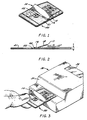
- a liquid shield device 10 according to the present invention is shown affixed to the top surface of a cartridge 20.
- the solid lines in FIG. 2 show the liquid shield 10 in its free state, that is, with no external forces applied thereto.
- the dotted lines show the liquid shield 10 deflected against the upper surface 21 of the cartridge, as when packaged, discussed below.
- the leading edge 11 of the liquid shield 10 projects upward from the otherwise substantially flat upper surface 21 of the cartridge.
- the shield is shown mounted to the cartridge substantially transverse thereto at a location between a liquid receiving well 22 and the ultimate location of the monitor surface to be shielded with the cartridge in its installed condition. This location is illustrated in FIGS. 3 and 4.
- This arrangement allows the shield 10 to accomplish the desired confining of the liquid to the cartridge surface and shielding of the monitor surface 31 from contact by the liquid.
- the shield may be attached to the cartridge at a location sufficiently far back from the monitor surface 31 to avoid interference by the shield when the leading portion of the cartridge is inserted and seated into position in the monitor.
- the upstanding "flap" 12 of the shield 10 may be positioned to engage and ride up the monitor surface 31 as the cartridge 20 is inserted into the monitor. This arrangement assures that the shield is rendered unobtrusive while the cartridge is in place in the monitor.
- An additional advantage of this arrangement, especially when the shield is made of a substantially opaque material, is that the shield can serve an auxiliary purpose of preventing the entry of light into any gap 32 between the cartridge surface 21 and the monitor surface 31 which might otherwise impair the functioning of any light-sensitive instruments or transducers (shown generally at 34) within the monitor.
- a further advantage of making the shield from an opaque material is that the orientation of the flap 12 of the liquid shield can also be passively verified by even the monitors presently in the field. The manner in which this is accomplished can be appreciated by reference to FIG. 4.
- the flap portion 12 of the liquid shield 10 should enter the gap 32, as indicated by the dotted lines 12′, it will be interposed between a light source and sensor (shown schematically at 34 and 35), and will indicate a malfunction.
- a light source and sensor shown schematically at 34 and 35
- the program may readily be supplemented to include an appropriate message to indicate that the light path has been blocked. This message could prompt the user to remove the cartridge and either reinsert it correctly or substitute another cartridge.
- the liquid shield 10 not significantly increase the effective packing thickness "t" of the cartridge.
- a sufficiently resilient material such as a thin plastic film
- Materials considered suitable for the liquid shield are films of polysulfone, polyester, cellulose acetate, polycarbonate, polyetheretherketone, polymethylpentene, polyetherimide, polyethersulfone, polyvinylidene fluoride, metal foils, reinforced papers and laminates of these materials.
- the angle ⁇ which the flap 12 makes with the surface 21 of the cartridge 20 may range between the minimum required to assure that the flap does not enter the gap 32 and the angle of inclination of the monitor surface 31. Specifically, angles of between about 10° and 45° may be suitable, with the preferred range for the cartridge and monitor shown being between about 25° and 35°.
- the thickness of the material can vary so long as the shield accomplishes the desired functions as set forth above. Depending on the specific material selected, films as thin as a couple thousandths of an inch may be satisfactory. A 0.004" thick polysulfone film, heat-formed to have an angle ⁇ of approximately 25° between the portion 14 of the shield fastened to the cartridge and upstanding flap 12, has been found to work highly satisfactorily.
- the manner in which the portion 14 of the liquid shield 10 is attached to the surface 21 of the cartridge 20 is important from several standpoints.
- the shield must remain firmly attached throughout its shelf life, during most of which time it may be sealed within a foil or similar pouch.
- the shield itself, and any adhesive material (shown in the drawings as item 40) which is used to attach the shield to the cartridge, must not adversely affect the operation of the cartridge. Specifically in this regard, any such adhesive must not release such quantities of vapors incompatible with the remainder of the cartridges, or the reagents coated on the internal surfaces thereof, as might ultimately impair the functioning or accuracy of the results obtained using the cartridge.
- An adhesive which has been found to be suitable in attaching a polysulfone liquid shield to a cartridge molded from acrylonitrile-butadiene-styrene (ABS) resin is 3M 966.
- Other acrylic and rubber based adhesives have been shown to be suitable. Ultrasonic welding and heat sealing may also be suitable alternatives which avoid the use of separate adhesives entirely.
- liquid may be added to the well 22 of the cartridge 20 directly from a pricked finger, or using any other conventional means, such as a capillary tube or syringe (depicted in FIG. 4 as item 60). Under normal circumstances a single drop or two of the liquid is sufficient for the analysis and will be readily contained in the well. Under these conditions, the liquid shield 10 will be unnecessary to block liquid although, as discussed above, it may still fulfill a useful light-blocking function. In the event excess liquid is introduced onto the surface of the cartridge, as indicated at 50 in FIGS.
Abstract
Description
- This invention relates to liquid diagnostic devices and more particularly to shields for such devices to confine the excess liquid to the diagnostic devices.
- U.S. Patent 4,756,884 discloses a disposable diagnostic device in the form of a cartridge which, with the use of a monitor, can be used to substantially instantly determine the prothrombin (PT) time of one's blood. Such instantaneous determination of this and other tests is of great value both to patients and to physicians in that it permits prompt diagnosis of a disease state, prescription of appropriate medication and monitoring of the proper dosage of medication, such as the oral anticoagulant coumadin commonly called Warfarin. The assignee has also developed a diagnostic device for measuring Activated Partial Thromboplastin Time (APTT). This is the subject of co-pending U.S. Application Serial No. 341,045, filed April 20, 1989. While the present invention has broad application beyond these specific examples, these will be used throughout this application as typical applications.
- Each of these devices mentioned above is roughly the size of a conventional plastic identification or "credit" card and is a single use disposable item. Both are used with suitable monitors about the size of a small to medium-sized book and having a receiving slot therein into which the cartridge is partially inserted in preparation for the measurement. Each cartridge has a liquid receiving well which remains outside the monitor and into which the liquid to be analyzed is deposited, either directly from a pricked finger or using a capillary tube, syringe, or the like.
- Two related problems and disadvantages have been recognized, and the present invention has been developed to solve both of them. One problem is the occasional, inadvertent, seepage of excess liquid from the surface of the cartridge into the interior of the monitor such that a failsafe self-diagnostic system within the monitor will prevent it from reporting test results until the monitor is cleaned. Specifically, internal sensors present in the monitors for the cartridges described above, such as light sensing transducers and other instruments, can be affected by the unintentional presence of liquid, such as blood. If, when the self-diagnostic check is being run, the readings from the sensors are outside of the expected ranges, the monitor will withhold the reporting of any test results until the readings return to the normal range.
- A related problem, apart from having liquid interfere with the operation of the monitor, is the contamination of the monitor which results from contact of the liquid with either the interior or exterior of the monitor. Not only is such contact unsightly and unsanitary, but the hazards of contact with infected bodily liquids of the diagnosee, and the desirability of preventing such contact, are so apparent as to require no further elaboration. Whether the contact of the excess liquid renders the monitor completely inoperative or simply contaminates the monitor, it requires removal of the monitor from service so that it can be cleaned and repaired if necessary.
- The problem of confining excess liquid to the surface of cartridges such as those disclosed in the referenced patents is complicated by a series of factors. One such factor is the desirability that the device be ready to use immediately upon its removal from its packaging. Another factor is the need for space efficient nesting of the packaged cartridges to reduce storage space requirements. Yet another consideration is that the liquid shield not change or otherwise adversely affect the design or manufacture of the cartridges, which involves some ultrasonic assembly steps requiring flat cartridge surfaces. Still another consideration is the requirement that neither the liquid shield, nor any material used to attach it, impair or interfere with the accuracy of results obtained when using the cartridge with an appropriate monitor. Further, it is desirable that new shielded cartridges be usable with monitors already in the field.
- The present invention provides a shield for confining liquid to be analyzed to that portion of a device, such as a cartridge surface, outside the monitor. This shield comprises a resilient member which, in its free state, projects away from the surface of the device to a distance sufficient to assure that it covers any gap between the liquid receiving surface of the device and the monitor in order to confine excess liquid to the surface of the device and prevent it from entering the monitor. The shield may be provided with sufficient resiliency to permit it to lie flat with the cartridge in its packaged state, but to automatically project upward when the package is opened so that the device is ready for use. An attachment means is employed which does not adversely affect the operation of the monitor or accuracy of the readings.
- This invention will be better understood by reference to the following detailed description of specific embodiments when considered in combination with the drawings that form part of this specification, wherein:
- FIGURE 1 is a perspective view of a liquid diagnostic cartridge with a liquid shield according to the present invention applied thereto;
- FIG. 2 is a side view of the cartridge and liquid shield of FIG. 1;
- FIG. 3 is a perspective view of the cartridge and liquid shield of FIG. 1 being inserted into a monitor; and
- FIG. 4 is a perspective view of the cartridge and liquid shield of FIG. 1 fully inserted into the monitor and receiving an excess amount of liquid from a syringe.
- FIG. 5 is a partial sectional view of the cartridge, liquid shield and monitor of FIG. 4 taken along line 5-5.
- The present invention provides a liquid shield particularly suited for use with liquid diagnostic devices which receive liquid at one surface and are used in connection with other equipment, such as a monitor. One example of such a liquid diagnostic device is one for determining the prothrombin time of one's blood by first applying a drop of blood to a well in the cartridge. The blood then automatically flows into a chamber containing reagent and continues traveling through a serpentine capillary path until sufficient clotting occurs that the capillary travel stops. U.S. Patent 4,756,884, incorporated herein by reference, discloses such a cartridge. Another cartridge designed for a different analysis but which is employed in a generally similar manner with a monitor of the same general configuration is disclosed in the aforementioned co-pending U.S. Patent Application Serial No. 341,045, filed April 20, 1989, incorporated herein by reference.
- Referring jointly to FIGS. 1 and 2, a
liquid shield device 10 according to the present invention is shown affixed to the top surface of acartridge 20. The solid lines in FIG. 2 show theliquid shield 10 in its free state, that is, with no external forces applied thereto. The dotted lines show theliquid shield 10 deflected against theupper surface 21 of the cartridge, as when packaged, discussed below. - In the free state shown in FIGS. 1 and 2, the leading edge 11 of the
liquid shield 10 projects upward from the otherwise substantially flatupper surface 21 of the cartridge. The shield is shown mounted to the cartridge substantially transverse thereto at a location between a liquid receiving well 22 and the ultimate location of the monitor surface to be shielded with the cartridge in its installed condition. This location is illustrated in FIGS. 3 and 4. This arrangement allows theshield 10 to accomplish the desired confining of the liquid to the cartridge surface and shielding of the monitor surface 31 from contact by the liquid. By fabricating the shield from a resilient material, such as a thin plastic or metallic film, the shield may be attached to the cartridge at a location sufficiently far back from the monitor surface 31 to avoid interference by the shield when the leading portion of the cartridge is inserted and seated into position in the monitor. In this regard it will be appreciated that the upstanding "flap" 12 of theshield 10 may be positioned to engage and ride up the monitor surface 31 as thecartridge 20 is inserted into the monitor. This arrangement assures that the shield is rendered unobtrusive while the cartridge is in place in the monitor. An additional advantage of this arrangement, especially when the shield is made of a substantially opaque material, is that the shield can serve an auxiliary purpose of preventing the entry of light into any gap 32 between thecartridge surface 21 and the monitor surface 31 which might otherwise impair the functioning of any light-sensitive instruments or transducers (shown generally at 34) within the monitor. A further advantage of making the shield from an opaque material is that the orientation of theflap 12 of the liquid shield can also be passively verified by even the monitors presently in the field. The manner in which this is accomplished can be appreciated by reference to FIG. 4. - In the event the
flap portion 12 of theliquid shield 10 should enter the gap 32, as indicated by thedotted lines 12′, it will be interposed between a light source and sensor (shown schematically at 34 and 35), and will indicate a malfunction. Inasmuch as the monitors in the field already employ a self-diagnostic program which displays alpha/numeric messages atreadout 36 the program may readily be supplemented to include an appropriate message to indicate that the light path has been blocked. This message could prompt the user to remove the cartridge and either reinsert it correctly or substitute another cartridge. - It will be appreciated that, in the interest of efficient packing and storage, it is highly desirable that the
liquid shield 10 not significantly increase the effective packing thickness "t" of the cartridge. To this end, by making the liquid shield of a sufficiently resilient material, such as a thin plastic film, it may be readily flattened against the cartridge as shown in FIG. 2A. Materials considered suitable for the liquid shield are films of polysulfone, polyester, cellulose acetate, polycarbonate, polyetheretherketone, polymethylpentene, polyetherimide, polyethersulfone, polyvinylidene fluoride, metal foils, reinforced papers and laminates of these materials. - The angle α which the
flap 12 makes with thesurface 21 of thecartridge 20 may range between the minimum required to assure that the flap does not enter the gap 32 and the angle of inclination of the monitor surface 31. Specifically, angles of between about 10° and 45° may be suitable, with the preferred range for the cartridge and monitor shown being between about 25° and 35°. - The thickness of the material can vary so long as the shield accomplishes the desired functions as set forth above. Depending on the specific material selected, films as thin as a couple thousandths of an inch may be satisfactory. A 0.004" thick polysulfone film, heat-formed to have an angle α of approximately 25° between the
portion 14 of the shield fastened to the cartridge andupstanding flap 12, has been found to work highly satisfactorily. - The manner in which the
portion 14 of theliquid shield 10 is attached to thesurface 21 of thecartridge 20 is important from several standpoints. First, the shield must remain firmly attached throughout its shelf life, during most of which time it may be sealed within a foil or similar pouch. Secondly, the shield itself, and any adhesive material (shown in the drawings as item 40) which is used to attach the shield to the cartridge, must not adversely affect the operation of the cartridge. Specifically in this regard, any such adhesive must not release such quantities of vapors incompatible with the remainder of the cartridges, or the reagents coated on the internal surfaces thereof, as might ultimately impair the functioning or accuracy of the results obtained using the cartridge. An adhesive which has been found to be suitable in attaching a polysulfone liquid shield to a cartridge molded from acrylonitrile-butadiene-styrene (ABS) resin is 3M 966. Other acrylic and rubber based adhesives have been shown to be suitable. Ultrasonic welding and heat sealing may also be suitable alternatives which avoid the use of separate adhesives entirely. - The operation of the liquid shield is considered to be apparent from the foregoing discussion. Briefly explaining it with specific reference to FIGS. 4 and 5, however, liquid may be added to the well 22 of the
cartridge 20 directly from a pricked finger, or using any other conventional means, such as a capillary tube or syringe (depicted in FIG. 4 as item 60). Under normal circumstances a single drop or two of the liquid is sufficient for the analysis and will be readily contained in the well. Under these conditions, theliquid shield 10 will be unnecessary to block liquid although, as discussed above, it may still fulfill a useful light-blocking function. In the event excess liquid is introduced onto the surface of the cartridge, as indicated at 50 in FIGS. 4 and 5, the possibility exists that, without the liquid shield of the present invention, the liquid might reach the surface 31 of the monitor, and/or enter the gap 32. It must be recognized that the embodiment of the liquid shield shown in the figures will not be effective against a "flood" of a great excess of liquid. It will, nevertheless, be effective in the vast majority of instances where there is a moderate excess of liquid, or where an otherwise proper amount of liquid is errantly applied. - From the above discussion, it will be appreciated that there is described a liquid shield for use with diagnostic cartridges which can be applied to cartridges of existing design without necessitating any changes to the basic cartridge manufacture, or the design or manufacture of the monitors designed for use with the cartridges.
- The invention now being fully described, it will be apparent to one of ordinary skill in the art that many changes and modifications can be made thereto without departing from the spirit or scope of the appended claims.
Claims (7)
a resilient member adapted to be attached to the surface of the device which receives the liquid, a portion of the resilient member adapted to project away from the surface of the device a distance sufficient to assure that it does not enter the interior of the monitor but instead shields any gap between the liquid receiving surface of the device and the monitor whereby excess liquid may be confined to the device and prevented from entering the monitor.
a resilient member attached to the surface of the device which receives the liquid, a portion of the resilient member projecting away from the surface of the device a distance sufficient to assure that it does not enter the interior of the monitor but instead shields any gap between the liquid receiving surface of the device and the monitor whereby excess liquid may be confined to the device and prevented from entering the monitor.
Applications Claiming Priority (2)
| Application Number | Priority Date | Filing Date | Title |
|---|---|---|---|
| US07/341,757 US4952373A (en) | 1989-04-21 | 1989-04-21 | Liquid shield for cartridge |
| US341757 | 1989-04-21 |
Publications (3)
| Publication Number | Publication Date |
|---|---|
| EP0394048A2 true EP0394048A2 (en) | 1990-10-24 |
| EP0394048A3 EP0394048A3 (en) | 1991-06-12 |
| EP0394048B1 EP0394048B1 (en) | 1994-10-05 |
Family
ID=23338907
Family Applications (1)
| Application Number | Title | Priority Date | Filing Date |
|---|---|---|---|
| EP90304227A Expired - Lifetime EP0394048B1 (en) | 1989-04-21 | 1990-04-19 | Cartridge with liquid shield |
Country Status (8)
| Country | Link |
|---|---|
| US (1) | US4952373A (en) |
| EP (1) | EP0394048B1 (en) |
| JP (1) | JP2561364B2 (en) |
| AT (1) | ATE112509T1 (en) |
| AU (1) | AU618461B2 (en) |
| CA (2) | CA1334737C (en) |
| DE (1) | DE69013043T2 (en) |
| ES (1) | ES2064623T3 (en) |
Cited By (5)
| Publication number | Priority date | Publication date | Assignee | Title |
|---|---|---|---|---|
| WO1999003584A1 (en) * | 1997-07-21 | 1999-01-28 | Ysi Incorporated | Microfluidic analyzer module |
| US6073482A (en) * | 1997-07-21 | 2000-06-13 | Ysi Incorporated | Fluid flow module |
| US6293012B1 (en) | 1997-07-21 | 2001-09-25 | Ysi Incorporated | Method of making a fluid flow module |
| WO2002013966A2 (en) * | 2000-08-11 | 2002-02-21 | Lifescan, Inc. | Strip holder for use in a test strip meter |
| WO2006034272A2 (en) * | 2004-09-20 | 2006-03-30 | Bayer Healthcare Llc | An optical sensor and methods of making it |
Families Citing this family (77)
| Publication number | Priority date | Publication date | Assignee | Title |
|---|---|---|---|---|
| AU633965B2 (en) * | 1989-09-08 | 1993-02-11 | Terumo Kabushiki Kaisha | Test instrument |
| CA2062027C (en) * | 1991-03-04 | 1998-05-19 | William Aldrich | Liquid control system for diagnostic cartridges used in analytical instruments |
| GB9126987D0 (en) * | 1991-12-19 | 1992-02-19 | Gorog Diana | Improvements in and relating to blood measurements |
| US5223219A (en) * | 1992-04-10 | 1993-06-29 | Biotrack, Inc. | Analytical cartridge and system for detecting analytes in liquid samples |
| WO1994011489A1 (en) * | 1992-11-06 | 1994-05-26 | Biolog, Inc. | Testing device for liquid and liquid suspended samples |
| BR9406010A (en) * | 1993-03-17 | 1995-12-26 | Akzo Nobel Nv | Apparatus and process for detecting at least one substance reacting specifically in a sample collection test liquid and device |
| US5597532A (en) * | 1994-10-20 | 1997-01-28 | Connolly; James | Apparatus for determining substances contained in a body fluid |
| US5728352A (en) * | 1994-11-14 | 1998-03-17 | Advanced Care Products | Disposable electronic diagnostic instrument |
| US5800778A (en) * | 1995-05-31 | 1998-09-01 | Biomerieux Vitek, Inc. | Sealant for sample holder |
| US5833924A (en) * | 1995-12-22 | 1998-11-10 | Universal Healthwatch, Inc. | Sampling-assay device and interface system |
| US5833923A (en) * | 1995-12-22 | 1998-11-10 | Universal Healthwatch, Inc. | Sampling-assay interface system |
| US5736404A (en) * | 1995-12-27 | 1998-04-07 | Zia Yassinzadeh | Flow detection appartus and method |
| US5753429A (en) * | 1996-08-09 | 1998-05-19 | Lifescan, Inc. | Analyte concentration measurement using a hollow frustum |
| US6099802A (en) * | 1996-08-09 | 2000-08-08 | Lifescan, Inc. | Hollow frustum reagent test device |
| US5846486A (en) * | 1996-08-09 | 1998-12-08 | Lifescan, Inc. | Hollow frustum reagent test device |
| US5736103A (en) | 1996-08-09 | 1998-04-07 | Lifescan, Inc. | Remote-dosing analyte concentration meter |
| US5714123A (en) * | 1996-09-30 | 1998-02-03 | Lifescan, Inc. | Protective shield for a blood glucose strip |
| US6426230B1 (en) | 1997-08-01 | 2002-07-30 | Qualigen, Inc. | Disposable diagnostic device and method |
| US5876675A (en) * | 1997-08-05 | 1999-03-02 | Caliper Technologies Corp. | Microfluidic devices and systems |
| DE19753850A1 (en) * | 1997-12-04 | 1999-06-10 | Roche Diagnostics Gmbh | Sampling device |
| DE19753847A1 (en) | 1997-12-04 | 1999-06-10 | Roche Diagnostics Gmbh | Analytical test element with capillary channel |
| US6391005B1 (en) | 1998-03-30 | 2002-05-21 | Agilent Technologies, Inc. | Apparatus and method for penetration with shaft having a sensor for sensing penetration depth |
| US20050037505A1 (en) * | 2000-05-11 | 2005-02-17 | James Samsoondar | Spectroscopic method and apparatus for analyte measurement |
| US6458326B1 (en) * | 1999-11-24 | 2002-10-01 | Home Diagnostics, Inc. | Protective test strip platform |
| US7485454B1 (en) | 2000-03-10 | 2009-02-03 | Bioprocessors Corp. | Microreactor |
| US8641644B2 (en) | 2000-11-21 | 2014-02-04 | Sanofi-Aventis Deutschland Gmbh | Blood testing apparatus having a rotatable cartridge with multiple lancing elements and testing means |
| JP2004527247A (en) * | 2001-04-10 | 2004-09-09 | バイオプロセッサーズ コーポレイション | Microfermentor devices and cell-based screening methods |
| US6759009B2 (en) | 2001-05-04 | 2004-07-06 | Portascience Incorporated | Method and device for clotting time assay |
| US9795747B2 (en) | 2010-06-02 | 2017-10-24 | Sanofi-Aventis Deutschland Gmbh | Methods and apparatus for lancet actuation |
| US7025774B2 (en) | 2001-06-12 | 2006-04-11 | Pelikan Technologies, Inc. | Tissue penetration device |
| US7981056B2 (en) | 2002-04-19 | 2011-07-19 | Pelikan Technologies, Inc. | Methods and apparatus for lancet actuation |
| DE60234598D1 (en) | 2001-06-12 | 2010-01-14 | Pelikan Technologies Inc | SELF-OPTIMIZING LANZET DEVICE WITH ADAPTANT FOR TEMPORAL FLUCTUATIONS OF SKIN PROPERTIES |
| ATE485766T1 (en) | 2001-06-12 | 2010-11-15 | Pelikan Technologies Inc | ELECTRICAL ACTUATING ELEMENT FOR A LANCET |
| US9226699B2 (en) | 2002-04-19 | 2016-01-05 | Sanofi-Aventis Deutschland Gmbh | Body fluid sampling module with a continuous compression tissue interface surface |
| US9427532B2 (en) | 2001-06-12 | 2016-08-30 | Sanofi-Aventis Deutschland Gmbh | Tissue penetration device |
| US7749174B2 (en) | 2001-06-12 | 2010-07-06 | Pelikan Technologies, Inc. | Method and apparatus for lancet launching device intergrated onto a blood-sampling cartridge |
| US8337419B2 (en) | 2002-04-19 | 2012-12-25 | Sanofi-Aventis Deutschland Gmbh | Tissue penetration device |
| US8360992B2 (en) | 2002-04-19 | 2013-01-29 | Sanofi-Aventis Deutschland Gmbh | Method and apparatus for penetrating tissue |
| US7976476B2 (en) | 2002-04-19 | 2011-07-12 | Pelikan Technologies, Inc. | Device and method for variable speed lancet |
| US8267870B2 (en) | 2002-04-19 | 2012-09-18 | Sanofi-Aventis Deutschland Gmbh | Method and apparatus for body fluid sampling with hybrid actuation |
| US7892185B2 (en) | 2002-04-19 | 2011-02-22 | Pelikan Technologies, Inc. | Method and apparatus for body fluid sampling and analyte sensing |
| US7229458B2 (en) | 2002-04-19 | 2007-06-12 | Pelikan Technologies, Inc. | Method and apparatus for penetrating tissue |
| US7226461B2 (en) | 2002-04-19 | 2007-06-05 | Pelikan Technologies, Inc. | Method and apparatus for a multi-use body fluid sampling device with sterility barrier release |
| US7901362B2 (en) | 2002-04-19 | 2011-03-08 | Pelikan Technologies, Inc. | Method and apparatus for penetrating tissue |
| US8579831B2 (en) | 2002-04-19 | 2013-11-12 | Sanofi-Aventis Deutschland Gmbh | Method and apparatus for penetrating tissue |
| US7232451B2 (en) | 2002-04-19 | 2007-06-19 | Pelikan Technologies, Inc. | Method and apparatus for penetrating tissue |
| US9314194B2 (en) | 2002-04-19 | 2016-04-19 | Sanofi-Aventis Deutschland Gmbh | Tissue penetration device |
| US7297122B2 (en) | 2002-04-19 | 2007-11-20 | Pelikan Technologies, Inc. | Method and apparatus for penetrating tissue |
| US7331931B2 (en) | 2002-04-19 | 2008-02-19 | Pelikan Technologies, Inc. | Method and apparatus for penetrating tissue |
| US7491178B2 (en) | 2002-04-19 | 2009-02-17 | Pelikan Technologies, Inc. | Method and apparatus for penetrating tissue |
| US9795334B2 (en) | 2002-04-19 | 2017-10-24 | Sanofi-Aventis Deutschland Gmbh | Method and apparatus for penetrating tissue |
| US7909778B2 (en) | 2002-04-19 | 2011-03-22 | Pelikan Technologies, Inc. | Method and apparatus for penetrating tissue |
| US9248267B2 (en) | 2002-04-19 | 2016-02-02 | Sanofi-Aventis Deustchland Gmbh | Tissue penetration device |
| US8702624B2 (en) | 2006-09-29 | 2014-04-22 | Sanofi-Aventis Deutschland Gmbh | Analyte measurement device with a single shot actuator |
| US7547287B2 (en) | 2002-04-19 | 2009-06-16 | Pelikan Technologies, Inc. | Method and apparatus for penetrating tissue |
| US7175642B2 (en) | 2002-04-19 | 2007-02-13 | Pelikan Technologies, Inc. | Methods and apparatus for lancet actuation |
| US7892183B2 (en) | 2002-04-19 | 2011-02-22 | Pelikan Technologies, Inc. | Method and apparatus for body fluid sampling and analyte sensing |
| US8784335B2 (en) | 2002-04-19 | 2014-07-22 | Sanofi-Aventis Deutschland Gmbh | Body fluid sampling device with a capacitive sensor |
| US7674232B2 (en) | 2002-04-19 | 2010-03-09 | Pelikan Technologies, Inc. | Method and apparatus for penetrating tissue |
| US8221334B2 (en) | 2002-04-19 | 2012-07-17 | Sanofi-Aventis Deutschland Gmbh | Method and apparatus for penetrating tissue |
| US8574895B2 (en) | 2002-12-30 | 2013-11-05 | Sanofi-Aventis Deutschland Gmbh | Method and apparatus using optical techniques to measure analyte levels |
| EP1628567B1 (en) | 2003-05-30 | 2010-08-04 | Pelikan Technologies Inc. | Method and apparatus for fluid injection |
| DK1633235T3 (en) | 2003-06-06 | 2014-08-18 | Sanofi Aventis Deutschland | Apparatus for sampling body fluid and detecting analyte |
| WO2006001797A1 (en) | 2004-06-14 | 2006-01-05 | Pelikan Technologies, Inc. | Low pain penetrating |
| US8282576B2 (en) | 2003-09-29 | 2012-10-09 | Sanofi-Aventis Deutschland Gmbh | Method and apparatus for an improved sample capture device |
| EP1680014A4 (en) | 2003-10-14 | 2009-01-21 | Pelikan Technologies Inc | Method and apparatus for a variable user interface |
| US7822454B1 (en) | 2005-01-03 | 2010-10-26 | Pelikan Technologies, Inc. | Fluid sampling device with improved analyte detecting member configuration |
| EP1706026B1 (en) | 2003-12-31 | 2017-03-01 | Sanofi-Aventis Deutschland GmbH | Method and apparatus for improving fluidic flow and sample capture |
| US8828203B2 (en) | 2004-05-20 | 2014-09-09 | Sanofi-Aventis Deutschland Gmbh | Printable hydrogels for biosensors |
| EP1765194A4 (en) | 2004-06-03 | 2010-09-29 | Pelikan Technologies Inc | Method and apparatus for a fluid sampling device |
| US9775553B2 (en) | 2004-06-03 | 2017-10-03 | Sanofi-Aventis Deutschland Gmbh | Method and apparatus for a fluid sampling device |
| US8652831B2 (en) | 2004-12-30 | 2014-02-18 | Sanofi-Aventis Deutschland Gmbh | Method and apparatus for analyte measurement test time |
| AU2008265610B2 (en) | 2007-06-21 | 2012-08-23 | Gen-Probe Incorporated | Instrument and receptacles for performing processes |
| WO2009126900A1 (en) | 2008-04-11 | 2009-10-15 | Pelikan Technologies, Inc. | Method and apparatus for analyte detecting device |
| US9375169B2 (en) | 2009-01-30 | 2016-06-28 | Sanofi-Aventis Deutschland Gmbh | Cam drive for managing disposable penetrating member actions with a single motor and motor and control system |
| US8965476B2 (en) | 2010-04-16 | 2015-02-24 | Sanofi-Aventis Deutschland Gmbh | Tissue penetration device |
| US10386376B2 (en) | 2015-11-09 | 2019-08-20 | Jeimei, Llc | Sample container with integrated test strip |
Citations (2)
| Publication number | Priority date | Publication date | Assignee | Title |
|---|---|---|---|---|
| EP0222466A2 (en) * | 1985-10-31 | 1987-05-20 | Bio/Data Corporation | Apparatus and method for automatically performing analytical testing of individual fluid samples |
| EP0287005A2 (en) * | 1987-04-11 | 1988-10-19 | Kabushiki Kaisha Kyoto Daiichi Kagaku | A method for chemically analyzing a sample using a test piece |
Family Cites Families (6)
| Publication number | Priority date | Publication date | Assignee | Title |
|---|---|---|---|---|
| US3127855A (en) * | 1960-08-02 | 1964-04-07 | Instr For Res & Industry | Laboratory apparatus shields |
| US3957583A (en) * | 1974-12-02 | 1976-05-18 | Mcdonnell Douglas Corporation | Apparatus and process for determining the susceptibility of microorganisms to antibiotics |
| US4018652A (en) * | 1976-01-09 | 1977-04-19 | Mcdonnell Douglas Corporation | Process and apparatus for ascertaining the concentration of microorganism in a water specimen |
| US4038151A (en) * | 1976-07-29 | 1977-07-26 | Mcdonnell Douglas Corporation | Card for use in an automated microbial detection system |
| US4318994A (en) * | 1979-08-30 | 1982-03-09 | Mcdonnell Douglas Corporation | Enterobacteriaceae species biochemical test card |
| JPH0255952A (en) * | 1988-08-15 | 1990-02-26 | Technimed Corp | Dry chemical reagent release product, manufacture thereof and analysis method and test kit using the same |
-
1989
- 1989-04-21 US US07/341,757 patent/US4952373A/en not_active Expired - Lifetime
- 1989-09-26 CA CA000613159A patent/CA1334737C/en not_active Expired - Fee Related
-
1990
- 1990-04-02 AU AU52494/90A patent/AU618461B2/en not_active Ceased
- 1990-04-03 CA CA002013695A patent/CA2013695A1/en not_active Abandoned
- 1990-04-19 ES ES90304227T patent/ES2064623T3/en not_active Expired - Lifetime
- 1990-04-19 DE DE69013043T patent/DE69013043T2/en not_active Expired - Fee Related
- 1990-04-19 EP EP90304227A patent/EP0394048B1/en not_active Expired - Lifetime
- 1990-04-19 AT AT90304227T patent/ATE112509T1/en not_active IP Right Cessation
- 1990-04-21 JP JP2106306A patent/JP2561364B2/en not_active Expired - Fee Related
Patent Citations (2)
| Publication number | Priority date | Publication date | Assignee | Title |
|---|---|---|---|---|
| EP0222466A2 (en) * | 1985-10-31 | 1987-05-20 | Bio/Data Corporation | Apparatus and method for automatically performing analytical testing of individual fluid samples |
| EP0287005A2 (en) * | 1987-04-11 | 1988-10-19 | Kabushiki Kaisha Kyoto Daiichi Kagaku | A method for chemically analyzing a sample using a test piece |
Cited By (12)
| Publication number | Priority date | Publication date | Assignee | Title |
|---|---|---|---|---|
| WO1999003584A1 (en) * | 1997-07-21 | 1999-01-28 | Ysi Incorporated | Microfluidic analyzer module |
| US5932799A (en) * | 1997-07-21 | 1999-08-03 | Ysi Incorporated | Microfluidic analyzer module |
| US6073482A (en) * | 1997-07-21 | 2000-06-13 | Ysi Incorporated | Fluid flow module |
| US6293012B1 (en) | 1997-07-21 | 2001-09-25 | Ysi Incorporated | Method of making a fluid flow module |
| EP1520621A2 (en) * | 1997-07-21 | 2005-04-06 | Ysi Incorporated | Microfluidic analyzer module |
| EP1520621A3 (en) * | 1997-07-21 | 2006-06-07 | Ysi Incorporated | Microfluidic analyzer module |
| WO2002013966A2 (en) * | 2000-08-11 | 2002-02-21 | Lifescan, Inc. | Strip holder for use in a test strip meter |
| WO2002013966A3 (en) * | 2000-08-11 | 2002-06-27 | Lifescan Inc | Strip holder for use in a test strip meter |
| US6652814B1 (en) | 2000-08-11 | 2003-11-25 | Lifescan, Inc. | Strip holder for use in a test strip meter |
| AU2001280844B2 (en) * | 2000-08-11 | 2005-11-10 | Lifescan, Inc. | Strip holder for use in a test strip meter |
| WO2006034272A2 (en) * | 2004-09-20 | 2006-03-30 | Bayer Healthcare Llc | An optical sensor and methods of making it |
| WO2006034272A3 (en) * | 2004-09-20 | 2006-05-18 | Bayer Healthcare Llc | An optical sensor and methods of making it |
Also Published As
| Publication number | Publication date |
|---|---|
| EP0394048A3 (en) | 1991-06-12 |
| ATE112509T1 (en) | 1994-10-15 |
| CA1334737C (en) | 1995-03-14 |
| US4952373A (en) | 1990-08-28 |
| JPH0341361A (en) | 1991-02-21 |
| DE69013043T2 (en) | 1995-05-04 |
| CA2013695A1 (en) | 1990-10-21 |
| ES2064623T3 (en) | 1995-02-01 |
| EP0394048B1 (en) | 1994-10-05 |
| AU5249490A (en) | 1990-11-22 |
| DE69013043D1 (en) | 1994-11-10 |
| JP2561364B2 (en) | 1996-12-04 |
| AU618461B2 (en) | 1991-12-19 |
Similar Documents
| Publication | Publication Date | Title |
|---|---|---|
| EP0394048B1 (en) | Cartridge with liquid shield | |
| US5714123A (en) | Protective shield for a blood glucose strip | |
| EP0502691B1 (en) | Liquid control system for diagnostic cartridges used in analytical instruments | |
| AU773191B2 (en) | Urine collection cup | |
| EP0512059B1 (en) | Disposable diagnostic system | |
| EP2387941B1 (en) | Integrated test strip container with retaining insert | |
| US7294502B2 (en) | Device for collecting liquid samples | |
| CA2511175C (en) | Body fluid testing device | |
| AU2011307356B2 (en) | Improved electronic analyte assaying device | |
| EP0901634B1 (en) | A system for determining at least one parameter of at least one sample of a physiological liquid and a cassette | |
| PL192977B1 (en) | Strip holder for use in a test strip meter | |
| WO1993003673A1 (en) | Disposable reagent unit with blood or fluid guard | |
| JP3648081B2 (en) | Body fluid component measuring device | |
| US8172866B2 (en) | Medical aid | |
| US20100000861A1 (en) | Packaging system for testing devices | |
| CA2067724C (en) | Disposable diagnostic assembly | |
| JPH1194818A (en) | Analyzer | |
| JPH1196866A (en) | Multiple optical axis photoelectric sensor |
Legal Events
| Date | Code | Title | Description |
|---|---|---|---|
| PUAI | Public reference made under article 153(3) epc to a published international application that has entered the european phase |
Free format text: ORIGINAL CODE: 0009012 |
|
| AK | Designated contracting states |
Kind code of ref document: A2 Designated state(s): AT BE CH DE DK ES FR GB GR IT LI LU NL SE |
|
| PUAL | Search report despatched |
Free format text: ORIGINAL CODE: 0009013 |
|
| AK | Designated contracting states |
Kind code of ref document: A3 Designated state(s): AT BE CH DE DK ES FR GB GR IT LI LU NL SE |
|
| 17P | Request for examination filed |
Effective date: 19911018 |
|
| 17Q | First examination report despatched |
Effective date: 19930401 |
|
| GRAA | (expected) grant |
Free format text: ORIGINAL CODE: 0009210 |
|
| AK | Designated contracting states |
Kind code of ref document: B1 Designated state(s): AT BE CH DE DK ES FR GB GR IT LI LU NL SE |
|
| PG25 | Lapsed in a contracting state [announced via postgrant information from national office to epo] |
Ref country code: GR Free format text: LAPSE BECAUSE OF FAILURE TO SUBMIT A TRANSLATION OF THE DESCRIPTION OR TO PAY THE FEE WITHIN THE PRESCRIBED TIME-LIMIT Effective date: 19941005 |
|
| REF | Corresponds to: |
Ref document number: 112509 Country of ref document: AT Date of ref document: 19941015 Kind code of ref document: T |
|
| REF | Corresponds to: |
Ref document number: 69013043 Country of ref document: DE Date of ref document: 19941110 |
|
| RAP2 | Party data changed (patent owner data changed or rights of a patent transferred) |
Owner name: CIBA CORNING DIAGNOSTICS CORP. |
|
| REG | Reference to a national code |
Ref country code: CH Ref legal event code: PUE Owner name: CIBA CORNING DIAGNOSTICS CORP. |
|
| ITF | It: translation for a ep patent filed |
Owner name: UFFICIO TECNICO ING. A. MANNUCCI |
|
| ET | Fr: translation filed | ||
| EAL | Se: european patent in force in sweden |
Ref document number: 90304227.3 |
|
| REG | Reference to a national code |
Ref country code: GR Ref legal event code: FG4A Free format text: 3014591 |
|
| PG25 | Lapsed in a contracting state [announced via postgrant information from national office to epo] |
Ref country code: DK Effective date: 19950419 Ref country code: AT Effective date: 19950419 |
|
| PG25 | Lapsed in a contracting state [announced via postgrant information from national office to epo] |
Ref country code: SE Effective date: 19950420 |
|
| PG25 | Lapsed in a contracting state [announced via postgrant information from national office to epo] |
Ref country code: LU Free format text: LAPSE BECAUSE OF NON-PAYMENT OF DUE FEES Effective date: 19950430 Ref country code: BE Effective date: 19950430 |
|
| REG | Reference to a national code |
Ref country code: GB Ref legal event code: 732E |
|
| REG | Reference to a national code |
Ref country code: FR Ref legal event code: TP |
|
| PLBE | No opposition filed within time limit |
Free format text: ORIGINAL CODE: 0009261 |
|
| STAA | Information on the status of an ep patent application or granted ep patent |
Free format text: STATUS: NO OPPOSITION FILED WITHIN TIME LIMIT |
|
| ITPR | It: changes in ownership of a european patent |
Owner name: CESSIONE;BOEHRINGER MANNHEIM CORPORATION |
|
| REG | Reference to a national code |
Ref country code: CH Ref legal event code: PUE Owner name: BOEHRINGER MANNHEIM CORPORATION |
|
| 26N | No opposition filed | ||
| BERE | Be: lapsed |
Owner name: CIBA CORNING DIAGNOSTICS CORP. Effective date: 19950430 |
|
| PG25 | Lapsed in a contracting state [announced via postgrant information from national office to epo] |
Ref country code: NL Effective date: 19951101 |
|
| REG | Reference to a national code |
Ref country code: ES Ref legal event code: PC2A Owner name: BOEHRINGER MANNHEIM CORPORATION |
|
| REG | Reference to a national code |
Ref country code: GR Ref legal event code: MM2A Free format text: 3014591 |
|
| NLV4 | Nl: lapsed or anulled due to non-payment of the annual fee |
Effective date: 19951101 |
|
| EUG | Se: european patent has lapsed |
Ref document number: 90304227.3 |
|
| REG | Reference to a national code |
Ref country code: CH Ref legal event code: PFA Free format text: BOEHRINGER MANNHEIM CORPORATION TRANSFER- ROCHE DIAGNOSTICS CORPORATION |
|
| REG | Reference to a national code |
Ref country code: FR Ref legal event code: CD |
|
| REG | Reference to a national code |
Ref country code: GB Ref legal event code: IF02 |
|
| PGFP | Annual fee paid to national office [announced via postgrant information from national office to epo] |
Ref country code: FR Payment date: 20030408 Year of fee payment: 14 |
|
| PGFP | Annual fee paid to national office [announced via postgrant information from national office to epo] |
Ref country code: GB Payment date: 20030416 Year of fee payment: 14 |
|
| PGFP | Annual fee paid to national office [announced via postgrant information from national office to epo] |
Ref country code: ES Payment date: 20030429 Year of fee payment: 14 |
|
| PGFP | Annual fee paid to national office [announced via postgrant information from national office to epo] |
Ref country code: DE Payment date: 20030502 Year of fee payment: 14 Ref country code: CH Payment date: 20030502 Year of fee payment: 14 |
|
| PG25 | Lapsed in a contracting state [announced via postgrant information from national office to epo] |
Ref country code: GB Free format text: LAPSE BECAUSE OF NON-PAYMENT OF DUE FEES Effective date: 20040419 |
|
| PG25 | Lapsed in a contracting state [announced via postgrant information from national office to epo] |
Ref country code: ES Free format text: LAPSE BECAUSE OF NON-PAYMENT OF DUE FEES Effective date: 20040420 |
|
| PG25 | Lapsed in a contracting state [announced via postgrant information from national office to epo] |
Ref country code: LI Free format text: LAPSE BECAUSE OF NON-PAYMENT OF DUE FEES Effective date: 20040430 Ref country code: CH Free format text: LAPSE BECAUSE OF NON-PAYMENT OF DUE FEES Effective date: 20040430 |
|
| PG25 | Lapsed in a contracting state [announced via postgrant information from national office to epo] |
Ref country code: DE Free format text: LAPSE BECAUSE OF NON-PAYMENT OF DUE FEES Effective date: 20041103 |
|
| GBPC | Gb: european patent ceased through non-payment of renewal fee |
Effective date: 20040419 |
|
| REG | Reference to a national code |
Ref country code: CH Ref legal event code: PL |
|
| PG25 | Lapsed in a contracting state [announced via postgrant information from national office to epo] |
Ref country code: FR Free format text: LAPSE BECAUSE OF NON-PAYMENT OF DUE FEES Effective date: 20041231 |
|
| REG | Reference to a national code |
Ref country code: FR Ref legal event code: ST |
|
| PG25 | Lapsed in a contracting state [announced via postgrant information from national office to epo] |
Ref country code: IT Free format text: LAPSE BECAUSE OF NON-PAYMENT OF DUE FEES;WARNING: LAPSES OF ITALIAN PATENTS WITH EFFECTIVE DATE BEFORE 2007 MAY HAVE OCCURRED AT ANY TIME BEFORE 2007. THE CORRECT EFFECTIVE DATE MAY BE DIFFERENT FROM THE ONE RECORDED. Effective date: 20050419 |
|
| REG | Reference to a national code |
Ref country code: ES Ref legal event code: FD2A Effective date: 20040420 |