EP0394504A1 - A method for exciting transverse magnetization in NMR pulse experiments - Google Patents
A method for exciting transverse magnetization in NMR pulse experiments Download PDFInfo
- Publication number
- EP0394504A1 EP0394504A1 EP89107303A EP89107303A EP0394504A1 EP 0394504 A1 EP0394504 A1 EP 0394504A1 EP 89107303 A EP89107303 A EP 89107303A EP 89107303 A EP89107303 A EP 89107303A EP 0394504 A1 EP0394504 A1 EP 0394504A1
- Authority
- EP
- European Patent Office
- Prior art keywords
- pulse
- chirp
- frequency
- phase
- respect
- Prior art date
- Legal status (The legal status is an assumption and is not a legal conclusion. Google has not performed a legal analysis and makes no representation as to the accuracy of the status listed.)
- Granted
Links
Images

Classifications
-
- G—PHYSICS
- G01—MEASURING; TESTING
- G01R—MEASURING ELECTRIC VARIABLES; MEASURING MAGNETIC VARIABLES
- G01R33/00—Arrangements or instruments for measuring magnetic variables
- G01R33/20—Arrangements or instruments for measuring magnetic variables involving magnetic resonance
- G01R33/44—Arrangements or instruments for measuring magnetic variables involving magnetic resonance using nuclear magnetic resonance [NMR]
- G01R33/46—NMR spectroscopy
- G01R33/4616—NMR spectroscopy using specific RF pulses or specific modulation schemes, e.g. stochastic excitation, adiabatic RF pulses, composite pulses, binomial pulses, Shinnar-le-Roux pulses, spectrally selective pulses not being used for spatial selection
Definitions
- the invention relates to a method for exciting transverse magnetization in NMR-experiments by irradiating the nuclear spin-system, which is subjected to a magnetic field of high field strength, with a sequence of RF-pulses to provide for a - substantially - phase-distortionless excitation followed by a free induction decay resulting in a spin-echo signal used for further processing and evaluation in terms of the physical quantities or information of interest, said sequence of RF-pulses comprising a first RF-pulse providing for a 90°-flip, and a second RF-pulse, providing for a 180°-flip of the magnetization, each around an axis which is orthogonal to the direction of the magnetic field, the second RF-pulse being generated after elapse of a defocusing time interval ⁇ following the first RF-pulse, as well as to NMR-spectroscopic devices which are operated by using the method according to the invention.
- the transverse magnetization is excited by a "spin-knotting sequence" consisting of a group of three pulses, a 10° (X) pulse, a 60° (-X) pulse, and a 140° (X) pulse, separated by suitable intervals, seen in a reference frame, rotating about the Z-axis in synchronism with the transmitter frequency, where the static magnetic field is directed along the Z-axis, and the transverse magnetization aligned along the y-axis corresponds to an absorption mode signal.
- spin-knotting sequence consisting of a group of three pulses, a 10° (X) pulse, a 60° (-X) pulse, and a 140° (X) pulse, separated by suitable intervals, seen in a reference frame, rotating about the Z-axis in synchronism with the transmitter frequency, where the static magnetic field is directed along the Z-axis, and the transverse magnetization aligned along the y-axis corresponds to an absorption mode signal.
- the known methods provide for a considerable improvement with respect to phase-distortionless excitation.
- a primary object of the invention to provide a method for exciting transverse magnetization in a NMR-pulse experiment enabling both, excitation in a substantially arbitrary frequency range, and reliable compensation of phase-dispersion of an acquired spin-echo signal.
- the first exciting pulse providing a 90° flip-angle, and the second exciting pulse, providing for a 180° flip-angle are chirp pulses within the duration of which the frequency of the exciting RF-pulse is swept in a monotonous relation with respect to time between a lower frequency ⁇ RFmin and an upper limit frequency ⁇ RFmax , the duration of the second chirp pulse is half the duration of the first chirp pulse, and the amplitude of the second chirp pulse is between 2 times and 4 times the amplitude of the first chirp pulse.
- the condition of a refocusing of the magnetization vectors to form a spin-echo is fulfilled, i. e., phase-distortions otherwise to be taken into account may be kept negligible over a very large bandwidth, the invention, therefore, combining the advantages of pulse spectroscopy techniques with those of CW spectroscopy.
- Acquisition of free induction decay signal following the second chirp pulse may be started immediately at the trailing edge of this pulse or, as it is preferable in some cases, at maximum intensity of the spin-echo signal in which case a spectrum obtained by Fourier transformation of the echo signal is essentially free of phase-dispersion.
- the frequency sweep of the RF exciting radiation is linear with respect to time.
- a four-step sequence of 90°-180° chirp pulse pairs is generated wherein the phase of the 90° pulse is the same as that of the RF-carrier frequency whereas the phase of the 180° chirp pulse is cycled through, 0°, 90°, 180° and 270° with respect to the phase of the RF-carrier frequency, and the phase of the receiver reference signal is alternately switched between 0° and 180° with respect to the phase of the RF-carrier frequency.
- NMR pulse spectrometers having the said spectroscopic capabilitiesities and being equipped with an installation enabling an operation mode in accordance with the invention are also regarded as subject matter of the invention.
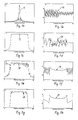
- the apparent discontinuities in the phase diagrams (fig. 1b, 1d, 1f, and 1h, respectively) are due to the fact that the phases are plotted only in the interval (- ⁇ , + ⁇ ).
- the effective field vector B eff B1 + ⁇ B0, where B1 is proportional to the amplitude of the exciting RF- field and B0 the component resulting from the static magnetic field to which the nuclear spin system is exposed, initially points towards the north pole, i. e. in the Z-direction, and gradually moves in the yz-plane towards the south pole, briefly coinciding with the y-axis only when the frequency of the exciting RF field passes resonance.
- Fig. 1a shows the amplitude response 11
- This pulse excitation results in an amplitude response 11 with a
- the apparent lack of symmetry in the phase response 16 is due to insufficient digitization. It is to be noted that the phase response 16 is essentially meaningless over much of the width shown in fig. 1b, since the amplitude 11 is negligible except in the vicinity of the RF carrier frequency.
- Fig. 1c shows the amplitude response 12, and fig. 1d phase response 17, following conventional chirp excitation in a NMR pulse experiment which was carried out in the manner of Delayre's original experiment.
- the carrier frequency of the RF exciting pulse was swept from 10 kHz to 40 kHz.
- Fig. 1e shows the amplitude profile obtained with a spin-echo sequence (90°- ⁇ -180°- ⁇ ′-acquisition) using, according to the invention, two chirp pulses (details will be given below).
- fig. 1f the corresponding phase response 19 is shown.
- the ripple 18 in the amplitude response 13 of fig. 1e is due to imperfect refocusing.
- the amplitude ⁇ B1 of the 90° chirp pulse(s) was 340 Hz
- the RF amplitude ⁇ B2 of the 180° chirp pulse(s) was 952 Hz.
- the second pulse 23 must be half as long as the first pulse 22, as illustrated in fig. 2a.
- the requirement that the two chirp pulses 22 and 23 should have different durations ⁇ 90 and ⁇ 180 can be understood from the following explanation: consider a magnetization vector precessing with a frequency ⁇ RFmin at the "lower" end 26 of the sweep, this vector will be brought into the transverse plane at the very beginning 29 of the experiment, and precess essentially freely during the interval ⁇ 90 + ⁇ .
- FIG. 2c A more accurate picture of the echo formation is given in fig. 2c, where the time-dependence of the phases of three typical magnetization vectors, at offsets of 75 Hz (dashed line 29), 150 Hz (solid line 31), and 200 Hz (dash-dotted line 32) with respect to the beginning of the sweep, is shown in the accelerating rotating frame described above.
- the sweep merely extends over 300 Hz.
- the time-derivative of a trajectory in Fig. 2c corresponds to the instantaneous offset frequency.
- the frequency at which the frame rotates is suddenly switched from ⁇ RFmax to ⁇ RFmin after the end of each pulse 22 and 23.
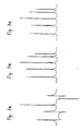
- Fig. 3a shows the conventional chirp spectrum obtained with Delayre's technique by sweeping once through the spectrum, recording the free induction decay after the end of the sweep, and Fourier transforming without any phase corrections.
- the signals appear between 14 and 17 kHz from the initial frequency of the sweep which runs from 0 to 30 kHz.
- the phases are so strongly frequency-dependent that a phase-correction is very difficult.
- Fig. 3b shows a spectrum of the same sample obtained with the chirp refocusing sequence 22, 23, where the pulse lengths of the 90° and 180° pulses 22 and 23 were 20 ms and 10 ms, respectively, and where the amplitudes had a ratio of about 1:3.
- the de- and refocusing intervals ⁇ and ⁇ ′ were 300 ⁇ s and 10.31 ms, respectively (the latter was optimized empirically to account for propagation delays in the receiver system). All signals are in pure absorption, although only a frequency-independent phase correction has been applied. The very small remaining phase imperfections can be further removed by using a four-step Exorcycle as explained above to obtain the spectrum as shown in fig. 3c, which is substantially free of phase-distortions.
- the frequency was swept by driving five decades of a binary-coded decimal (BCD) input of a Program Test Source PTS 500 frequency synthesizer with the output of a TTL counter driven by a 5 MHz clock frequency, which can be switched to 10 MHz for the refocusing pulse.
- the synthesizer output was swept in 20 or 10 ms from 400 to 500 kHz, divided by 10, added to 120 MHz and multiplied by three in the final amplifier, so that the final sweep covered 30 kHz from 360.120 to 360.150 MHz.
- the attentuation levels of the first and second pulses 22 and 23 were 11 and 0 dB, respectively.
- the actual ratio of the RF amplitude was about 1:3. The outcome of the experiment is not critically dependent on this ratio, particularly if "Exorcycle" is used.
- the proton spectra were recorded using the sturdy decoupler coil of a 10 mm carbon-13 probe as transmitter/ receiver coil.
- Chirp pulses appear to be very promising for covering large bandwidths, such as encountered in NMR at very high magnetic fields or in paramagnetic solutions.
- Installations enabling performance of the method according to the invention i. e. excitation of transverse magnetization by means of chirp pulses 22 and 23 will be of advantage in spectrometers adapted to perform two-dimensional exchange spectroscopy "NOESY”), correlation spectroscopy (“COSY”), heteronuclear correlation spectroscopy, and multiple-quantum spectroscopy which are sensitive to large offsets and also in NMR imaging experiments and especially in NMR-tomography.
- NOESY two-dimensional exchange spectroscopy
- COSY correlation spectroscopy
- heteronuclear correlation spectroscopy heteronuclear correlation spectroscopy
- multiple-quantum spectroscopy which are sensitive to large offsets and also in NMR imaging experiments and especially in NMR-tomography.
- the sequence of chirp pulses 22, 23, as shown in Fig. 2a is inverted, i.e., the 180°-pulse 23 of the pulse form shown in Fig. 2a is generated as the first pulse and, thereafter, the 90°pulse 22 of the pulse form shown in Fig. 2a is generated.
- This inverted sequence of chirp pulses is of interest if, e.g., a transverse magnetization is to be converted into a longitudinal magnetization.
Abstract
Description
- The invention relates to a method for exciting transverse magnetization in NMR-experiments by irradiating the nuclear spin-system, which is subjected to a magnetic field of high field strength, with a sequence of RF-pulses to provide for a - substantially - phase-distortionless excitation followed by a free induction decay resulting in a spin-echo signal used for further processing and evaluation in terms of the physical quantities or information of interest, said sequence of RF-pulses comprising a first RF-pulse providing for a 90°-flip, and a second RF-pulse, providing for a 180°-flip of the magnetization, each around an axis which is orthogonal to the direction of the magnetic field, the second RF-pulse being generated after elapse of a defocusing time interval τ following the first RF-pulse, as well as to NMR-spectroscopic devices which are operated by using the method according to the invention.
- A method of the above mentioned kind is known from the scientific publication by R. Freeman, S.P. Kempsell and M.H. Levitt, J. Magn. Reson. 38, 453 (1980).
- According to the known method, the transverse magnetization is excited by a "spin-knotting sequence" consisting of a group of three pulses, a 10° (X) pulse, a 60° (-X) pulse, and a 140° (X) pulse, separated by suitable intervals, seen in a reference frame, rotating about the Z-axis in synchronism with the transmitter frequency, where the static magnetic field is directed along the Z-axis, and the transverse magnetization aligned along the y-axis corresponds to an absorption mode signal.
- A somewhat larger bandwidth of the spectral range within which transverse magnetization can be excited is obtained by pulse modulation of a fixed frequency carrier in combination with phase modulation (R. Tycko, H.M. Cho, E. Schneider and A. Pines, J. Magnetic Reson. 61,
page 90, 1985), however, the improvement resulting therefrom is not of substantial importance. - Compared with usual practice to excite transverse magnetization in a NMR-experiment by merely applying a 90° pulse, the known methods provide for a considerable improvement with respect to phase-distortionless excitation. The bandwidth of the spectral range within which excitation of transverse magnetization is possible is, however, a comparably small interval, and the known methods, therefore suffer from the disadvantage that they are not effective to cover spectral ranges that are larger than the RF-amplitude, expressed in terms of the frequency ω = γB₁ which is equivalent to the field contribution of the exciting RF.
- The same holds for the situation prevailing in one- and multi-dimensional Fourier-Spectroscopy (R. R. Ernst, G. Bodenhausen and A. Wokaun, "Principles of Nuclear Magnetic Resonance in One and Two Dimensions", Clarendon Press, Oxford, 1987) according to which excitation in a frequency range of limited bandwidth is obtained by pulsed time modulation of a monochromatic transmitter-frequency.
- On the other hand as it is well known, in continuous-wave (CW) spectroscopy (R. R. Ernst, Adv. Magn. Reson. 2, 1 - 135 (1966) it is possible to sweep the exciting transmitter frequency over spectra with arbitrary width. CW-spectroscopy, however, requiring a "slow" frequency-sweep suffers from the disadvantage of very long measuring times and, therefore, tends to be largely supplanted by Fourier-Spectroscopy.
- If, to the object of reducing measuring time, continuous-wave spectra are recorded with a moderately fast frequency-sweep, one observes so-called "wiggles" in the spectra. In favourable cases, these artifacts my be removed by deconvolution (J. Dadok and R. F. Sprecher, J. Magn. Reson. 13, 243 - 248 (1974)), a method which has been called "Rapid Scan Fourier Transform Spectroscopy, by Gupta et al. (R. K. Gupta, J. A. Ferretti, and E.D. Becker, J. Magn. Reson. 13, 275 - 290 (1974)), since Fourier Transforms may be used very effectively to simplify the convolution integrals. In contrast to pulsed Fourier-Spectroscopy, however, the signal is recorded while the exciting RF-field is swept through the spectrum, exactly like in CW-spectroscopy.
- A completely different approach to rapid-scan spectroscopy has been introduced by Delayre (J. Delayre, U.S.-Patent No. 3,975,675), according to which the magnetization is first excited by a frequency-swept pulse, a so-called "chirp pulse", as it is well-known per se in ion cyclotron resonance (ICR), where chirped pulses are employed in routine measurements M.B. Comisarow und A. G. Marshall, Chem. Phys. Lett. 26, 489 (1974)), and their use has recently been extended to two- dimensional ICR spectroscopy (P. Pfändler, G. Bodenhausen, J. Rapin, M. E. Walser and T. Gäumann, J. Am. Chem. Soc. 110, 5625 - 5628 (1988)). In Delayre's experiment, in contrast to rapid-scan spectroscopy, the free induction decay is recorded after the end of the exciting chirp pulse. Due to the large frequency-dependent phase errors in the resulting spectra, Delayre's approach has never enjoyed much popularity in NMR.
- It is, therefore, a primary object of the invention to provide a method for exciting transverse magnetization in a NMR-pulse experiment enabling both, excitation in a substantially arbitrary frequency range, and reliable compensation of phase-dispersion of an acquired spin-echo signal.
- To this object, according to the invention, the first exciting pulse providing a 90° flip-angle, and the second exciting pulse, providing for a 180° flip-angle are chirp pulses within the duration of which the frequency of the exciting RF-pulse is swept in a monotonous relation with respect to time between a lower frequency ωRFmin and an upper limit frequency ωRFmax, the duration of the second chirp pulse is half the duration of the first chirp pulse, and the amplitude of the second chirp pulse is between 2 times and 4 times the amplitude of the first chirp pulse.
- By the chirp pulse sequence according to the invention the condition of a refocusing of the magnetization vectors to form a spin-echo is fulfilled, i. e., phase-distortions otherwise to be taken into account may be kept negligible over a very large bandwidth, the invention, therefore, combining the advantages of pulse spectroscopy techniques with those of CW spectroscopy.
- The method according to the invention not being very sensitive to the amplitude of the second chirp pulse, most practical cases are covered by choosing for the ratio A 180°/A 90° a value between 2 and 4.
- Acquisition of free induction decay signal following the second chirp pulse may be started immediately at the trailing edge of this pulse or, as it is preferable in some cases, at maximum intensity of the spin-echo signal in which case a spectrum obtained by Fourier transformation of the echo signal is essentially free of phase-dispersion.
- In usual cases, the frequency sweep of the RF exciting radiation is linear with respect to time. In special cases it might be helpful, however, to provide for a non-linear but monotonous frequency sweep between the limiting frequencies ωRFmin and ωRF max.
- In a preferred performance of the method according to the invention a four-step sequence of 90°-180° chirp pulse pairs is generated wherein the phase of the 90° pulse is the same as that of the RF-carrier frequency whereas the phase of the 180° chirp pulse is cycled through, 0°, 90°, 180° and 270° with respect to the phase of the RF-carrier frequency, and the phase of the receiver reference signal is alternately switched between 0° and 180° with respect to the phase of the RF-carrier frequency.
- In this mode of performance of the method according to the invention a most effective elimination of any phase-dispersion is achieved.
- The invention being useful for a variety of NMR pulse spectroscopy applications such as two-dimensional exchange spectroscopy, correlation spectroscopy, heteronuclear correlation spectroscopy, and multiple-quantum spectroscopy, it is understood that NMR pulse spectrometers having the said spectroscopic capabilities and being equipped with an installation enabling an operation mode in accordance with the invention are also regarded as subject matter of the invention.
- Further details, aspects and advantages of the invention will be apparent from the following description of the invention with reference to the drawing wherein
- Fig. 1a shows the amplitude response for a conventional monochromatic 90° pulse,
- Fig. 1b the phase response of a conventional monochromatic 90° pulse,
- Fig. 1c the amplitude response following conventional chirp excitation,
- Fig. 1d the phase response following conventional chirp excitation,
- Fig. 1e the amplitude profile obtained with a spin-echo sequence using two chirp pulses,
- Fig. 1f the phase response resulting from excitation by two chirp pulses,
- Fig. 1g the amplitude response of an excitation by a chirp echo sequence in combination with a four-step phase-cycling in the manner of "Exorcycle",
- Fig. 1h the phase response obtained by refocused chirp excitation combined with Exorcycle,
- Fig. 2a the time-dependence of the RF amplitude of a typical chirp refocusing pulse sequence,
- Fig. 2b the time-dependence of the RF-frequency for a typical chirp refocusing sequence,
- Fig. 2c the time-dependence of the phases of three magnetization vectors at offsets of 75, 150 and 200 Hz with respect to the beginning of the sweep in a simulation which for the sake of clarity merely extends over 300 Hz,
- Fig. 3a a proton spectrum of a mixture of chloroform, methylenechloride, acetone, cyclohexane and dioxane, obtained after excitation by a single chirp pulse,
- Fig. 3b a spectrum of the same mixture of substances obtained with a chirp refocusing sequence, and
- Fig. 3c a spectrum like that of the Fig. 3b, but with a four-step Exorcycle to remove small phase imperfections.
- Fig. 1a, 1c, 1e, and 1g show the offset dependence of the magnitude of the transverse magnetization, i. e. Mxy = (Mx² + My²)1/2, for a variety of NMR pulse experiments. For these experiments the fig. 1b, 1d, 1f, and 1h, respectively, show the offset dependence of the phase φ =arctan (My / Mx) of the transverse magnetization as represented by fig. 1a-1g, calculated for that moment at which the signal acquisition must be initiated (either immediately after the RF pulse or at the time of the spin-echo). The apparent discontinuities in the phase diagrams (fig. 1b, 1d, 1f, and 1h, respectively) are due to the fact that the phases are plotted only in the interval (-π, +π).
- The
amplitude responses
ωRF (t) = ωRFmin + ΔωRF·t/τρ,
wherein ΔωRF min is the minimum frequency used to excite a transverse magnetization, ΔωRFis the range of the frequency sweep, and τρ is the duration of the chirp pulse. ln the said rotating frame, the effective field vector Beff = B₁ + ΔB₀, where B₁ is proportional to the amplitude of the exciting RF- field and B₀ the component resulting from the static magnetic field to which the nuclear spin system is exposed, initially points towards the north pole, i. e. in the Z-direction, and gradually moves in the yz-plane towards the south pole, briefly coinciding with the y-axis only when the frequency of the exciting RF field passes resonance. - Fig. 1a shows the
amplitude response 11, and Fig. 1b thephase response 16 for a conventional monochromatic 90° exciting pulse with a carrier frequency of 25 kHz, a RF amplitude γB₁ = 340 Hz and a duration τρ = 750 µs, wherein the RF amplitude is expressed in terms of the gyromagnetic ratio γ and the field strength B₁ of the exciting pulse. This pulse excitation results in anamplitude response 11 with a |sinω/ω| envelope in the frequency domain and a very steep frequency-dependent phase error. The apparent lack of symmetry in thephase response 16 is due to insufficient digitization. It is to be noted that thephase response 16 is essentially meaningless over much of the width shown in fig. 1b, since theamplitude 11 is negligible except in the vicinity of the RF carrier frequency. - Fig. 1c shows the
amplitude response 12, and fig.1d phase response 17, following conventional chirp excitation in a NMR pulse experiment which was carried out in the manner of Delayre's original experiment. The carrier frequency of the RF exciting pulse was swept from 10 kHz to 40 kHz. The intensity of the exciting pulse was the same as that of the pulse used in the experiment according to figs. 1a and 1b ( γB₁ = 340 Hz), and the pulse duration τρ was 2 ms. These conditions were just chosen such that the magnetization was tipped from the north pole to the equatorial plane of the rotating frame, in analogy to the effect of a normal 90° pulse. Theerratic response 17 according to fig. 1d represents the phases of the signals in a spectrum obtained by Fourier transformation of a free induction decay acquired immediately after the end of the exciting pulse. It is seen that the frequency-dependence of the phase is so "steep" that a phase correction would be difficult. - Fig. 1e shows the amplitude profile obtained with a spin-echo sequence (90°-τ -180°- τ′-acquisition) using, according to the invention, two chirp pulses (details will be given below). In fig. 1f the
corresponding phase response 19 is shown. - The
ripple 18 in the amplitude response 13 of fig. 1e is due to imperfect refocusing. - This problem can be largely removed by generating chirp echo sequences according to the invention in a four-step phase-cycle in a manner known per se as "Exorcycle" (G. Bodenhausen, R. Freeman, and D. L. Turner, J. Magn. Reson. 27, 511 - 514 (1977), i. e. by incrementing the initial phase of the second chirp pulse in steps of π/2, and alternately adding and subtracting the signals. This procedure yields the
smooth amplitude response 14 of fig. 1g and the phase response 21 of fig. 1h, which shows that the phase dispersion can be largely eliminated by combining refocusing and phase-cycling. To more completely explain the Exorcycle-method as used in combination with the invention, reference is made to the following table "chirp pulse refocusing + Exorcycle" showing for a sequence of four chirp pulse excitations the phase angles of the 90° chirp pulse, and of the receiver reference signal, each of which relative to the phase angle of the carrier frequency. - By adding the amplitude responses of the four chirp pulse echo sequences as listed in the table, the
smooth amplitude response 14 of fig. 1g is obtained.Table: Chirp pulse refocusing + "Exorcycle" Chirp echo sequence phase shift with respect to carrier frequency 90° chirp pulse 180° chirp pulse receiver reference (a) 0° 0° 0° (b) 0° 90° 180° (c) 0° 180° 0° (d) 0° 270° 180° - For the calculations shown in Fig. 1 the amplitude γB₁ of the 90° chirp pulse(s) was 340 Hz, and the RF amplitude γB₂ of the 180° chirp pulse(s) was 952 Hz.
- To more fully explain the chirp pulse excitation according to the invention, reference is next made to the details of fig. 2a, 2b, and 2c:
- If chirp pulses, generally designated in fig. 2 as 22 and 23, are used in echo sequences, the
second pulse 23 must be half as long as thefirst pulse 22, as illustrated in fig. 2a. The condition that the duration τ¹⁸⁰ of thesecond chirp pulse 23 is half the duration τ⁹⁰ of the first chirp pulse 22 (τ¹⁸⁰ = τ⁹⁰/2) implies that within the second pulse the frequency must be swept twice as fast as within thefirst pulse 22, as shown schematically in fig. 2b in which, on the same time base as that of fig. 2a the frequency of the chirp pulses is represented by the ordinate. As it is shown in fig. 2a an echo signal is formed at time τ′ = τ+ τ¹⁸⁰ after the trailingedge 24 of thesecond chirp pulse 23. - As shown in fig. 2a, the defocusing interval τ can be very short (τ= 300 µs in both experiments and simulations). The requirement that the two
chirp pulses end 26 of the sweep, this vector will be brought into the transverse plane at the very beginning 29 of the experiment, and precess essentially freely during the interval τ⁹⁰ + τ. It will be affected by thesecond pulse 23 at itsvery beginning 30 and will then need a time τ⁹⁰ + τ to refocus, so as to contribute to theecho 25 at a time τ′ = τ⁹⁰ + τ-τ¹⁸⁰ after theend 24 of thesecond pulse 23. On the other hand, a vector with a frequency ω RFmax at the "upper" end 27 of the sweep will only be brought into the transverse plane at theend 28 of thefirst pulse 22, and then defocus for a time τ + τ¹⁸⁰, since it will only be affected by the trailingedge 24 of thesecond pulse 23. This vector will therefore refocus at a time τ¹⁸⁰ + τ after theend 24 of the second pulse. The two echo contributions will be synchronized provided
τ¹⁸⁰ = τ⁹⁰/2. - A more accurate picture of the echo formation is given in fig. 2c, where the time-dependence of the phases of three typical magnetization vectors, at offsets of 75 Hz (dashed line 29), 150 Hz (solid line 31), and 200 Hz (dash-dotted line 32) with respect to the beginning of the sweep, is shown in the accelerating rotating frame described above. For the sake of clarity, in the simulation represented by fig. 2c, the sweep merely extends over 300 Hz. The time-derivative of a trajectory in Fig. 2c corresponds to the instantaneous offset frequency. The frequency at which the frame rotates is suddenly switched from ωRFmax to ωRFmin after the end of each
pulse trajectories trajectories echo 25, where the acquisition of the signal is started. - If frequency-swept
pulses 22 and 23 - chirp pulses - are used it is not sufficient to double the RF amplitude to double the effective flip angle. Thus if a value γ B₁⁹⁰ is required for a pulse of length τρ to achieve a rotation Iz→Ix, the value γ B₁¹⁸⁰ required for adiabatic inversion (Iz→-Iz) in the same duration τρ must be about three times larger γB₁¹⁸⁰ ≈ 3 γ B¹⁹⁰). To optimize the conditions for refocusing (e. g. for converting Ix→-Ix), numerical simulations have been carried out. For thepulse sequence second pulse 23 must have an amplitude of 2.8 times the amplitude of the first pulse. - To compare chirp spectroscopy with and without refocusing, proton spectra of a mixture of chloroform, methylene chloride, acetone, cyclohexane, and dioxane were recorded with a modified Bruker WH 360 spectrometer. Fig. 3a shows the conventional chirp spectrum obtained with Delayre's technique by sweeping once through the spectrum, recording the free induction decay after the end of the sweep, and Fourier transforming without any phase corrections. The signals appear between 14 and 17 kHz from the initial frequency of the sweep which runs from 0 to 30 kHz. The phases are so strongly frequency-dependent that a phase-correction is very difficult.
- Fig. 3b shows a spectrum of the same sample obtained with the
chirp refocusing sequence pulses - The frequency was swept by driving five decades of a binary-coded decimal (BCD) input of a Program Test Source PTS 500 frequency synthesizer with the output of a TTL counter driven by a 5 MHz clock frequency, which can be switched to 10 MHz for the refocusing pulse. The synthesizer output was swept in 20 or 10 ms from 400 to 500 kHz, divided by 10, added to 120 MHz and multiplied by three in the final amplifier, so that the final sweep covered 30 kHz from 360.120 to 360.150 MHz. Using the proton decoupler of a Bruker WH 360 spectrometer, the attentuation levels of the first and
second pulses - Chirp pulses appear to be very promising for covering large bandwidths, such as encountered in NMR at very high magnetic fields or in paramagnetic solutions.
- Installations enabling performance of the method according to the invention, i. e. excitation of transverse magnetization by means of
chirp pulses - According to an analoguous modification of the method according to the invention, the sequence of
chirp pulses pulse 23 of the pulse form shown in Fig. 2a is generated as the first pulse and, thereafter, the 90°pulse 22 of the pulse form shown in Fig. 2a is generated. - This inverted sequence of chirp pulses is of interest if, e.g., a transverse magnetization is to be converted into a longitudinal magnetization.
- It is intended such a modification also belonging to the subject matter of the invention and being comprised by the scope of the claims.
Claims (11)
wherein the first exciting pulse (22) and the second exciting pulse (23) are chirp pulses within the duration of which the frequency of the exciting RF-energy is swept in a monotonous relation with respect to time between a lower limit frequency ωRFmin to an upper limit frequency
ωRFmax
the duration τ180° of the second chirp pulse (23) is half the duration τ90° of the first chirp pulse (22), and the amplitude of the second chirp pulse (23) is between 2 and 4 times the amplitude of the first chirp pulse (22).
in the first acquisition cycle (a) the second chirp pulse (23) being generated with a zero-phase shift with respect to the carrier frequency, and the receiver being operated also with a zero-phase shift between the pulse carrier frequency and the receiver reference signal, in the second acquisition cycle (b) the second chirp pulse (23) being genereated with a 90° phase shift with respect to the carrier frequency, and the receiver being operated with a 180° phase shift between the carrier frequency and the receiver reference signal,
in the third acquisition cycle (c) the second chirp pulse (23) being generated with a 180° phase shift with respect to the carrier frequency, and the receiver being operated again at zero-phase shift between the carrier frequency and the receiver reference signal,
and in the forth aquisition cycle (d) the second chirp pulse (23) being generated with a 270b-phase shift with respect to the carrier frequency, and the receiver being operated again with a 180°-phase shift between the carrier frequency and the receiver reference signal, the first chirp pulses (22) always being generated with a zero-phase shift with respect to the carrier frequency,
and wherein the acquisitions obtained by the four acquisition cycles (a, b, c and d) are added, and the sum of these acquisitions is used for further processing and evaluation.
Priority Applications (4)
| Application Number | Priority Date | Filing Date | Title |
|---|---|---|---|
| EP89107303A EP0394504B1 (en) | 1989-04-22 | 1989-04-22 | A method for exciting transverse magnetization in NMR pulse experiments |
| DE68914440T DE68914440T2 (en) | 1989-04-22 | 1989-04-22 | Method for excitation of the transverse magnetization in magnetic nuclear magnetic resonance pulse experiments. |
| US07/511,627 US5126671A (en) | 1989-04-22 | 1990-04-20 | Method for exciting transverse magnetization in nmr pulse experiments |
| JP2107297A JPH0736007B2 (en) | 1989-04-22 | 1990-04-23 | Method for exciting transverse magnetization in NMR pulse experiments |
Applications Claiming Priority (1)
| Application Number | Priority Date | Filing Date | Title |
|---|---|---|---|
| EP89107303A EP0394504B1 (en) | 1989-04-22 | 1989-04-22 | A method for exciting transverse magnetization in NMR pulse experiments |
Publications (2)
| Publication Number | Publication Date |
|---|---|
| EP0394504A1 true EP0394504A1 (en) | 1990-10-31 |
| EP0394504B1 EP0394504B1 (en) | 1994-04-06 |
Family
ID=8201272
Family Applications (1)
| Application Number | Title | Priority Date | Filing Date |
|---|---|---|---|
| EP89107303A Expired - Lifetime EP0394504B1 (en) | 1989-04-22 | 1989-04-22 | A method for exciting transverse magnetization in NMR pulse experiments |
Country Status (4)
| Country | Link |
|---|---|
| US (1) | US5126671A (en) |
| EP (1) | EP0394504B1 (en) |
| JP (1) | JPH0736007B2 (en) |
| DE (1) | DE68914440T2 (en) |
Cited By (8)
| Publication number | Priority date | Publication date | Assignee | Title |
|---|---|---|---|---|
| EP0601229A1 (en) * | 1992-12-09 | 1994-06-15 | Spectrospin Ag | A method for exciting transverse magnetisation in magnetic resonance |
| WO1995003551A1 (en) * | 1993-07-26 | 1995-02-02 | The Government Of The United States Of America, Represented By The Secretary Of The Department Of Health And Human Services | Pulsed low frequency epr spectrometer and imager |
| WO1995009368A1 (en) * | 1993-09-27 | 1995-04-06 | British Technology Group Limited | Apparatus for and method of nuclear resonance testing |
| US5726569A (en) * | 1995-03-30 | 1998-03-10 | Siemens Aktiengesellschaft | Method and apparatus for acquiring image data in a nuclear magnetic resonance tomography system |
| US5828216A (en) * | 1996-08-19 | 1998-10-27 | The United States Of America As Represented By The Department Of Health And Human Services | Gated RF preamplifier for use in pulsed radiofrequency electron paramagnetic resonance and MRI |
| US5865746A (en) * | 1995-07-20 | 1999-02-02 | The United States Of America As Represented By The Department Of Health And Human Services | In vivo imaging and oxymetry by pulsed radiofrequency paramagnetic resonance |
| US6091240A (en) * | 1994-09-29 | 2000-07-18 | Btg International Limited | Method of nuclear quadrupole resonance testing and method of configuring apparatus for nuclear quadrupole resonance testing |
| CN107871650A (en) * | 2016-09-27 | 2018-04-03 | 中国科学院生态环境研究中心 | Excitation state dichloromethane protonating agent |
Families Citing this family (5)
| Publication number | Priority date | Publication date | Assignee | Title |
|---|---|---|---|---|
| DE3940633A1 (en) * | 1989-12-08 | 1991-06-13 | Spectrospin Ag | GAUSS-IMPULS-KASCADE |
| US5581182A (en) * | 1995-07-19 | 1996-12-03 | Florida State University | Method and apparatus for broadband decoupling in nuclear magnetic resonance with chirp pulses |
| US6268728B1 (en) * | 1999-02-10 | 2001-07-31 | Board Of Trustees Of The Leland Stanford Junior University | Phase-sensitive method of radio-frequency field mapping for magnetic resonance imaging |
| AU2003224940A1 (en) * | 2002-04-12 | 2003-10-27 | California Institute Of Technology | System and method of magnetic resonance imaging |
| US7598738B2 (en) * | 2008-03-07 | 2009-10-06 | Varian, Inc. | Complete structure elucidation of molecules utilizing single NMR experiment |
Citations (3)
| Publication number | Priority date | Publication date | Assignee | Title |
|---|---|---|---|---|
| US3975675A (en) * | 1974-02-05 | 1976-08-17 | Compagnie D'applications Mecaniques A L'electronique Au Cinema Et A L'atomistique (C.A.M.E.C.A.) | Impulse response magnetic resonance spectrometer |
| US4345207A (en) * | 1980-04-24 | 1982-08-17 | The United States Of America As Represented By The Secretary Of The Navy | Method and apparatus for obtaining enhanced NMR signals |
| EP0195404A2 (en) * | 1985-03-21 | 1986-09-24 | General Electric Company | Methods of, and apparatus for, proton decoupling in nuclear magnetic resonance spectroscopy |
Family Cites Families (4)
| Publication number | Priority date | Publication date | Assignee | Title |
|---|---|---|---|---|
| US4695799A (en) * | 1985-06-18 | 1987-09-22 | General Electric Company | NMR magnetization inversion by non-linear adiabatic fast passage |
| WO1988000699A1 (en) * | 1986-07-11 | 1988-01-28 | Thomson-Cgr | Radio-frequency energization method in an nmr experiment |
| GB8715302D0 (en) * | 1987-06-30 | 1987-08-05 | Ordidge R J | Nmr spectroscopy |
| US4985677A (en) * | 1989-06-22 | 1991-01-15 | The Board Of Trustees Of The Leland Stanford Junior University | Magnetic resonance imaging and spectroscopy using an excitation pulse for multiple-dimensional selectivity |
-
1989
- 1989-04-22 EP EP89107303A patent/EP0394504B1/en not_active Expired - Lifetime
- 1989-04-22 DE DE68914440T patent/DE68914440T2/en not_active Expired - Lifetime
-
1990
- 1990-04-20 US US07/511,627 patent/US5126671A/en not_active Expired - Lifetime
- 1990-04-23 JP JP2107297A patent/JPH0736007B2/en not_active Expired - Fee Related
Patent Citations (3)
| Publication number | Priority date | Publication date | Assignee | Title |
|---|---|---|---|---|
| US3975675A (en) * | 1974-02-05 | 1976-08-17 | Compagnie D'applications Mecaniques A L'electronique Au Cinema Et A L'atomistique (C.A.M.E.C.A.) | Impulse response magnetic resonance spectrometer |
| US4345207A (en) * | 1980-04-24 | 1982-08-17 | The United States Of America As Represented By The Secretary Of The Navy | Method and apparatus for obtaining enhanced NMR signals |
| EP0195404A2 (en) * | 1985-03-21 | 1986-09-24 | General Electric Company | Methods of, and apparatus for, proton decoupling in nuclear magnetic resonance spectroscopy |
Non-Patent Citations (4)
| Title |
|---|
| JOURNAL OF MAGNETIC RESONANCE, vol. 35, 1979, pages 19-37, Academic Press, Inc., New York, US; V.J. BASUS et al.: "Utilization of chirp frequency modulation with 180 degrees-phase modulation for heteronuclear spin decoupling" * |
| JOURNAL OF MAGNETIC RESONANCE, vol. 61, 1985, pages 90-101, Academic Press Inc., New York, US; R. TYCKO et al.: "Composite pulses without phase distortion" * |
| JOURNAL OF THE AMERICAN CHEMICAL SOCIETY, vol. 110, 1988, pages 5625-5628, American Chemical Society, Gaston, PA, US; P. PFÄNDLER et al.: "Broad-band two-dimensional fourier transform ion cyclotron resonance" * |
| PATENT ABSTRACTS OF JAPAN, vol. 9, no. 167 (P-372)[1890], 12th July 1985; & JP-A-60 044 880 (YOKOKAWA MEDICAL SYSTEM K.K.) 11-03-1985 * |
Cited By (12)
| Publication number | Priority date | Publication date | Assignee | Title |
|---|---|---|---|---|
| EP0601229A1 (en) * | 1992-12-09 | 1994-06-15 | Spectrospin Ag | A method for exciting transverse magnetisation in magnetic resonance |
| US5448170A (en) * | 1992-12-09 | 1995-09-05 | Spectrospin Ag | Method for exciting transverse magnetization in magnetic resonance |
| WO1995003551A1 (en) * | 1993-07-26 | 1995-02-02 | The Government Of The United States Of America, Represented By The Secretary Of The Department Of Health And Human Services | Pulsed low frequency epr spectrometer and imager |
| US5502386A (en) * | 1993-07-26 | 1996-03-26 | The United States Of America As Represented By The Department Of Health And Human Services | Pulsed low frequency EPR spectrometer and imager |
| WO1995009368A1 (en) * | 1993-09-27 | 1995-04-06 | British Technology Group Limited | Apparatus for and method of nuclear resonance testing |
| US5814987A (en) * | 1993-09-27 | 1998-09-29 | British Technology Group Limited | Apparatus for and method of nuclear resonance testing |
| US6091240A (en) * | 1994-09-29 | 2000-07-18 | Btg International Limited | Method of nuclear quadrupole resonance testing and method of configuring apparatus for nuclear quadrupole resonance testing |
| US6222364B1 (en) | 1994-09-29 | 2001-04-24 | Btg International Limited | Method of nuclear quadrupole resonance testing and method of configuring apparatus for nuclear quadrupole resonance testing |
| US5726569A (en) * | 1995-03-30 | 1998-03-10 | Siemens Aktiengesellschaft | Method and apparatus for acquiring image data in a nuclear magnetic resonance tomography system |
| US5865746A (en) * | 1995-07-20 | 1999-02-02 | The United States Of America As Represented By The Department Of Health And Human Services | In vivo imaging and oxymetry by pulsed radiofrequency paramagnetic resonance |
| US5828216A (en) * | 1996-08-19 | 1998-10-27 | The United States Of America As Represented By The Department Of Health And Human Services | Gated RF preamplifier for use in pulsed radiofrequency electron paramagnetic resonance and MRI |
| CN107871650A (en) * | 2016-09-27 | 2018-04-03 | 中国科学院生态环境研究中心 | Excitation state dichloromethane protonating agent |
Also Published As
| Publication number | Publication date |
|---|---|
| JPH0736007B2 (en) | 1995-04-19 |
| JPH03205577A (en) | 1991-09-09 |
| EP0394504B1 (en) | 1994-04-06 |
| DE68914440D1 (en) | 1994-05-11 |
| US5126671A (en) | 1992-06-30 |
| DE68914440T2 (en) | 1994-07-28 |
Similar Documents
| Publication | Publication Date | Title |
|---|---|---|
| Smallcombe et al. | WET solvent suppression and its applications to LC NMR and high-resolution NMR spectroscopy | |
| Mueller | Sensitivity enhanced detection of weak nuclei using heteronuclear multiple quantum coherence | |
| Gromov et al. | A Q-band pulse EPR/ENDOR spectrometer and the implementation of advanced one-and two-dimensional pulse EPR methodology | |
| US4345207A (en) | Method and apparatus for obtaining enhanced NMR signals | |
| EP0394504B1 (en) | A method for exciting transverse magnetization in NMR pulse experiments | |
| US6184683B1 (en) | Method to improve resolution of two-dimensional heteronuclear correlation spectra in solid-state NMR | |
| US4443761A (en) | NMR Spectroscopy | |
| US6888348B2 (en) | Decoupling sideband resolved NMR spectroscopy (desire) | |
| EP0170508B1 (en) | Method and apparatus for obtaining nuclear magnetic resonance spectra | |
| US7042214B2 (en) | Non-linear symmetric sweep spectral-spatial RF pulses for MR spectroscopy | |
| EP0538255B1 (en) | Multiple-quantum nmr with frequency-modulated chirp pulses | |
| US5926023A (en) | Method of improving the resolution in two-dimensional heteronuclear correlation spectra of solid state NMR | |
| US5798643A (en) | Method for operating an NMR tomography apparatus suitable for use with a chronologically constant basic magnetic field inhomogeneity | |
| US4728889A (en) | Spectroscopy method | |
| GB2176012A (en) | Nuclear magnetic resonance imaging apparatus | |
| US5099206A (en) | Nuclear magnetic resonance spectroscopy | |
| Stoll | Pulse EPR | |
| Hubrich et al. | The generalized hyperfine sublevel coherence transfer experiment in one and two dimensions | |
| JPS6134451A (en) | Method of exciting sample for nuclear magnetic resonance tomography | |
| McKinnon et al. | A one‐shot lactate‐editing sequence for localized whole‐body spectroscopy | |
| US5448170A (en) | Method for exciting transverse magnetization in magnetic resonance | |
| Jeschke et al. | Time‐domain chirp electron nuclear double resonance spectroscopy in one and two dimensions | |
| Roumestand et al. | The use of band filtering in multidimensional NMR. Evaluation of two “user-friendly” techniques | |
| US5243285A (en) | Method and arrangement for two-dimensional nuclear magnetic resonance spectroscopy | |
| US4703268A (en) | Clean multiple echo magnetic resonance imaging using asymmetric sequences |
Legal Events
| Date | Code | Title | Description |
|---|---|---|---|
| PUAI | Public reference made under article 153(3) epc to a published international application that has entered the european phase |
Free format text: ORIGINAL CODE: 0009012 |
|
| 17P | Request for examination filed |
Effective date: 19900302 |
|
| AK | Designated contracting states |
Kind code of ref document: A1 Designated state(s): CH DE FR GB LI NL |
|
| 17Q | First examination report despatched |
Effective date: 19930914 |
|
| GRAA | (expected) grant |
Free format text: ORIGINAL CODE: 0009210 |
|
| AK | Designated contracting states |
Kind code of ref document: B1 Designated state(s): CH DE FR GB LI NL |
|
| PG25 | Lapsed in a contracting state [announced via postgrant information from national office to epo] |
Ref country code: NL Effective date: 19940406 |
|
| REF | Corresponds to: |
Ref document number: 68914440 Country of ref document: DE Date of ref document: 19940511 |
|
| ET | Fr: translation filed | ||
| NLV1 | Nl: lapsed or annulled due to failure to fulfill the requirements of art. 29p and 29m of the patents act | ||
| PLBE | No opposition filed within time limit |
Free format text: ORIGINAL CODE: 0009261 |
|
| STAA | Information on the status of an ep patent application or granted ep patent |
Free format text: STATUS: NO OPPOSITION FILED WITHIN TIME LIMIT |
|
| 26N | No opposition filed | ||
| REG | Reference to a national code |
Ref country code: GB Ref legal event code: IF02 |
|
| REG | Reference to a national code |
Ref country code: CH Ref legal event code: PFA Free format text: SPECTROSPIN AG TRANSFER- BRUKER BIOSPIN AG |
|
| REG | Reference to a national code |
Ref country code: FR Ref legal event code: CD |
|
| PGFP | Annual fee paid to national office [announced via postgrant information from national office to epo] |
Ref country code: FR Payment date: 20060425 Year of fee payment: 18 |
|
| PGFP | Annual fee paid to national office [announced via postgrant information from national office to epo] |
Ref country code: GB Payment date: 20060428 Year of fee payment: 18 |
|
| PGFP | Annual fee paid to national office [announced via postgrant information from national office to epo] |
Ref country code: CH Payment date: 20060630 Year of fee payment: 18 |
|
| REG | Reference to a national code |
Ref country code: CH Ref legal event code: PL |
|
| GBPC | Gb: european patent ceased through non-payment of renewal fee |
Effective date: 20070422 |
|
| PG25 | Lapsed in a contracting state [announced via postgrant information from national office to epo] |
Ref country code: LI Free format text: LAPSE BECAUSE OF NON-PAYMENT OF DUE FEES Effective date: 20070430 Ref country code: CH Free format text: LAPSE BECAUSE OF NON-PAYMENT OF DUE FEES Effective date: 20070430 |
|
| PG25 | Lapsed in a contracting state [announced via postgrant information from national office to epo] |
Ref country code: GB Free format text: LAPSE BECAUSE OF NON-PAYMENT OF DUE FEES Effective date: 20070422 |
|
| PG25 | Lapsed in a contracting state [announced via postgrant information from national office to epo] |
Ref country code: FR Free format text: LAPSE BECAUSE OF NON-PAYMENT OF DUE FEES Effective date: 20070430 |
|
| PGFP | Annual fee paid to national office [announced via postgrant information from national office to epo] |
Ref country code: DE Payment date: 20080429 Year of fee payment: 20 |