EP0400489A2 - Locating system, in particular for underground working - Google Patents
Locating system, in particular for underground working Download PDFInfo
- Publication number
- EP0400489A2 EP0400489A2 EP90109919A EP90109919A EP0400489A2 EP 0400489 A2 EP0400489 A2 EP 0400489A2 EP 90109919 A EP90109919 A EP 90109919A EP 90109919 A EP90109919 A EP 90109919A EP 0400489 A2 EP0400489 A2 EP 0400489A2
- Authority
- EP
- European Patent Office
- Prior art keywords
- transmitter
- location
- location system
- remote control
- locating
- Prior art date
- Legal status (The legal status is an assumption and is not a legal conclusion. Google has not performed a legal analysis and makes no representation as to the accuracy of the status listed.)
- Withdrawn
Links
Images


Classifications
-
- A—HUMAN NECESSITIES
- A62—LIFE-SAVING; FIRE-FIGHTING
- A62B—DEVICES, APPARATUS OR METHODS FOR LIFE-SAVING
- A62B99/00—Subject matter not provided for in other groups of this subclass
-
- A—HUMAN NECESSITIES
- A63—SPORTS; GAMES; AMUSEMENTS
- A63B—APPARATUS FOR PHYSICAL TRAINING, GYMNASTICS, SWIMMING, CLIMBING, OR FENCING; BALL GAMES; TRAINING EQUIPMENT
- A63B29/00—Apparatus for mountaineering
- A63B29/02—Mountain guy-ropes or accessories, e.g. avalanche ropes; Means for indicating the location of accidentally buried, e.g. snow-buried, persons
- A63B29/021—Means for indicating the location of accidentally buried, e.g. snow-buried, persons
-
- F—MECHANICAL ENGINEERING; LIGHTING; HEATING; WEAPONS; BLASTING
- F16—ENGINEERING ELEMENTS AND UNITS; GENERAL MEASURES FOR PRODUCING AND MAINTAINING EFFECTIVE FUNCTIONING OF MACHINES OR INSTALLATIONS; THERMAL INSULATION IN GENERAL
- F16P—SAFETY DEVICES IN GENERAL; SAFETY DEVICES FOR PRESSES
- F16P3/00—Safety devices acting in conjunction with the control or operation of a machine; Control arrangements requiring the simultaneous use of two or more parts of the body
- F16P3/12—Safety devices acting in conjunction with the control or operation of a machine; Control arrangements requiring the simultaneous use of two or more parts of the body with means, e.g. feelers, which in case of the presence of a body part of a person in or near the danger zone influence the control or operation of the machine
- F16P3/14—Safety devices acting in conjunction with the control or operation of a machine; Control arrangements requiring the simultaneous use of two or more parts of the body with means, e.g. feelers, which in case of the presence of a body part of a person in or near the danger zone influence the control or operation of the machine the means being photocells or other devices sensitive without mechanical contact
- F16P3/147—Safety devices acting in conjunction with the control or operation of a machine; Control arrangements requiring the simultaneous use of two or more parts of the body with means, e.g. feelers, which in case of the presence of a body part of a person in or near the danger zone influence the control or operation of the machine the means being photocells or other devices sensitive without mechanical contact using electro-magnetic technology, e.g. tags or radar
-
- G—PHYSICS
- G01—MEASURING; TESTING
- G01S—RADIO DIRECTION-FINDING; RADIO NAVIGATION; DETERMINING DISTANCE OR VELOCITY BY USE OF RADIO WAVES; LOCATING OR PRESENCE-DETECTING BY USE OF THE REFLECTION OR RERADIATION OF RADIO WAVES; ANALOGOUS ARRANGEMENTS USING OTHER WAVES
- G01S13/00—Systems using the reflection or reradiation of radio waves, e.g. radar systems; Analogous systems using reflection or reradiation of waves whose nature or wavelength is irrelevant or unspecified
- G01S13/74—Systems using reradiation of radio waves, e.g. secondary radar systems; Analogous systems
- G01S13/76—Systems using reradiation of radio waves, e.g. secondary radar systems; Analogous systems wherein pulse-type signals are transmitted
- G01S13/767—Responders; Transponders
Landscapes
- Engineering & Computer Science (AREA)
- Radar, Positioning & Navigation (AREA)
- Remote Sensing (AREA)
- Health & Medical Sciences (AREA)
- General Engineering & Computer Science (AREA)
- General Health & Medical Sciences (AREA)
- Physics & Mathematics (AREA)
- General Physics & Mathematics (AREA)
- Business, Economics & Management (AREA)
- Emergency Management (AREA)
- Pulmonology (AREA)
- Physical Education & Sports Medicine (AREA)
- Computer Networks & Wireless Communication (AREA)
- Mechanical Engineering (AREA)
- Radar Systems Or Details Thereof (AREA)
- Selective Calling Equipment (AREA)
Abstract
Description
Die Erfindung betrifft ein Ortungssystem, insbesondere für den untertägigen Bergbau, mit einem von einer zu ortenden Person zu tragenden Ortungssender und einem von einer suchenden Person od. dgl. zu tragenden Ortungsempfänger, wobei vom Ortungssender ausgesandte elektromagnetische Wellen vom Ortungsempfänger empfangen und ortungstechnisch ausgewertet werden, wobei der Ortungssender im Bedarfsfalle einschaltbar und zu gegebener Zeit auch wieder ausschaltbar ist.The invention relates to a location system, in particular for underground mining, with a location transmitter to be carried by a person to be located and a location receiver to be carried by a searching person or the like, electromagnetic waves emitted by the location transmitter being received by the location receiver and evaluated in terms of location technology, the location transmitter can be switched on if necessary and can also be switched off again at the appropriate time.
Das aus der Praxis bekannte Ortungssystem, von dem die Erfindung ausgeht, ist für den untertägigen Bergbau bestimmt und weist zunächst einen von einer zu ortenden Person getragenen, nämlich dort beispielsweise in das Gehäuse des Kopflampen-Akkumulators eingebauten Ortungssender auf. Der Ortungssender sendet elektromagnetische Wellen einer bestimmten Frequenz, vorzugsweise einer für den speziellen Ortungssender spezifischen Frequenz, aus. Dies tut der Ortungssender im Regelfall nur dann, wenn er von Hand eingeschaltet worden ist oder automatisch bei einem Sturz der den Ortungssender tragenden Person oder bei Auftreten einer Explosion mit Überschreitung einer bestimmten Druckschwelle eingeschaltet wird. Die vom Ortungssender ausgesandten elektromagnetischen Wellen können auch in Form von Impulsfolgen kodiert sein, so daß es möglich ist, eine Vielzahl von Ortungssendern voneinander unterscheidbar zu halten. Normale Ausstattungsdetails des bekannten Ortungssenders sind Batterien und/oder Akkumulatoren und eine insgesamt eigensichere Ausführung.The location system known from practice, from which the invention is based, is intended for underground mining and initially has a location transmitter carried by a person to be located, namely there, for example, built into the housing of the headlamp accumulator. The location transmitter emits electromagnetic waves of a certain frequency, preferably a frequency specific to the particular location transmitter. The locating transmitter generally only does this if it has been switched on manually or is automatically switched on in the event of a fall in the person wearing the locating transmitter or in the event of an explosion with a certain pressure threshold being exceeded. The electromagnetic waves emitted by the location transmitter can also be encoded in the form of pulse sequences, so that it is possible to keep a large number of location transmitters distinguishable from one another. Normal equipment details of the known location transmitter are batteries and / or accumulators and an overall intrinsically safe version.
Der Ortungsempfänger des bekannten Ortungssystems ist als tragbares Gerät ausgeführt und kann beispielsweise von einem Grubenretter an einem Tragriemen um den Hals oder über die Schulter gehängt getragen werden. Auch der Ortungsempfänger ist zweckmäßigerweise eigensicher ausgeführt und weist eine entsprechende, als Peilantenne geeignete Antenne auf. Durch trigonometrische Zweipunkt-Ortung oder durch Gradienten-Ortung läßt sich neben der Richtung auch noch die Entfernung eines Ortungssenders ermitteln.The locating receiver of the known locating system is designed as a portable device and can be worn, for example, by a mine rescuer on a carrying strap around the neck or over the shoulder. The locating receiver is also expediently designed to be intrinsically safe and has a corresponding antenna suitable as a direction finding antenna. By trigonometric two-point location or by gradient location, the distance of a location transmitter can also be determined in addition to the direction.
Das zuvor erläuterte, bislang bekannte Ortungssystem ist noch nicht sicher genug, da der Ortungssender bei Unfällen häufig nicht eingeschaltet ist bzw. dann, wenn er eingeschaltet ist, seine Batterie bzw. sein Akkumulator nach relativ kurzer Zeit erschöpft ist, so daß der an sich eingeschaltete Ortungssender gleichwohl kein Ortungssignal aussendet, wenn schließlich die Grubenretter sich der Unfallstelle zu nähern beginnen. Außerdem sollte das Ortungssystem noch flexibler einsetzbar sein. Der Erfindung liegt folglich die Aufgabe zugrunde, ein Ortungssystem der in Rede stehenden Art anzugeben, das gegenüber dem Stand der Technik noch sicherer und flexibler einsetzbar ist.The previously described, previously known location system is not yet safe enough, since the location transmitter is often not switched on in the event of an accident or, when it is switched on, its battery or accumulator is exhausted after a relatively short time, so that the switch on itself The location transmitter, however, does not emit a location signal when the mine rescuers finally begin to approach the scene of the accident. In addition, the location system should be able to be used even more flexibly. The invention is therefore based on the object of specifying a location system of the type in question, which can be used even more reliably and flexibly compared to the prior art.
Die zuvor aufgezeigte Aufgabe ist bei dem erfindungsgemäßen Ortungssystem dadurch gelöst, daß zusätzlich ein Fernschaltsender vorgesehen ist, daß der Ortungssender auch als Empfänger für vom Fernschaltsender ausgesandte elektromagnetische Wellen ausgeführt ist, daß der Ortungssender im Ruhezustand in Empfangsfunktion steht und erst bei Empfang von vom Fernschaltsender ausgesandten elektromagnetischen Wellen die Sendefunktion eingeschaltet wird. Erfindungsgemäß wird also im Ortungssystem ein zusätzliches Systemelement verwendet, nämlich der Fernschaltsender, der dazu dient, den Ortungssender der zu ortenden Person im Bedarfsfalle überhaupt erst zu aktivieren, also in Sendefunktion zu schalten. Zu diesem Zweck ist der Ortungssender selbst gleichzeitig auch als Empfänger ausgestaltet, so daß er die vom Fernschaltsender ausgesandten elektromagnetischen Wellen, die in der zuvor erläuterten Weise ebenfalls wieder kodiert sein können, empfangen kann. Hat der Ortungssender die vom Fernschaltsender ausgesandten elektromagnetischen Wellen empfangen, so wird die Sendefunktion eingeschaltet, so daß der beispielsweise vom Grubenretter getragene Ortungsempfänger die vom Ortungssender ausgesandten elektromagnetischen Wellen empfangen kann. Dadurch wird erreicht, daß der Ortungssender immer dann auch wirklich eingeschaltet wird, wenn das erforderlich ist, nämlich dann, wenn unter Einsatz eines entsprechenden Fernschaltsenders beispielsweise verschüttete Personen gesucht werden. Dies geschieht unabhängig von einer Tätigkeit der den Or tungssender tragenden Person, auch wenn diese beispielsweise bewußtlos ist, wird der Ortungssender sicher eingeschaltet. Der Ortungssender wird aber auch nur dann eingeschaltet, wenn das ortungstechnisch einen Sinn macht, nämlich nur dann, wenn ein Ortungsempfänger in der Nähe ist. Die Reichweite des Fernschaltsenders ist dazu natürlich ungefähr auf die Reichweite des Ortungssenders abzustimmen. Auf diese Weise wird gewährleistet, daß der Ortungssender nicht unter Verbrauch der wertvollen elektrischen Energie aus der Batterie sinnlos arbeitet, sondern erst dann und nur dann arbeitet, wenn es ortungstechnisch sinnvoll ist.The above-mentioned object is achieved in the location system according to the invention in that a remote control transmitter is additionally provided, that the location transmitter is also designed as a receiver for electromagnetic waves emitted by the remote control transmitter, that the location transmitter is in the idle state in reception function and only when receiving from the remote control transmitter electromagnetic waves the transmission function is switched on. According to the invention, an additional system element is therefore used in the location system, namely the remote control transmitter, which is used to activate the location transmitter of the person to be located in the first place when necessary, that is to say to switch it to the transmission function. For this purpose, the location transmitter itself is also designed as a receiver, so that it can receive the electromagnetic waves emitted by the remote control transmitter, which can also be encoded again in the manner explained above. If the locating transmitter has received the electromagnetic waves emitted by the remote control transmitter, the transmission function is switched on, so that the locating receiver carried by the mine rescuer, for example, can receive the electromagnetic waves transmitted by the locating transmitter. It is thereby achieved that the location transmitter is always actually switched on when this is necessary, namely when, for example, people who are buried are searched for using a corresponding remote control transmitter. This happens regardless of an activity of the Or person carrying the transmitter, even if this is, for example, unconscious, the location transmitter is switched on safely. However, the location transmitter is only switched on if this makes sense in terms of location technology, namely only if a location receiver is nearby. The range of the remote control transmitter is of course to be roughly matched to the range of the location transmitter. In this way, it is ensured that the location transmitter does not work senselessly while consuming the valuable electrical energy from the battery, but only works when and only if it makes sense in terms of location.
Um Störeinflüsse, die ja im untertägigen Bergbau als Beispielfall für die Anwendung des erfindungsgemäßen Ortungssystems vielfältig vorhanden sind, soweit wie möglich auszuschließen, sollten die jeweils ausgesandten elektromagnetischen Wellen in bestimmter Form kodiert, beispielsweise auf bestimmte Trägerfrequenzen beschränkt und/oder auf bestimmte Impulsfolgen kodiert sein.In order to exclude interferences, which are present in underground mining as an example for the application of the location system according to the invention, as far as possible, the respectively emitted electromagnetic waves should be coded in a certain form, for example limited to certain carrier frequencies and / or coded to certain pulse trains.
Es gibt nun eine Vielzahl von Möglichkeiten, das erfindungsgemäße Ortungssystem auszugestalten und weiterzubilden, wozu einerseits auf die dem Anspruch 1 nachgeordneten Ansprüche verwiesen werden darf, andererseits auf die Erläuterung eines bevorzugten Ausführungsbeispiels der Erfindung anhand der Zeichnung hingewiesen werden darf. In der Zeichnung zeigt
- Fig. 1 in einer schematischen Darstellung ein Ausführungsbeispiel des erfindungsgemäßen Ortungssystems,
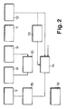
- Fig. 2 ein Blockschaltbild eines im erfindungsgemäßen Ortungssystem eingesetzten Ortungssenders,
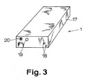
- Fig. 3 eine schematische Darstellung der mechanischen Gestaltung eines Beispiels eines solchen Ortungssenders und
- Fig. 4 ein Blockschaltbild eines im erfindungsgemäßen Ortungssystem eingesetzten Fernschaltsenders.
- 1 is a schematic representation of an embodiment of the location system according to the invention,
- 2 shows a block diagram of a location transmitter used in the location system according to the invention,
- Fig. 3 is a schematic representation of the mechanical design of an example of such a location transmitter and
- Fig. 4 is a block diagram of a remote control transmitter used in the location system according to the invention.
Fig. 1 zeigt den grundsätzlichen Aufbau des erfindungsgemäßen Ortungssystems, das sich insbesondere für den Einsatz im untertägigen Bergbau, beispielsweise zur Ortung und Rettung von verschütteten Bergleuten eignet. Anhand dieses Beispiels soll die Erfindung auch im weiteren Verlauf erläutert werden. Ungeachtet dessen bleibt festzuhalten, daß das erfindungsgemäße Ortungssystem auch an anderer Stelle, beispielsweise bei der Lawinenortung od. dgl. eingesetzt werden kann. Das erfindungsgemäße Ortungssystem kann auch im Rahmen von Personenschutzanlagen eingesetzt werden, beispielsweise um bei Transportbändern für Personen ein automatisches Abschalten an bestimmten Punkten vorzusehen, im Bereich von Arbeitsmaschinen bei Annäherung von Personen eine Sicherungsabschaltung auszulösen usw..1 shows the basic structure of the location system according to the invention, which is particularly suitable for use in underground mining, for example for locating and rescuing buried miners. Using this example, the invention will also be explained in the further course. Regardless of this, it should be noted that the location system according to the invention can also be used elsewhere, for example in avalanche location or the like. The positioning system according to the invention can also be used in the context of personal protection systems, for example to provide automatic shutdown at certain points in conveyor belts for people, to trigger a safety shutdown in the area of work machines when people approach, etc.
Das in Fig. 1 schematisch dargestellte Ortungssystem weist zunächst einen von einer zu ortenden Person zu tragenden Ortungssender 1 und einen von einer suchenden Person od. dgl. zu tragenden oder auch anderweitig angeordneten bzw. transportierten Ortungsempfänger 2 auf. Wie in Fig. 1 angedeutet ist, werden vom Ortungssender 1 ausgesandte elektromagnetische Wellen, ggf. in kodierter Form, vom Ortungsempfänger 2 empfangen und von diesem ortungstechnisch ausgewertet. Das kann mit Hilfe von Analoganzeigen 3, Akustikmeldern 4, Digitalanzeigen 5 und mit verschiedenen weiteren Auswertetechniken erfolgen. Der Ortungssender 1 ist im Bedarfsfalle einschaltbar und, selbstverständlich, zu gegebener Zeit auch wieder ausschaltbar.The locating system shown schematically in FIG. 1 initially has a locating
Kerngedanke der Erfindung ist nun, daß zusätzlich zu dem Ortungssender 1 und dem Ortungsempfänger 2 ein drittes Systemteil vorhanden ist, nämlich ein Fernschaltsender 6. Der Ortungssender 1 ist dabei auch als Empfänger für vom Fernschaltsender 6 ausgesandte elektromagnetische Wellen, gleichfalls wieder mit bestimmter Frequenz bzw. in bestimmter Form kodiert, ausgeführt. Im Ruhezustand steht der Ortungssender 1 in Empfangsfunktion, in der er die vom Fernschaltsender 6 ausgesandten elektromagnetischen Wellen zu empfangen vermag. Erst bei Empfang von vom Fernschaltsender 6 ausgesandten elektromagnetischen Wellen wird der Ortungssender 1 in die Sendefunktion geschaltet. Erst dann also werden vom Ortungssender 1 die zur Ortung erforderlichen elektromagnetischen Wellen ausgesandt, erst dann tritt der mit der Sendefunktion des Ortungssenders 1 verbundene hohe Energieverbrauch auf. Der Ortungssender 1 arbeitet auf diese Weise also immer dann, aber auch nur dann, wenn das ortungstechnisch sinnvoll ist, unabhängig von einer Handhabung durch die zu ortende Person.The main idea of the invention is that, in addition to the locating
Für den Empfang der vom Fernschaltsender 6 ausgesandten elektromagnetischen Wellen bedarf der Ortungssender 1 nur geringer Energie. Folglich empfiehlt es sich, den Ortungssender 1 so zu gestalten, daß er in Empfangsfunktion nur einen minimalen Betriebsstrom von vorzugsweise nur wenigen µA benötigt.The
Wie schon Fig. 1 andeutet, sollte die Reichweite des erfindungsgemäß vorhandenen Fernschaltsenders 6 auf die Reichweite des erfindungsgemäß als Empfänger und Sender ausgestalteten Ortungssenders 1 abgestimmt sein. Die Reichweite hat natürlich auch etwas mit den Umgebungsbedingungen, insbesondere den elektromagnetischen Störeinflüssen von sonstigen Einrichtungen zu tun, so daß sich hier eine gewisse Schwankungsbreite ergibt. Man wird aber beispielsweise auf eine Reichweite des Fernschaltsenders 6 von ≧ 25 m bei abgeschalteten Störeinrichtungen und auf eine Reichweite von ≧ 20 m für den Ortungssender 1 ebenfalls bei abgeschalteten Störeinrichtungen für den Bereich des untertägigen Bergbaus abstellen können.As already indicated in FIG. 1, the range of the remote control transmitter 6 provided according to the invention should be matched to the range of the
Aus Gründen des Energieverbrauchs empfiehlt es sich, daß der Ortungssender 1 nach einer bestimmten, vorgegebenen Zeitspanne nach dem Einschalten der Sendefunktion die Sendefunktion automatisch wieder abschaltet. Die Einschaltzeit der Sendefunktion ist natürlich vom jeweiligen Einsatzzweck abhängig. Für den untertägigen Bergbau haben sich Einschaltzeiten zwischen 3 und 50 min., vorzugsweise zwischen 15 und 30 min., als sinnvoll erwiesen.For reasons of energy consumption, it is recommended that the
Man kann den Ortungssender 1 so betreiben, daß dieser in Sendefunktion auf einer bestimmten Sendefrequenz sendet, jedoch in Empfangsfunktion eine andere Empfangsfrequenz empfängt. Bei entsprechendem Abstand der beiden Frequenzen können auch bei nur einer vorhandenen Sende- und Empfangsantenne beide Funktionen gleichzeitig ablaufen, die Empfangsfunktion also erhalten bleiben, auch wenn die Sendefunktion eingeschaltet ist. Das hat den Vorteil, daß weiter einlaufende Fernschaltsignale den Ortungssender 1 immer wieder neu aktivieren bzw. auch über die eigentliche Abschaltzeit hinaus in der Sendefunktion halten. Schaltungstechnisch einfacher ist es allerdings, tatsächlich eine Umschaltung des Ortungssenders 1 aus der Empfangsfunktion in die Sendefunktion und umgekehrt vorzusehen, also beide Funktionen nicht parallel ablaufen zu lassen.You can operate the locating
Im übrigen empfiehlt es sich, den Ortungssender 1 der Erfindung auch von Hand ausschaltbar, ggf. auch von Hand einschaltbar auszugestalten. Allerdings ist dabei Vorsorge dafür zu treffen, daß kein versehentliches Ein- oder Ausschalten des Ortungssenders 1 erfolgen kann, um die erfindungsgemäß erreichten Vorteile nicht wieder zu gefährden.In addition, it is advisable to configure the
Wesentlich ist, daß der Ortungssender 1 nicht zufällig durch im untertägigen Bergbau vorhandene elektromagnetische Störfelder eingeschaltet werden kann, daß er also weitestgehend störsicher ausgestaltet ist. Dazu empfehlen sich die eingangs erläuterten Kodiermaßnahmen.It is essential that the locating
Das in Fig. 2 dargestellte Blockschaltbild des im erfindungsgemäßen Ortungssystem eingesetzten Ortungssenders 1 zeigt eine Sende- und Empfangsantenne 7, beispielsweise eine Ferritantenne oder eine Dipolantenne, und einen der Sende- und Empfangsantenne 7 nachgeschalteten Selektivverstärker 8 für die vorgesehene Fernschaltfrequenz. Dem Selektivverstärker 8 ist ein Detektor-Transformer 9 nachgeschaltet, wobei beide wiederum über eine automatische Verstärkungsregelung 10 rückgekoppelt sind. Dem Detektor-Transformer 9 ist im dargestellten Ausführungsbeispiel ein Impulsformer 11 nachgeschaltet, dem wiederum ein Impulsfolgedetektor 12 schaltungstechnisch folgt. An den Ausgang des Impulsfolgedetektors 12 ist einerseits ein Zeitgeber 13 zur Vorgabe der Einschaltzeit in Sendefunktion, andererseits ein Zustandsspeicher 14 angeschlossen. Der Zeitgeber 13 ist ausgangsseitig mit dem Zustandsspeicher 14 verbunden. Dem Zustandsspeicher 14 folgt schließlich ein ausgangsseitig an die Sende- und Empfangsantenne 7 angeschlossener Sendeimpulsgenerator 15. Dargestellt ist auch noch die für die eigensichere Spannungsversorgung des Ortungssenders 1 vorgesehene Batterie 16.The block diagram shown in FIG. 2 of the locating
In Empfangsfunktion wird die vom Fernschaltsender 6 ausgesandte Fernschaltfrequenz über die Sende- und Empfangsantenne 7 empfangen. Die empfangenen Signale werden an den Selektivverstärker 8 weitergeleitet, der nur solche mit der vorgesehenen Frequenz verstärkt. Die Verstärkung wird abhängig vom Steuersignal der automatischen Verstärkungsregelung 10 geregelt. Im nachgeschalteten Detektor-Transformer 9 werden die Trägerfrequenz-Signale in Gleichstromimpulse transformiert, und zwar auf einem bestimmten Soll-Signalpegel. Im nachgeschalteten Impulsformer werden die verzerrten Impulse der Impulsfolge aus dem Detektor-Transformer 9 in auswertungstechnisch optimale Rechteckimpulse umgeformt. Der Impulsfolgedetektor 12 erkennt die richtig kodierte Impulsfolge. Läuft die richtige Impulsfolge ein, so wird der Zustandsspeicher 14 in den Aktivzustand geschaltet, was der Einschaltung der Sendefunktion entspricht. Der Zeitgeber 13 schaltet den Zustandsspeicher 14 nach Ablauf der vorgegebenen Einschaltzeit der Sendefunktion wieder zurück, so daß die Sendefunktion abgeschaltet wird. Vom Zustandsspeicher 14 angesteuert wird in der Sendefunktion der Sendeimpulsgenerator 15, der dann über die Sende- und Empfangsantenne 7 die Ortungsfrequenz, die vorzugsweise eine andere ist als die Fernschaltfrequenz, abgibt. Am Zustandsspeicher 14 ist durch einen Pfeil auch die externe, von Hand vorzugebende Möglichkeit zum Rücksetzen des Zustandsspeichers 14, also zum Abschalten der Sendefunktion angedeutet.In the receiving function, the remote switching frequency emitted by the remote control transmitter 6 is received via the transmitting and receiving
Fig. 3 macht den äußeren Aufbau eines Beispiels eines Ortungssenders 1 der in Rede stehenden Art deutlich. Dargestellt ist ein Gehäuse 17, das hinsichtlich Druckfestigkeit und Schlagfestigkeit den Anforderungen entsprechen sollte, die auch an Grubenlampen und Grubenakkumulatoren gestellt werden. Gleichwohl sollte dieses Gehäuse 17 möglichst leichtgewichtig sein, damit der Ortungssender 1 leicht getragen werden kann. An der Stirnseite des Gehäuses 17 erkennt man zwei Ausschaltkontakte 18, die einfach an die Außenseite des Gehäuses 17 geführt sind. Durch elektrisches Kurzschließen der Ausschaltkontakte 18 mit irgendeinem elektrisch leitenden Gegenstand kann der Ortungssender 1 ausgeschaltet, also aus der Sendefunktion herausgeschaltet werden. Dies ist eine sehr einfache Lösung, die sich aber in der Praxis sehr bewährt hat, da eine versehentliche Fehlbedienung äußerst selten ist. Fig. 3 zeigt im übrigen weiter im Gehäuse 17 eine optische Funktionsanzeige 19, hier in Form einer Leuchtdiode. Schließlich zeigt das Gehäuse auch noch zwei Massekontakte 20 der Batterie 16.3 clearly shows the external structure of an example of a
Der in Fig. 1 dargestellte und in Fig. 4 in einem Blockschaltbild näher gezeigte Fernschaltsender 6 sollte gleichfalls als transportables Gerät ausgeführt, insbesondere also von einer suchenden Person, beispielsweise einem Grubenretter, ohne weiteres tragbar sein. Für Ortungszwecke hat der Fernschaltsender 6 dabei zweckmäßigerweise eine große Reichweite und dementsprechend eine hohe Sendeleistung. Im einzelnen nicht dargestellt ist hierbei, daß der Fernschaltsender 6 eine Faltdipolantenne für große Entfernungen, insbesondere Entfernungen von 20 m und mehr, und/oder eine Ferritantenne (dargestellt in Fig. 1) für geringere Entfernungen, insbesondere Entfernungen bis zu 6 m, aufweist.The remote control transmitter 6 shown in FIG. 1 and shown in more detail in a block diagram in FIG. 4 should likewise be designed as a portable device, in particular thus be easily portable by a searching person, for example a mine rescuer. For location purposes, the remote control transmitter 6 expediently has a long range and, accordingly, a high transmission power. Not shown in detail here is that the remote control transmitter 6 has a folding dipole antenna for long distances, in particular distances of 20 m and more, and / or a ferrite antenna (shown in FIG. 1) for shorter distances, in particular distances up to 6 m.
Für die Leistung des Fernschaltsenders 6 für große Reichweiten sind Werte von ca. 10 W sinnvoll.For the power of the remote control transmitter 6 for long ranges, values of approx. 10 W make sense.
Da die Sendeantenne, beispielsweise die Ferritantenne 21 des Fernschaltsenders 6 eine richtungsabhängige Charakteristik hat, empfiehlt es sich, den Fernschaltsender 6 zum Ferneinschalten des Ortungssenders 1 drei Mal nach einander zu aktivieren, wobei jeweils die Hauptebene der Sendekeule der Antenne des Fernschaltsenders 6 um 90° geschwenkt wird. Dann ist man sicher, daß man alle möglichen Empfangsebenen des Ortungssenders 1 getroffen hat.Since the transmitting antenna, for example the
Nicht dargestellt ist in Fig. 1 eine andere Möglichkeit, bei der der Fernschaltsender 6 eine geringe Reichweite, insbesondere eine Reichweite von weniger als 4 m, und dementsprechend eine geringe Sendeleistung aufweist. Ein solches System bietet sich beispielsweise im Rahmen eines Sicherheitssystems für Personen auf einem Personentransportband od. dgl. an. In diesem Fall empfiehlt es sich, daß dem Fernschaltsender 6 ein Alarmempfänger zugeordnet ist. Auch das ist hier nicht dargestellt. Der so mit niedriger Leistung ausgestattete Fernschaltsender 6 und der ggf. vorhandene Alarmempfänger sind dabei stationäre Einrichtungen, die dauerhaft an ausgewählten Stellen, beispielsweise im untertägigen Bergbau, angebracht sind und durch eine sich nähernde Person, die einen entsprechenden Ortungssender 1 trägt, aktiviert werden bzw. den Ortungssender 1 zuvor selbst aktivieren.Another possibility is not shown in FIG. 1, in which the remote control transmitter 6 has a short range, in particular a range of less than 4 m, and accordingly has a low transmission power. Such a system is suitable, for example, as part of a security system for people on a passenger conveyor belt or the like. In this case, it is recommended that the remote control transmitter 6 is assigned an alarm receiver. This is also not shown here. The remote control transmitter 6 thus equipped with low power and the alarm receiver, if any, are stationary devices that are permanently attached to selected locations, for example in underground mining, and are activated or activated by an approaching person who is wearing a
Fig. 4 zeigt in einem Blockschaltbild den schaltungstechnischen Aufbau eines Beispiels eines Fernschaltsenders 6. Der Fernschaltsender 6 weist in diesem Beispiel einen Impulsfolgegenerator 22, einen abstimmbaren Trägerfrequenzoszillator 23, eine Torschaltung 24, einen Ausgangsverstärker 25, eine Antennenabstimmung 26 und die zuvor schon angesprochene Antenne, beispielsweise eine Ferritantenne 21, auf. Weiter dargestellt sind noch ein Spannungsstabilisator 27, eine Batterie als Spannungsversorgung 28 und eine Strommeßschaltung 29 mit der Möglichkeit einer Analogmessung 30 und einer digitalen Leuchtanzeige 31, mit deren Hilfe die optimale Abstimmung der Antenne 21 möglich ist.4 shows in a block diagram the circuitry structure of an example of a remote control transmitter 6. In this example, the remote control transmitter 6 has a
Um den Fernschaltsender 6 auf die Mehrzahl von Ortungssendern 1 mit unterschiedlichen Trägerfrequenzen bzw. Impulsfolgefrequenzen abstimmen zu können, empfiehlt es sich, daß der Trägerfrequenzoszillator 23 durch den gesamten Sendefrequenzbereich wobbelbar ist. Das kann mit unterschiedlichen, auf die Anwendungsfälle abgestimmten Geschwindigkeiten geschehen.In order to be able to tune the remote control transmitter 6 to the plurality of locating
Der Impulsfolgegenerator 22 des in Fig. 4 dargestellten Fernschaltsenders 6 kann beispielsweise im Zyklus 1 : 15 arbeiten, mit einer Impulssequenz im ersten Takt und 15 Pausentakten. Der Trägerfrequenzoszillator 23 erzeugt die Trägerfrequenz. Er kann im Sendefrequenzbereich gewobbelt werden. Die Torschaltung 24 ermöglicht den Durchgang der Trägerfrequenz in dem durch den Impulsfolgegenerator 22 vorgegebenen Bereichen. Die von der Torschaltung 24 abgegebenen Impulse werden im Ausgangsverstärker 25 verstärkt. Mittels der Antennenabstimmung 26 kann die Ausgangsschaltung auf die unterschiedlich einschaltbaren Antennentypen - Faltdipolantenne, Ferritantenne od. dgl. - abgestimmt werden. Die Abstimmsteuerung wird durch die Schaltung 29, 30, 31 ermöglicht. Der Spannungsstabilisator 27 stabilisiert die Speisespannung, um Störeinflüsse von dieser Seite her zu eliminieren.The
Claims (17)
Applications Claiming Priority (2)
| Application Number | Priority Date | Filing Date | Title |
|---|---|---|---|
| DE3917996 | 1989-06-02 | ||
| DE3917996 | 1989-06-02 |
Publications (2)
| Publication Number | Publication Date |
|---|---|
| EP0400489A2 true EP0400489A2 (en) | 1990-12-05 |
| EP0400489A3 EP0400489A3 (en) | 1991-10-23 |
Family
ID=6381914
Family Applications (1)
| Application Number | Title | Priority Date | Filing Date |
|---|---|---|---|
| EP19900109919 Withdrawn EP0400489A3 (en) | 1989-06-02 | 1990-05-25 | Locating system, in particular for underground working |
Country Status (2)
| Country | Link |
|---|---|
| EP (1) | EP0400489A3 (en) |
| CA (1) | CA2018109A1 (en) |
Cited By (3)
| Publication number | Priority date | Publication date | Assignee | Title |
|---|---|---|---|---|
| NL9301542A (en) * | 1993-09-06 | 1995-04-03 | Nedap Nv | Safety device for manually operated electric or electro- mechanical equipment |
| WO2006065219A1 (en) * | 2004-12-13 | 2006-06-22 | Fredrik Carle | A portable rescue device and a method for locating such a device |
| RU2482896C1 (en) * | 2011-12-20 | 2013-05-27 | Открытое акционерное общество "Авангард" | Method of detection of location of buried biological objects or their remains and device for its implementation |
Citations (4)
| Publication number | Priority date | Publication date | Assignee | Title |
|---|---|---|---|---|
| DE3123557A1 (en) * | 1981-06-13 | 1983-03-03 | Bergwerksverband Gmbh, 4300 Essen | Protective belt with marking |
| US4495496A (en) * | 1981-12-15 | 1985-01-22 | Johnson Engineering Corp. | Personnel monitoring and locating system |
| GB2190525A (en) * | 1986-05-15 | 1987-11-18 | Banyaszati Fejlesztesi Intezet | Automatic identification of living creatures and objects |
| EP0271787A2 (en) * | 1986-12-18 | 1988-06-22 | Selectronic Funk- und Sicherheitstechnik GmbH | Personal-protection radio apparatus |
-
1990
- 1990-05-25 EP EP19900109919 patent/EP0400489A3/en not_active Withdrawn
- 1990-06-01 CA CA002018109A patent/CA2018109A1/en not_active Abandoned
Patent Citations (4)
| Publication number | Priority date | Publication date | Assignee | Title |
|---|---|---|---|---|
| DE3123557A1 (en) * | 1981-06-13 | 1983-03-03 | Bergwerksverband Gmbh, 4300 Essen | Protective belt with marking |
| US4495496A (en) * | 1981-12-15 | 1985-01-22 | Johnson Engineering Corp. | Personnel monitoring and locating system |
| GB2190525A (en) * | 1986-05-15 | 1987-11-18 | Banyaszati Fejlesztesi Intezet | Automatic identification of living creatures and objects |
| EP0271787A2 (en) * | 1986-12-18 | 1988-06-22 | Selectronic Funk- und Sicherheitstechnik GmbH | Personal-protection radio apparatus |
Cited By (4)
| Publication number | Priority date | Publication date | Assignee | Title |
|---|---|---|---|---|
| NL9301542A (en) * | 1993-09-06 | 1995-04-03 | Nedap Nv | Safety device for manually operated electric or electro- mechanical equipment |
| WO2006065219A1 (en) * | 2004-12-13 | 2006-06-22 | Fredrik Carle | A portable rescue device and a method for locating such a device |
| US7245899B2 (en) | 2004-12-13 | 2007-07-17 | Fredrik Carle | Portable rescue device and a method for locating such a device |
| RU2482896C1 (en) * | 2011-12-20 | 2013-05-27 | Открытое акционерное общество "Авангард" | Method of detection of location of buried biological objects or their remains and device for its implementation |
Also Published As
| Publication number | Publication date |
|---|---|
| CA2018109A1 (en) | 1990-12-02 |
| EP0400489A3 (en) | 1991-10-23 |
Similar Documents
| Publication | Publication Date | Title |
|---|---|---|
| DE3643236C2 (en) | ||
| DE2802075B2 (en) | Procedures for security and surveillance, in particular for personal security and surveillance, as well as an arrangement for the implementation of the procedure | |
| EP0733916A2 (en) | Portable search apparatus | |
| DE10201505B4 (en) | Safety device for miners | |
| DE3209662A1 (en) | GENERATOR FOR GENERATING RADIO SIGNAL SEQUENCES AND PORTABLE TRANSMITTERS INCLUDING SUCH A GENERATOR | |
| DE2424278B2 (en) | Monitoring system working with electromagnetic radiation | |
| DE4016959A1 (en) | Personnel location system for underground mine | |
| EP0400489A2 (en) | Locating system, in particular for underground working | |
| DE2539438A1 (en) | Beam barrier suitable for component construction - has transmitter emitting electromagnetic radiation and receiver for radiation passing through surveillance space | |
| DE3230556A1 (en) | Light barrier property external security device | |
| DE2436225A1 (en) | Safety alarm system - uses two isolated metal pieces, one as miniature transmitter other as receiver | |
| EP0449173A2 (en) | Arrangement for signalling unauthorized removal of mobile objects | |
| DE2820840C3 (en) | Arrangement for the protection of danger areas in underground operations | |
| DE3442586C2 (en) | ||
| DE2517453C3 (en) | Reporting device | |
| DE10023984A1 (en) | Forgetfulness/loss warning device has portable receiver for receiving signal from transmitter and outputting warning if signal missing or if intensity lower than threshold level | |
| DE19707560A1 (en) | Device for recognizing ready-to-use mobile telephones | |
| DE2425332C2 (en) | Arrangement for safeguarding danger areas in underground operations | |
| DE2452864B2 (en) | OBJECT MONITORING SYSTEM | |
| DE2607226C3 (en) | Switching device for contactless switching of coal plows guided on the face conveyor | |
| DE10219777A1 (en) | Device for operating animal fence or similar has voltage pulse generator connected to voltage source via switching module switched by receiver module receiving code signal from mobile transmitter | |
| DE2625017A1 (en) | Object security monitoring system - uses transponders in objects triggered by interrogation signals | |
| DE2715372A1 (en) | Emergency alarm system for personal security - has belt worn unit with warning bell and short wave signal transmitter | |
| EP0233576A1 (en) | Alarm-system | |
| DE2458434A1 (en) | WIRELESS ALARM SYSTEM |
Legal Events
| Date | Code | Title | Description |
|---|---|---|---|
| PUAI | Public reference made under article 153(3) epc to a published international application that has entered the european phase |
Free format text: ORIGINAL CODE: 0009012 |
|
| AK | Designated contracting states |
Kind code of ref document: A2 Designated state(s): AT CH DE FR GB IT LI SE |
|
| 17P | Request for examination filed |
Effective date: 19901220 |
|
| PUAL | Search report despatched |
Free format text: ORIGINAL CODE: 0009013 |
|
| AK | Designated contracting states |
Kind code of ref document: A3 Designated state(s): AT CH DE FR GB IT LI SE |
|
| 17Q | First examination report despatched |
Effective date: 19940505 |
|
| STAA | Information on the status of an ep patent application or granted ep patent |
Free format text: STATUS: THE APPLICATION IS DEEMED TO BE WITHDRAWN |
|
| 18D | Application deemed to be withdrawn |
Effective date: 19940916 |