EP0403116A2 - Trigger field handling in display apparatus - Google Patents
Trigger field handling in display apparatus Download PDFInfo
- Publication number
- EP0403116A2 EP0403116A2 EP90305955A EP90305955A EP0403116A2 EP 0403116 A2 EP0403116 A2 EP 0403116A2 EP 90305955 A EP90305955 A EP 90305955A EP 90305955 A EP90305955 A EP 90305955A EP 0403116 A2 EP0403116 A2 EP 0403116A2
- Authority
- EP
- European Patent Office
- Prior art keywords
- cursor
- trigger
- display
- user
- trigger field
- Prior art date
- Legal status (The legal status is an assumption and is not a legal conclusion. Google has not performed a legal analysis and makes no representation as to the accuracy of the status listed.)
- Granted
Links
Images

Classifications
-
- G—PHYSICS
- G06—COMPUTING; CALCULATING OR COUNTING
- G06F—ELECTRIC DIGITAL DATA PROCESSING
- G06F3/00—Input arrangements for transferring data to be processed into a form capable of being handled by the computer; Output arrangements for transferring data from processing unit to output unit, e.g. interface arrangements
- G06F3/01—Input arrangements or combined input and output arrangements for interaction between user and computer
- G06F3/048—Interaction techniques based on graphical user interfaces [GUI]
- G06F3/0484—Interaction techniques based on graphical user interfaces [GUI] for the control of specific functions or operations, e.g. selecting or manipulating an object, an image or a displayed text element, setting a parameter value or selecting a range
- G06F3/04842—Selection of displayed objects or displayed text elements
-
- G—PHYSICS
- G06—COMPUTING; CALCULATING OR COUNTING
- G06F—ELECTRIC DIGITAL DATA PROCESSING
- G06F3/00—Input arrangements for transferring data to be processed into a form capable of being handled by the computer; Output arrangements for transferring data from processing unit to output unit, e.g. interface arrangements
- G06F3/01—Input arrangements or combined input and output arrangements for interaction between user and computer
- G06F3/048—Interaction techniques based on graphical user interfaces [GUI]
- G06F3/0481—Interaction techniques based on graphical user interfaces [GUI] based on specific properties of the displayed interaction object or a metaphor-based environment, e.g. interaction with desktop elements like windows or icons, or assisted by a cursor's changing behaviour or appearance
- G06F3/04812—Interaction techniques based on cursor appearance or behaviour, e.g. being affected by the presence of displayed objects
Definitions
- This invention relates to trigger field handling in display apparatus, whereby, for example, in a display driven data processing system, it becomes possible to enable subroutine selection without committing display space to the same.
- an image zone can be selected by a user moving a cursor to the field, under control of a mouse or keyboard keys.
- Such trigger fields may correspond to displayed icons, portions of an image, areas around significant words, etc.
- different program paths can be implemented, subroutines activated, or other processing functions controlled. For example, an icon of of a cat may lead to one story path, while an icon of a dog may lead to a different path.
- the image must have the trigger field identified in advance so that the placement of a cursor therein enables the selection of the particular story path.
- trigger fields are marked on the display so that the user knows where to move the cursor to make the selection.
- the trigger fields are kept relatively small so that the field demarcations do not occupy significant space on the display. This then requires the user to move the cursor, with some precision, to assure that the cursor overlaps the trigger field. Cursor "overshoots” and “undershoots” are common and require time consuming adjustment by the user to assure proper cursor/trigger field alignment.
- trigger fields For optimum user interaction, it is desirable to make trigger fields as large as possible, but then the image becomes cluttered. This results in a larger problem when it is desired to have many trigger fields overlapping various portions of an image. For instance, if an image of an aeroplane is displayed, and it desired to enable the user to select any of the main aircraft subassemblies, e.g. wings, tail, fuselage etc., and then display a blown-up image of the selected portion, the placement of visible trigger fields can significantly clutter the image and may obscure structural features.
- the main aircraft subassemblies e.g. wings, tail, fuselage etc.
- the present invention provides a display-based, user-interface mechanism, supporting a user-controllable cursor facility and trigger means for co-ordinating pre-defined trigger fields with locations of the display, wherein the trigger fields are buried and not displayed, the cursor facility and the trigger means being interactive to scan the trigger field space with the display space and to significantly modify the cursor in display space when a trigger field is encountered in trigger field space.
- This arrangement of invisible or non-displayed "buried" trigger fields can be thought of as providing a real display space and a virtual trigger field space, though physical memory is required for each, and causing the cursor to exist in the same relative position in each space. This enables one to provide a display with trigger fields which facilitate user selection but which do not clutter the image.
- An apparatus which includes memory areas for storing an image and trigger fields for the image, and a display which indicates a cursor in one of two configurations. Circuitry is provided for moving the cursor and enabling it to implement a select operation for a particular subroutine.
- the apparatus employs a technique which enables the trigger fields to be invisible, including displaying the image without trigger fields; and altering the cursor on the display from one configuration to another upon the cursor being moved into an invisible trigger field, to thereby indicate to the user the presence of the trigger field.
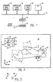
- a block diagram is shown of portions of a data processing system having display capability.
- the processor comprises arithmetic/logic unit 10 coupled to a bus (or buses) 12 to which are also coupled a plurality of memory modules. While the memory modules to be hereinafter described, are shown as independent memories, it is to be understood that they would generally be configured as portions of a larger random access memory rather than as independent modules.
- World plane image memory 14 contains the storage for pixels of a pre-determined size image.
- Viewport image memory 16 contains sufficient pixel storage for a single screen on a display.
- Trigger field memory 18 is a memory area which provides storage for user-defined trigger fields which are overlayed on world plane image memory 14.
- Also connected to bus 12 is a display 20 with a keyboard 22.
- a cursor control input 24 to keyboard 22 may be provided from a mouse or other known cursor control implement.
- keyboard 22 is provided with cursor control direction keys which also enable the movement of the cursor on display 20.
- arithmetic logic unit 10 provides to world plane image memory 14, an image from a scanner or other input device (not shown). A portion of the world plane image in memory 14 is then fed to viewport image memory 16 and then to display 20, for user viewing.
- World plane image memory 14 contains an image which is larger (e.g., 1024 by 1024 pixels) than can be shown on a pixel per pixel basis on display 20.
- viewport image memory 16 is provided with the exact number of pixels which can be displayed in one screen (e.g., 640 by 480 pixels).
- FIG. 2 An exemplary screen to be displayed on display 20 is shown in Fig. 2.
- Screen 30 contains a view of an aeroplane 32 which is in turn, provided with wings, fuselage, landing gear etc.
- a window 34 is shown at the upper left of screen 30 and contains three selectable subroutines.
- the "edit” routine may be selected to alter the showing of one or more portions of aeroplane 32.
- the "display” routine may cause a particular selected portion of the aeroplane to be displayed individually on the screen.
- the "zoom” routine enables a particular feature of the aeroplane to be enlarged for viewing.
- a cursor 36 is movable on screen 30 in either the horizontal or vertical direction.
- a plurality of trigger fields 38, 40, 41, 42 and 44 are shown encompassing various portions of aeroplane 32.
- the placement of cursor 36 within the boundaries of any of the aforementioned trigger fields and a user's subsequent actuation of an appropriate keyboard key, will cause the actuation of a particular subroutine related to the trigger field in accordance with the routine chosen by the user in pull down window 34. For instance, if the user actuates pull down 34, and positions a cursor within any of boxes 50, 52 or 54, the associated subroutine is then enabled to be performed upon a selected portion of aeroplane 32 which is encompassed by the chosen trigger field.
- the subsequent placement of cursor 36 within a selected trigger field, and its selection causes that portion of the aeroplane to be acted upon, as determined by the user selected routine from pull-down 34.
- irregularly shaped trigger fields can be created by overlapping them as shown by trigger fields 40 and 41. In such a case, ascribing the same name to both fields enables the selection of either one to access the subroutines for both.
- cursor 36 be placed within boxes 50, 52 and/or 54 to enable the selection of one or more of the indicated functions.
- trigger fields 38, 40, 42, etc. have been required to be shown on the face of the display to enable the user to know where to position cursor 36 to enable selection of the particular portion of the airframe, upon which the function is to be carried out.
- Cursor 36 is a cross which is movable across the face of screen 30 by a directional cursor control.
- Cursor 36′ is a second configuration of cursor 36 which is automatically displayed when cursor 36 is placed within a trigger field.
- trigger fields 38, 40, 42 and 44 are shown on screen 30.
- the areas encompassing the edit, display and zoom function indications can be employed as trigger fields. For instance, the area beneath line 60 and above line 62 can be used as the trigger field for the zoom function.
- the trigger field "edit” operation commences by ALU 10 causing display 20 to display a world plane image, as well as initialising the position of cursor 36 on screen 30 (box 100).
- the user views screen 30 and the displayed world plane image and decides where trigger fields are to be established.
- To establish a first trigger field the user positions cursor 36 at a corner of a desired trigger field and draws a line to another point to establish a limit of the trigger field (box 102).
- this action is shown on screen 30 by a line, which line may be differentiated from other world plane image lines by either making it a different colour, making it dotted, etc.
- the program recycles to enable other field limits to be inserted decision box 104. If, on the other hand, a user key entry is sensed indicating that the field has been defined, the thus created trigger field is stored to trigger field memory 18 (box 106). A name is then assigned to the stored trigger field and is noted in trigger field memory 18 (box 108). Similarly, the same name is assigned to an associated subroutine which will be enabled when the specific trigger field is selected (box 110). The selection of a trigger field subsequently occurs as the result of a user positioning cursor 36 within its limits and actuating a "select" or "enter” key on keyboard 22.
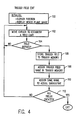
- Fig. 5 the operation of the system, in combination with invisible trigger fields, will be described.
- the user selects a viewport from the world plane image stored in world plane image memory 14.
- the viewport may be all of the world plane image or just a portion thereof (box 120).
- the trigger fields stored within trigger field memory 18 are tested to determine if they fall within the confines of the selected viewport. If so, they are enabled for subsequent interrogation (box 122).
- the system then displays the viewport with no trigger fields indicated (box 124). At the same time a cursor is also displayed and, immediately, a determination is made as to whether the cursor is or is not within a trigger field (box 126). If it is found not to be within a trigger field, a cursor configuration, such as shown at 36 in Fig. 3, is displayed (box 128). If the cursor is found to be within a trigger field, a cursor image, such as is shown in Fig. 3 at 36′, is displayed (box 130). If the first cursor configuration (36) is displayed, the user understands that no trigger field select operation is possible and the user may then continue to move the cursor about the display screen.
- a cursor configuration such as shown at 36 in Fig. 3
- the user may, if desired, select the particular trigger field in which the cursor is positioned (box 132). If the user does not indicate a selection of that trigger field, the position of the cursor is subsequently again tested (box 134) to determine if it still remains within the trigger field. If it is found to be still within the specific trigger field, the program recycles to determine if the user has selected the field. If the cursor is found to have moved out of the trigger field, the cursor display is then changed back to the first configuration (i.e. Fig. 3 - cursor 36) and the program recycles as shown in Fig. 5 (box 136).
- ALU 10 in determining whether the cursor is positioned over a trigger field, notes the position of the cursor and compares it with each of the enabled trigger fields stored within trigger field memory 18. It is the outcome of that comparison which enables the cursor image to either be displayed as cursor 36 or cursor 36′. It can thus be seen that the user is enabled by a simple change of cursor configuration, to identify the presence of invisible trigger fields and to actuate a subroutine associated therewith.
Abstract

Description
- This invention relates to trigger field handling in display apparatus, whereby, for example, in a display driven data processing system, it becomes possible to enable subroutine selection without committing display space to the same.
- It is known that during run-time presentations of display images in a data processing system (e.g. a personal computer), an image zone ("trigger field") can be selected by a user moving a cursor to the field, under control of a mouse or keyboard keys. Such trigger fields may correspond to displayed icons, portions of an image, areas around significant words, etc. Depending upon the user's selection of a trigger field, different program paths can be implemented, subroutines activated, or other processing functions controlled. For example, an icon of of a cat may lead to one story path, while an icon of a dog may lead to a different path. To enable this selectivity, the image must have the trigger field identified in advance so that the placement of a cursor therein enables the selection of the particular story path.
- Characteristically, trigger fields are marked on the display so that the user knows where to move the cursor to make the selection. Of necessity, the trigger fields are kept relatively small so that the field demarcations do not occupy significant space on the display. This then requires the user to move the cursor, with some precision, to assure that the cursor overlaps the trigger field. Cursor "overshoots" and "undershoots" are common and require time consuming adjustment by the user to assure proper cursor/trigger field alignment.
- Thus, for optimum user interaction, it is desirable to make trigger fields as large as possible, but then the image becomes cluttered. This results in a larger problem when it is desired to have many trigger fields overlapping various portions of an image. For instance, if an image of an aeroplane is displayed, and it desired to enable the user to select any of the main aircraft subassemblies, e.g. wings, tail, fuselage etc., and then display a blown-up image of the selected portion, the placement of visible trigger fields can significantly clutter the image and may obscure structural features.
- Accordingly, the present invention provides a display-based, user-interface mechanism, supporting a user-controllable cursor facility and trigger means for co-ordinating pre-defined trigger fields with locations of the display, wherein the trigger fields are buried and not displayed, the cursor facility and the trigger means being interactive to scan the trigger field space with the display space and to significantly modify the cursor in display space when a trigger field is encountered in trigger field space.
- This arrangement of invisible or non-displayed "buried" trigger fields can be thought of as providing a real display space and a virtual trigger field space, though physical memory is required for each, and causing the cursor to exist in the same relative position in each space. This enables one to provide a display with trigger fields which facilitate user selection but which do not clutter the image.
- An apparatus is described hereinafter which includes memory areas for storing an image and trigger fields for the image, and a display which indicates a cursor in one of two configurations. Circuitry is provided for moving the cursor and enabling it to implement a select operation for a particular subroutine. The apparatus employs a technique which enables the trigger fields to be invisible, including displaying the image without trigger fields; and altering the cursor on the display from one configuration to another upon the cursor being moved into an invisible trigger field, to thereby indicate to the user the presence of the trigger field.
- The present invention will be described further by way of example with reference to an embodiment thereof as illustrated in the accompanying drawings, in which
- Fig. 1 is a high level block diagram of a display processor adapted to handle buried trigger fields;
- Fig. 2 is an example of a display screen showing the placement of images and trigger fields;
- Fig. 3 is an illustration of two cursor configurations that can be used;
- Fig. 4 is a high level flow diagram illustrating the process for creating an invisible trigger field on a display image; and
- Fig. 5 is a high level flow diagram illustrating the operation of the display processor.
- Referring now to Fig. 1, a block diagram is shown of portions of a data processing system having display capability. As is known, the processor comprises arithmetic/
logic unit 10 coupled to a bus (or buses) 12 to which are also coupled a plurality of memory modules. While the memory modules to be hereinafter described, are shown as independent memories, it is to be understood that they would generally be configured as portions of a larger random access memory rather than as independent modules. - World plane image memory 14 contains the storage for pixels of a pre-determined size image.
Viewport image memory 16 contains sufficient pixel storage for a single screen on a display.Trigger field memory 18 is a memory area which provides storage for user-defined trigger fields which are overlayed on world plane image memory 14. Also connected tobus 12 is adisplay 20 with akeyboard 22. Acursor control input 24 tokeyboard 22 may be provided from a mouse or other known cursor control implement. In addition,keyboard 22 is provided with cursor control direction keys which also enable the movement of the cursor ondisplay 20. - The operation of the system shown in Fig. 1 is conventional in that
arithmetic logic unit 10 provides to world plane image memory 14, an image from a scanner or other input device (not shown). A portion of the world plane image in memory 14 is then fed to viewportimage memory 16 and then to display 20, for user viewing. World plane image memory 14 contains an image which is larger (e.g., 1024 by 1024 pixels) than can be shown on a pixel per pixel basis ondisplay 20. Thus,viewport image memory 16 is provided with the exact number of pixels which can be displayed in one screen (e.g., 640 by 480 pixels). - An exemplary screen to be displayed on
display 20 is shown in Fig. 2.Screen 30 contains a view of anaeroplane 32 which is in turn, provided with wings, fuselage, landing gear etc. Awindow 34 is shown at the upper left ofscreen 30 and contains three selectable subroutines. The "edit" routine may be selected to alter the showing of one or more portions ofaeroplane 32. The "display" routine may cause a particular selected portion of the aeroplane to be displayed individually on the screen. The "zoom" routine enables a particular feature of the aeroplane to be enlarged for viewing. - A
cursor 36 is movable onscreen 30 in either the horizontal or vertical direction. A plurality oftrigger fields aeroplane 32. The placement ofcursor 36 within the boundaries of any of the aforementioned trigger fields and a user's subsequent actuation of an appropriate keyboard key, will cause the actuation of a particular subroutine related to the trigger field in accordance with the routine chosen by the user in pull downwindow 34. For instance, if the user actuates pull down 34, and positions a cursor within any ofboxes aeroplane 32 which is encompassed by the chosen trigger field. The subsequent placement ofcursor 36 within a selected trigger field, and its selection, causes that portion of the aeroplane to be acted upon, as determined by the user selected routine from pull-down 34. - It should be noted that irregularly shaped trigger fields can be created by overlapping them as shown by
trigger fields - Prior art systems have required that
cursor 36 be placed withinboxes trigger fields cursor 36 to enable selection of the particular portion of the airframe, upon which the function is to be carried out. - Referring now to Fig. 3, two forms of
cursor 36 are shown.Cursor 36 is a cross which is movable across the face ofscreen 30 by a directional cursor control.Cursor 36′ is a second configuration ofcursor 36 which is automatically displayed whencursor 36 is placed within a trigger field. As will be hereinafter understood, during the operation, none oftrigger fields screen 30. In addition, in lieu of employingtrigger boxes line 60 and aboveline 62 can be used as the trigger field for the zoom function. - Referring to Fig. 4, the manner in which the various trigger fields are inserted is now described. The trigger field "edit" operation commences by
ALU 10 causingdisplay 20 to display a world plane image, as well as initialising the position ofcursor 36 on screen 30 (box 100). The user then viewsscreen 30 and the displayed world plane image and decides where trigger fields are to be established. To establish a first trigger field, theuser positions cursor 36 at a corner of a desired trigger field and draws a line to another point to establish a limit of the trigger field (box 102). As is known, this action is shown onscreen 30 by a line, which line may be differentiated from other world plane image lines by either making it a different colour, making it dotted, etc. - If at the termination of the creation of a field limit, there is no user key entry that a full trigger field has been established, then the program recycles to enable other field limits to be inserted
decision box 104. If, on the other hand, a user key entry is sensed indicating that the field has been defined, the thus created trigger field is stored to trigger field memory 18 (box 106). A name is then assigned to the stored trigger field and is noted in trigger field memory 18 (box 108). Similarly, the same name is assigned to an associated subroutine which will be enabled when the specific trigger field is selected (box 110). The selection of a trigger field subsequently occurs as the result of auser positioning cursor 36 within its limits and actuating a "select" or "enter" key onkeyboard 22. - Once all trigger fields have been created (decision box 112); the routine exits with all of the field limits stored in
trigger field memory 18. If more fields remain to be created, the program recycles to enable their creation. The displayed world plane image with trigger fields overlayed is then returned to a separate storage area for later viewing, if desired. The original world plane image still remains in world plane image memory 14 without the trigger fields indicated thereon. - Turning now to Fig. 5, the operation of the system, in combination with invisible trigger fields, will be described. Initially, the user selects a viewport from the world plane image stored in world plane image memory 14. The viewport may be all of the world plane image or just a portion thereof (box 120). Depending upon the selected viewport, the trigger fields stored within
trigger field memory 18 are tested to determine if they fall within the confines of the selected viewport. If so, they are enabled for subsequent interrogation (box 122). - The system then displays the viewport with no trigger fields indicated (box 124). At the same time a cursor is also displayed and, immediately, a determination is made as to whether the cursor is or is not within a trigger field (box 126). If it is found not to be within a trigger field, a cursor configuration, such as shown at 36 in Fig. 3, is displayed (box 128). If the cursor is found to be within a trigger field, a cursor image, such as is shown in Fig. 3 at 36′, is displayed (box 130). If the first cursor configuration (36) is displayed, the user understands that no trigger field select operation is possible and the user may then continue to move the cursor about the display screen. If the second cursor configuration (36′) is evidenced on the screen, the user may, if desired, select the particular trigger field in which the cursor is positioned (box 132). If the user does not indicate a selection of that trigger field, the position of the cursor is subsequently again tested (box 134) to determine if it still remains within the trigger field. If it is found to be still within the specific trigger field, the program recycles to determine if the user has selected the field. If the cursor is found to have moved out of the trigger field, the cursor display is then changed back to the first configuration (i.e. Fig. 3 - cursor 36) and the program recycles as shown in Fig. 5 (box 136).
- If the user actuates a select key (box 132) while the second cursor configuration is showing, the name of the trigger field in which the cursor is positioned is accessed (box 138), and the subroutine with the identical name is also accessed and brought into action (
boxes 140, 142). -
ALU 10, in determining whether the cursor is positioned over a trigger field, notes the position of the cursor and compares it with each of the enabled trigger fields stored withintrigger field memory 18. It is the outcome of that comparison which enables the cursor image to either be displayed ascursor 36 orcursor 36′. It can thus be seen that the user is enabled by a simple change of cursor configuration, to identify the presence of invisible trigger fields and to actuate a subroutine associated therewith.
Claims (6)
Applications Claiming Priority (2)
| Application Number | Priority Date | Filing Date | Title |
|---|---|---|---|
| US36740689A | 1989-06-16 | 1989-06-16 | |
| US367406 | 1989-06-16 |
Publications (3)
| Publication Number | Publication Date |
|---|---|
| EP0403116A2 true EP0403116A2 (en) | 1990-12-19 |
| EP0403116A3 EP0403116A3 (en) | 1991-04-24 |
| EP0403116B1 EP0403116B1 (en) | 1995-12-13 |
Family
ID=23447043
Family Applications (1)
| Application Number | Title | Priority Date | Filing Date |
|---|---|---|---|
| EP90305955A Expired - Lifetime EP0403116B1 (en) | 1989-06-16 | 1990-05-31 | Trigger field handling in display apparatus |
Country Status (8)
| Country | Link |
|---|---|
| US (1) | US5307457A (en) |
| EP (1) | EP0403116B1 (en) |
| JP (1) | JPH0325575A (en) |
| BR (1) | BR9002740A (en) |
| CA (1) | CA2012796C (en) |
| DE (1) | DE69024107T2 (en) |
| ES (1) | ES2080799T3 (en) |
| PE (1) | PE16191A1 (en) |
Cited By (4)
| Publication number | Priority date | Publication date | Assignee | Title |
|---|---|---|---|---|
| EP0529529A2 (en) * | 1991-08-23 | 1993-03-03 | Fujitsu Limited | A graphic data processing system |
| EP0575185A2 (en) * | 1992-06-19 | 1993-12-22 | Sony Corporation | Image display apparatus |
| WO1998026346A1 (en) * | 1996-12-13 | 1998-06-18 | Twosuns Media Development Gmbh | Computer control system |
| WO2007072195A1 (en) * | 2005-12-22 | 2007-06-28 | Nokia Corporation | Method and device for controlling a menu on a mobile communications device |
Families Citing this family (24)
| Publication number | Priority date | Publication date | Assignee | Title |
|---|---|---|---|---|
| JPH03282676A (en) * | 1990-03-30 | 1991-12-12 | Hitachi Ltd | Information retrieving method |
| FR2683648B1 (en) * | 1991-11-12 | 1996-12-13 | Apple Computer | METHOD FOR CHOOSING OBJECTS IN A MOVING IMAGE SEQUENCE AND CORRESPONDING SUCCESS TEST TRACK |
| US5729704A (en) * | 1993-07-21 | 1998-03-17 | Xerox Corporation | User-directed method for operating on an object-based model data structure through a second contextual image |
| US5652851A (en) * | 1993-07-21 | 1997-07-29 | Xerox Corporation | User interface technique for producing a second image in the spatial context of a first image using a model-based operation |
| US5912666A (en) * | 1994-08-23 | 1999-06-15 | Object Technology Licensing Corp. | Object-oriented global cursor tool |
| US5727141A (en) * | 1995-05-05 | 1998-03-10 | Apple Computer, Inc. | Method and apparatus for identifying user-selectable regions within multiple display frames |
| US5737553A (en) * | 1995-07-14 | 1998-04-07 | Novell, Inc. | Colormap system for mapping pixel position and color index to executable functions |
| JP2999947B2 (en) * | 1995-07-28 | 2000-01-17 | インターナショナル・ビジネス・マシーンズ・コーポレイション | Method and apparatus for operating an object displayed on a display screen |
| US5805165A (en) * | 1995-08-31 | 1998-09-08 | Microsoft Corporation | Method of selecting a displayed control item |
| AU4430797A (en) * | 1996-09-27 | 1998-04-17 | Sabre Group, Inc., The | Photo enhanced help desk system |
| US5917486A (en) * | 1996-11-04 | 1999-06-29 | Prolexia Reading Education Software Corporation | System and method for client program control of a computer display cursor |
| US5874959A (en) * | 1997-06-23 | 1999-02-23 | Rowe; A. Allen | Transparent overlay viewer interface |
| US6075537A (en) * | 1997-11-20 | 2000-06-13 | International Business Machines Corporation | Ease of use interface to hotspots in hypertext document pages in network display stations |
| US20010030660A1 (en) * | 1999-12-10 | 2001-10-18 | Roustem Zainoulline | Interactive graphical user interface and method for previewing media products |
| US7747673B1 (en) * | 2000-09-08 | 2010-06-29 | Corel Corporation | Method and apparatus for communicating during automated data processing |
| US7296238B1 (en) * | 2000-09-08 | 2007-11-13 | Corel Corporation | Method and apparatus for triggering automated processing of data |
| US7853833B1 (en) | 2000-09-08 | 2010-12-14 | Corel Corporation | Method and apparatus for enhancing reliability of automated data processing |
| US20050075166A1 (en) * | 2002-05-14 | 2005-04-07 | Hemstreet Paul A. | Media program with interactive feature |
| GB0229772D0 (en) * | 2002-12-23 | 2003-01-29 | Univ Nottingham | Optically triggered interactive apparatus and method of triggering said apparatus |
| US7456993B2 (en) * | 2003-03-28 | 2008-11-25 | Vistaprint Technologies Limited | Electronic document location indication and navigation method, system and program |
| EP1738246A4 (en) * | 2004-03-09 | 2011-02-09 | Freedom Scientific Inc | Low vision enhancement for graphic user interface |
| WO2006045879A1 (en) * | 2004-10-28 | 2006-05-04 | Nokia Corporation | Device menu |
| US8739052B2 (en) * | 2005-07-27 | 2014-05-27 | Microsoft Corporation | Media user interface layers and overlays |
| US9298337B2 (en) | 2013-02-07 | 2016-03-29 | Google Inc. | Mechanism to reduce accidental clicks on online content |
Citations (3)
| Publication number | Priority date | Publication date | Assignee | Title |
|---|---|---|---|---|
| US4354184A (en) * | 1979-09-28 | 1982-10-12 | Siemens Aktiengesellschaft | Display system for localizing regions in a mixed text & picture display |
| GB2181627A (en) * | 1985-09-10 | 1987-04-23 | Interactive Tech Limited | Information processing system |
| US4731609A (en) * | 1986-11-03 | 1988-03-15 | International Business Machines Corporation | Fast correlation of markers with graphic entities |
Family Cites Families (6)
| Publication number | Priority date | Publication date | Assignee | Title |
|---|---|---|---|---|
| US4686522A (en) * | 1985-02-19 | 1987-08-11 | International Business Machines Corporation | Method of editing graphic objects in an interactive draw graphic system using implicit editing actions |
| GB2172177A (en) * | 1985-03-06 | 1986-09-10 | Philips Electronic Associated | Electronic information display systems |
| US4698625A (en) * | 1985-05-30 | 1987-10-06 | International Business Machines Corp. | Graphic highlight adjacent a pointing cursor |
| US4757549A (en) * | 1985-12-12 | 1988-07-12 | International Business Machines Corp. | Freehand drawing containing invisible lines |
| US4899136A (en) * | 1986-04-28 | 1990-02-06 | Xerox Corporation | Data processor having a user interface display with metaphoric objects |
| US4772882A (en) * | 1986-07-18 | 1988-09-20 | Commodore-Amiga, Inc. | Cursor controller user interface system |
-
1990
- 1990-03-22 CA CA002012796A patent/CA2012796C/en not_active Expired - Fee Related
- 1990-05-15 JP JP2125245A patent/JPH0325575A/en active Pending
- 1990-05-31 DE DE69024107T patent/DE69024107T2/en not_active Expired - Lifetime
- 1990-05-31 EP EP90305955A patent/EP0403116B1/en not_active Expired - Lifetime
- 1990-05-31 ES ES90305955T patent/ES2080799T3/en not_active Expired - Lifetime
- 1990-06-11 BR BR909002740A patent/BR9002740A/en unknown
- 1990-06-12 PE PE1990170686A patent/PE16191A1/en unknown
-
1993
- 1993-01-25 US US08/008,259 patent/US5307457A/en not_active Expired - Lifetime
Patent Citations (3)
| Publication number | Priority date | Publication date | Assignee | Title |
|---|---|---|---|---|
| US4354184A (en) * | 1979-09-28 | 1982-10-12 | Siemens Aktiengesellschaft | Display system for localizing regions in a mixed text & picture display |
| GB2181627A (en) * | 1985-09-10 | 1987-04-23 | Interactive Tech Limited | Information processing system |
| US4731609A (en) * | 1986-11-03 | 1988-03-15 | International Business Machines Corporation | Fast correlation of markers with graphic entities |
Cited By (10)
| Publication number | Priority date | Publication date | Assignee | Title |
|---|---|---|---|---|
| EP0529529A2 (en) * | 1991-08-23 | 1993-03-03 | Fujitsu Limited | A graphic data processing system |
| EP0529529A3 (en) * | 1991-08-23 | 1993-04-14 | Fujitsu Limited | A graphic data processing system |
| US5432894A (en) * | 1991-08-23 | 1995-07-11 | Fujitsu Limited | Graphic data processing system with improved retrieval and display of graphical forms |
| EP0575185A2 (en) * | 1992-06-19 | 1993-12-22 | Sony Corporation | Image display apparatus |
| EP0575185A3 (en) * | 1992-06-19 | 1994-08-31 | Sony Corp | |
| US5452012A (en) * | 1992-06-19 | 1995-09-19 | Sony Corporation | Image display apparatus |
| WO1998026346A1 (en) * | 1996-12-13 | 1998-06-18 | Twosuns Media Development Gmbh | Computer control system |
| WO2007072195A1 (en) * | 2005-12-22 | 2007-06-28 | Nokia Corporation | Method and device for controlling a menu on a mobile communications device |
| EP2713588A1 (en) * | 2005-12-22 | 2014-04-02 | Core Wireless Licensing S.a.r.l. | Method and device for controlling a menu on a mobile communications device |
| US9086779B2 (en) | 2005-12-22 | 2015-07-21 | Core Wireless Licensing S.A.R.L. | Input device |
Also Published As
| Publication number | Publication date |
|---|---|
| US5307457A (en) | 1994-04-26 |
| JPH0325575A (en) | 1991-02-04 |
| DE69024107T2 (en) | 1996-06-20 |
| EP0403116B1 (en) | 1995-12-13 |
| ES2080799T3 (en) | 1996-02-16 |
| BR9002740A (en) | 1991-08-20 |
| CA2012796C (en) | 1996-05-14 |
| CA2012796A1 (en) | 1990-12-16 |
| EP0403116A3 (en) | 1991-04-24 |
| DE69024107D1 (en) | 1996-01-25 |
| PE16191A1 (en) | 1991-05-27 |
Similar Documents
| Publication | Publication Date | Title |
|---|---|---|
| EP0403116A2 (en) | Trigger field handling in display apparatus | |
| US5396590A (en) | Non-modal method and apparatus for manipulating graphical objects | |
| EP0703563A2 (en) | Method and apparatus for displaying overlapping graphical objects on a computer monitor | |
| DE4406668C2 (en) | Method and device for operating a touch-sensitive display device | |
| EP0763714B1 (en) | Cursor controlled navigation system for aircraft | |
| US5528260A (en) | Method and apparatus for proportional auto-scrolling | |
| US5956032A (en) | Signalling a user attempt to resize a window beyond its limit | |
| EP0176950A2 (en) | Screen manager for data processing system | |
| US6124861A (en) | Method and apparatus for unambiguous selection of graphic objects, keypoints and relationships | |
| EP0657800A1 (en) | Method and system for display manipulation of multiple applications in a data processing system | |
| AU664538B2 (en) | Software for executing plural independent application programs | |
| JP2000089929A (en) | Method and device for data processing and computer- readable recording medium | |
| GB2310989A (en) | Graphical user interface | |
| US4354185A (en) | Display system for localizing regions in a mixed text and picture display | |
| US5671380A (en) | Method and apparatus for creating a graphic using graphic icons | |
| US5202671A (en) | Pick function implementation in a parallel processing system | |
| EP0653697A2 (en) | Cursor with multiple pointing spots | |
| US5602453A (en) | Coordinate system display guide for a numerical control apparatus | |
| EP0355166B1 (en) | Picture element correction method | |
| EP0100798A1 (en) | Computer aided design system | |
| US20020118227A1 (en) | Graphical user interface | |
| EP0281054B1 (en) | Method and apparatus for displaying a pointer | |
| US11205403B2 (en) | Drawing order determining method, drawing method, and drawing apparatus | |
| JP2536634B2 (en) | Identification display method of selection target | |
| CA2021665C (en) | Pick function implementation in a parallel processing system |
Legal Events
| Date | Code | Title | Description |
|---|---|---|---|
| PUAI | Public reference made under article 153(3) epc to a published international application that has entered the european phase |
Free format text: ORIGINAL CODE: 0009012 |
|
| AK | Designated contracting states |
Kind code of ref document: A2 Designated state(s): BE CH DE ES FR GB IT LI NL SE |
|
| 17P | Request for examination filed |
Effective date: 19901213 |
|
| PUAL | Search report despatched |
Free format text: ORIGINAL CODE: 0009013 |
|
| PUAF | Information related to the publication of a search report (a3 document) modified or deleted |
Free format text: ORIGINAL CODE: 0009199SEPU |
|
| AK | Designated contracting states |
Kind code of ref document: A3 Designated state(s): BE CH DE ES FR GB IT LI NL SE |
|
| D17D | Deferred search report published (deleted) | ||
| PUAL | Search report despatched |
Free format text: ORIGINAL CODE: 0009013 |
|
| AK | Designated contracting states |
Kind code of ref document: A3 Designated state(s): BE CH DE ES FR GB IT LI NL SE |
|
| 17Q | First examination report despatched |
Effective date: 19940127 |
|
| GRAA | (expected) grant |
Free format text: ORIGINAL CODE: 0009210 |
|
| AK | Designated contracting states |
Kind code of ref document: B1 Designated state(s): BE CH DE ES FR GB IT LI NL SE |
|
| REF | Corresponds to: |
Ref document number: 69024107 Country of ref document: DE Date of ref document: 19960125 |
|
| ITF | It: translation for a ep patent filed |
Owner name: IBM - DR. ALFREDO BRAVI |
|
| REG | Reference to a national code |
Ref country code: CH Ref legal event code: NV Representative=s name: CARL O. BARTH C/O IBM CORPORATION ZURICH INTELLECT |
|
| REG | Reference to a national code |
Ref country code: ES Ref legal event code: FG2A Ref document number: 2080799 Country of ref document: ES Kind code of ref document: T3 |
|
| ET | Fr: translation filed | ||
| PLBE | No opposition filed within time limit |
Free format text: ORIGINAL CODE: 0009261 |
|
| STAA | Information on the status of an ep patent application or granted ep patent |
Free format text: STATUS: NO OPPOSITION FILED WITHIN TIME LIMIT |
|
| 26N | No opposition filed | ||
| REG | Reference to a national code |
Ref country code: GB Ref legal event code: IF02 |
|
| PGFP | Annual fee paid to national office [announced via postgrant information from national office to epo] |
Ref country code: ES Payment date: 20030520 Year of fee payment: 14 |
|
| PGFP | Annual fee paid to national office [announced via postgrant information from national office to epo] |
Ref country code: NL Payment date: 20030530 Year of fee payment: 14 |
|
| PGFP | Annual fee paid to national office [announced via postgrant information from national office to epo] |
Ref country code: BE Payment date: 20030619 Year of fee payment: 14 |
|
| PG25 | Lapsed in a contracting state [announced via postgrant information from national office to epo] |
Ref country code: BE Free format text: LAPSE BECAUSE OF NON-PAYMENT OF DUE FEES Effective date: 20040531 |
|
| PG25 | Lapsed in a contracting state [announced via postgrant information from national office to epo] |
Ref country code: ES Free format text: LAPSE BECAUSE OF NON-PAYMENT OF DUE FEES Effective date: 20040601 |
|
| BERE | Be: lapsed |
Owner name: *INTERNATIONAL BUSINESS MACHINES CORP. Effective date: 20040531 |
|
| PG25 | Lapsed in a contracting state [announced via postgrant information from national office to epo] |
Ref country code: NL Free format text: LAPSE BECAUSE OF NON-PAYMENT OF DUE FEES Effective date: 20041201 |
|
| NLV4 | Nl: lapsed or anulled due to non-payment of the annual fee |
Effective date: 20041201 |
|
| REG | Reference to a national code |
Ref country code: ES Ref legal event code: FD2A Effective date: 20040601 |
|
| PGFP | Annual fee paid to national office [announced via postgrant information from national office to epo] |
Ref country code: SE Payment date: 20090525 Year of fee payment: 20 Ref country code: IT Payment date: 20090513 Year of fee payment: 20 Ref country code: DE Payment date: 20090528 Year of fee payment: 20 Ref country code: FR Payment date: 20090505 Year of fee payment: 20 |
|
| PGFP | Annual fee paid to national office [announced via postgrant information from national office to epo] |
Ref country code: CH Payment date: 20090827 Year of fee payment: 20 Ref country code: GB Payment date: 20090519 Year of fee payment: 20 |
|
| REG | Reference to a national code |
Ref country code: CH Ref legal event code: PL |
|
| EUG | Se: european patent has lapsed | ||
| PG25 | Lapsed in a contracting state [announced via postgrant information from national office to epo] |
Ref country code: GB Free format text: LAPSE BECAUSE OF EXPIRATION OF PROTECTION Effective date: 20100530 |
|
| PG25 | Lapsed in a contracting state [announced via postgrant information from national office to epo] |
Ref country code: DE Free format text: LAPSE BECAUSE OF EXPIRATION OF PROTECTION Effective date: 20100531 |