EP0404166A2 - Hinge device having mechanism for stopping movable member at open position - Google Patents
Hinge device having mechanism for stopping movable member at open position Download PDFInfo
- Publication number
- EP0404166A2 EP0404166A2 EP19900111798 EP90111798A EP0404166A2 EP 0404166 A2 EP0404166 A2 EP 0404166A2 EP 19900111798 EP19900111798 EP 19900111798 EP 90111798 A EP90111798 A EP 90111798A EP 0404166 A2 EP0404166 A2 EP 0404166A2
- Authority
- EP
- European Patent Office
- Prior art keywords
- shaft
- hinge device
- terized
- charac
- case
- Prior art date
- Legal status (The legal status is an assumption and is not a legal conclusion. Google has not performed a legal analysis and makes no representation as to the accuracy of the status listed.)
- Granted
Links
Images


Classifications
-
- G—PHYSICS
- G06—COMPUTING; CALCULATING OR COUNTING
- G06F—ELECTRIC DIGITAL DATA PROCESSING
- G06F1/00—Details not covered by groups G06F3/00 - G06F13/00 and G06F21/00
- G06F1/16—Constructional details or arrangements
- G06F1/1613—Constructional details or arrangements for portable computers
- G06F1/1615—Constructional details or arrangements for portable computers with several enclosures having relative motions, each enclosure supporting at least one I/O or computing function
- G06F1/1616—Constructional details or arrangements for portable computers with several enclosures having relative motions, each enclosure supporting at least one I/O or computing function with folding flat displays, e.g. laptop computers or notebooks having a clamshell configuration, with body parts pivoting to an open position around an axis parallel to the plane they define in closed position
-
- E—FIXED CONSTRUCTIONS
- E05—LOCKS; KEYS; WINDOW OR DOOR FITTINGS; SAFES
- E05D—HINGES OR SUSPENSION DEVICES FOR DOORS, WINDOWS OR WINGS
- E05D7/00—Hinges or pivots of special construction
-
- G—PHYSICS
- G06—COMPUTING; CALCULATING OR COUNTING
- G06F—ELECTRIC DIGITAL DATA PROCESSING
- G06F1/00—Details not covered by groups G06F3/00 - G06F13/00 and G06F21/00
- G06F1/16—Constructional details or arrangements
- G06F1/1613—Constructional details or arrangements for portable computers
- G06F1/1633—Constructional details or arrangements of portable computers not specific to the type of enclosures covered by groups G06F1/1615 - G06F1/1626
- G06F1/1675—Miscellaneous details related to the relative movement between the different enclosures or enclosure parts
- G06F1/1681—Details related solely to hinges
-
- G—PHYSICS
- G06—COMPUTING; CALCULATING OR COUNTING
- G06F—ELECTRIC DIGITAL DATA PROCESSING
- G06F1/00—Details not covered by groups G06F3/00 - G06F13/00 and G06F21/00
- G06F1/16—Constructional details or arrangements
- G06F1/1613—Constructional details or arrangements for portable computers
- G06F1/1633—Constructional details or arrangements of portable computers not specific to the type of enclosures covered by groups G06F1/1615 - G06F1/1626
- G06F1/1675—Miscellaneous details related to the relative movement between the different enclosures or enclosure parts
- G06F1/1683—Miscellaneous details related to the relative movement between the different enclosures or enclosure parts for the transmission of signal or power between the different housings, e.g. details of wired or wireless communication, passage of cabling
-
- F—MECHANICAL ENGINEERING; LIGHTING; HEATING; WEAPONS; BLASTING
- F16—ENGINEERING ELEMENTS AND UNITS; GENERAL MEASURES FOR PRODUCING AND MAINTAINING EFFECTIVE FUNCTIONING OF MACHINES OR INSTALLATIONS; THERMAL INSULATION IN GENERAL
- F16C—SHAFTS; FLEXIBLE SHAFTS; ELEMENTS OR CRANKSHAFT MECHANISMS; ROTARY BODIES OTHER THAN GEARING ELEMENTS; BEARINGS
- F16C11/00—Pivots; Pivotal connections
- F16C11/04—Pivotal connections
- F16C11/10—Arrangements for locking
Definitions
- the present invention relates to a hinge device for use in a portable apparatus such as a lap-top or portable personal computer and more particularly to a hinge device having a mechanism for stopping a movable member of the apparatus at an open position, by virtue of the frictional force exerted by a spring member.
- U.S. Patent 4,571,456 discloses a portable personal computer which comprises a rectangular case, a keyboard attached to the case, and a display unit hinged to the case by a hinge.
- the display unit Connected by the hinge to the case, the display unit can rotate between a position (hereinafter referred to as “closed position") where it covers the keyboard and a position (hereinafter referred to as “opened position”) where it stands upright at the rear of the keyboard.
- the hinge includes a mechanism which experts a frictional force to stop the display unit at any position between the closed position and the open position.
- a hinge having such a mechanism and designed to connect a display unit to the case of a personal computer is disclosed in Published Unexamined Japanese Patent Application No. 59-99111.
- This hinge comprises a shaft and a coil spring wound around the shaft.
- the shaft is fastened at one end to the display unit and at the other end to the case.
- the coil spring is wound more and more tightly around the shaft, whereby a frictional force is generated between the shaft and the coil spring.
- the display unit is held up at a position where the user takes his or her hand off the display unit, provided that the hinge shaft and the coil spring have a proper outside diameter and an appropriate inside diameter, respectively, and are set at correct positions. It requires much time and labor to make the shaft and the spring with sufficient precision and to set them in a correct positional relationship. Consequently, the manufacturing cost of the hinge is inevitably high.
- the object of the present invention is to provide a hinge device whose components need not be machined or positioned with high-precision, and which is therefore easy to manufacture and can, thus, be manufactured at low cost.
- a hinge device comprising: a shaft to be connected at one end to a first member; support means mounted on the shaft, for supporting a second member such that the second member rotates around the shaft; and ring-shaped spring means held and compressed between the shaft and the support means, for generating a friction between said shaft and said support means when the first and second members are rotated relative to each other around the shaft, thereby to suppress the rotation of the first and second members.
- the ring-shaped spring means can easily be incorporated in the hinge device, when pushed into the gap between the shaft and the support means. Once so incorporated, the ring-shaped spring means can exert a frictional force between the shaft and the support means. Unlike the coil spring used in the conventional hinge described above, the spring means need not be machined or positioned with high precision.
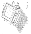
- Fig. 1 illustrates a lap-top or portable personal computer 1.
- the computer 1 has a case 2 made of a synthetic resin and is shaped like a thin rectangular box comprising a bottom case 3 which is covered by a top cover 4.
- a keyboard 5 is attached to the front half of the top cover 4.
- the rearmost part of the half of the top cover 4 is thicker than the front most part of the rear half.
- Two recesses 6a and 6b are formed in the front-left and -right portions of the rear half of the top cover 4, respectively.
- a printed circuit board 7, on which are mounted a number of circuit parts (not shown), is incorporated in the case 2.
- the computer 1 further comprises a flat-panel type display unit 8 located at the rear of the keyboard 5.
- the display unit 8 comprises a rectangular housing 9 and a flat liquid-crystal display 11 located within the housing 9.
- the housing 9 is composed of a base panel 10a and a front panel 10b, both shaped like a rectangular plate. These panels 10a and 10b are fastened together, by means of screws (not shown) at their four corners.
- the liquid-crystal display 11, which has a screen 12, is inter posed between the panels 10a and 10b.
- the screen 12 is exposed through the rectangular opening 13 made in the front panel 10b.
- the display unit 8 is attached to the case 2 such that it rotate between a position (hereinafter referred to as “closed position") where it covers the keyboard 6 and a position (herein after referred to as “opened position") where it stands upright at the rear of the keyboard 5.
- the display unit 8 covers the entire keyboard 5 when it is rotated to the closed position.
- the unit 8 remains in the closed position, its top is at the same level as the upper surface of the top cover 4, and its left and right sides are level with those of the top cover 4. In this condition, the case 2 and the display unit 8 form a relatively thin box, which is quite portable.
- leg sections 15a and 15b protrude from the lower-left and lower-right portions of the housing 9, with their lower ends located in the recesses 6a and 6b of the case 2.
- the leg sections 15a and 15b will henceforth be described in detail.
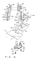
- the leg section 15a is formed of a rear leg segment 16 protruding from the base panel 10a and being integral therewith, and a front leg segment 17 removably fastened to the front of the rear leg segment 16.
- the front leg segment 17 has a claw 18 projecting from the side which connects to the rear leg segment 16. The claw 18 is positioned so that it engages the lock hole 19 formed in the inner side of the rear leg segment 16, with respect to the display unit 8 whereby the segments 16 and 17 are fastened together, forming the leg section 15a.
- the leg segments 16 and 17, thus fastened together, define a guide path 20.
- the front leg segment 17 also has a guide portion 21 for guiding a cable into the housing 9.
- the guide portion 21 has a communication port 22 at its tip.
- the port 22 opens to the interior of the housing 9, thus allowing the guide path 20 to communicate with the interior of the housing 9.
- the segment 17 further has a fixing tongue piece 24 which is attached to the guide portion 21 and aligns with the boss 23 protruding from the base panel 10a, and has a positioning hole 25.
- a positioning projection 26, protruding from the base panel 10a is inserted in the hole 25, thereby aligning the front leg segment 17 with respect to the rear leg segment 16.
- the leg segments 16 and 17 are firmly connected by means of a screw 27 set in screw 27 engagement with the boss 23, thus forming the leg section 15a.
- the stepped portion of the front leg segment 17, which is continuous to the guide portion 21, has a hole 28 opening into the interior of the leg segment 17.
- a tongue piece 29, protruding from the front panel 10b, is inserted in the hole 28, thus positioning the front panel 10b with respect to the base panel 10a.
- the leg segments 16 and 17 have, respectively half-cylinders 31a and 31b, which are situated on the outer sides and connected to each other.
- the half-cylinders 31a and 31b define U-shaped notches 30a and 30b.
- These half-cylinders 31a and 31b form a hollow shaft 32 having a guide path 33.
- the guide path 33 communicates with the guide path 20 defined by the leg segments 16 and 17.
- the half-cylinder 31a of the rear leg segment 16 has two arcuate projections 34a and 34b opposing each other and extending into the front leg segment 17.
- the distance L1 between the tips of the arcuate projections 34a and 34b is shorter than the inside diameter L2 of the hollow shaft 32.
- the leg section 15a of the housing 9 extends into the recess 6a of the case 2.
- an opening 38 is formed in the recess 6a.
- This opening 38 consists of two sections 39 and 40.
- the section 39 is cut in the outermost of the two opposing side walls which define the inner and outer faces of the recess 6a with respect to the case 2, and the section 40 is made in the face which defines the bottom of the recess 6a.
- the upper edge of the section 39, or receiving section 41, is arcuate, so that the shaft 32 is rotatably fitted in the opening 38.
- a support 43 which is made of a synthetic resin, is located in the opening 38, extending from below the top cover 4.
- the support 43 is fastened to the wall defining the bottom of the recess 6a, and consists of a side wall 44 and a bottom 45 which are fitted in the sections 39 and 40 of the opening 38, respectively, and two flanges 46, connected to the front and rear edges of the section 39, and fastened to the bosses 47 which protrude downward from the inner surface of the top cover 4, by means of screws 48.
- An arcuate notch 50, into which the shaft 32 is rotatably fitted, is cut in the upper edge of the side wall 44, so as to oppose the receiving section 41 in the case 2, and this notch 50 and the section 41 form a circular hole 51, through which the shaft 32 rotatably extends.
- a guide wall 52, which is taller than the side wall 44 and also has an arcuate notch, is formed integral with the wall 44.
- the hole 51 communicates with the guide path 20 formed in the leg section 15a through the guide path 33 formed in the shaft 32.
- the guide paths 20 and 33 and the hole 51 connects the interior of the case 2 to that of the housing 9, and a cable 53 extends through the paths 20 and 33 and the hole 51, thus electrically connecting the printed circuit board 7 to the liquid-crystal display 11.
- the cable 53 is flexible and has connectors 54a and 54b attached to its ends as is shown in Fig. 7.
- the connectors 54a and 54b are elongated members than the hole 51.
- the connector 54a extends into the case 2 and is connected to the printed circuit board 7, and the connector 54b extends into the housing 9 and is connected to the liquid-crystal display 11.
- the front panel 10b and the front leg segment 17 are removed from the base panel 10a of the housing 9. Also, the top cover 4 is detached from the bottom case 3. Further, the support 43 is removed from the top cover 4, thus allowing access to the interior of the case 2 through the opening 38 which is, as is shown in Fig. 6, formed in the left of the two opposing side walls which define the left and right faces of the recess 6a, and the wall which define the bottom of the recess 6a.
- the opening 38 is larger than the connector 54a to be attached to the printed circuit board 7. That end portion of the cable 53 to which the connector 54a is connected is inserted into the case 2 through the opening 38.
- the support 43 is fitted into the opening 38 from within the top cover 4, with the cable 53 rested in the U-notch 50 of the support 42.
- the flanges 46 of the support 43 are then fastened to the bosses 47 by screws 48.
- the support 43 is secured to the housing 9, whereby the U-notch 50 of the support 43 and the receiving section 41 of the top cover 4 define the hole 51, and the cable 53 passes through this hole 51.
- the cable 53 is pushed into the half-cylinder 31a of the rear leg segment 16, more precisely into the gap between the arcuate projections 34a and 34b.
- the cable 53 can hardly slip out of it since the distance L2 between the tips of the arcuate projections 34a and 34b is shorter than the inside diameter L1 of the hollow shaft 32.
- the rear leg segment 16 is inserted into the recess 6a, thus fitting cylinder 31a into the hole 51.
- the cable 53 is guided through the rear leg segment 16 to a position above the base panel 10a.
- the front leg section 17 is fastened to the rear leg section 16 by means of the screw 27, thus fitting the half-cylinder 31b into the hole 51.
- the half-cylinders 31a and 31b form the hollow shaft 32 having the guide path 33, through which the cable 53 extends into the housing 9 of the display unit 8.
- the cable 53 is guided from the case 2 into the housing 9 through the leg section 15a.
- the leg section 15b of the housing 9 is composed of a rear leg segment 60 formed so as to be integral with the base panel 10a and a front leg segment 61 formed so as to be integral with the front panel lub, and is similar to the leg section 15a in structure.
- the leg section 15b extends horizontally longer than the leg section 15a, and contains a pair of hinge mechanisms 62, which support the housing 9 such that it can be rotated upward from the other case 2 and downward thereto.
- the first and second hinge mechanisms are located in the inner and outer ends of the leg section 15b, respectively.
- the hinge mechanism 62 is designed not only to support the housing 9, but also to hold it at any position between the closed position and the opened position.
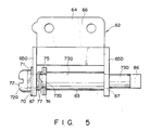
- the hinge mechanisms 62 are identical in structure, and only one of them will, therefore, be described in detail with reference to Fig. 5.
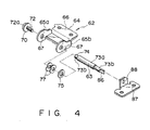
- either hinge mechanism 62 has a straight shaft 63 and a bracket 64 made of metal and supporting the shaft 63.
- the bracket 64 comprises a pair of support pieces 65a and 65b spaced apart in the axial direction of the shaft 63, and a fixing section 66 connecting these pieces 65a and 65b.
- the support pieces 65a and 65b each have a hole 67, and are so positioned that the holes 67 are coaxial.
- the ends of the shaft 63 are rotatably supported in these holes 67.
- the left end of shaft 63 has a screw hole, and a screw 72 is inserted in this hole, with a plain washer 70 and a spring washer 71 interposed between it and the left end of the shaft 63.
- the plain washer 70, the spring washer 71, and the head 72a of the screw 72 have diameters larger than those of holes 67.
- the plain washer 70 abuts on the outer side of support piece 65a, whereby the washers 70 and 71 and the screw 72 prevent the shaft 63 from slipping from the hinge mechanism 62.
- the shaft 63 consists of three portions, i.e., a thick portion 73a and two thin portions 73b extending from the ends of the portion 73a.
- the first thin portion 73b is inserted in the hole 67 of the support pieces 65b, and the second thin portion 73b is inserted in the hole 67 of the support piece 65a.
- a plain washer 75 having an outside diameter larger than the diameter of the thick portion 73a is mounted on the thin portion 73b and abuts the right end 74 of the thick portion 73a.
- Two wave washers 77 having an outside diameter substantially the same as the diameter of the thick portion 73a are mounted on the thin portion 73b and compressed between the plain washer 75 and the support piece 65a of the bracket 64.
- the two wave washers 77 which function as springs, abut on the plain washer 75 and the support piece 65a, respectively. A friction force is thereby generated between the plain washer 75 and the bracket 64, restricting the rotation of the shaft 63 which is supported by the bracket 64.
- two wave washers 77 are used to restrict the rotation of the shaft 63.
- one wave washer, or three or more wave washers may be used for the same purpose in the present invention.
- two pairs of bosses 80 protrude from the inner surface of the rear leg segment 60.
- the fixing sections 66 of the first and second hinge mechanisms 62 are fastened to the first and second pairs of bosses 80, respectively, by means of screws 81, whereby both hinge mechanisms 62 are coupled to the housing 9.
- one of the screws 81 which fasten either fixing section 66 to the bosses 80 passes through the hole cut in the front leg segment 61, and thus fastens the front leg segment 61 to the rear leg segment 60.
- a decoration cover 82 is removably connected to the front leg segment 61, thus concealing the heads 81a of the screws 81.
- one of the thin portions 73b of either shaft 63 extends into case 2 through the hole 85 made in the side wall of case 2. That end 86 of the portion 73b which is located within the case 2 has a polygonal cross section. The end 86 of the thin portion 73b is fitted in the corresponding hole 88 made in the support 87 which protrudes downward from the top wall of case 2. Thus, the shaft 63 of the hinge mechanism 62 cannot rotate.
- the display unit 8 has its leg section 15a connected to the case 2 by means of the shaft 32 held in the hole 51 as is shown in Figs. 6 and 7, and has its leg section 15b connected to the case 2 by means of the hinge mechanisms 62 as is shown in Figs. 2 and 3.
- the unit 8 is thus rotatably supported on the case 2.
- hinge mechanisms 62 operate to ho1d the display unit 8 at any desired position between the closed position and the opened position.
- the bracket 64 of the mechanism 62 which is fastened to the base panel 10a, rotates around the shaft 63, allowing the unit 8 to rotated to any position between the closed position and the opened position, so that the user of the personal computer can see clearly the data displayed on the liquid-crystal display screen 12.
- the two wave washers 77 can easily be incorporated in the hinge mechanism 62, when pushed into the gap between the support piece 65a and the plain washer 75. Once so incorporated, the washers 77 can exert a frictional force between the shaft 63 and the bracket 64. Unlike the coil spring used in the conventional hinge described above, the wave washers 77 need not be machined with high precision, or positioned in the hinge mechanism 62 with high precision. Therefore, the hinge mechanism 62 can be manufactured at lower cost than the conventional hinge.
- the hinge mechanism 62 is much shorter than the conventional hinge.
- Fig. 13 illustrates a hinge mechanism according to a second embodiment of the invention.
- This mechanism is different from the first embodiment (Fig. 5), in that a flange 91 is formed integral with the shaft 63, located between the thick portion 73a and the thin portion 73b, and has a larger diameter than the thick portion 73a.
- Two wave washers 77 are mounted on the thin portion 73b and compressed between the flange 91 and the support piece 65a of the bracket 64.
- Fig. 14 shows a hinge mechanism according to a third embodiment of the invention, which is identical to the first embodiment (Fig. 5), except that a bellevill spring 100 is used in place of wave washers.
- the hinge device according to the invention can be used, not only in personal computer, but also in word processors, reclining seats, and the like.
Abstract
Description
- The present invention relates to a hinge device for use in a portable apparatus such as a lap-top or portable personal computer and more particularly to a hinge device having a mechanism for stopping a movable member of the apparatus at an open position, by virtue of the frictional force exerted by a spring member.
- U.S. Patent 4,571,456 discloses a portable personal computer which comprises a rectangular case, a keyboard attached to the case, and a display unit hinged to the case by a hinge.
- Connected by the hinge to the case, the display unit can rotate between a position (hereinafter referred to as "closed position") where it covers the keyboard and a position (hereinafter referred to as "opened position") where it stands upright at the rear of the keyboard. The hinge includes a mechanism which experts a frictional force to stop the display unit at any position between the closed position and the open position.
- A hinge having such a mechanism and designed to connect a display unit to the case of a personal computer is disclosed in Published Unexamined Japanese Patent Application No. 59-99111. This hinge comprises a shaft and a coil spring wound around the shaft. The shaft is fastened at one end to the display unit and at the other end to the case. As the display unit is rotated upward, the coil spring is wound more and more tightly around the shaft, whereby a frictional force is generated between the shaft and the coil spring. By virtue of this force, the display unit is held up at a position where the user takes his or her hand off the display unit, provided that the hinge shaft and the coil spring have a proper outside diameter and an appropriate inside diameter, respectively, and are set at correct positions. It requires much time and labor to make the shaft and the spring with sufficient precision and to set them in a correct positional relationship. Consequently, the manufacturing cost of the hinge is inevitably high.
- The object of the present invention is to provide a hinge device whose components need not be machined or positioned with high-precision, and which is therefore easy to manufacture and can, thus, be manufactured at low cost.
- According to the invention, there is provided a hinge device comprising: a shaft to be connected at one end to a first member; support means mounted on the shaft, for supporting a second member such that the second member rotates around the shaft; and ring-shaped spring means held and compressed between the shaft and the support means, for generating a friction between said shaft and said support means when the first and second members are rotated relative to each other around the shaft, thereby to suppress the rotation of the first and second members.
- The ring-shaped spring means can easily be incorporated in the hinge device, when pushed into the gap between the shaft and the support means. Once so incorporated, the ring-shaped spring means can exert a frictional force between the shaft and the support means. Unlike the coil spring used in the conventional hinge described above, the spring means need not be machined or positioned with high precision.
- This invention can be more fully understood from the following detailed description when taken in conjunction with the accompanying drawings, in which:
- Fig. 1 is a perspective view illustrating a personal computer having a hinge device according to the present invention;
- Fig. 2 is a sectional view schematically showing a hinge device according to a first embodiment of the present invention;
- Fig. 3 is a sectional view, taken along line III-III in Fig. 2;
- Fig. 4 is an exploded view illustrating the hinge device shown in Fig. 2;
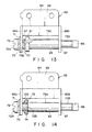
- Fig. 5 is a plan view of the hinge device shown in Fig. 2;
- Fig. 6 consists of a perspective view showing a part of the case of the computer and an exploded view showing hinge mechanism for connecting a display unit to the case;
- Fig. 7 is a sectional view schematically showing how the the housing and display unit of the personal computer are coupled to each other;
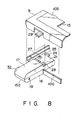
- Fig. 8 is an exploded view showing the leg section which supports the display unit;
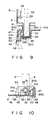
- Fig. 9 is another sectional view, explaining how the cable is guided from the housing into the display unit through the hinge device shown in Figs. 6 and 7;
- Fig. 10 is a sectional view, taken along line X-X in Fig. 7;
- Fig. 11 is a sectional view showing the shaft and other components of the hinge device shown in Figs. 6 and 7;
- Fig. 12 is a partially sectional, side view of the display unit;
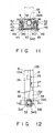
- Fig. 13 is a plan view showing a hinge device according to a second embodiment of the invention; and
- Fig. 14 is a plan view illustrating a hinge device according to a third embodiment of the invention.
- Fig. 1 illustrates a lap-top or portable personal computer 1. The computer 1 has a
case 2 made of a synthetic resin and is shaped like a thin rectangular box comprising abottom case 3 which is covered by atop cover 4. Akeyboard 5 is attached to the front half of thetop cover 4. The rearmost part of the half of thetop cover 4 is thicker than the front most part of the rear half. Tworecesses top cover 4, respectively. As is shown in Fig. 7, a printedcircuit board 7, on which are mounted a number of circuit parts (not shown), is incorporated in thecase 2. - As is illustrated in Fig. 1, the computer 1 further comprises a flat-panel
type display unit 8 located at the rear of thekeyboard 5. Thedisplay unit 8 comprises arectangular housing 9 and a flat liquid-crystal display 11 located within thehousing 9. Thehousing 9 is composed of abase panel 10a and a front panel 10b, both shaped like a rectangular plate. Thesepanels 10a and 10b are fastened together, by means of screws (not shown) at their four corners. The liquid-crystal display 11, which has ascreen 12, is inter posed between thepanels 10a and 10b. Thescreen 12 is exposed through therectangular opening 13 made in the front panel 10b. - As is evident from Fig. 1, the
display unit 8 is attached to thecase 2 such that it rotate between a position (hereinafter referred to as "closed position") where it covers thekeyboard 6 and a position (herein after referred to as "opened position") where it stands upright at the rear of thekeyboard 5. Thedisplay unit 8 covers theentire keyboard 5 when it is rotated to the closed position. As long as theunit 8 remains in the closed position, its top is at the same level as the upper surface of thetop cover 4, and its left and right sides are level with those of thetop cover 4. In this condition, thecase 2 and thedisplay unit 8 form a relatively thin box, which is quite portable. - As is shown in Figs. 2 and 6, a pair of
leg sections housing 9, with their lower ends located in therecesses case 2. Theleg sections - As is evident from Fig. 6, the
leg section 15a is formed of arear leg segment 16 protruding from thebase panel 10a and being integral therewith, and afront leg segment 17 removably fastened to the front of therear leg segment 16. As Fig. 6 clearly shows, thefront leg segment 17 has aclaw 18 projecting from the side which connects to therear leg segment 16. Theclaw 18 is positioned so that it engages thelock hole 19 formed in the inner side of therear leg segment 16, with respect to thedisplay unit 8 whereby thesegments leg section 15a. Theleg segments guide path 20. - The
front leg segment 17 also has aguide portion 21 for guiding a cable into thehousing 9. Theguide portion 21 has acommunication port 22 at its tip. Theport 22 opens to the interior of thehousing 9, thus allowing theguide path 20 to communicate with the interior of thehousing 9. Thesegment 17 further has afixing tongue piece 24 which is attached to theguide portion 21 and aligns with theboss 23 protruding from thebase panel 10a, and has apositioning hole 25. Apositioning projection 26, protruding from thebase panel 10a, is inserted in thehole 25, thereby aligning thefront leg segment 17 with respect to therear leg segment 16. As a result of this, theleg segments screw 27 set inscrew 27 engagement with theboss 23, thus forming theleg section 15a. - As is illustrated in Fig. 8, the stepped portion of the
front leg segment 17, which is continuous to theguide portion 21, has ahole 28 opening into the interior of theleg segment 17. Atongue piece 29, protruding from the front panel 10b, is inserted in thehole 28, thus positioning the front panel 10b with respect to thebase panel 10a. - As may be understood from Fig. 6, the
leg segments cylinders cylinders notches cylinders hollow shaft 32 having aguide path 33. Theguide path 33 communicates with theguide path 20 defined by theleg segments - As is best shown in Fig. 6, the half-
cylinder 31a of therear leg segment 16 has twoarcuate projections front leg segment 17. Thus, as is illustrated in Fig. 12, the distance L1 between the tips of thearcuate projections hollow shaft 32. - The
leg section 15a of thehousing 9 extends into therecess 6a of thecase 2. As is evident from Fig. 6, anopening 38 is formed in therecess 6a. Thisopening 38 consists of twosections section 39 is cut in the outermost of the two opposing side walls which define the inner and outer faces of therecess 6a with respect to thecase 2, and thesection 40 is made in the face which defines the bottom of therecess 6a. The upper edge of thesection 39, or receivingsection 41, is arcuate, so that theshaft 32 is rotatably fitted in theopening 38. - A
support 43, which is made of a synthetic resin, is located in theopening 38, extending from below thetop cover 4. Thesupport 43 is fastened to the wall defining the bottom of therecess 6a, and consists of aside wall 44 and a bottom 45 which are fitted in thesections opening 38, respectively, and twoflanges 46, connected to the front and rear edges of thesection 39, and fastened to thebosses 47 which protrude downward from the inner surface of thetop cover 4, by means ofscrews 48. - An
arcuate notch 50, into which theshaft 32 is rotatably fitted, is cut in the upper edge of theside wall 44, so as to oppose the receivingsection 41 in thecase 2, and thisnotch 50 and thesection 41 form acircular hole 51, through which theshaft 32 rotatably extends. Aguide wall 52, which is taller than theside wall 44 and also has an arcuate notch, is formed integral with thewall 44. - The
hole 51 communicates with theguide path 20 formed in theleg section 15a through theguide path 33 formed in theshaft 32. Hence, theguide paths hole 51 connects the interior of thecase 2 to that of thehousing 9, and acable 53 extends through thepaths hole 51, thus electrically connecting the printedcircuit board 7 to the liquid-crystal display 11. Thecable 53 is flexible and hasconnectors connectors hole 51. Theconnector 54a extends into thecase 2 and is connected to the printedcircuit board 7, and theconnector 54b extends into thehousing 9 and is connected to the liquid-crystal display 11. - It will now be explained how the
cable 53 is guided from thecase 2 into thehousing 9 of thedisplay unit 8, withdisplay unit 8 disconnected fromcase 2. - First, the front panel 10b and the
front leg segment 17 are removed from thebase panel 10a of thehousing 9. Also, thetop cover 4 is detached from thebottom case 3. Further, thesupport 43 is removed from thetop cover 4, thus allowing access to the interior of thecase 2 through theopening 38 which is, as is shown in Fig. 6, formed in the left of the two opposing side walls which define the left and right faces of therecess 6a, and the the wall which define the bottom of therecess 6a. Theopening 38 is larger than theconnector 54a to be attached to the printedcircuit board 7. That end portion of thecable 53 to which theconnector 54a is connected is inserted into thecase 2 through theopening 38. - Next, the
support 43 is fitted into the opening 38 from within thetop cover 4, with thecable 53 rested in the U-notch 50 of the support 42. Theflanges 46 of thesupport 43 are then fastened to thebosses 47 byscrews 48. As a result, thesupport 43 is secured to thehousing 9, whereby the U-notch 50 of thesupport 43 and the receivingsection 41 of thetop cover 4 define thehole 51, and thecable 53 passes through thishole 51. - Then, the
cable 53 is pushed into the half-cylinder 31a of therear leg segment 16, more precisely into the gap between thearcuate projections cable 53 is thus pushed into the half-cylinder 31a, it can hardly slip out of it since the distance L2 between the tips of thearcuate projections hollow shaft 32. Therear leg segment 16 is inserted into therecess 6a, thusfitting cylinder 31a into thehole 51. - Thereafter, the
cable 53 is guided through therear leg segment 16 to a position above thebase panel 10a. This done, thefront leg section 17 is fastened to therear leg section 16 by means of thescrew 27, thus fitting the half-cylinder 31b into thehole 51. The half-cylinders hollow shaft 32 having theguide path 33, through which thecable 53 extends into thehousing 9 of thedisplay unit 8. Thus, thecable 53 is guided from thecase 2 into thehousing 9 through theleg section 15a. - As is illustrated in Figs. 2 and 3, the
leg section 15b of thehousing 9 is composed of arear leg segment 60 formed so as to be integral with thebase panel 10a and afront leg segment 61 formed so as to be integral with the front panel lub, and is similar to theleg section 15a in structure. Theleg section 15b extends horizontally longer than theleg section 15a, and contains a pair ofhinge mechanisms 62, which support thehousing 9 such that it can be rotated upward from theother case 2 and downward thereto. - The first and second hinge mechanisms are located in the inner and outer ends of the
leg section 15b, respectively. Thehinge mechanism 62 is designed not only to support thehousing 9, but also to hold it at any position between the closed position and the opened position. Thehinge mechanisms 62 are identical in structure, and only one of them will, therefore, be described in detail with reference to Fig. 5. - As is illustrated in Fig. 5, either
hinge mechanism 62 has astraight shaft 63 and abracket 64 made of metal and supporting theshaft 63. Thebracket 64 comprises a pair ofsupport pieces shaft 63, and a fixingsection 66 connecting thesepieces support pieces hole 67, and are so positioned that theholes 67 are coaxial. The ends of theshaft 63 are rotatably supported in theseholes 67. - The left end of
shaft 63 has a screw hole, and ascrew 72 is inserted in this hole, with aplain washer 70 and aspring washer 71 interposed between it and the left end of theshaft 63. Theplain washer 70, thespring washer 71, and thehead 72a of thescrew 72 have diameters larger than those ofholes 67. Hence, theplain washer 70 abuts on the outer side ofsupport piece 65a, whereby thewashers screw 72 prevent theshaft 63 from slipping from thehinge mechanism 62. - The
shaft 63 consists of three portions, i.e., athick portion 73a and twothin portions 73b extending from the ends of theportion 73a. The firstthin portion 73b is inserted in thehole 67 of thesupport pieces 65b, and the secondthin portion 73b is inserted in thehole 67 of thesupport piece 65a. Aplain washer 75 having an outside diameter larger than the diameter of thethick portion 73a is mounted on thethin portion 73b and abuts theright end 74 of thethick portion 73a. Twowave washers 77 having an outside diameter substantially the same as the diameter of thethick portion 73a are mounted on thethin portion 73b and compressed between theplain washer 75 and thesupport piece 65a of thebracket 64. The twowave washers 77, which function as springs, abut on theplain washer 75 and thesupport piece 65a, respectively. A friction force is thereby generated between theplain washer 75 and thebracket 64, restricting the rotation of theshaft 63 which is supported by thebracket 64. - In this embodiment, two
wave washers 77 are used to restrict the rotation of theshaft 63. Alternatively, one wave washer, or three or more wave washers may be used for the same purpose in the present invention. - As is shown in Fig. 2, two pairs of
bosses 80 protrude from the inner surface of therear leg segment 60. The fixingsections 66 of the first andsecond hinge mechanisms 62 are fastened to the first and second pairs ofbosses 80, respectively, by means ofscrews 81, whereby both hingemechanisms 62 are coupled to thehousing 9. As is shown in Fig. 3, one of thescrews 81 which fasten either fixingsection 66 to thebosses 80 passes through the hole cut in thefront leg segment 61, and thus fastens thefront leg segment 61 to therear leg segment 60. Adecoration cover 82 is removably connected to thefront leg segment 61, thus concealing the heads 81a of thescrews 81. - As is illustrated in Fig. 2, one of the
thin portions 73b of eithershaft 63 extends intocase 2 through thehole 85 made in the side wall ofcase 2. Thatend 86 of theportion 73b which is located within thecase 2 has a polygonal cross section. Theend 86 of thethin portion 73b is fitted in the correspondinghole 88 made in thesupport 87 which protrudes downward from the top wall ofcase 2. Thus, theshaft 63 of thehinge mechanism 62 cannot rotate. - The
display unit 8 has itsleg section 15a connected to thecase 2 by means of theshaft 32 held in thehole 51 as is shown in Figs. 6 and 7, and has itsleg section 15b connected to thecase 2 by means of thehinge mechanisms 62 as is shown in Figs. 2 and 3. Theunit 8 is thus rotatably supported on thecase 2. - It will now be explained how either hinge
mechanisms 62 operate to ho1d thedisplay unit 8 at any desired position between the closed position and the opened position. - When the
display unit 8 is rotated from the closed position toward the opened position, thebracket 64 of themechanism 62, which is fastened to thebase panel 10a, rotates around theshaft 63, allowing theunit 8 to rotated to any position between the closed position and the opened position, so that the user of the personal computer can see clearly the data displayed on the liquid-crystal display screen 12. - Since the
wave washers 77 are interposed and compressed between theplain washer 75 mounted on theshaft 63 and thesupport piece 65a of thebracket 64, a frictional force is generated between thebracket 64 and theplain washer 75. This force suppresses the rotation of thebracket 64, whereby thedisplay unit 8 remains at the position where the user takes his or her hand off thedisplay unit 8. - The two
wave washers 77 can easily be incorporated in thehinge mechanism 62, when pushed into the gap between thesupport piece 65a and theplain washer 75. Once so incorporated, thewashers 77 can exert a frictional force between theshaft 63 and thebracket 64. Unlike the coil spring used in the conventional hinge described above, thewave washers 77 need not be machined with high precision, or positioned in thehinge mechanism 62 with high precision. Therefore, thehinge mechanism 62 can be manufactured at lower cost than the conventional hinge. - Further, since the total thickness of the two
wave washers 77 is far less than the length of the coil spring wound around the hinge shaft in the conventional hinge, thehinge mechanism 62 is much shorter than the conventional hinge. - Fig. 13 illustrates a hinge mechanism according to a second embodiment of the invention. This mechanism is different from the first embodiment (Fig. 5), in that a
flange 91 is formed integral with theshaft 63, located between thethick portion 73a and thethin portion 73b, and has a larger diameter than thethick portion 73a. Twowave washers 77 are mounted on thethin portion 73b and compressed between theflange 91 and thesupport piece 65a of thebracket 64. - Fig. 14 shows a hinge mechanism according to a third embodiment of the invention, which is identical to the first embodiment (Fig. 5), except that a
bellevill spring 100 is used in place of wave washers. - The hinge device according to the invention can be used, not only in personal computer, but also in word processors, reclining seats, and the like.
Claims (11)
ring-shaped spring means (77, 100) held and compressed between said shaft (63) and said support means (64), for generating a friction between said shaft (63) and said support means (64) when the first and second members (2, 8) are rotated relative to each other around said shaft (63), thereby to suppress the rotation of the first and second members (2, 8).
a shaft (63) to be connected at one end to the case (2);
support means (64) mounted on the shaft (63), for supporting the image-displaying unit (8) such that the image-displaying unit (8) rotates around said shaft (63); and
ring-shaped spring means (77, 100) held and compressed between said shaft (63) and said support means (64), for generating a friction between said shaft (63) and said support means (64) when the case (2) and the image-displaying unit (8) are rotated relative to each other around said shaft (63), thereby to suppress the rotation of the case (2) and the image-displaying unit (8).
Applications Claiming Priority (2)
| Application Number | Priority Date | Filing Date | Title |
|---|---|---|---|
| JP16222789A JP2880729B2 (en) | 1989-06-23 | 1989-06-23 | Small electronic equipment |
| JP162227/89 | 1989-06-23 |
Publications (3)
| Publication Number | Publication Date |
|---|---|
| EP0404166A2 true EP0404166A2 (en) | 1990-12-27 |
| EP0404166A3 EP0404166A3 (en) | 1991-12-11 |
| EP0404166B1 EP0404166B1 (en) | 1995-09-27 |
Family
ID=15750389
Family Applications (1)
| Application Number | Title | Priority Date | Filing Date |
|---|---|---|---|
| EP19900111798 Expired - Lifetime EP0404166B1 (en) | 1989-06-23 | 1990-06-21 | Hinge device having mechanism for stopping movable member at open position |
Country Status (5)
| Country | Link |
|---|---|
| US (2) | US5081742A (en) |
| EP (1) | EP0404166B1 (en) |
| JP (1) | JP2880729B2 (en) |
| KR (1) | KR930007436B1 (en) |
| DE (1) | DE69022636T2 (en) |
Cited By (4)
| Publication number | Priority date | Publication date | Assignee | Title |
|---|---|---|---|---|
| GB2309740A (en) * | 1996-02-01 | 1997-08-06 | Canon Business Machines Inc | A friction hinge for a foldable portable computer |
| FR2763711A1 (en) * | 1997-05-24 | 1998-11-27 | Lg Electronics Inc | METHOD AND DEVICE FOR MOUNTING A LIQUID CRYSTAL DISPLAY MODULE |
| US6807712B2 (en) | 2000-06-29 | 2004-10-26 | Nokia Mobile Phones Ltd. | Hinge having engagement surface to restrain rotational movement and electronic device containing such a hinge |
| US7404236B2 (en) * | 2001-12-24 | 2008-07-29 | Lg Electronics, Inc. | Hinge assembly for flat panel display appliance |
Families Citing this family (38)
| Publication number | Priority date | Publication date | Assignee | Title |
|---|---|---|---|---|
| US5240427A (en) * | 1989-06-23 | 1993-08-31 | Kabushiki Kaisha Toshiba | Portable apparatus having cable electrically connecting display unit and base unit |
| US5238421A (en) * | 1989-06-23 | 1993-08-24 | Kabushiki Kaisha Toshiba | Portable apparatus having cable electrically connecting display unit and base unit |
| JP2786677B2 (en) * | 1989-06-23 | 1998-08-13 | 株式会社東芝 | Small electronic equipment |
| US5217316A (en) * | 1990-10-12 | 1993-06-08 | Nhk Spring Co., Ltd. | Slow-acting rotation shaft device |
| DE9203183U1 (en) * | 1992-03-10 | 1993-07-15 | Siemens Nixdorf Informationssysteme Ag, 4790 Paderborn, De | |
| US5279907A (en) * | 1992-05-11 | 1994-01-18 | Emerson Electric Co. | Safety vent for a container and method of making the same |
| JPH0589762U (en) * | 1992-05-11 | 1993-12-07 | 株式会社ニフコ | Hinge device |
| US5552967A (en) * | 1993-04-30 | 1996-09-03 | Kabushiki Kaisha Toshiba | Portable electronic apparatus having a housing for containing circuits board and functional components |
| US5583744A (en) * | 1994-09-06 | 1996-12-10 | Citizen Watch Co., Ltd. | Portable computer with detachable battery pack |
| US5772351A (en) * | 1995-01-24 | 1998-06-30 | Chih Ching Industry Ltd. | Pivot joint |
| US5542152A (en) * | 1995-05-08 | 1996-08-06 | International Business Machines Corporation | Shaft assembly for a tilt adjustment mechanism |
| US5566424A (en) * | 1995-05-08 | 1996-10-22 | International Business Machines Corporation | Tilt adjustment mechanism |
| KR19980034367A (en) * | 1996-11-03 | 1998-08-05 | 김광호 | Liquid crystal display device having power supply and signal part in the stand part |
| KR100212313B1 (en) | 1996-11-06 | 1999-08-02 | 윤종용 | Lcd display device |
| KR19980034365A (en) * | 1996-11-06 | 1998-08-05 | 김광호 | Balanced LCD Display |
| DE69832752T2 (en) * | 1997-05-06 | 2006-09-07 | Samsung Electronics Co., Ltd., Suwon | Swivel device and portable computer with swivel device |
| KR19990024492U (en) * | 1997-12-12 | 1999-07-05 | 윤종용 | Flat panel display device with hinged device for tilt operation |
| US6018847A (en) * | 1998-07-02 | 2000-02-01 | Lu; Sheng-Nan | Hinge axle device for a LCD monitor |
| US6198625B1 (en) * | 1999-06-03 | 2001-03-06 | Micron Electronics, Inc. | Hinge assembly for a portable computer |
| US6388351B1 (en) * | 1999-12-30 | 2002-05-14 | General Electric Company | Bearing load washer |
| KR100364732B1 (en) * | 2000-07-08 | 2002-12-16 | 엘지전자 주식회사 | Hinge assembly in LCD monitor |
| US6430777B1 (en) * | 2001-04-04 | 2002-08-13 | Lu Sheng-Nan | Pivot device for a notebook computer |
| US20030089832A1 (en) * | 2001-11-02 | 2003-05-15 | Gold Robert J. | Multi-function accessory for handheld electronics |
| TW511860U (en) * | 2001-11-08 | 2002-11-21 | Wistron Corp | Electronic equipment with side-fixed apparatus for anti-deviation |
| KR100443613B1 (en) * | 2001-12-27 | 2004-08-09 | 엘지전자 주식회사 | Hinge structure for plane-type display device |
| TW566580U (en) * | 2002-01-30 | 2003-12-11 | Chung-Nan Hsieh | Pivotal hinge and slit-type conical elastic pad |
| US6859980B2 (en) | 2002-06-06 | 2005-03-01 | Austin R. Baer | Covered pinned hinge |
| US6796541B2 (en) * | 2002-08-29 | 2004-09-28 | Shin Zu Shing Co., Ltd. | Support for an LCD monitor |
| US6804859B2 (en) * | 2003-01-10 | 2004-10-19 | Shin Zu Shing Co., Ltd. | Securing device for a laptop computer hinge to avoid damping of a screen when the screen is away from mainframe of the laptop computer |
| US20050039301A1 (en) * | 2003-08-22 | 2005-02-24 | Lu Sheng-Nan | Hinge assembly |
| US20050268431A1 (en) * | 2004-05-19 | 2005-12-08 | Huan-Chen Lo | Support and angle adjustable device for monitors |
| US7089628B2 (en) * | 2004-09-16 | 2006-08-15 | Quanta Computer, Inc. | Hinge design for a computer |
| CN100445584C (en) * | 2005-08-26 | 2008-12-24 | 鸿富锦精密工业(深圳)有限公司 | Hinge |
| US20070174997A1 (en) * | 2006-01-27 | 2007-08-02 | Shin Zu Shing Co., Ltd. | Suspension hinge |
| TWI292643B (en) * | 2006-09-01 | 2008-01-11 | Compal Electronics Inc | Hinge structure and fodable apparatus using the same |
| JP6513501B2 (en) * | 2015-06-15 | 2019-05-15 | 大豊工業株式会社 | Washer manufacturing method and washer |
| JP6208916B2 (en) * | 2015-09-24 | 2017-10-04 | スガツネ工業株式会社 | Hinge |
| US11113095B2 (en) | 2019-04-30 | 2021-09-07 | Automation Anywhere, Inc. | Robotic process automation system with separate platform, bot and command class loaders |
Citations (4)
| Publication number | Priority date | Publication date | Assignee | Title |
|---|---|---|---|---|
| CH493751A (en) * | 1968-07-11 | 1970-07-15 | Dalcher Willy Maschinenmeister | Adjustable articulation |
| DE2402815A1 (en) * | 1974-01-22 | 1975-07-24 | Braun Ag | Housing for electronic devices - consists of lower part with plastic cover held by bolt about which it can rotate |
| US4571456A (en) * | 1982-10-18 | 1986-02-18 | Grid Systems Corporation | Portable computer |
| FR2614077A1 (en) * | 1987-04-17 | 1988-10-21 | Treves Ets | Improvements to the mounting of an articulation pin |
Family Cites Families (9)
| Publication number | Priority date | Publication date | Assignee | Title |
|---|---|---|---|---|
| US959099A (en) * | 1910-02-14 | 1910-05-24 | Frank O Anderson | Pivotal support for mirrors. |
| US1004237A (en) * | 1911-02-06 | 1911-09-26 | Arthur Brandes | Friction-locked hinge. |
| US1734005A (en) * | 1928-01-11 | 1929-10-29 | Gen Motors Corp | Windshield-stanchion joint |
| BE490570A (en) * | 1948-09-01 | |||
| BE510993A (en) * | 1951-04-30 | |||
| CH330405A (en) * | 1955-05-25 | 1958-06-15 | Aluco Bauelemente Patentgesell | Pivot bearing arrangement on room closure elements with pivoting sash |
| US4018104A (en) * | 1975-03-17 | 1977-04-19 | Caterpillar Tractor Co. | Frictionally held control linkage for engine throttle controls and the like |
| JPS5999111A (en) * | 1982-11-29 | 1984-06-07 | Nhk Spring Co Ltd | Locking device for shaft |
| US4730364A (en) * | 1985-10-29 | 1988-03-15 | Bondwell Holding Ltd. | Data processor flush hinge assembly |
-
1989
- 1989-06-23 JP JP16222789A patent/JP2880729B2/en not_active Expired - Fee Related
-
1990
- 1990-06-21 DE DE1990622636 patent/DE69022636T2/en not_active Expired - Fee Related
- 1990-06-21 EP EP19900111798 patent/EP0404166B1/en not_active Expired - Lifetime
- 1990-06-22 US US07/542,119 patent/US5081742A/en not_active Expired - Lifetime
- 1990-06-22 KR KR1019900009234A patent/KR930007436B1/en not_active IP Right Cessation
-
1995
- 1995-02-10 US US08/386,334 patent/US5473794A/en not_active Expired - Lifetime
Patent Citations (5)
| Publication number | Priority date | Publication date | Assignee | Title |
|---|---|---|---|---|
| CH493751A (en) * | 1968-07-11 | 1970-07-15 | Dalcher Willy Maschinenmeister | Adjustable articulation |
| DE2402815A1 (en) * | 1974-01-22 | 1975-07-24 | Braun Ag | Housing for electronic devices - consists of lower part with plastic cover held by bolt about which it can rotate |
| US4571456A (en) * | 1982-10-18 | 1986-02-18 | Grid Systems Corporation | Portable computer |
| US4571456B1 (en) * | 1982-10-18 | 1995-08-15 | Grid Systems Corp | Portable computer |
| FR2614077A1 (en) * | 1987-04-17 | 1988-10-21 | Treves Ets | Improvements to the mounting of an articulation pin |
Cited By (5)
| Publication number | Priority date | Publication date | Assignee | Title |
|---|---|---|---|---|
| GB2309740A (en) * | 1996-02-01 | 1997-08-06 | Canon Business Machines Inc | A friction hinge for a foldable portable computer |
| GB2309740B (en) * | 1996-02-01 | 2000-03-15 | Canon Business Machines Inc | Friction hinge |
| FR2763711A1 (en) * | 1997-05-24 | 1998-11-27 | Lg Electronics Inc | METHOD AND DEVICE FOR MOUNTING A LIQUID CRYSTAL DISPLAY MODULE |
| US6807712B2 (en) | 2000-06-29 | 2004-10-26 | Nokia Mobile Phones Ltd. | Hinge having engagement surface to restrain rotational movement and electronic device containing such a hinge |
| US7404236B2 (en) * | 2001-12-24 | 2008-07-29 | Lg Electronics, Inc. | Hinge assembly for flat panel display appliance |
Also Published As
| Publication number | Publication date |
|---|---|
| JPH0328481A (en) | 1991-02-06 |
| KR910001206A (en) | 1991-01-30 |
| JP2880729B2 (en) | 1999-04-12 |
| DE69022636D1 (en) | 1995-11-02 |
| KR930007436B1 (en) | 1993-08-10 |
| EP0404166B1 (en) | 1995-09-27 |
| US5081742A (en) | 1992-01-21 |
| DE69022636T2 (en) | 1996-03-21 |
| EP0404166A3 (en) | 1991-12-11 |
| US5473794A (en) | 1995-12-12 |
Similar Documents
| Publication | Publication Date | Title |
|---|---|---|
| EP0404166A2 (en) | Hinge device having mechanism for stopping movable member at open position | |
| EP0404165B1 (en) | A portable apparatus having a divided portion for suitably guiding a cable electrically connecting a base unit and a display unit pivotably coupled to the base unit | |
| EP1696303B1 (en) | Data processing device | |
| US7221562B2 (en) | Portable computer | |
| US5818690A (en) | Lap top computer system with front elevating feet | |
| EP0990975B1 (en) | Information processing apparatus and hook mechanism applicable to the apparatus | |
| US6712321B1 (en) | Adjustable supporting device for a display panel | |
| EP1628191B1 (en) | Portable Computer | |
| US6097592A (en) | Supporting legs for a portable computer | |
| EP0488411A2 (en) | Hinge device for coupling a rotatable member to another member | |
| US5636102A (en) | Portable information processing apparatus with hinge for enlarged LCD display | |
| KR100190849B1 (en) | Personal computer | |
| US5238421A (en) | Portable apparatus having cable electrically connecting display unit and base unit | |
| US4808017A (en) | Pivotable character display for a typewriter | |
| KR20050037101A (en) | Display apparatus | |
| US5301132A (en) | Assembly structure for information inputting apparatus | |
| JP2003168876A (en) | Electronic apparatus | |
| US5240427A (en) | Portable apparatus having cable electrically connecting display unit and base unit | |
| US8112844B2 (en) | Hinge mechanism for a portable device | |
| JPH04205215A (en) | Small-sized electronic equipment | |
| JP3818911B2 (en) | Customer service terminal | |
| JP3405394B2 (en) | Information processing device | |
| JPH02248987A (en) | Rotating and slanting mechanism of electronic equipment | |
| JPS6139785B2 (en) | ||
| JPH09311736A (en) | Extension unit for portable personal computer |
Legal Events
| Date | Code | Title | Description |
|---|---|---|---|
| PUAI | Public reference made under article 153(3) epc to a published international application that has entered the european phase |
Free format text: ORIGINAL CODE: 0009012 |
|
| 17P | Request for examination filed |
Effective date: 19900718 |
|
| AK | Designated contracting states |
Kind code of ref document: A2 Designated state(s): DE FR GB IT |
|
| PUAL | Search report despatched |
Free format text: ORIGINAL CODE: 0009013 |
|
| AK | Designated contracting states |
Kind code of ref document: A3 Designated state(s): DE FR GB IT |
|
| 17Q | First examination report despatched |
Effective date: 19930305 |
|
| GRAA | (expected) grant |
Free format text: ORIGINAL CODE: 0009210 |
|
| AK | Designated contracting states |
Kind code of ref document: B1 Designated state(s): DE FR GB IT |
|
| ITF | It: translation for a ep patent filed |
Owner name: JACOBACCI & PERANI S.P.A. |
|
| REF | Corresponds to: |
Ref document number: 69022636 Country of ref document: DE Date of ref document: 19951102 |
|
| ET | Fr: translation filed | ||
| PLBE | No opposition filed within time limit |
Free format text: ORIGINAL CODE: 0009261 |
|
| STAA | Information on the status of an ep patent application or granted ep patent |
Free format text: STATUS: NO OPPOSITION FILED WITHIN TIME LIMIT |
|
| 26N | No opposition filed | ||
| REG | Reference to a national code |
Ref country code: GB Ref legal event code: IF02 |
|
| PGFP | Annual fee paid to national office [announced via postgrant information from national office to epo] |
Ref country code: IT Payment date: 20080625 Year of fee payment: 19 |
|
| PGFP | Annual fee paid to national office [announced via postgrant information from national office to epo] |
Ref country code: DE Payment date: 20080626 Year of fee payment: 19 |
|
| PGFP | Annual fee paid to national office [announced via postgrant information from national office to epo] |
Ref country code: FR Payment date: 20080617 Year of fee payment: 19 |
|
| PGFP | Annual fee paid to national office [announced via postgrant information from national office to epo] |
Ref country code: GB Payment date: 20080625 Year of fee payment: 19 |
|
| GBPC | Gb: european patent ceased through non-payment of renewal fee |
Effective date: 20090621 |
|
| REG | Reference to a national code |
Ref country code: FR Ref legal event code: ST Effective date: 20100226 |
|
| PG25 | Lapsed in a contracting state [announced via postgrant information from national office to epo] |
Ref country code: FR Free format text: LAPSE BECAUSE OF NON-PAYMENT OF DUE FEES Effective date: 20090630 |
|
| PG25 | Lapsed in a contracting state [announced via postgrant information from national office to epo] |
Ref country code: GB Free format text: LAPSE BECAUSE OF NON-PAYMENT OF DUE FEES Effective date: 20090621 |
|
| PG25 | Lapsed in a contracting state [announced via postgrant information from national office to epo] |
Ref country code: DE Free format text: LAPSE BECAUSE OF NON-PAYMENT OF DUE FEES Effective date: 20100101 |
|
| PG25 | Lapsed in a contracting state [announced via postgrant information from national office to epo] |
Ref country code: IT Free format text: LAPSE BECAUSE OF NON-PAYMENT OF DUE FEES Effective date: 20090621 |