EP0405017A1 - Device for ejecting wrongly oriented covers from a continuous flow - Google Patents
Device for ejecting wrongly oriented covers from a continuous flow Download PDFInfo
- Publication number
- EP0405017A1 EP0405017A1 EP89202217A EP89202217A EP0405017A1 EP 0405017 A1 EP0405017 A1 EP 0405017A1 EP 89202217 A EP89202217 A EP 89202217A EP 89202217 A EP89202217 A EP 89202217A EP 0405017 A1 EP0405017 A1 EP 0405017A1
- Authority
- EP
- European Patent Office
- Prior art keywords
- covers
- flow
- detector
- ejector
- cover
- Prior art date
- Legal status (The legal status is an assumption and is not a legal conclusion. Google has not performed a legal analysis and makes no representation as to the accuracy of the status listed.)
- Granted
Links
Images

Classifications
-
- B—PERFORMING OPERATIONS; TRANSPORTING
- B65—CONVEYING; PACKING; STORING; HANDLING THIN OR FILAMENTARY MATERIAL
- B65B—MACHINES, APPARATUS OR DEVICES FOR, OR METHODS OF, PACKAGING ARTICLES OR MATERIALS; UNPACKING
- B65B7/00—Closing containers or receptacles after filling
- B65B7/16—Closing semi-rigid or rigid containers or receptacles not deformed by, or not taking-up shape of, contents, e.g. boxes or cartons
- B65B7/28—Closing semi-rigid or rigid containers or receptacles not deformed by, or not taking-up shape of, contents, e.g. boxes or cartons by applying separate preformed closures, e.g. lids, covers
- B65B7/2807—Feeding closures
-
- B—PERFORMING OPERATIONS; TRANSPORTING
- B65—CONVEYING; PACKING; STORING; HANDLING THIN OR FILAMENTARY MATERIAL
- B65B—MACHINES, APPARATUS OR DEVICES FOR, OR METHODS OF, PACKAGING ARTICLES OR MATERIALS; UNPACKING
- B65B57/00—Automatic control, checking, warning, or safety devices
-
- B—PERFORMING OPERATIONS; TRANSPORTING
- B65—CONVEYING; PACKING; STORING; HANDLING THIN OR FILAMENTARY MATERIAL
- B65G—TRANSPORT OR STORAGE DEVICES, e.g. CONVEYORS FOR LOADING OR TIPPING, SHOP CONVEYOR SYSTEMS OR PNEUMATIC TUBE CONVEYORS
- B65G47/00—Article or material-handling devices associated with conveyors; Methods employing such devices
- B65G47/22—Devices influencing the relative position or the attitude of articles during transit by conveyors
- B65G47/24—Devices influencing the relative position or the attitude of articles during transit by conveyors orientating the articles
- B65G47/256—Devices influencing the relative position or the attitude of articles during transit by conveyors orientating the articles removing incorrectly orientated articles
-
- B—PERFORMING OPERATIONS; TRANSPORTING
- B67—OPENING, CLOSING OR CLEANING BOTTLES, JARS OR SIMILAR CONTAINERS; LIQUID HANDLING
- B67B—APPLYING CLOSURE MEMBERS TO BOTTLES JARS, OR SIMILAR CONTAINERS; OPENING CLOSED CONTAINERS
- B67B3/00—Closing bottles, jars or similar containers by applying caps
- B67B3/02—Closing bottles, jars or similar containers by applying caps by applying flanged caps, e.g. crown caps, and securing by deformation of flanges
- B67B3/06—Feeding caps to capping heads
- B67B3/062—Feeding caps to capping heads from a magazine
Definitions
- the invention lies in the field of the handling of a continuous flow of covers, each comprising a middle portion and a peripheral edge extending around it asymmetrically in relation to the main plane, the main planes of which covers extend perpendicularly to the conveying direction, while the nominal orientations of the covers in the conveying direction are all the same.
- the object of the invention is to have such an inspection take place automatically.
- the invention provides a device for removing individual covers from a continuous flow of covers, each consisting of a middle portion and a peripheral edge extending around it asymmetrically in relation to the main plane, the main planes of which covers extend perpendicularly to the conveying direction, while the nominal orientations of the covers in the conveying direction are all the same and the said individual covers are oppositely oriented in relation to the nominal orientation, which device comprises: a conveyor for transporting the covers in a continuous flow, a detector placed adjacent to the conveyor for distinguishing an oppositely oriented cover,and an ejector for removing from the flow a detected oppositely oriented cover.
- the ejector After the presence of an oppositely oriented cover has been determined the ejector must be capable of ejecting with complete certainty the cover for removal. To this end use could be made of a disposition whereby the detector and the ejector have different axial positions in the conveying direction, while a register or other memory is present, the input and output of which introduce a time delay coupled with the conveyor speed such that the ejector placed downstream in relation to the detector ejects with certainty the correct, i.e. wrongly, oriented cover.
- the invention therefore recommends an embodiment, in which the ejector and the detector are positioned on the same axial position on the conveyor.
- the peripheral surface of the flow of covers is more or less unbroken.
- a reliable detection criterion for the presence of a wrongly oriented cover is therefore obtained with an embodiment in which the detector is arranged to generate an eject signal to the ejector when the peripheral surface of the cover flow determined by the peripheral edges of the covers displays an interruption.
- a light beam and a light sensitive element, such as a photocell can be used to establish such an interruption. It has been found in practice however that such a detection lends itself less well to being used for cover flows of a varying type.
- This variant in particular can be embodied such that the detector is of the electrical and/or magnetic approach type.
- the ejector must be sufficiently rapid to ensure with complete certainty that the wrongly oriented cover is ejected.
- the speed of the ejector is of great importance particularly in the case of great conveying speeds.
- the ejector can comprise a pneumatic drive, which is controlled electrically or also comprise an electromagnetic drive, for example a solenoid with a ferromagnetic core, which can be withdrawn inside the solenoid at great speed by transmitting a pulsating current through it.
- the ferromagnetic core carries an element, which exerts the ejecting force on the relevant cover.
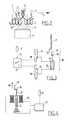
- Fig. 1 shows a device 1 for the removal of individual covers 3 from a continuous flow 2 of covers 3 each, as shown in fig. 2, comprising a middle portion 4 and a peripheral edge 5 extending asymmetrically around it in relation to the main plane thereof, the main planes of which covers extend perpendicularly to the conveying direction 6, while the nominal orientations of the covers 3 in the conveying direction 6 are all the same, and the said individual covers are oppositely oriented in relation to the nominal orientation and designated by the reference 3′.
- the device 1 comprises a conveyor with a wire gutter 7 for transporting the covers 3, 3′ by undrawn means in a continuous flow such that they press against each other; a detector 8 placed adjacent to the wire gutter for determining the possible presence of an oppositely oriented cover 3′; and an ejector 9 to remove from the flow 2 an oppositely oriented cover 3′ observed by the detector 8.
- the peripheral edges 5 of the correctly oriented covers 3 together define a substantially unbroken peripheral surface of the flow 2.
- the peripheral surface of the flow 2 is interrupted. This interruption is designated in fig. 2 by 10.
- the detector 8 arranged along the path of the flow 2 is of the type that is capable of generating a signal as soon as an interruption 10 passes.
- the covers 3, 3′ are of tin and the detector 8 produces a magnetic field drawn very schematically and indicated by 11.
- the plunger 17 When the pneumatic cylinder 16 is actuated the plunger 17 is pushed upward at great speed taking with it a block 18 which carries on one side an ejector plate 19 for ejecting a cover 3′in the direction of arrow 20, and which carries on the other side a pin 21, which co-acts with an opening 22 in a supporting frame 23 for holding the ejector plate 19 in the correct position.
- the supporting frame 23 carries the pneumatic cylinder 16 and the detector 8.
- the detector 8 and the ejector plate 19 are situated on the same axial position of the flow of covers 2. Immediately a detection signal is generated by the detector 8 energizing of the pneumatic cylinder 16 and ejection of the relevant cover therefore take place.
- Fig. 4 shows a variant in which the control unit 13 is arranged for generating a strong pulsating current to a solenoid 24 having therein an up and downward moveable iron core 25 which can drive the ejector plate 19.
Abstract
a conveyor (7) for transporting the covers (3, 3') in a continuous flow,
a detector (8) placed adjacent to the conveyor (7) for distinguishing an oppositely oriented cover (3'), and
an ejector (9) for removing from the flow (2) a detected oppositely oriented cover (3').
Description
- The invention lies in the field of the handling of a continuous flow of covers, each comprising a middle portion and a peripheral edge extending around it asymmetrically in relation to the main plane, the main planes of which covers extend perpendicularly to the conveying direction, while the nominal orientations of the covers in the conveying direction are all the same.
- When transporting such covers in a continuous flow it is of essential importance for the processing thereof that all the covers have the same orientation. It can happen however that because of a disturbance a cover will from time to time display an opposite orientation. This can be very inconvenient for the further, particularly automatic, handling of the covers and can cause disturbances. Therefore until now the flow of covers has been visually inspected and an opposite oriented cover removed from the flow.
- The object of the invention is to have such an inspection take place automatically. For this purpose the invention provides a device for removing individual covers from a continuous flow of covers, each consisting of a middle portion and a peripheral edge extending around it asymmetrically in relation to the main plane, the main planes of which covers extend perpendicularly to the conveying direction, while the nominal orientations of the covers in the conveying direction are all the same and the said individual covers are oppositely oriented in relation to the nominal orientation, which device comprises:
a conveyor for transporting the covers in a continuous flow,
a detector placed adjacent to the conveyor for distinguishing an oppositely oriented cover,and
an ejector for removing from the flow a detected oppositely oriented cover. - After the presence of an oppositely oriented cover has been determined the ejector must be capable of ejecting with complete certainty the cover for removal. To this end use could be made of a disposition whereby the detector and the ejector have different axial positions in the conveying direction, while a register or other memory is present, the input and output of which introduce a time delay coupled with the conveyor speed such that the ejector placed downstream in relation to the detector ejects with certainty the correct, i.e. wrongly, oriented cover.
- Such a method is however not very reliable, because cover flows have an element of unpredictability. Depending on the type of cover and the spread of characteristics between individual covers and loads, the covers which for instance press against each other may display a greater or lesser resilience, with the result, certainly in the case there is a slightly greater axial distance between the detector and the ejector, that the uncertainty at the location of the ejector can be so great, that such a disposition would not be able to function at all with any reasonable degree of reliability.
- The invention therefore recommends an embodiment, in which the ejector and the detector are positioned on the same axial position on the conveyor.
- With a flow of correctly oriented covers of the defined type the peripheral surface of the flow of covers is more or less unbroken. A reliable detection criterion for the presence of a wrongly oriented cover is therefore obtained with an embodiment in which the detector is arranged to generate an eject signal to the ejector when the peripheral surface of the cover flow determined by the peripheral edges of the covers displays an interruption. For instance a light beam and a light sensitive element, such as a photocell, can be used to establish such an interruption. It has been found in practice however that such a detection lends itself less well to being used for cover flows of a varying type.
- According to the invention preference is therefore given to a variant, in which at least the edges of the covers contain metal and the detector is arranged to detect the absence of metal.
- This variant in particular can be embodied such that the detector is of the electrical and/or magnetic approach type.
- Use can be made of a detector which works on the basis of a capacitive determination, acts by means of magnetism or is based on the detuning of a tuned circuit caused by the temporary absence of metal.
- It is self-evident that the ejector must be sufficiently rapid to ensure with complete certainty that the wrongly oriented cover is ejected. The speed of the ejector is of great importance particularly in the case of great conveying speeds.
- The ejector can comprise a pneumatic drive, which is controlled electrically or also comprise an electromagnetic drive, for example a solenoid with a ferromagnetic core, which can be withdrawn inside the solenoid at great speed by transmitting a pulsating current through it. The ferromagnetic core carries an element, which exerts the ejecting force on the relevant cover.
- The invention will now be elucidated with reference to the drawing. In the drawing:
- Fig. 1 shows a perspective view of a device according to the invention;
- Fig. 2 shows the detail II-II from fig. 1;
- Fig. 3 is a diagram of an ejector with pneumatic driving; and
- Fig. 4 is a diagram of an ejector with an electromagnetic driving.
- Fig. 1 shows a
device 1 for the removal of individual covers 3 from acontinuous flow 2 of covers 3 each, as shown in fig. 2, comprising a middle portion 4 and aperipheral edge 5 extending asymmetrically around it in relation to the main plane thereof, the main planes of which covers extend perpendicularly to the conveying direction 6, while the nominal orientations of thecovers 3 in the conveying direction 6 are all the same, and the said individual covers are oppositely oriented in relation to the nominal orientation and designated by thereference 3′. - The
device 1 comprises a conveyor with a wire gutter 7 for transporting thecovers detector 8 placed adjacent to the wire gutter for determining the possible presence of an oppositely orientedcover 3′; and anejector 9 to remove from theflow 2 an oppositely orientedcover 3′ observed by thedetector 8. - As fig. 2 shows, the
peripheral edges 5 of the correctlyoriented covers 3 together define a substantially unbroken peripheral surface of theflow 2. However, at the location where there is a wrongly orientedcover 3′, the peripheral surface of theflow 2 is interrupted. This interruption is designated in fig. 2 by 10. Thedetector 8 arranged along the path of theflow 2 is of the type that is capable of generating a signal as soon as aninterruption 10 passes. thecovers detector 8 produces a magnetic field drawn very schematically and indicated by 11. When the form of the peripheral surface of theflow 2 is uninterrupted this field has within certain fluctuations a constant value, but the presence of aninterruption 10 in the flow of metal covers 5 causes a disturbance of themagnetic field 11, which is observed by thedetector 8 and which causes the forming of a detection signal, which is fed via a cable 12 (see fig. 3) to acontrol unit 13, which can actuatepneumatic valves pneumatic cylinder 16 which forms part of theejector 26. When thepneumatic cylinder 16 is actuated theplunger 17 is pushed upward at great speed taking with it ablock 18 which carries on one side anejector plate 19 for ejecting acover 3′in the direction ofarrow 20, and which carries on the other side apin 21, which co-acts with an opening 22 in a supportingframe 23 for holding theejector plate 19 in the correct position. The supportingframe 23 carries thepneumatic cylinder 16 and thedetector 8. - As shown in fig. 1, the
detector 8 and theejector plate 19 are situated on the same axial position of the flow ofcovers 2. Immediately a detection signal is generated by thedetector 8 energizing of thepneumatic cylinder 16 and ejection of the relevant cover therefore take place. - Fig. 4 shows a variant in which the
control unit 13 is arranged for generating a strong pulsating current to asolenoid 24 having therein an up and downwardmoveable iron core 25 which can drive theejector plate 19.
Claims (7)
a conveyor for transporting said covers in a continuous flow,
a detector placed adjacent to said conveyor for distinguishing an oppositely oriented cover, and
an ejector for the removal from the flow of a detected oppositely oriented cover.
Priority Applications (1)
| Application Number | Priority Date | Filing Date | Title |
|---|---|---|---|
| AT89202217T ATE82213T1 (en) | 1989-06-27 | 1989-08-31 | DEVICE FOR EJECTING INCORRECTLY ORIENTED COVERS FROM A CONTINUOUS STREAM. |
Applications Claiming Priority (2)
| Application Number | Priority Date | Filing Date | Title |
|---|---|---|---|
| NL8901626 | 1989-06-27 | ||
| NL8901626A NL8901626A (en) | 1989-06-27 | 1989-06-27 | Apparatus for ejecting wrongly oriented lids from a continuous stream. |
Publications (2)
| Publication Number | Publication Date |
|---|---|
| EP0405017A1 true EP0405017A1 (en) | 1991-01-02 |
| EP0405017B1 EP0405017B1 (en) | 1992-11-11 |
Family
ID=19854913
Family Applications (1)
| Application Number | Title | Priority Date | Filing Date |
|---|---|---|---|
| EP89202217A Expired - Lifetime EP0405017B1 (en) | 1989-06-27 | 1989-08-31 | Device for ejecting wrongly oriented covers from a continuous flow |
Country Status (7)
| Country | Link |
|---|---|
| US (1) | US4977998A (en) |
| EP (1) | EP0405017B1 (en) |
| AT (1) | ATE82213T1 (en) |
| DE (1) | DE68903498T2 (en) |
| ES (1) | ES2035537T3 (en) |
| GR (1) | GR3006541T3 (en) |
| NL (1) | NL8901626A (en) |
Cited By (2)
| Publication number | Priority date | Publication date | Assignee | Title |
|---|---|---|---|---|
| EP0782888A2 (en) * | 1995-01-05 | 1997-07-09 | Mauro Lenzi | Device for automatically removing wrongly oriented elements from a supply line of caps, plugs or generally concave elements |
| EP3035060A1 (en) * | 2014-12-18 | 2016-06-22 | F. Hoffmann-La Roche AG | Method and device for handling a closing element in a laboratory automation system |
Families Citing this family (8)
| Publication number | Priority date | Publication date | Assignee | Title |
|---|---|---|---|---|
| US5145050A (en) * | 1991-12-20 | 1992-09-08 | Reynolds Metals Company | Reversed can end ejection system |
| US5226518A (en) * | 1992-01-06 | 1993-07-13 | Ball Corporation | Method and apparatus for removing inverted container ends from a moving stick |
| US5769202A (en) * | 1994-09-20 | 1998-06-23 | Mitsubishi Materials Corporation | Inside-out can lid removal device |
| US5701432A (en) * | 1995-10-13 | 1997-12-23 | Sun Microsystems, Inc. | Multi-threaded processing system having a cache that is commonly accessible to each thread |
| US6062395A (en) * | 1998-09-25 | 2000-05-16 | Metal Container Corporation | Reversed container end ejection system |
| US6257824B1 (en) * | 1999-10-05 | 2001-07-10 | Visteon Global Technologies, Inc. | Fin alternating and delivering apparatus |
| US7331443B2 (en) * | 2004-04-22 | 2008-02-19 | Amcor Limited | Vertical parallel transportation of caps |
| US7699157B2 (en) * | 2007-05-25 | 2010-04-20 | Rockwell Automation Limited | Safety arrangement |
Citations (3)
| Publication number | Priority date | Publication date | Assignee | Title |
|---|---|---|---|---|
| FR2313721A1 (en) * | 1975-06-06 | 1976-12-31 | Laurel Bank Machine Co | COIN STACK EVALUATION SYSTEM |
| US4655350A (en) * | 1985-06-26 | 1987-04-07 | Fleetwood Systems, Inc. | Reversed end ejector system |
| EP0276499A1 (en) * | 1987-01-26 | 1988-08-03 | Thomassen & Drijver-Verblifa N.V. | Device for forming a batch consisting of a predetermined number of discs |
Family Cites Families (2)
| Publication number | Priority date | Publication date | Assignee | Title |
|---|---|---|---|---|
| US3690487A (en) * | 1971-05-28 | 1972-09-12 | Mark Products | Orienting apparatus |
| US3710922A (en) * | 1971-07-06 | 1973-01-16 | Lipe Rollway Corp | Apparatus for detecting and rejecting improperly oriented objects |
-
1989
- 1989-06-27 NL NL8901626A patent/NL8901626A/en not_active Application Discontinuation
- 1989-08-31 DE DE8989202217T patent/DE68903498T2/en not_active Expired - Lifetime
- 1989-08-31 ES ES198989202217T patent/ES2035537T3/en not_active Expired - Lifetime
- 1989-08-31 EP EP89202217A patent/EP0405017B1/en not_active Expired - Lifetime
- 1989-08-31 AT AT89202217T patent/ATE82213T1/en not_active IP Right Cessation
- 1989-10-18 US US07/423,957 patent/US4977998A/en not_active Expired - Fee Related
-
1992
- 1992-12-14 GR GR920402915T patent/GR3006541T3/el unknown
Patent Citations (3)
| Publication number | Priority date | Publication date | Assignee | Title |
|---|---|---|---|---|
| FR2313721A1 (en) * | 1975-06-06 | 1976-12-31 | Laurel Bank Machine Co | COIN STACK EVALUATION SYSTEM |
| US4655350A (en) * | 1985-06-26 | 1987-04-07 | Fleetwood Systems, Inc. | Reversed end ejector system |
| EP0276499A1 (en) * | 1987-01-26 | 1988-08-03 | Thomassen & Drijver-Verblifa N.V. | Device for forming a batch consisting of a predetermined number of discs |
Cited By (7)
| Publication number | Priority date | Publication date | Assignee | Title |
|---|---|---|---|---|
| EP0782888A2 (en) * | 1995-01-05 | 1997-07-09 | Mauro Lenzi | Device for automatically removing wrongly oriented elements from a supply line of caps, plugs or generally concave elements |
| EP0782888A3 (en) * | 1995-01-05 | 1998-03-04 | Mauro Lenzi | Device for automatically removing wrongly oriented elements from a supply line of caps, plugs or generally concave elements |
| EP3035060A1 (en) * | 2014-12-18 | 2016-06-22 | F. Hoffmann-La Roche AG | Method and device for handling a closing element in a laboratory automation system |
| JP2016118544A (en) * | 2014-12-18 | 2016-06-30 | エフ.ホフマン−ラ ロシュ アーゲーF. Hoffmann−La Roche Aktiengesellschaft | Method and device for handling closing element in laboratory automation system |
| CN105807075A (en) * | 2014-12-18 | 2016-07-27 | 豪夫迈·罗氏有限公司 | Method and device for handling closing element in a laboratory automation system |
| US9810651B2 (en) | 2014-12-18 | 2017-11-07 | Roche Diagnostics Operations, Inc. | Method and device for handling a closing element in a laboratory automation system |
| CN105807075B (en) * | 2014-12-18 | 2018-03-20 | 豪夫迈·罗氏有限公司 | The method and apparatus that closure elements are handled in laboratory automation system |
Also Published As
| Publication number | Publication date |
|---|---|
| ATE82213T1 (en) | 1992-11-15 |
| DE68903498D1 (en) | 1992-12-17 |
| NL8901626A (en) | 1991-01-16 |
| EP0405017B1 (en) | 1992-11-11 |
| DE68903498T2 (en) | 1993-04-15 |
| US4977998A (en) | 1990-12-18 |
| ES2035537T3 (en) | 1993-04-16 |
| GR3006541T3 (en) | 1993-06-30 |
Similar Documents
| Publication | Publication Date | Title |
|---|---|---|
| US4883264A (en) | Bill disbursing system | |
| EP0405017A1 (en) | Device for ejecting wrongly oriented covers from a continuous flow | |
| KR970042167A (en) | Part Direction Feeder | |
| US20100224537A1 (en) | Method and Apparatus for Sorting Metal | |
| JPH05504750A (en) | document sorting device | |
| US5871078A (en) | Automatic infeeder device with reject | |
| KR880009320A (en) | Securities Processing System | |
| US6761352B2 (en) | Method and system for double feed detection | |
| US5829600A (en) | Method and apparatus for identifying different, elongated metallic objects | |
| EP0295862A2 (en) | Coin processing apparatus | |
| US20020033884A1 (en) | Machine vision-based sorter verification | |
| US5052875A (en) | Automated envelope handling system | |
| US4819783A (en) | Automated inspection system and method | |
| CA1122669A (en) | Magnetic detector | |
| US3351075A (en) | Coin-sorting and counting machine | |
| US4384202A (en) | Track controller for a document processor | |
| US4256297A (en) | Hopper | |
| US3450259A (en) | Automatic classifying device | |
| WO1994004997A1 (en) | Coin transporting apparatus and coin validation apparatus employing same | |
| JPS62285813A (en) | Longitudinal crack detecting device for conveyer belt | |
| WO1992001617A1 (en) | Magnetic trap assembly | |
| EP3040131B1 (en) | Method and device for automatically sorting articles | |
| DE19628733B4 (en) | Method and device for storage and order picking of general cargo | |
| WO1987001976A1 (en) | Optical discrimination method for component orientation | |
| US6027113A (en) | Multiple document detection system |
Legal Events
| Date | Code | Title | Description |
|---|---|---|---|
| PUAI | Public reference made under article 153(3) epc to a published international application that has entered the european phase |
Free format text: ORIGINAL CODE: 0009012 |
|
| AK | Designated contracting states |
Kind code of ref document: A1 Designated state(s): AT BE CH DE ES FR GB GR IT LI LU NL SE |
|
| 17P | Request for examination filed |
Effective date: 19910703 |
|
| R17P | Request for examination filed (corrected) |
Effective date: 19910702 |
|
| 17Q | First examination report despatched |
Effective date: 19911121 |
|
| ITF | It: translation for a ep patent filed |
Owner name: STUDIO INGG. FISCHETTI & WEBER |
|
| GRAA | (expected) grant |
Free format text: ORIGINAL CODE: 0009210 |
|
| AK | Designated contracting states |
Kind code of ref document: B1 Designated state(s): AT BE CH DE ES FR GB GR IT LI LU NL SE |
|
| REF | Corresponds to: |
Ref document number: 82213 Country of ref document: AT Date of ref document: 19921115 Kind code of ref document: T |
|
| REF | Corresponds to: |
Ref document number: 68903498 Country of ref document: DE Date of ref document: 19921217 |
|
| ET | Fr: translation filed | ||
| REG | Reference to a national code |
Ref country code: ES Ref legal event code: FG2A Ref document number: 2035537 Country of ref document: ES Kind code of ref document: T3 |
|
| REG | Reference to a national code |
Ref country code: GR Ref legal event code: FG4A Free format text: 3006541 |
|
| PLBE | No opposition filed within time limit |
Free format text: ORIGINAL CODE: 0009261 |
|
| STAA | Information on the status of an ep patent application or granted ep patent |
Free format text: STATUS: NO OPPOSITION FILED WITHIN TIME LIMIT |
|
| 26N | No opposition filed | ||
| EPTA | Lu: last paid annual fee | ||
| EAL | Se: european patent in force in sweden |
Ref document number: 89202217.9 |
|
| PGFP | Annual fee paid to national office [announced via postgrant information from national office to epo] |
Ref country code: BE Payment date: 19950208 Year of fee payment: 6 |
|
| PGFP | Annual fee paid to national office [announced via postgrant information from national office to epo] |
Ref country code: SE Payment date: 19950210 Year of fee payment: 6 Ref country code: CH Payment date: 19950210 Year of fee payment: 6 |
|
| PGFP | Annual fee paid to national office [announced via postgrant information from national office to epo] |
Ref country code: GR Payment date: 19950214 Year of fee payment: 6 Ref country code: AT Payment date: 19950214 Year of fee payment: 6 |
|
| PGFP | Annual fee paid to national office [announced via postgrant information from national office to epo] |
Ref country code: LU Payment date: 19950301 Year of fee payment: 6 |
|
| PGFP | Annual fee paid to national office [announced via postgrant information from national office to epo] |
Ref country code: FR Payment date: 19950830 Year of fee payment: 7 |
|
| PG25 | Lapsed in a contracting state [announced via postgrant information from national office to epo] |
Ref country code: LU Free format text: LAPSE BECAUSE OF NON-PAYMENT OF DUE FEES Effective date: 19950831 Ref country code: LI Effective date: 19950831 Ref country code: CH Effective date: 19950831 Ref country code: BE Effective date: 19950831 Ref country code: AT Effective date: 19950831 |
|
| PGFP | Annual fee paid to national office [announced via postgrant information from national office to epo] |
Ref country code: NL Payment date: 19950831 Year of fee payment: 7 Ref country code: ES Payment date: 19950831 Year of fee payment: 7 Ref country code: DE Payment date: 19950831 Year of fee payment: 7 |
|
| PG25 | Lapsed in a contracting state [announced via postgrant information from national office to epo] |
Ref country code: SE Effective date: 19950901 |
|
| PGFP | Annual fee paid to national office [announced via postgrant information from national office to epo] |
Ref country code: GB Payment date: 19950904 Year of fee payment: 7 |
|
| PG25 | Lapsed in a contracting state [announced via postgrant information from national office to epo] |
Ref country code: GR Free format text: THE PATENT HAS BEEN ANNULLED BY A DECISION OF A NATIONAL AUTHORITY Effective date: 19960228 |
|
| BERE | Be: lapsed |
Owner name: MACHINEFABRIEK CSW B.V. Effective date: 19950831 |
|
| REG | Reference to a national code |
Ref country code: CH Ref legal event code: PL |
|
| REG | Reference to a national code |
Ref country code: GR Ref legal event code: MM2A Free format text: 3006541 |
|
| EUG | Se: european patent has lapsed |
Ref document number: 89202217.9 |
|
| PG25 | Lapsed in a contracting state [announced via postgrant information from national office to epo] |
Ref country code: GB Effective date: 19960831 |
|
| PG25 | Lapsed in a contracting state [announced via postgrant information from national office to epo] |
Ref country code: ES Free format text: LAPSE BECAUSE OF EXPIRATION OF PROTECTION Effective date: 19960902 |
|
| PG25 | Lapsed in a contracting state [announced via postgrant information from national office to epo] |
Ref country code: NL Effective date: 19970301 |
|
| GBPC | Gb: european patent ceased through non-payment of renewal fee |
Effective date: 19960831 |
|
| PG25 | Lapsed in a contracting state [announced via postgrant information from national office to epo] |
Ref country code: FR Effective date: 19970430 |
|
| NLV4 | Nl: lapsed or anulled due to non-payment of the annual fee |
Effective date: 19970301 |
|
| PG25 | Lapsed in a contracting state [announced via postgrant information from national office to epo] |
Ref country code: DE Effective date: 19970501 |
|
| REG | Reference to a national code |
Ref country code: FR Ref legal event code: ST |
|
| REG | Reference to a national code |
Ref country code: ES Ref legal event code: FD2A Effective date: 19990601 |
|
| PG25 | Lapsed in a contracting state [announced via postgrant information from national office to epo] |
Ref country code: IT Free format text: LAPSE BECAUSE OF NON-PAYMENT OF DUE FEES;WARNING: LAPSES OF ITALIAN PATENTS WITH EFFECTIVE DATE BEFORE 2007 MAY HAVE OCCURRED AT ANY TIME BEFORE 2007. THE CORRECT EFFECTIVE DATE MAY BE DIFFERENT FROM THE ONE RECORDED. Effective date: 20050831 |