EP0405452A2 - Gas flow type angular velocity sensor - Google Patents
Gas flow type angular velocity sensor Download PDFInfo
- Publication number
- EP0405452A2 EP0405452A2 EP90112140A EP90112140A EP0405452A2 EP 0405452 A2 EP0405452 A2 EP 0405452A2 EP 90112140 A EP90112140 A EP 90112140A EP 90112140 A EP90112140 A EP 90112140A EP 0405452 A2 EP0405452 A2 EP 0405452A2
- Authority
- EP
- European Patent Office
- Prior art keywords
- angular velocity
- gas flow
- heat wires
- gas
- flow type
- Prior art date
- Legal status (The legal status is an assumption and is not a legal conclusion. Google has not performed a legal analysis and makes no representation as to the accuracy of the status listed.)
- Granted
Links
Images


Classifications
-
- G—PHYSICS
- G01—MEASURING; TESTING
- G01C—MEASURING DISTANCES, LEVELS OR BEARINGS; SURVEYING; NAVIGATION; GYROSCOPIC INSTRUMENTS; PHOTOGRAMMETRY OR VIDEOGRAMMETRY
- G01C19/00—Gyroscopes; Turn-sensitive devices using vibrating masses; Turn-sensitive devices without moving masses; Measuring angular rate using gyroscopic effects
- G01C19/58—Turn-sensitive devices without moving masses
Definitions
- the present invention relates to a gas flow type angular velocity sensor which is capable of sensing an angular velocity acting on the sensor's body.
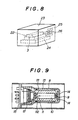
- a gas flow type angular velocity sensor is constructed in such a way that a gas is forced into a gas path 10 in a closed casing 8 through a nozzle hole 9 to flow therealong toward a flow sensor 11 consisting of a pair of heat wires as shown in Fig. 9, and, when an angular velocity " ⁇ " is applied on the sensor body, the gas flow is deflected to one side by a value of deflection " ⁇ " from an axis 0-0 as shown in FIg.
- the heat wires 111, 112 are arranged opposite to each other at both sides of the line 0-0 passing through centres of the nozzle hole 9 and the gas path 10. While no lateral angular velocity " ⁇ " acts on the sensor body, gas injected through the nozzle hole 9 flows straight along the line 0-0 and evenly attacks the wires 111 and 112 to give out equal quantities of radiated heat to them.
- At least two flow-rectifying holes 14 are arranged at opposite sides along the axis of the nozzle hole 9 so as to rectify a flow of gas injected into a gas path 10 through a nozzle hole 9.
- the heat wires 111 and 112 are usually formed to be of about 5 ⁇ m in diameter.
- each of the heat wires 111 and 112 is formed as a fine filament and then stretched between two supporting electrodes 17 mounted on a base plate 16 as shown in Fig. 11.
- the process for finely preforming the heat wires 111 and 12 may induce a change in the material composition, crystal structure and resistance-temperature characteristic of the wires.
- the heat wires 111 and 112 and the supporting electrodes are previously plated with gold and then attached to each other by use of gold bonding means.
- the heat wires 111 and 112 thus attached to the supporting electrodes have such a disadvantage that their detection sensitivity drops due to gold plating and their detection accuracy is also lowered due to thermoelectromotive force caused between dissimilar metals.
- the heat wires 111 and 112 attached by gold bonding means to the supporting electrodes are usually subjected to further annealing by heating in vacuum or inert gas to stabilize the metal structure of the heat wires through recrystallization and also to vaporize the gold from the wire surfaces.
- the conventional gas flow type angular velocity sensor is provided at one end of its casing 8 with a diaphragm pump 12 whereby gas filled in the closed casing 8 is circulated in such a way that it flows through a path 13 and then through a nozzle hole 9 enters into a gas path 10 to create therein a laminar flow.
- the pump would be made with an insufficient accuracy and therefore would work unsteady, it could not create a stabilized gas flow in the sensor's casing, resulting in lowering the detection accuracy of the sensor.
- a circuit board 15, whereon amplifier circuit and all portion of the resistance bridge circuit excepting the paired heat wires are mounted is attached to one end of the casing 8 as separated from sensor body.
- the conventional sensor may produce an error output with no angular velocity and therefore be adjusted to cut off the error output value. Furthermore, since the off-set value may be also changed depending on a change of gas temperature, the sensor body is usually placed in a thermostat.
- the circuit board having the above-mentioned circuits' components thereon is also placed in the thermostat so as to suppress a temperature drift, but, in the strict sense, the board and the paired heat wires are not placed in the same temperature medium and therefore the temperature drift due to a difference in their temperature conditions may arise to induce a noise into the sensor's output.
- the present invention was made to provide a gas flow type angular velocity sensor which is so constructed that nozzle holes and gas path may be easily formed therein with a high accuracy of their finishing.
- the present invention is directed to form a nozzle hole and a gas path by etching semiconductor substrates by use of a semiconductor technology.
- This invention is also directed to form a pair of heat wires serving as a flow sensor by etching a heat wire metal previously deposited in vacuum on the semiconductor substrate by use of the semiconductor technology.
- This invention is also directed to densely (with a high degree of integration) form by use of an IC technology a miniature pump to be driven by a piezoelectric element on the semiconductor substrates with the gas path formed thereon.
- This invention furthermore attempts to densely form by utilizing the IC technology a resistance bridge circuit and an amplifier circuit on a semiconductor substrate with the gas path formed thereon.
- a gas flow type angular velocity sensor is composed of an upper and a lower semiconductor substrates 1 and 2, each of which a half-hole 31 composing a nozzle hole 3 and a half-groove 41 composing a gas path 4 are formed on by etching method, and both of which are laid on and adhered to each other to form a nozzle 3 and a gas path 4 therein.
- etching technique for manufacturing semiconductors can easily and precisely make the nozzle holes 3 and the gas paths 4 on semiconductor substrates with accuracies of submicron order and in a large quantity.
- the present invention makes it possible to easily produce a large quantity of the sensors of uniform quality with a high yield.
- the senor is capable of injecting gas into the gas path 4 through the nozzle hole 3 to create a gas flow going straight along the axis 0-0 of the gas path while no angular velocity being applied to the sensor body. This improves the detection accuracy of the sensor.
- the nozzle hole 3 and the gas path 4 can be precisely made in a very small size, it is possible to realize miniaturization of the gas flow type angular velocity sensor.
- the present invention provides that a bridge portion 6 is formed over the half-groove composing the gas path 4 on the lower semiconductor substrate by etching method and then a pair of heat wires 451 and 52 are formed on said bridge portion 6.
- the bridge portion 6 is provided at the height corresponding to a substantially middle height of the gas path 4.
- the paired heat wires 51 and 52 are formed according to a given pattern by etching and trimming the tungsten or platinum material previously deposited on the upper surface of the bridge portion 6 by evaporating or crystal growing method.
- each of heat wires 51 and 52 may be formed of such a pattern that a total length of each wire is sufficient to detect the gas flow with a high sensitivity.
- Fig. 5 shows another example of a pattern of the paired heat wires 51 and 52.
- Electrodes 7 for connection with the heat wires 51 and 52 are formed in such a process that material of the same kind as that of the heat wires 51 and 52 is deposited by evaporation on given portions adjoining the both ends of the bridge portion 6 on semiconductor substrate 1 and then a given pattern of each electrode is etched on a given portion and finished by trimming.
- the heat wires 51 and 52 can be precisely formed in a simultaneous process applying the semiconductor technology, it is assured to easily make a large quantity of the paired heat wires being free from variations in their material composition, crystal structure and resistance-temperature characteristic.
- the heat wires 51 and 52 and electrodes 7 can be integrally made with each other of the same kind of metal, the necessity of gold bonding means for connecting heat wires with electrodes as seen in the prior art is omitted, thereby the possibilities of lowering detection sensitivity of the heat wires due to the existence of dissimilar metal such as gold or the like and also of decreasing its detection accuracy due to thermoelectromotive force produced by the dissimilar metal are eliminated.
- the present invention provides that a miniature pump 18 to be driven by a piezoelectric element is formed densely at an inner downstream part from the heat wires 51, 52 in the gas path 4 on the lower semiconductor substrate 1.
- Fig. 6 shows a typical construction of miniature pump 18.
- a diaphragm 182 drivable by a piezoelectric element 181 is formed by etching the semiconductor (Si) substrate 1a.
- a pumping chamber 183 is formed by placing a semiconductor substrate 1b on the semiconductor substrate 1a.
- a suction port 184 and a delivery port 185 are also formed by etching the substrate 1b.
- a suction valve 186 and a delivery valve 187 are formed in the suction port 184 and the delivery port 185 respectively.
- the miniature pump is formed densely by use of the IC technology on the portion of the semiconductor substrate 1 whereon the gas path is formed, it is possible to incorporate the precision miniature pump in sensor body.
- the miniature pump 18 can effectively create a stabilized gas flow that makes it possible to accurately detect an angular velocity acting on the sensor body.
- the present invention is directed to provide integrated circuits 19 and 20 respectively at the opposite sides of a half-groove 41 for forming gas path 4 on the semiconductor substrate 1.
- Each of the integrated circuits 19 and 20 includes densely a part of a resistance bridge circuit (excepting a heat wire 51 or 52) for detecting an angular velocity and also an amplifier circuit for amplifying the detection signal from the resistance bridge circuit.
- external connection terminals 21 formed together with the integrated circuits 19 and 20 are used as terminals for connection with a power supply source for the resistance bridge circuit or for wiring for outputting the angular velocity detection signal from the amplifier circuit.
- the resistance bridge circuit and the amplifier circuit are formed densely on the semiconductor substrate with the gas path formed thereon, it is possible to incorporate the above-mentioned circuits in the sensor body with a high space factor and in an optimum position assuring no interference with angular velocity detection.
- two standard resistances can be formed by use of the IC technology to be of a correct resistance for two respective branch lines of the resistance bridge circuit.
- These standard resistances can be also arranged in positions free from affection of the gas flow.
- the present invention requires no connections between the above-mentioned components and the circuits and thereby completely eliminates the possibility to cause a contact resistance at the lead-wire connections and thermoelectromotive force at the dissimilar metals' junctions. The accuracy of angular velocity detection is therefore improved.
- the paired heat wires 51, 52 provided on the gas path 4 and other component parts of the resistance bridge circuit and the amplifier circuit are placed under the same temperature condition and thereby the possibility to induce a noise due to a temperature drift in the circuits can be effectively reduced.
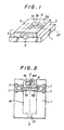
- Fig. 8 shows a working state of an angular velocity sensor according to the present invention.
- a sensor body 22 which consists of an upper and a lower semiconductor substrates having therein a nozzle hole 3, a gas path 4 with a pair of heat wires 51 and 52 and incorporates a miniature pump 18 in the inner part thereof, is placed on a base 24 in a gas-filled case 23 and is put into working state by driving the pump to force the gas into the gas path 4 of the sensor body through the nozzle hole 3 creating gas circulation in the case 23.
- power supply terminals and output terminals are designated with numerals 25 and 26 respectively.
- the present invention provides to form the nozzle hole and the gas path in such a way that upper halves and lower halves of a nozzle hole and a gas path are etched on an upper and a lower semiconductor substrates and be placed on each other the upper and lower semiconductor substrates to match the halves of holes and grooves, thereby providing such advantages that the nozzle hole and the gas path can be easily formed with a high accuracy and the mass-productivity of the sensor is much improved.
- An advantage of the gas flow type angular velocity sensor according to the present invention consists in that since a pair of heat wires are made by etching their materials previously deposited on the upper or the lower semiconductor substrate, the paired heat wires having the stabilized material composition and crystal structure and the uniform resistance temperature characteristic can be easily and effectively formed in the sensor that makes the later adequate for mass production.
- gas flow type angular velocity sensor Another advantage of the gas flow type angular velocity sensor according to the present invention exists in that since miniature pump drivable by a piezoelectric element is formed densely on the semiconductor substrate within the gas path, it is possible to create a stabilized gas flow in the sensor at a high efficiency by use of the precisely formed miniature pump which can be incorporated in an optimum state in the sensor body.
- gas flow type angular velocity sensor consists in that since in addition to forming the gas path by etching the semiconductor substrates a resistance bridge circuit consisting of a paired heat wires and resistances having a known resistance value for detecting an angular velocity and an amplifier circuit for amplifying a detection signal from the resistance bridge circuit are formed densely on the same semiconductor substrates, all circuit components can be best arranged in the sensor body with a high space factor and with no interference with angular velocity detection, thereby the disadvantages of the prior art such as the occurrence of contact resistance through lead-wire connections and of thermoelectromotive force through dissimilar metals' junctions are eliminated, and all circuit components can be placed under the same temperature condition, thereby the occurrence of noise due to a temperature drift is effectively reduced and the detection accuracy is improved.
- a gas flow type angular velocity sensor comprising two semiconductor substrates with all components formed thereon by use of a semiconductor technology and an IC technology, which are coupled with each other to form therein a pair of heat wires, a gas path and a nozzle holes for injecting a gas flow toward the paired heat wires in the gas path.
- Two heat wires of the pair changes their resistance-temperature characteristics in accordance with a deflection of the gas flow due to the action of angular velocity and a difference between two changed values is picked up and amplified by a resistance bridge circuit and an amplifier circuit formed on the semiconductor substrates to produce an output signal proportional to the angular velocity to be measured.
- a miniature pump formed on semiconductor substrates and drivable by a piezoelectric element provides a stabilized gas flow in the sensor.
Abstract
Description
- The present invention relates to a gas flow type angular velocity sensor which is capable of sensing an angular velocity acting on the sensor's body.
- Generally, a gas flow type angular velocity sensor is constructed in such a way that a gas is forced into a
gas path 10 in a closedcasing 8 through anozzle hole 9 to flow therealong toward aflow sensor 11 consisting of a pair of heat wires as shown in Fig. 9, and, when an angular velocity "ω" is applied on the sensor body, the gas flow is deflected to one side by a value of deflection "ε" from an axis 0-0 as shown in FIg. 10 to produce a difference between temperature sensitive outputs of twoheat wires - The
heat wires nozzle hole 9 and thegas path 10. While no lateral angular velocity "ω" acts on the sensor body, gas injected through thenozzle hole 9 flows straight along the line 0-0 and evenly attacks thewires - Consequently, it becomes possible to measure a value of change in moving direction of a moving body when the latter is equipped with such a gas flow type angular velocity sensor.
- In Fig. 9, at least two flow-rectifying
holes 14 are arranged at opposite sides along the axis of thenozzle hole 9 so as to rectify a flow of gas injected into agas path 10 through anozzle hole 9. - Thus constructed gas flow type angular velocity sensor, since its detecting accuracy depends upon the accuracy of finishing its components, must have the precisely formed
nozzle hole 9 andgas path 10 so that gas forced into thegas path 10 through thenozzle hole 9 may flow straight along a center line 0-0 while no lateral angular velocity "ω" acts on the sensor body. - In a conventional gas flow type angular velocity sensor its
nozzle hole 9 andgas path 10 are formed by cutting aluminium tubes. - However, since said method for making the
nozzle hole 9 and thegas path 10 requires a high technique of precision working, the components are produced with poor yield and with wide variations in their quality and therefore are hardly adequate for mass production. - In the gas flow type angular velocity sensor, since the
finer heat wires sensor 11 is obtained, i.e. less displacement of the gas flow can be detected, theheat wires - Usually, each of the
heat wires electrodes 17 mounted on abase plate 16 as shown in Fig. 11. - However, the process for finely preforming the
heat wires - Accordingly, it is hardly difficult to make a pair of
heat wires - Furthermore, when the
heat wires electrodes 17 are heated by electric current, there arises such a problem that the heat wires are subjected to heat stress aging, resulting in change of their resistance-temperature characteristic. - In the prior art, the
heat wires - The
heat wires - Accordingly, the
heat wires - As shown in Fig. 9, the conventional gas flow type angular velocity sensor is provided at one end of its
casing 8 with adiaphragm pump 12 whereby gas filled in the closedcasing 8 is circulated in such a way that it flows through apath 13 and then through anozzle hole 9 enters into agas path 10 to create therein a laminar flow. - Thus constructed sensor, since the
pump 12 mounted therein has a large size, is also large in its size. - If the pump would be made with an insufficient accuracy and therefore would work unsteady, it could not create a stabilized gas flow in the sensor's casing, resulting in lowering the detection accuracy of the sensor.
- Furthermore, in the conventional gas flow type angular velocity sensor shown in Fig. 9, a
circuit board 15, whereon amplifier circuit and all portion of the resistance bridge circuit excepting the paired heat wires are mounted, is attached to one end of thecasing 8 as separated from sensor body. In this case it is needed to make soldered lead-wire connections between the paired heat wires in the in the sensor body and corresponding terminals on thecircuit board 15, whereby a contact resistance at the connections and thermoelectromotive force due to dissimilar metals' junction are irrevocably caused and correspondingly the accuracy of angular velocity measurement drops. - Since the paired heat wires differ in their resistance-temperature characteristics, the conventional sensor may produce an error output with no angular velocity and therefore be adjusted to cut off the error output value. Furthermore, since the off-set value may be also changed depending on a change of gas temperature, the sensor body is usually placed in a thermostat.
- In this case the circuit board having the above-mentioned circuits' components thereon is also placed in the thermostat so as to suppress a temperature drift, but, in the strict sense, the board and the paired heat wires are not placed in the same temperature medium and therefore the temperature drift due to a difference in their temperature conditions may arise to induce a noise into the sensor's output.
- In view of the foregoing, the present invention was made to provide a gas flow type angular velocity sensor which is so constructed that nozzle holes and gas path may be easily formed therein with a high accuracy of their finishing.
- It is another object of the invention to provide a gas flow type angular velocity sensor which permits easy forming therein a pair of heat wires having the stabilized material composition and the uniform resistance-temperature characteristic with no need for after-treatment such as annealing or the like.
- It is another object of the invention to provide a a gas flow type angular velocity sensor which is capable of effectively creating a stabilized gas flow therein by incorporating a small precision type pump in an optimum condition in the sensor body.
- It is further object of the invention to provide a gas flow type angular velocity sensor which can accommodate a resistance bridge circuit composed of a pair of heat wires and known standard resistances for detecting an angular velocity and also an amplifier circuit for amplifying the detection signal in its body with an effective space factor and in an optimum condition assuring no interference to the angular velocity detection, thereby eliminating the above-mentioned prior art's disadvantages concerning the lead-wire connections and the temperature drift to induce a noise.
-
- Fig. 1 is a perspective view showing a body portion of a gas flow type angular velocity sensor embodying the present invention.
- Fig. 2 is a plan view showing an example of construction of a lower semiconductor substrate of the sensor body.
- Fig. 3 is a partial perspective view of the lower semiconductor substrate.
- Fig. 4 is a sectional view taken along line A-A of Fig. 1.
- Fig. 5 is a view showing another example of a pattern of heat wires.
- Fig. 6 is a front sectional view showing an example of a construction of a miniature pump.
- Fig. 7 is a plan view showing another example of a construction of the lower semiconductor substrate.
- Fig. 8 is a perspective view showing a general construction of a gas flow type angular velocity sensor according to the present invention.
- Fig. 9 is a front sectional view showing a conventional gas flow type angular velocity sensor.
- Fig. 10 is a view showing a deflected gas flow when an angular velocity is applied to a gas flow type angular velocity sensor.
- Fig. 11 is a perspective view showing a flow sensor of a conventional gas flow type angular velocity sensor.
- In order to achieve the above-mentioned purposes, the present invention is directed to form a nozzle hole and a gas path by etching semiconductor substrates by use of a semiconductor technology.
- This invention is also directed to form a pair of heat wires serving as a flow sensor by etching a heat wire metal previously deposited in vacuum on the semiconductor substrate by use of the semiconductor technology.
- This invention is also directed to densely (with a high degree of integration) form by use of an IC technology a miniature pump to be driven by a piezoelectric element on the semiconductor substrates with the gas path formed thereon.
- This invention furthermore attempts to densely form by utilizing the IC technology a resistance bridge circuit and an amplifier circuit on a semiconductor substrate with the gas path formed thereon.
- Referring now to the drawings, an embodiment of the present invention will be described in detail as follows:
- As shown in Figs. 1 - 4, a gas flow type angular velocity sensor according to the present invention is composed of an upper and a lower semiconductor substrates 1 and 2, each of which a half-
hole 31 composing anozzle hole 3 and a half-groove 41 composing agas path 4 are formed on by etching method, and both of which are laid on and adhered to each other to form anozzle 3 and agas path 4 therein. - Application of the etching technique for manufacturing semiconductors can easily and precisely make the
nozzle holes 3 and thegas paths 4 on semiconductor substrates with accuracies of submicron order and in a large quantity. - Therefore, as opposed to the prior art which is based upon individual production by skilled persons, the present invention makes it possible to easily produce a large quantity of the sensors of uniform quality with a high yield.
- Having the accurately made nozzle hole and gas path, the sensor is capable of injecting gas into the
gas path 4 through thenozzle hole 3 to create a gas flow going straight along the axis 0-0 of the gas path while no angular velocity being applied to the sensor body. This improves the detection accuracy of the sensor. - According to the present invention, since the
nozzle hole 3 and thegas path 4 can be precisely made in a very small size, it is possible to realize miniaturization of the gas flow type angular velocity sensor. - It is, of course, possible to provide a gas flow rectifying holes (see Fig. 6) at opposite sides along the
nozzle hole 3, if the rectification of the gas flow in thegas path 4 is needed, by etching half-holes composing each flow-rectifying hole together with half-holes for nozzle and the half-grooves for the gas path on the upper and the lower substrates. - In case of forming the above-mentioned flow-rectifying holes together with the nozzle hole and the gas path all of them can be made uniformly with high accuracies of their positions and sizes.
- The present invention provides that a
bridge portion 6 is formed over the half-groove composing thegas path 4 on the lower semiconductor substrate by etching method and then a pair ofheat wires 451 and 52 are formed on saidbridge portion 6. - In the above-mentioned case the
bridge portion 6 is provided at the height corresponding to a substantially middle height of thegas path 4. - The paired
heat wires bridge portion 6 by evaporating or crystal growing method. - In this case, each of
heat wires - Fig. 5 shows another example of a pattern of the paired
heat wires -
Electrodes 7 for connection with theheat wires heat wires bridge portion 6 on semiconductor substrate 1 and then a given pattern of each electrode is etched on a given portion and finished by trimming. - According to the present invention, since the
heat wires - According to the present invention, since the
heat wires electrodes 7 can be integrally made with each other of the same kind of metal, the necessity of gold bonding means for connecting heat wires with electrodes as seen in the prior art is omitted, thereby the possibilities of lowering detection sensitivity of the heat wires due to the existence of dissimilar metal such as gold or the like and also of decreasing its detection accuracy due to thermoelectromotive force produced by the dissimilar metal are eliminated. - The present invention provides that a
miniature pump 18 to be driven by a piezoelectric element is formed densely at an inner downstream part from theheat wires gas path 4 on the lower semiconductor substrate 1. - Fig. 6 shows a typical construction of
miniature pump 18. - In Fig. 6, a
diaphragm 182 drivable by apiezoelectric element 181 is formed by etching the semiconductor (Si)substrate 1a. Apumping chamber 183 is formed by placing asemiconductor substrate 1b on thesemiconductor substrate 1a. Asuction port 184 and adelivery port 185 are also formed by etching thesubstrate 1b. Asuction valve 186 and adelivery valve 187 are formed in thesuction port 184 and thedelivery port 185 respectively. - According to the present invention, since the miniature pump is formed densely by use of the IC technology on the portion of the semiconductor substrate 1 whereon the gas path is formed, it is possible to incorporate the precision miniature pump in sensor body.
- Consequently, the
miniature pump 18 can effectively create a stabilized gas flow that makes it possible to accurately detect an angular velocity acting on the sensor body. - Therefore, it becomes also possible to easily and effectively produce the sensors of uniform quality in a large quantity.
- As shown in Fig. 7, the present invention is directed to provide
integrated circuits groove 41 for forminggas path 4 on the semiconductor substrate 1. - Each of the
integrated circuits heat wire 51 or 52) for detecting an angular velocity and also an amplifier circuit for amplifying the detection signal from the resistance bridge circuit. - At the same time, in the integrated circuit of the resistance bridge all components' parts excepting the
heat wires respective heat wires bridge 6. - In Fig. 7,
external connection terminals 21 formed together with theintegrated circuits - According to the present invention, since the resistance bridge circuit and the amplifier circuit are formed densely on the semiconductor substrate with the gas path formed thereon, it is possible to incorporate the above-mentioned circuits in the sensor body with a high space factor and in an optimum position assuring no interference with angular velocity detection.
- At the same time, two standard resistances can be formed by use of the IC technology to be of a correct resistance for two respective branch lines of the resistance bridge circuit. These standard resistances can be also arranged in positions free from affection of the gas flow.
- Accordingly, as differed from the prior art wherein the lead wire connections are made between the
heat wires - The paired
heat wires gas path 4 and other component parts of the resistance bridge circuit and the amplifier circuit are placed under the same temperature condition and thereby the possibility to induce a noise due to a temperature drift in the circuits can be effectively reduced. - Fig. 8 shows a working state of an angular velocity sensor according to the present invention.
- In this embodiment, a
sensor body 22, which consists of an upper and a lower semiconductor substrates having therein anozzle hole 3, agas path 4 with a pair ofheat wires miniature pump 18 in the inner part thereof, is placed on a base 24 in a gas-filledcase 23 and is put into working state by driving the pump to force the gas into thegas path 4 of the sensor body through thenozzle hole 3 creating gas circulation in thecase 23. - In Fig. 8, power supply terminals and output terminals are designated with
numerals - According to the present invention, since all parts of a gas flow type angular velocity sensor can be formed by utilizing the semiconductor technology and the IC technology, it becomes possible to obtain a small and precise gas flow type angular velocity sensor adequate for mass production.
- As apparent from the foregoing description, in a gas flow type angular velocity sensor wherein an output signal corresponding to a difference in temperature sensitive outputs of its paired heat wires is produced when a flow of gas injected into a gas path through a nozzle hole and directed toward the paired heat wires is deflected by the action of an angular velocity on the gas flow, the present invention provides to form the nozzle hole and the gas path in such a way that upper halves and lower halves of a nozzle hole and a gas path are etched on an upper and a lower semiconductor substrates and be placed on each other the upper and lower semiconductor substrates to match the halves of holes and grooves, thereby providing such advantages that the nozzle hole and the gas path can be easily formed with a high accuracy and the mass-productivity of the sensor is much improved.
- An advantage of the gas flow type angular velocity sensor according to the present invention consists in that since a pair of heat wires are made by etching their materials previously deposited on the upper or the lower semiconductor substrate, the paired heat wires having the stabilized material composition and crystal structure and the uniform resistance temperature characteristic can be easily and effectively formed in the sensor that makes the later adequate for mass production.
- Another advantage of the gas flow type angular velocity sensor according to the present invention exists in that since miniature pump drivable by a piezoelectric element is formed densely on the semiconductor substrate within the gas path, it is possible to create a stabilized gas flow in the sensor at a high efficiency by use of the precisely formed miniature pump which can be incorporated in an optimum state in the sensor body.
- Further advantage of the gas flow type angular velocity sensor according to the present invention consists in that since in addition to forming the gas path by etching the semiconductor substrates a resistance bridge circuit consisting of a paired heat wires and resistances having a known resistance value for detecting an angular velocity and an amplifier circuit for amplifying a detection signal from the resistance bridge circuit are formed densely on the same semiconductor substrates, all circuit components can be best arranged in the sensor body with a high space factor and with no interference with angular velocity detection, thereby the disadvantages of the prior art such as the occurrence of contact resistance through lead-wire connections and of thermoelectromotive force through dissimilar metals' junctions are eliminated, and all circuit components can be placed under the same temperature condition, thereby the occurrence of noise due to a temperature drift is effectively reduced and the detection accuracy is improved.
- A gas flow type angular velocity sensor comprising two semiconductor substrates with all components formed thereon by use of a semiconductor technology and an IC technology, which are coupled with each other to form therein a pair of heat wires, a gas path and a nozzle holes for injecting a gas flow toward the paired heat wires in the gas path. Two heat wires of the pair changes their resistance-temperature characteristics in accordance with a deflection of the gas flow due to the action of angular velocity and a difference between two changed values is picked up and amplified by a resistance bridge circuit and an amplifier circuit formed on the semiconductor substrates to produce an output signal proportional to the angular velocity to be measured. A miniature pump formed on semiconductor substrates and drivable by a piezoelectric element provides a stabilized gas flow in the sensor. Thus constructed sensor is compact, accurate and suitable for mass-production and free from disadvantages of conventional sensors.
Claims (9)
- (1) A gas flow type angular velocity sensor wherein an output corresponding to a difference in two temperature-sensitive outputs of a pair of heat wires is obtainable when a flow of gas forced into a gas path in a sensor body through a nozzle hole and directed toward the pair of heat wires being deflected by the action of an angular velocity on the gas flow, characterized in that an upper and a lower semiconductor substrates, each of which has an etched thereon half-hole composing the nozzle hole and an etched thereon half-groove composing the gas path, are placed on each other by matching the etched half-holes and half-grooves to form the nozzle hole and the gas path.
- (2) A gas flow type angular velocity sensor according to claim 1, characterized in that a pair of heat wires are made by etching their materials previously formed to the upper or the lower semiconductor substrate.
- (3) A gas flow type angular velocity sensor according to claim 2, characterized in that the materials of the paired heat wires are formed on the semiconductor substrate by vapour deposition.
- (4) A gas flow type angular velocity sensor according to claim 2, characterized in that the materials of the paired heat wires are formed on the semiconductor substrate by crystal growing.
- (5) A gas flow type angular velocity sensor according to claim 2, characterized in that a bridge portion stretching over the gas path is formed by etching the semiconductor substrate and the paired heat wires are formed on the bridge portion.
- (6) A gas flow type angular velocity sensor according to claim 2, characterized in that each of the paired wires is formed to be of a pattern having a large wire length.
- (7) A gas flow type angular velocity sensor according to claim 2, characterized in that a miniature pump drivable by a piezoelectric element is formed densely on the semi-conductor substrate within the gas path.
- (8) A gas flow type angular velocity sensor according to claim 7, characterized in that the miniature pump is formed at a downstream side from the paired heat wires in the gas path.
- (9) A gas flow type angular velocity sensor wherein resistance-temperature characteristics of two paired heat wires are changeable in accordance with a deflection of a flow of gas forced into a gas path through a nozzle hole and directed toward the paired heat wires by the action of an acting angular velocity, and a difference of the changes can be detected by a resistance bridge circuit consisting of the paired heat wires and known resistances and then be amplified by an amplifier circuit to obtain an output signal proportional to the angular velocity to be measured, characterized in that the gas path is formed by etching semiconductor substrates and the resistance bridge circuit and the amplifier circuit are also formed densely on the same semiconductor substrates.
Applications Claiming Priority (2)
| Application Number | Priority Date | Filing Date | Title |
|---|---|---|---|
| JP165762/89 | 1989-06-28 | ||
| JP1165762A JP2721840B2 (en) | 1989-06-28 | 1989-06-28 | Gas angular velocity detector |
Publications (3)
| Publication Number | Publication Date |
|---|---|
| EP0405452A2 true EP0405452A2 (en) | 1991-01-02 |
| EP0405452A3 EP0405452A3 (en) | 1991-03-27 |
| EP0405452B1 EP0405452B1 (en) | 1993-09-01 |
Family
ID=15818563
Family Applications (1)
| Application Number | Title | Priority Date | Filing Date |
|---|---|---|---|
| EP90112140A Expired - Lifetime EP0405452B1 (en) | 1989-06-28 | 1990-06-26 | Gas flow type angular velocity sensor |
Country Status (4)
| Country | Link |
|---|---|
| US (1) | US5107707A (en) |
| EP (1) | EP0405452B1 (en) |
| JP (1) | JP2721840B2 (en) |
| DE (1) | DE69003033T2 (en) |
Cited By (4)
| Publication number | Priority date | Publication date | Assignee | Title |
|---|---|---|---|---|
| EP0519404A1 (en) * | 1991-06-19 | 1992-12-23 | Honda Giken Kogyo Kabushiki Kaisha | Gas flow type angular velocity sensor |
| EP0528251A2 (en) * | 1991-08-21 | 1993-02-24 | Honda Giken Kogyo Kabushiki Kaisha | Method of making a semiconductor type gas flow sensor |
| EP0674182A2 (en) * | 1994-03-24 | 1995-09-27 | Honda Giken Kogyo Kabushiki Kaisha | Hybrid sensor |
| EP0674180A2 (en) * | 1994-03-24 | 1995-09-27 | Honda Giken Kogyo Kabushiki Kaisha | Angular velocity sensor |
Families Citing this family (8)
| Publication number | Priority date | Publication date | Assignee | Title |
|---|---|---|---|---|
| US5385046A (en) * | 1992-04-10 | 1995-01-31 | Honda Giken Kogyo Kabushiki Kaisha | Gas flow type angular velocity sensor |
| DE69510569T2 (en) * | 1994-01-20 | 1999-10-28 | Honda Motor Co Ltd | Accelerometer |
| JP3247533B2 (en) * | 1994-02-04 | 2002-01-15 | 本田技研工業株式会社 | Manufacturing method of semiconductor gas rate sensor |
| JP3244208B2 (en) * | 1994-02-07 | 2002-01-07 | 本田技研工業株式会社 | Gas rate detector |
| JP3312227B2 (en) * | 1994-02-23 | 2002-08-05 | 本田技研工業株式会社 | Gas angular velocity sensor |
| DE69530537T2 (en) * | 1994-03-18 | 2004-03-18 | Honda Giken Kogyo K.K. | Gas-operated speed sensor in semiconductor technology |
| JP4512864B2 (en) * | 2003-05-26 | 2010-07-28 | 本田技研工業株式会社 | Gas rate sensor |
| KR101111159B1 (en) * | 2011-06-20 | 2012-02-22 | 이정은 | A stand for fire extinguisher |
Citations (2)
| Publication number | Priority date | Publication date | Assignee | Title |
|---|---|---|---|---|
| US4478076A (en) * | 1982-09-30 | 1984-10-23 | Honeywell Inc. | Flow sensor |
| EP0292842A2 (en) * | 1987-05-29 | 1988-11-30 | Honda Giken Kogyo Kabushiki Kaisha | Gas rate sensor |
Family Cites Families (4)
| Publication number | Priority date | Publication date | Assignee | Title |
|---|---|---|---|---|
| US3205715A (en) * | 1962-04-18 | 1965-09-14 | James M Meek | Angular rate sensor utilizing at least one fluid beam |
| US4467984A (en) * | 1980-11-12 | 1984-08-28 | The Garrett Corporation | Angular rate sensing apparatus and methods |
| US4696188A (en) * | 1981-10-09 | 1987-09-29 | Honeywell Inc. | Semiconductor device microstructure |
| US4829818A (en) * | 1983-12-27 | 1989-05-16 | Honeywell Inc. | Flow sensor housing |
-
1989
- 1989-06-28 JP JP1165762A patent/JP2721840B2/en not_active Expired - Lifetime
-
1990
- 1990-06-21 US US07/541,706 patent/US5107707A/en not_active Expired - Lifetime
- 1990-06-26 DE DE90112140T patent/DE69003033T2/en not_active Expired - Fee Related
- 1990-06-26 EP EP90112140A patent/EP0405452B1/en not_active Expired - Lifetime
Patent Citations (2)
| Publication number | Priority date | Publication date | Assignee | Title |
|---|---|---|---|---|
| US4478076A (en) * | 1982-09-30 | 1984-10-23 | Honeywell Inc. | Flow sensor |
| EP0292842A2 (en) * | 1987-05-29 | 1988-11-30 | Honda Giken Kogyo Kabushiki Kaisha | Gas rate sensor |
Cited By (9)
| Publication number | Priority date | Publication date | Assignee | Title |
|---|---|---|---|---|
| EP0519404A1 (en) * | 1991-06-19 | 1992-12-23 | Honda Giken Kogyo Kabushiki Kaisha | Gas flow type angular velocity sensor |
| EP0528251A2 (en) * | 1991-08-21 | 1993-02-24 | Honda Giken Kogyo Kabushiki Kaisha | Method of making a semiconductor type gas flow sensor |
| EP0528251A3 (en) * | 1991-08-21 | 1994-07-06 | Honda Motor Co Ltd | Semiconductor type gas flow sensor |
| EP0674182A2 (en) * | 1994-03-24 | 1995-09-27 | Honda Giken Kogyo Kabushiki Kaisha | Hybrid sensor |
| EP0674180A2 (en) * | 1994-03-24 | 1995-09-27 | Honda Giken Kogyo Kabushiki Kaisha | Angular velocity sensor |
| EP0674180A3 (en) * | 1994-03-24 | 1997-01-08 | Honda Motor Co Ltd | Angular velocity sensor. |
| EP0674182A3 (en) * | 1994-03-24 | 1997-05-21 | Honda Motor Co Ltd | Hybrid sensor. |
| US5786744A (en) * | 1994-03-24 | 1998-07-28 | Honda Giken Kogyo Kabushiki Kaisha | Hybrid sensor |
| EP1211515A1 (en) * | 1994-03-24 | 2002-06-05 | Honda Giken Kogyo Kabushiki Kaisha | Hybrid sensor with correcting means |
Also Published As
| Publication number | Publication date |
|---|---|
| EP0405452B1 (en) | 1993-09-01 |
| DE69003033D1 (en) | 1993-10-07 |
| EP0405452A3 (en) | 1991-03-27 |
| DE69003033T2 (en) | 1993-12-16 |
| JPH0329858A (en) | 1991-02-07 |
| JP2721840B2 (en) | 1998-03-04 |
| US5107707A (en) | 1992-04-28 |
Similar Documents
| Publication | Publication Date | Title |
|---|---|---|
| US6150681A (en) | Monolithic flow sensor and pressure sensor | |
| EP0405452B1 (en) | Gas flow type angular velocity sensor | |
| EP0569706B1 (en) | Gas flow type angular velocity sensor | |
| US4633578A (en) | Miniature thermal fluid flow sensors and batch methods of making same | |
| US4733559A (en) | Thermal fluid flow sensing method and apparatus for sensing flow over a wide range of flow rates | |
| US6912759B2 (en) | Method of manufacturing a thin piezo resistive pressure sensor | |
| US5231878A (en) | Mass air flow sensor | |
| EP1227326A2 (en) | Fluid flow sensor | |
| Stemme | A monolithic gas flow sensor with polyimide as thermal insulator | |
| US5423212A (en) | Flow sensor | |
| US6470742B1 (en) | Flow sensor | |
| JP3324855B2 (en) | Mass flow sensor | |
| US5033299A (en) | Flow sensor | |
| JP2002519687A (en) | Semiconductor microanemometer | |
| US5201221A (en) | Flow sensor and method of manufacture | |
| US5438871A (en) | Gas flow type angular velocity sensor and method of constructing same | |
| KR100210726B1 (en) | Pressure sensor for determining the pressure in the combustion chamber of an internal combustion engine | |
| US6725716B1 (en) | Thermo-sensitive flow rate sensor and method of manufacturing the same | |
| US4561303A (en) | Mass airflow sensor with backflow detection | |
| US5191798A (en) | Pressure sensor | |
| EP0452134B1 (en) | Diaphragm-type sensor | |
| JP2715146B2 (en) | Gas angular velocity detector | |
| JP3258484B2 (en) | Gas rate sensor | |
| JP3140648B2 (en) | Semiconductor sensor | |
| JPH07234238A (en) | Acceleration sensor |
Legal Events
| Date | Code | Title | Description |
|---|---|---|---|
| PUAI | Public reference made under article 153(3) epc to a published international application that has entered the european phase |
Free format text: ORIGINAL CODE: 0009012 |
|
| AK | Designated contracting states |
Kind code of ref document: A2 Designated state(s): DE FR GB |
|
| PUAL | Search report despatched |
Free format text: ORIGINAL CODE: 0009013 |
|
| AK | Designated contracting states |
Kind code of ref document: A3 Designated state(s): DE FR GB |
|
| 17P | Request for examination filed |
Effective date: 19910823 |
|
| 17Q | First examination report despatched |
Effective date: 19921207 |
|
| GRAA | (expected) grant |
Free format text: ORIGINAL CODE: 0009210 |
|
| AK | Designated contracting states |
Kind code of ref document: B1 Designated state(s): DE FR GB |
|
| REF | Corresponds to: |
Ref document number: 69003033 Country of ref document: DE Date of ref document: 19931007 |
|
| ET | Fr: translation filed | ||
| PLBE | No opposition filed within time limit |
Free format text: ORIGINAL CODE: 0009261 |
|
| STAA | Information on the status of an ep patent application or granted ep patent |
Free format text: STATUS: NO OPPOSITION FILED WITHIN TIME LIMIT |
|
| 26N | No opposition filed | ||
| REG | Reference to a national code |
Ref country code: GB Ref legal event code: IF02 |
|
| PGFP | Annual fee paid to national office [announced via postgrant information from national office to epo] |
Ref country code: FR Payment date: 20060608 Year of fee payment: 17 |
|
| PGFP | Annual fee paid to national office [announced via postgrant information from national office to epo] |
Ref country code: GB Payment date: 20060621 Year of fee payment: 17 |
|
| PGFP | Annual fee paid to national office [announced via postgrant information from national office to epo] |
Ref country code: DE Payment date: 20070621 Year of fee payment: 18 |
|
| GBPC | Gb: european patent ceased through non-payment of renewal fee |
Effective date: 20070626 |
|
| REG | Reference to a national code |
Ref country code: FR Ref legal event code: ST Effective date: 20080229 |
|
| PG25 | Lapsed in a contracting state [announced via postgrant information from national office to epo] |
Ref country code: GB Free format text: LAPSE BECAUSE OF NON-PAYMENT OF DUE FEES Effective date: 20070626 |
|
| PG25 | Lapsed in a contracting state [announced via postgrant information from national office to epo] |
Ref country code: FR Free format text: LAPSE BECAUSE OF NON-PAYMENT OF DUE FEES Effective date: 20070702 |
|
| PG25 | Lapsed in a contracting state [announced via postgrant information from national office to epo] |
Ref country code: DE Free format text: LAPSE BECAUSE OF NON-PAYMENT OF DUE FEES Effective date: 20090101 |