EP0405973A1 - Scanning tunnelling microscope in combination with an optical microscope - Google Patents
Scanning tunnelling microscope in combination with an optical microscope Download PDFInfo
- Publication number
- EP0405973A1 EP0405973A1 EP90307082A EP90307082A EP0405973A1 EP 0405973 A1 EP0405973 A1 EP 0405973A1 EP 90307082 A EP90307082 A EP 90307082A EP 90307082 A EP90307082 A EP 90307082A EP 0405973 A1 EP0405973 A1 EP 0405973A1
- Authority
- EP
- European Patent Office
- Prior art keywords
- microscope
- needle
- optical
- optical microscope
- scanning tunnelling
- Prior art date
- Legal status (The legal status is an assumption and is not a legal conclusion. Google has not performed a legal analysis and makes no representation as to the accuracy of the status listed.)
- Granted
Links
Images


Classifications
-
- G—PHYSICS
- G01—MEASURING; TESTING
- G01Q—SCANNING-PROBE TECHNIQUES OR APPARATUS; APPLICATIONS OF SCANNING-PROBE TECHNIQUES, e.g. SCANNING PROBE MICROSCOPY [SPM]
- G01Q30/00—Auxiliary means serving to assist or improve the scanning probe techniques or apparatus, e.g. display or data processing devices
- G01Q30/02—Non-SPM analysing devices, e.g. SEM [Scanning Electron Microscope], spectrometer or optical microscope
- G01Q30/025—Optical microscopes coupled with SPM
-
- G—PHYSICS
- G01—MEASURING; TESTING
- G01Q—SCANNING-PROBE TECHNIQUES OR APPARATUS; APPLICATIONS OF SCANNING-PROBE TECHNIQUES, e.g. SCANNING PROBE MICROSCOPY [SPM]
- G01Q60/00—Particular types of SPM [Scanning Probe Microscopy] or microscopes; Essential components thereof
- G01Q60/10—STM [Scanning Tunnelling Microscopy] or apparatus therefor, e.g. STM probes
- G01Q60/16—Probes, their manufacture, or their related instrumentation, e.g. holders
Definitions
- This invention relates to scanning tunnelling microscopes in combination with optical microscopes, for example, for use as surface roughness gauges.
- One known scanning tunnelling microscope has a probe needle which is scanned along a sample surface in the direction of the plane of the sample while maintaining a fixed distance between the sample surface and the needle.
- an atomic image of the sample surface or three-dimensional micro-structure of the sample surface can be determined from the spacial height of the needle.
- the distance between the sample surface and the needle must be held constant in the order of nanometers to effect flow of tunnel current.
- the practical area of visual observation is limited at most to several micrometers. For this reason, in order to observe a particular spot on the sample surface, a supplementary observation instrument, such as an optical microscope, needs to be combined with the scanning tunnelling microscope.
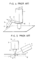
- Figure 3 shows a first conventional combination of a scanning tunnelling microscope and an optical microscope.
- a probe needle 6 is scanned in the plane of a sample surface 7, and is attached to a three-axis micro-drive mechanism 5, operative to enable the needle to undergo vertical movement so as to maintain a constant vertical distance between itself and the sample surface 7.
- An axis 9 which is the centre axis of the needle 6 is inclined with respect to an optical axis 4 of an optical microscope 1 such that concurrent observation can be carried out by the scanning tunnelling microscope and the optical microscope.
- Figure 4 shows a second conventional combination of a scanning tunnelling microscope and an optical microscope.
- a turntable 11 has two or more objective lens 10 of different optical powers mounted thereon.
- a three-axis micro-drive mechanism 5, similar to that referred to in Figure 3, is mounted on the turntable 11 such that the optical axis 4 of the optical microscope 1 and the axis 9 of the needle 6, attached to the three-axis micro-drive mechanism 5, may be selectively to be moved to coincide with a common axis.
- the optical microscope 1 has a relevantly poor resolution power as compared to the dimension of the tip of the needle 6, and so the optical microscope 1 cannot accurately image the actual tip of the needle 6. For these reasons, the optical microscope 1 cannot effect accurate alignment of the axis 9 to a target spot.
- the combination is constructed such that the axis 9 and the optical axis 4 may be moved selectively to coincide with use of the turntable 11. Therefore, concurrent observation is impossible, hence adjustment has to be carried out for the axis 9 each time the needle is replaced. Further, mechanical accuracy must be ensured for switching of the turntable 11. For these reasons, considerable adjustment work is needed each time the needle 6 is replaced and highly accurate machining is also needed for the turntable 11 so as to effect accurate alignment of a target spot by the optical microscope.
- a scanning tunnelling microscope in combination with an optical microscope, characterised in that a probe needle of the scanning tunnelling microscope is disposed in alignment with an optical axis of the optical microscope.
- the optical axis of the optical microscope is a centre line of the optical pass, and an observed image is form of not only the optical beam along the optical axis, but also optical beams through the entire cross section of the optical path. Therefore, when an obstacle blocks are part of the optical pass on the optical axis, the observed image is only darken to the extent that a part of the optical pass is blocked.
- the needle and/or its three-dimensional micro-drive mechanism of the scanning tunnelling microscope are disposed in a part of an optical pass of the optical microscope in alignment with the optical axis.
- the scanning tunnelling microscope and the optical microscope are coaxially aligned with each other so as to enable concurrent observations, thereby to effect accurate alignment of a target spot of the scanning tunnelling microscope by the the optical microscope.
- the optical microscope has a lens sleeve and an objective lens provided at one end of the lens sleeve and formed with a central opening, an electrostriction element of the scanning tunnelling microscope being mounted in the opening and carrying the needle.
- the electrostriction element may have a portion connected to driving electrode means and a portion fixed in the opening of the objective lens.
- the optical microscope has a lens sleeve and an objective lens provided at one end of the lens sleeve and formed with a central opening, an electrostriction element of the scanning tunnelling microscope being mounted on the lens sleeve, the needle being mounted in the opening of the objective lens.
- Figure 1(a) illustrates a first embodiment of a combination according to the present invention of a scanning tunnelling microscope and an optical microscope 1.
- the optical microscope 1 is provided with a lens sleeve 1a.
- An eyepiece 2 is attached to one end of the lens sleeve and an objective lens 3 is attached to the other end.
- the objective lens 3 is formed centrally with an opening 3a.
- the objective lens 3 has a hollow structure such that a central part thereof is removed around an optical axis 4.
- the opening 3a of the hollow objective lens 3 accommodates a three-axis micro-drive mechanism 5 of the scanning tunnelling microscope effective to enable a probe needle 6 to follow vertically a sample surface 7 so as to scan the needle 6 along the sample surface 7 in the plane thereof thereby to maintain constant the distance between the needle 6 and the sample surface.
- the three-axis micro-drive mechanism 5 is composed of a cylindrical electrostriction element which is provided with X-, Y- and Z-drive electrodes 6X, 6Y, 6Z. The electrodes are connected to a driving circuit 15 which applies an appropriate driving voltage.
- the electrostriction element if fixed at its upper end, which is spaced from the drive electrodes, to the objective lens 3 by adhesive.
- the micro-drive mechanism 5 supports, at its lower end, an attachment piece 6a.
- the needle 6, i.e., the measurement needle of the scanning tunnelling microscope is fixed to the attachment piece 6a by a screw or other fitting.
- the axis of the scanning tunnelling microscope or the centre axis of the needle 6 is coaxially aligned with the optical axis 4 or the centre axis of the optical pass of the optical microscope 1.
- Figure 1(b) shows a modification of a combination shown in Figure 1(a) in which driving lead wire of the electrostriction element 5 are arranged through the opening 3a of the objective lens 3 and inside the lens sleeve 1a.
- the sample surface 7 is advanced towards the needle 6 by means of a displacement device (not shown) so that the needle 6 is in the tunnelling region and a target spot observed by the scanning tunnelling microscope.
- the focal depth of the optical microscope 1 is adjusted to enable the optical microscope to observe clearly the sample surface 7.
- the image observed through the optical microscope 1 becomes proportionally dark because light is blocked by the micro-drive mechanism 5.
- the micro-drive mechanism 5 itself is never observed because it is positioned away from the sample surface 7 i.e. is out of the focal plane.
- the optical microscope has a focal depth at least of the order of several micrometers. Accordingly, in the condition where the sample surface 7 and the needle 6 approach each other in the tunnelling range and the focus of the optical microscope is adjusted to the sample surface, a tip end and vicinity thereof of the needle 6 can be observed by the optical microscope. However, the tip end of the needle 6 is far smaller that the actual resolving power of the optical microscope 1, so actual observation of tip end of the needle cannot be effected by the optical microscope 1. Instead, the needle has a conical peripheral portion adjacent to the tip end of the order of several micrometers and sufficient diameter to be observed by the optical microscope.
- this peripheral portion can be clearly observed, since it is within the focal depth of the optical microscope.
- the image of this conical peripheral portion of the needle 6 is observed by the optical microscope 1 in superposed relation to the image of the initially focused sample surface 7. Observation of the scanning tunnelling microscope is effected on to the superposed image portion of the sample surface 7 to which the tip end of the needle 6 is pointed.
- the micro-drive mechanism 5 does not drive the objective lens 3, but only drives the needle 6 so that the electrostriction element of the micro-drive mechanism 5 does not receive an excessive load. This reduces inertia during driving of the electrostriction element to effect accurate scanning of the needle.
- Figure 2 illustrates another embodiment of a combination according to the present invention of optical microscope and scanning tunnelling microscope.
- the needle 6 is arranged in opposed relation to the sample surface 7 and is scanned in the plane thereof.
- a cylindrical three-axis micro-drive mechanism 8 is provided to enable the needle 6 to follow vertically the contours of the sample surface 7 to maintain a constant distance between the sample surface and the needle 6.
- the micro-drive mechanism 8 has a hollow cylindrical structure and opposite open ends.
- One end of the micro-drive mechanism 8 is attached with a hollow annular objective lens 3 which is one component of the optical microscope 1.
- the hollow objective lens 3 has an opening around its optical or centre axis.
- a needle attachment piece 6b is fixed in the opening of the hollow objective lens 3, and the needle 6, ie the measurement needle of the scanning tunnelling microscope, is fixed to the attachment piece 6b by screw or other fitting so that the axis of the scanning tunnelling microscope or the centre axis of the needle 6 is coaxially aligned with the optical axis 4 of the centre axis of the optical pass of the optical microscope 1.
- An eyepiece 2 of the optical microscope 1 is arranged in axially spaced relation from the other end of the micro-drive mechanism 8.
- the sample surface 7 is advanced towards the needle 6 until the latter is within the tunnelling range and in place for observation by the scanning tunnelling microscope. In this condition, the focal distance of the optical microscope 1 is adjusted clearly to observe the sample surface 7 through the optical microscope 1.
- the optical microscope has a focal depth at least of the order of several micrometers such that the optical microscope can observe an object within a axial range of several micrometers relative to the sample surface 7 while the focal plane is adjusted to the sample surface.
- the tip end of the needle 6 is positioned in a range of nanometers from the sample surface 7 such that the tip end is substantially focused by the optical microscope.
- the tip end of the needle 6 is small compared to the resolution power of the optical microscope 1. Thus an actual image of a tip end of the needle 6 cannot be obtained.
- a peripheral portion of the needle 6 axially spaced from the tip by the order of several micrometers has a diameter sufficient to be observed. Therefore, this peripheral portion of the needle 6 within the focal depth can be clearly observed.
- the image of this peripheral portion observed by the optical microscope 1 is seen in superposed relation to the initially focused image of the sample surface 7. Then, measurement by the scanning tunnelling microscope can be carried out onto the superposed image area of the sample surface 7 to which the tip of the needle 6 is directed.
- the amount of offset is normally limited within the observation field of the optical microscope 1, and the axis of the scanning tunnel microscope or the centre axis of the needle is not substantially inclined from the optical axis 4. Therefore, in a manner comparable to the ideal state where the axis of the scanning tunnelling microscope is exactly aligned with the optical axis, the shadow image of the needle 6 superposed on the image of the sample surface 7 by the optical microscope 1 can represent a target spot to be measured by the scanning tunnelling microscope.
- a target spot for observation by the scanning tunnelling microscope can be accurately recognised by the optical microscope, thereby enabling an accurate alignment of the target spot through the optical microscope.
- the invention can eliminate the considerable work of adjustment or alignment of replacement needles and extremely high machining accuracy for complex structures.
Abstract
Description
- This invention relates to scanning tunnelling microscopes in combination with optical microscopes, for example, for use as surface roughness gauges.
- One known scanning tunnelling microscope has a probe needle which is scanned along a sample surface in the direction of the plane of the sample while maintaining a fixed distance between the sample surface and the needle. Utilising the tunnel effect, an atomic image of the sample surface or three-dimensional micro-structure of the sample surface can be determined from the spacial height of the needle. The distance between the sample surface and the needle must be held constant in the order of nanometers to effect flow of tunnel current. Hence, the practical area of visual observation is limited at most to several micrometers. For this reason, in order to observe a particular spot on the sample surface, a supplementary observation instrument, such as an optical microscope, needs to be combined with the scanning tunnelling microscope.
- Figure 3 shows a first conventional combination of a scanning tunnelling microscope and an optical microscope. A
probe needle 6 is scanned in the plane of asample surface 7, and is attached to a three-axismicro-drive mechanism 5, operative to enable the needle to undergo vertical movement so as to maintain a constant vertical distance between itself and thesample surface 7. Anaxis 9 which is the centre axis of theneedle 6 is inclined with respect to anoptical axis 4 of anoptical microscope 1 such that concurrent observation can be carried out by the scanning tunnelling microscope and the optical microscope. - Figure 4 shows a second conventional combination of a scanning tunnelling microscope and an optical microscope. A
turntable 11 has two or moreobjective lens 10 of different optical powers mounted thereon. A three-axismicro-drive mechanism 5, similar to that referred to in Figure 3, is mounted on theturntable 11 such that theoptical axis 4 of theoptical microscope 1 and theaxis 9 of theneedle 6, attached to the three-axismicro-drive mechanism 5, may be selectively to be moved to coincide with a common axis. - However, with regard to the conventional combination of scanning tunnelling microscope and optical microscope shown in Figure 3, the
axis 9 and theoptical axis 4 are angularly offset from each other. Therefore, as illustrated in Figure 5, there is the drawback that when the distance between thesample surface 7 and theneedle 6 is varied a spot position on thesample surface 7 pointed to by a tip of theneedle 6 is shifted as indicated bynumerals optical microscope 1. Therefore, when advancing theneedle 6 from arest position level 12 to thesample surface 7 for observation by the scanning tunnelling microscope, a particular spot position on thesample surface 7 pointed to the tip of theneedle 6 cannot be correctly observed byoptical microscope 1 due to view angle difference. Further, theoptical microscope 1 has a relevantly poor resolution power as compared to the dimension of the tip of theneedle 6, and so theoptical microscope 1 cannot accurately image the actual tip of theneedle 6. For these reasons, theoptical microscope 1 cannot effect accurate alignment of theaxis 9 to a target spot. - With regard to the conventional combination of scanning tunnelling microscope and optical microscope shown in Figure 4, the combination is constructed such that the
axis 9 and theoptical axis 4 may be moved selectively to coincide with use of theturntable 11. Therefore, concurrent observation is impossible, hence adjustment has to be carried out for theaxis 9 each time the needle is replaced. Further, mechanical accuracy must be ensured for switching of theturntable 11. For these reasons, considerable adjustment work is needed each time theneedle 6 is replaced and highly accurate machining is also needed for theturntable 11 so as to effect accurate alignment of a target spot by the optical microscope. - The above noted problems are caused by either the fact that the axis of the needle of the scanning tunnelling microscope is not aligned with the optical axis of the optical microscope or the fact that concurrent observation by the scanning tunnelling microscope and the optical microscope is not possible.
- According to the present invention there is provided a scanning tunnelling microscope in combination with an optical microscope, characterised in that a probe needle of the scanning tunnelling microscope is disposed in alignment with an optical axis of the optical microscope.
- The optical axis of the optical microscope is a centre line of the optical pass, and an observed image is form of not only the optical beam along the optical axis, but also optical beams through the entire cross section of the optical path. Therefore, when an obstacle blocks are part of the optical pass on the optical axis, the observed image is only darken to the extent that a part of the optical pass is blocked. By utilising this phenomenon, the needle and/or its three-dimensional micro-drive mechanism of the scanning tunnelling microscope are disposed in a part of an optical pass of the optical microscope in alignment with the optical axis.
- In such a construction, the scanning tunnelling microscope and the optical microscope are coaxially aligned with each other so as to enable concurrent observations, thereby to effect accurate alignment of a target spot of the scanning tunnelling microscope by the the optical microscope.
- In one embodiment of the present invention the optical microscope has a lens sleeve and an objective lens provided at one end of the lens sleeve and formed with a central opening, an electrostriction element of the scanning tunnelling microscope being mounted in the opening and carrying the needle. The electrostriction element may have a portion connected to driving electrode means and a portion fixed in the opening of the objective lens.
- In another embodiment the optical microscope has a lens sleeve and an objective lens provided at one end of the lens sleeve and formed with a central opening, an electrostriction element of the scanning tunnelling microscope being mounted on the lens sleeve, the needle being mounted in the opening of the objective lens.
- The invention is illustrated, by way of example, in the accompanying drawings, in which:-
- Figure 1(a) shows a first embodiment of a combination according to the present invention of an optical microscope and a scanning tunnelling microscope;
- Figure 1(b) shows a modification of the first embodiment shown in Figure 1(a):
- Figure 2 shows a second embodiment of a combination according to the present invention of an optical microscope and a scanning tunnelling microscope;
- Figure 3 shows a first a conventional combination of an optical microscope and a scanning tunnelling microscope;
- Figure 4 shows a second conventional combination of an optical microscope and an scanning tunnelling microscope; and
- Figure 5 is explanatory diagram illustrating the drawback of the first conventional combination of optical microscope and scanning tunnelling microscope.
- Throughout the drawings like parts have been designated by the same reference numerals.
- Figure 1(a) illustrates a first embodiment of a combination according to the present invention of a scanning tunnelling microscope and an
optical microscope 1. Theoptical microscope 1 is provided with alens sleeve 1a. Aneyepiece 2 is attached to one end of the lens sleeve and anobjective lens 3 is attached to the other end. Theobjective lens 3 is formed centrally with an opening 3a. In other words, theobjective lens 3 has a hollow structure such that a central part thereof is removed around anoptical axis 4. Theopening 3a of the hollowobjective lens 3 accommodates a three-axis micro-drive mechanism 5 of the scanning tunnelling microscope effective to enable aprobe needle 6 to follow vertically asample surface 7 so as to scan theneedle 6 along thesample surface 7 in the plane thereof thereby to maintain constant the distance between theneedle 6 and the sample surface. The three-axis micro-drive mechanism 5 is composed of a cylindrical electrostriction element which is provided with X-, Y- and Z-drive electrodes driving circuit 15 which applies an appropriate driving voltage. The electrostriction element if fixed at its upper end, which is spaced from the drive electrodes, to theobjective lens 3 by adhesive. Themicro-drive mechanism 5 supports, at its lower end, anattachment piece 6a. Theneedle 6, i.e., the measurement needle of the scanning tunnelling microscope is fixed to theattachment piece 6a by a screw or other fitting. The axis of the scanning tunnelling microscope or the centre axis of theneedle 6 is coaxially aligned with theoptical axis 4 or the centre axis of the optical pass of theoptical microscope 1. - Figure 1(b) shows a modification of a combination shown in Figure 1(a) in which driving lead wire of the
electrostriction element 5 are arranged through the opening 3a of theobjective lens 3 and inside thelens sleeve 1a. - In the above described embodiment of the present invention, the
sample surface 7 is advanced towards theneedle 6 by means of a displacement device (not shown) so that theneedle 6 is in the tunnelling region and a target spot observed by the scanning tunnelling microscope. In this position, the focal depth of theoptical microscope 1 is adjusted to enable the optical microscope to observe clearly thesample surface 7. In this state, the image observed through theoptical microscope 1 becomes proportionally dark because light is blocked by themicro-drive mechanism 5. However, themicro-drive mechanism 5 itself is never observed because it is positioned away from thesample surface 7 i.e. is out of the focal plane. - Further, when the
sample surface 7 approaches theneedle 6 in the tunnelling range, its distance is of the order of nanometers. On the other hand, the optical microscope has a focal depth at least of the order of several micrometers. Accordingly, in the condition where thesample surface 7 and theneedle 6 approach each other in the tunnelling range and the focus of the optical microscope is adjusted to the sample surface, a tip end and vicinity thereof of theneedle 6 can be observed by the optical microscope. However, the tip end of theneedle 6 is far smaller that the actual resolving power of theoptical microscope 1, so actual observation of tip end of the needle cannot be effected by theoptical microscope 1. Instead, the needle has a conical peripheral portion adjacent to the tip end of the order of several micrometers and sufficient diameter to be observed by the optical microscope. Therefore, this peripheral portion can be clearly observed, since it is within the focal depth of the optical microscope. The image of this conical peripheral portion of theneedle 6 is observed by theoptical microscope 1 in superposed relation to the image of the initially focusedsample surface 7. Observation of the scanning tunnelling microscope is effected on to the superposed image portion of thesample surface 7 to which the tip end of theneedle 6 is pointed. - With regard to horizontal offset of the tip end of the
needle 6 in a direction parallel to thesample surface 7, which would occur everytime theneedle 6 was replaced, this offset is limited normally within the observation field of the optical microscope and the centre axis of the needle which is not substantially inclined relative to theoptical axis 4. Therefore, in similar manner to the case where the axis of the scanning tunnelling microscope is exactly coaxially with theoptical axis 4, the shadow image of theneedle 6 obtained by theoptical microscope 1 in superposed relation to the image of the sample surface is effective to designate to a target spot of observation by the scanning tunnelling microscope. - In this embodiment, the
micro-drive mechanism 5 does not drive theobjective lens 3, but only drives theneedle 6 so that the electrostriction element of themicro-drive mechanism 5 does not receive an excessive load. This reduces inertia during driving of the electrostriction element to effect accurate scanning of the needle. - Figure 2 illustrates another embodiment of a combination according to the present invention of optical microscope and scanning tunnelling microscope. The
needle 6 is arranged in opposed relation to thesample surface 7 and is scanned in the plane thereof. Further, a cylindrical three-axis micro-drive mechanism 8 is provided to enable theneedle 6 to follow vertically the contours of thesample surface 7 to maintain a constant distance between the sample surface and theneedle 6. The micro-drive mechanism 8 has a hollow cylindrical structure and opposite open ends. One end of the micro-drive mechanism 8 is attached with a hollow annularobjective lens 3 which is one component of theoptical microscope 1. The hollowobjective lens 3 has an opening around its optical or centre axis. Aneedle attachment piece 6b is fixed in the opening of the hollowobjective lens 3, and theneedle 6, ie the measurement needle of the scanning tunnelling microscope, is fixed to theattachment piece 6b by screw or other fitting so that the axis of the scanning tunnelling microscope or the centre axis of theneedle 6 is coaxially aligned with theoptical axis 4 of the centre axis of the optical pass of theoptical microscope 1. - An
eyepiece 2 of theoptical microscope 1 is arranged in axially spaced relation from the other end of the micro-drive mechanism 8. - In the above described construction, the
sample surface 7 is advanced towards theneedle 6 until the latter is within the tunnelling range and in place for observation by the scanning tunnelling microscope. In this condition, the focal distance of theoptical microscope 1 is adjusted clearly to observe thesample surface 7 through theoptical microscope 1. - While the image observed by the
optical microscope 1 is proportionally darkened because light is blocked by the stem of theneedle 6, the stem itself does not appear in the observed image because it is positioned far away from the focal plane of thesample surface 7. - Next, with regard to the observed image of the tip of the
needle 6 by theoptical microscope 1, generally the optical microscope has a focal depth at least of the order of several micrometers such that the optical microscope can observe an object within a axial range of several micrometers relative to thesample surface 7 while the focal plane is adjusted to the sample surface. In this regard, the tip end of theneedle 6 is positioned in a range of nanometers from thesample surface 7 such that the tip end is substantially focused by the optical microscope. However, the tip end of theneedle 6 is small compared to the resolution power of theoptical microscope 1. Thus an actual image of a tip end of theneedle 6 cannot be obtained. On the other hand, a peripheral portion of theneedle 6 axially spaced from the tip by the order of several micrometers has a diameter sufficient to be observed. Therefore, this peripheral portion of theneedle 6 within the focal depth can be clearly observed. The image of this peripheral portion observed by theoptical microscope 1 is seen in superposed relation to the initially focused image of thesample surface 7. Then, measurement by the scanning tunnelling microscope can be carried out onto the superposed image area of thesample surface 7 to which the tip of theneedle 6 is directed. - Further, with regard to offset of the tip of the
needle 6 in the direction ofsample surface 7, which would occur everytime the needle was replaced, the amount of offset is normally limited within the observation field of theoptical microscope 1, and the axis of the scanning tunnel microscope or the centre axis of the needle is not substantially inclined from theoptical axis 4. Therefore, in a manner comparable to the ideal state where the axis of the scanning tunnelling microscope is exactly aligned with the optical axis, the shadow image of theneedle 6 superposed on the image of thesample surface 7 by theoptical microscope 1 can represent a target spot to be measured by the scanning tunnelling microscope. - As described above, a target spot for observation by the scanning tunnelling microscope can be accurately recognised by the optical microscope, thereby enabling an accurate alignment of the target spot through the optical microscope. Further, the invention can eliminate the considerable work of adjustment or alignment of replacement needles and extremely high machining accuracy for complex structures.
Claims (5)
Applications Claiming Priority (2)
| Application Number | Priority Date | Filing Date | Title |
|---|---|---|---|
| JP1167760A JPH0334250A (en) | 1989-06-29 | 1989-06-29 | Optical microscope complex scanning type tunnel microscope |
| JP167760/89 | 1989-06-29 |
Publications (2)
| Publication Number | Publication Date |
|---|---|
| EP0405973A1 true EP0405973A1 (en) | 1991-01-02 |
| EP0405973B1 EP0405973B1 (en) | 1994-12-07 |
Family
ID=15855586
Family Applications (1)
| Application Number | Title | Priority Date | Filing Date |
|---|---|---|---|
| EP90307082A Expired - Lifetime EP0405973B1 (en) | 1989-06-29 | 1990-06-28 | Scanning tunnelling microscope in combination with an optical microscope |
Country Status (3)
| Country | Link |
|---|---|
| EP (1) | EP0405973B1 (en) |
| JP (1) | JPH0334250A (en) |
| DE (1) | DE69014733T2 (en) |
Cited By (3)
| Publication number | Priority date | Publication date | Assignee | Title |
|---|---|---|---|---|
| EP0509856A1 (en) * | 1991-03-15 | 1992-10-21 | Nikon Corporation | Scanning probe type microscope combined with an optical microscope |
| EP0527601A1 (en) * | 1991-08-08 | 1993-02-17 | Nikon Corporation | Composite scanning tunnelling microscope and optical microscope |
| US5689063A (en) * | 1993-07-15 | 1997-11-18 | Nikon Corporation | Atomic force microscope using cantilever attached to optical microscope |
Citations (1)
| Publication number | Priority date | Publication date | Assignee | Title |
|---|---|---|---|---|
| WO1989001603A1 (en) * | 1987-08-12 | 1989-02-23 | Olympus Optical Co., Ltd. | Scanning type tunnel microscope |
Family Cites Families (1)
| Publication number | Priority date | Publication date | Assignee | Title |
|---|---|---|---|---|
| EP0331148B1 (en) * | 1988-03-04 | 1994-07-13 | Kabushiki Kaisha Toshiba | Microscope apparatus |
-
1989
- 1989-06-29 JP JP1167760A patent/JPH0334250A/en active Pending
-
1990
- 1990-06-28 EP EP90307082A patent/EP0405973B1/en not_active Expired - Lifetime
- 1990-06-28 DE DE69014733T patent/DE69014733T2/en not_active Expired - Fee Related
Patent Citations (1)
| Publication number | Priority date | Publication date | Assignee | Title |
|---|---|---|---|---|
| WO1989001603A1 (en) * | 1987-08-12 | 1989-02-23 | Olympus Optical Co., Ltd. | Scanning type tunnel microscope |
Non-Patent Citations (1)
| Title |
|---|
| JOURNAL OF VACUUM SCIENCE AND TECHNOLOGY: PART A. vol. 6, no. 2, April 1988, NEW YORK US pages 383 - 385; Guckenberger R. et al.: "Design of STM for biological applications" * |
Cited By (5)
| Publication number | Priority date | Publication date | Assignee | Title |
|---|---|---|---|---|
| EP0509856A1 (en) * | 1991-03-15 | 1992-10-21 | Nikon Corporation | Scanning probe type microscope combined with an optical microscope |
| US5508517A (en) * | 1991-03-15 | 1996-04-16 | Nikon Corporation | Scanning probe type microscope apparatus |
| EP0527601A1 (en) * | 1991-08-08 | 1993-02-17 | Nikon Corporation | Composite scanning tunnelling microscope and optical microscope |
| US5276324A (en) * | 1991-08-08 | 1994-01-04 | Nikon Corporation | Composite scanning tunneling microscope |
| US5689063A (en) * | 1993-07-15 | 1997-11-18 | Nikon Corporation | Atomic force microscope using cantilever attached to optical microscope |
Also Published As
| Publication number | Publication date |
|---|---|
| DE69014733D1 (en) | 1995-01-19 |
| DE69014733T2 (en) | 1995-04-27 |
| EP0405973B1 (en) | 1994-12-07 |
| JPH0334250A (en) | 1991-02-14 |
Similar Documents
| Publication | Publication Date | Title |
|---|---|---|
| EP0331148B1 (en) | Microscope apparatus | |
| US6127681A (en) | Scanning tunnel microscope | |
| EP1430485B1 (en) | Device and method for scanning probe microscope | |
| KR100192097B1 (en) | Configuration measuring method and apparatus for optically detecting a displacement of a probe due to an atomic force | |
| EP3479157B1 (en) | Inclination measurement and correction of the cover glass in the optical path of a microscope | |
| JPH03205502A (en) | Scanning type tunnel microscope | |
| DE19923821A1 (en) | Method and device for recording the position of a surface to be scanned with a laser scanner includes a microscope beam input directed through a microscope lens onto a lens with a biochip to pick up fluorescent samples. | |
| DE10139920B4 (en) | Scanning microscope and method for scanning an object | |
| DE10050529A1 (en) | Method for beam control in a scanning microscope, arrangement for beam control in a scanning microscope and scanning microscope | |
| EP0405973B1 (en) | Scanning tunnelling microscope in combination with an optical microscope | |
| DE112006000419T5 (en) | Scanning Probe Microscope Offset Detection Mechanism and Scanning Probe Microscope Using the Same | |
| KR920005446B1 (en) | Telescope apparatus | |
| EP0139967B1 (en) | Method and apparatus for the performance of several complementary microscopic investigations | |
| DE3720079C2 (en) | ||
| JP3126047B2 (en) | Scanning probe microscope | |
| JPH0371001A (en) | Fine surface shape measuring instrument | |
| DE19546860C2 (en) | Device for measuring the relative movement between a probe and a probe head in scanning probe microscopy | |
| DE4201482A1 (en) | OPTICAL PROBE | |
| DE10226801B4 (en) | Surface measuring device and method for mechanical and non-contact optical examination of object surfaces | |
| DE1928432A1 (en) | Arrangement for stabilizing the focus of the objective of an optical instrument | |
| DE10039337A1 (en) | Combination of scanning and imaging methods when checking photomasks | |
| JPS6283716A (en) | Focus position adjusting device for laser drawing device | |
| JPH0541922B2 (en) | ||
| JPS62119847A (en) | Charged beam device | |
| JPH05340713A (en) | Surface measuring instrument |
Legal Events
| Date | Code | Title | Description |
|---|---|---|---|
| PUAI | Public reference made under article 153(3) epc to a published international application that has entered the european phase |
Free format text: ORIGINAL CODE: 0009012 |
|
| AK | Designated contracting states |
Kind code of ref document: A1 Designated state(s): CH DE FR GB LI |
|
| 17P | Request for examination filed |
Effective date: 19910625 |
|
| 17Q | First examination report despatched |
Effective date: 19930415 |
|
| GRAA | (expected) grant |
Free format text: ORIGINAL CODE: 0009210 |
|
| AK | Designated contracting states |
Kind code of ref document: B1 Designated state(s): CH DE FR GB LI |
|
| REF | Corresponds to: |
Ref document number: 69014733 Country of ref document: DE Date of ref document: 19950119 |
|
| ET | Fr: translation filed | ||
| PLBE | No opposition filed within time limit |
Free format text: ORIGINAL CODE: 0009261 |
|
| STAA | Information on the status of an ep patent application or granted ep patent |
Free format text: STATUS: NO OPPOSITION FILED WITHIN TIME LIMIT |
|
| 26N | No opposition filed | ||
| REG | Reference to a national code |
Ref country code: GB Ref legal event code: IF02 |
|
| REG | Reference to a national code |
Ref country code: CH Ref legal event code: PUE Owner name: SII NANOTECHNOLOGY INC. Free format text: SEIKO INSTRUMENTS INC.#31-1, 6-CHOME, KAMEIDO#KOTO-KU/TOKYO (JP) -TRANSFER TO- SII NANOTECHNOLOGY INC.#8 NAKASE 1-CHOME, MIHAMA-KU#CHIBA-SHI, CHIBA 261-8507 (JP) Ref country code: CH Ref legal event code: NV Representative=s name: PATENTANWAELTE SCHAAD, BALASS, MENZL & PARTNER AG |
|
| REG | Reference to a national code |
Ref country code: GB Ref legal event code: 732E |
|
| REG | Reference to a national code |
Ref country code: FR Ref legal event code: TP |
|
| PGFP | Annual fee paid to national office [announced via postgrant information from national office to epo] |
Ref country code: FR Payment date: 20060608 Year of fee payment: 17 |
|
| PGFP | Annual fee paid to national office [announced via postgrant information from national office to epo] |
Ref country code: GB Payment date: 20060628 Year of fee payment: 17 Ref country code: CH Payment date: 20060628 Year of fee payment: 17 |
|
| REG | Reference to a national code |
Ref country code: CH Ref legal event code: PL |
|
| GBPC | Gb: european patent ceased through non-payment of renewal fee |
Effective date: 20070628 |
|
| REG | Reference to a national code |
Ref country code: FR Ref legal event code: ST Effective date: 20080229 |
|
| PG25 | Lapsed in a contracting state [announced via postgrant information from national office to epo] |
Ref country code: CH Free format text: LAPSE BECAUSE OF NON-PAYMENT OF DUE FEES Effective date: 20070630 Ref country code: LI Free format text: LAPSE BECAUSE OF NON-PAYMENT OF DUE FEES Effective date: 20070630 |
|
| PG25 | Lapsed in a contracting state [announced via postgrant information from national office to epo] |
Ref country code: GB Free format text: LAPSE BECAUSE OF NON-PAYMENT OF DUE FEES Effective date: 20070628 |
|
| PG25 | Lapsed in a contracting state [announced via postgrant information from national office to epo] |
Ref country code: FR Free format text: LAPSE BECAUSE OF NON-PAYMENT OF DUE FEES Effective date: 20070702 |
|
| PGFP | Annual fee paid to national office [announced via postgrant information from national office to epo] |
Ref country code: DE Payment date: 20080703 Year of fee payment: 19 |
|
| PG25 | Lapsed in a contracting state [announced via postgrant information from national office to epo] |
Ref country code: DE Free format text: LAPSE BECAUSE OF NON-PAYMENT OF DUE FEES Effective date: 20100101 |