EP0406667B1 - Forming method of patterned coating - Google Patents
Forming method of patterned coating Download PDFInfo
- Publication number
- EP0406667B1 EP0406667B1 EP90112121A EP90112121A EP0406667B1 EP 0406667 B1 EP0406667 B1 EP 0406667B1 EP 90112121 A EP90112121 A EP 90112121A EP 90112121 A EP90112121 A EP 90112121A EP 0406667 B1 EP0406667 B1 EP 0406667B1
- Authority
- EP
- European Patent Office
- Prior art keywords
- magnetic
- module
- substrate
- pattern
- elements
- Prior art date
- Legal status (The legal status is an assumption and is not a legal conclusion. Google has not performed a legal analysis and makes no representation as to the accuracy of the status listed.)
- Expired - Lifetime
Links
Images


Classifications
-
- B—PERFORMING OPERATIONS; TRANSPORTING
- B05—SPRAYING OR ATOMISING IN GENERAL; APPLYING FLUENT MATERIALS TO SURFACES, IN GENERAL
- B05D—PROCESSES FOR APPLYING FLUENT MATERIALS TO SURFACES, IN GENERAL
- B05D5/00—Processes for applying liquids or other fluent materials to surfaces to obtain special surface effects, finishes or structures
-
- B—PERFORMING OPERATIONS; TRANSPORTING
- B05—SPRAYING OR ATOMISING IN GENERAL; APPLYING FLUENT MATERIALS TO SURFACES, IN GENERAL
- B05D—PROCESSES FOR APPLYING FLUENT MATERIALS TO SURFACES, IN GENERAL
- B05D3/00—Pretreatment of surfaces to which liquids or other fluent materials are to be applied; After-treatment of applied coatings, e.g. intermediate treating of an applied coating preparatory to subsequent applications of liquids or other fluent materials
- B05D3/20—Pretreatment of surfaces to which liquids or other fluent materials are to be applied; After-treatment of applied coatings, e.g. intermediate treating of an applied coating preparatory to subsequent applications of liquids or other fluent materials by magnetic fields
- B05D3/203—Pretreatment of surfaces to which liquids or other fluent materials are to be applied; After-treatment of applied coatings, e.g. intermediate treating of an applied coating preparatory to subsequent applications of liquids or other fluent materials by magnetic fields pre-treatment by magnetic fields
-
- B—PERFORMING OPERATIONS; TRANSPORTING
- B05—SPRAYING OR ATOMISING IN GENERAL; APPLYING FLUENT MATERIALS TO SURFACES, IN GENERAL
- B05D—PROCESSES FOR APPLYING FLUENT MATERIALS TO SURFACES, IN GENERAL
- B05D5/00—Processes for applying liquids or other fluent materials to surfaces to obtain special surface effects, finishes or structures
- B05D5/06—Processes for applying liquids or other fluent materials to surfaces to obtain special surface effects, finishes or structures to obtain multicolour or other optical effects
- B05D5/061—Special surface effect
-
- B—PERFORMING OPERATIONS; TRANSPORTING
- B44—DECORATIVE ARTS
- B44C—PRODUCING DECORATIVE EFFECTS; MOSAICS; TARSIA WORK; PAPERHANGING
- B44C1/00—Processes, not specifically provided for elsewhere, for producing decorative surface effects
- B44C1/04—Producing precipitations
-
- H—ELECTRICITY
- H01—ELECTRIC ELEMENTS
- H01F—MAGNETS; INDUCTANCES; TRANSFORMERS; SELECTION OF MATERIALS FOR THEIR MAGNETIC PROPERTIES
- H01F41/00—Apparatus or processes specially adapted for manufacturing or assembling magnets, inductances or transformers; Apparatus or processes specially adapted for manufacturing materials characterised by their magnetic properties
- H01F41/14—Apparatus or processes specially adapted for manufacturing or assembling magnets, inductances or transformers; Apparatus or processes specially adapted for manufacturing materials characterised by their magnetic properties for applying magnetic films to substrates
- H01F41/16—Apparatus or processes specially adapted for manufacturing or assembling magnets, inductances or transformers; Apparatus or processes specially adapted for manufacturing materials characterised by their magnetic properties for applying magnetic films to substrates the magnetic material being applied in the form of particles, e.g. by serigraphy, to form thick magnetic films or precursors therefor
-
- H—ELECTRICITY
- H01—ELECTRIC ELEMENTS
- H01F—MAGNETS; INDUCTANCES; TRANSFORMERS; SELECTION OF MATERIALS FOR THEIR MAGNETIC PROPERTIES
- H01F7/00—Magnets
- H01F7/02—Permanent magnets [PM]
Definitions
- This invention relates to a forming method of patterned coating upon miscellaneous surfaces, especially a method for illustrating various letters, characters, or figures upon a coated surface in a different tone of configuration from adjacent areas.
- Japanese Patent Public Disclosure No. 175670/1988 there is disclosed a forming method of patterned coating utilizing a magnetic force.
- a liquid coating material containing powdery magnetic materials such as nickel, stainless steel or iron
- a magnet is brought near.
- the powdery magnetic materials which are uniformly dispersed within the liquid coating material, move along magnetic force lines within the coating film, thereby producing a configuration pattern different from adjacent areas.
- Japanese Patent Public Disclosure No. 10376/1982 there is disclosed a manufacturing method of metallic plate having a patterned coating. According to this method, at first a liquid paint containing an iron oxide is coated upon a metallic plate. Then, a magnetic pole is brought near the coated film, so that a pattern corresponding to the magnetic pole appears upon the film. And then, a baking treatment is applied to the coated film to finish the coated layer.
- Another object of the present invention is to overcome the above drawbacks of the conventional forming method and to provide an explicit pattern within a coating film object utilizing a magnetic force. Another object of the present invention is to provide a forming method capable of illustrating miscellaneous patterns without being restricted by the shape of the magnet itself.
- a single magnetic plate has been so magnetized that its flat surface exhibits spaced apart parallel lines extending right across the plate in one direction only and of N polarity with a single line line of S polarity between each adjacent pair of lines of N polarity.
- this plate is used to create a patterned coating on a surface, only a pattern of spaced apart parallel lines is produced.
- this first embodiment cannot be used for producing a continuous visible pattern illustrating, for example, a letter, character or figure.
- a pattern is shown that is said to have resulted from the use of a six pole ring magnet, the pattern showing a ring-shaped area divided into six spaced apart portions.
- two very long magnets are placed in spaced apart parallel array and between these there are arranged two rows of other magnets, said rows being parallel to the long magnets.
- Each of said rows comprises short magnets interspersed with round magnets.
- Another object of the present invention is to overcome the above drawbacks of the conventional forming methods and to provide an explicit pattern within a coating film object utilizing magnetic forces. Another object of the present invention is to provide a forming method capable of illustrating miscellaneous patterns without being restricted by the shape of the magnet itself.
- a method of forming a visible patterned coating upon a surface of a non-magnetizable substrate includes the steps of: preparing a plurality of separate magnetic elements composed within an arrayed module of the elements with the poles of each magnet disposed in a common plane parallel to the substrate with each pole of each magnetic element being closely disposed to an opposite pole of an adjacent magnetic element, bringing said module in close vicinity to a reverse side of a non-magnetizable substrate, appplying a layer of a magnetic paint containing a powdery magnetic material upon the surface of said substrate opposite the reverse side of the substrate to make a wet film thereon, whereby, due to the magnetic field of the module the visible patterned coating is formed in the layer of the magnetic paint due to movement of the powdery magnetic material in response to the magnetic force lines of separated magnetic elements in the module, which visible patterned coating differs in tone from adjacent areas in the layer of magnetic paint, and hardening the wet film through a baking or drying, thereby providing
- a method of forming a visible patterned coating upon a surface of a non-magnetizable substrate includes the steps of: preparing a plurality of separate magnetic elements composed within an arrayed module of the elements with the poles of each magnet disposed in a common plane parallel to the substrate with each pole of each magnetic element being closely disposed to an opposite pole of an adjacent magnetic element, applying a layer of magnetic paint containing a powdery magnetic material upon a surface of a non-magnetizable substrate to make a wet film thereon, bringing said module toward the surface or reverse side of said coated substrate in close vicinity of said wet film while the wet film retains its fluidity, whereby, due to the magnetic field of the module, the visible patterned coating is formed in the layer of the magnetic paint due to movement of the powdery magnetic material in response to the magnetic force lines of separated magnetic elements in the module, which visible patterned coating differs in tone from adjacent areas in the layer of magnetic paint, and hardening the wet film through a baking
- an imaginary chain of magnetic force lines is formed along the module of the elements, and then a substrate is introduced into the magnetic field and exposed to the magnetic power.
- magnetic paint containing powdery magnetic material is sprayed to the surface of the substrate, magnetic fine particles instantly begins to move within the wet film toward the direction of the magnetic force lines.
- the movements of the magnetic material slow down and terminate near the magnetic force lines.
- an explicit continuous pattern corresponding to the configuration pattern of the module appears in a hardened film.
- the appearence of the pattern is not always identical with the configuration pattern of the magnetic chain, since magnetic force lines vary depending upon the directions of the magnetic elements, especially upon the positions of North magnetic poles and South magnetic poles carried on the elements. It should be appreciated that a delicate pattern can be illustrated in the hardened film by changing the direction of each magnetic element.
- a metallic magnet ferrite magnet, sintered magnet or flexible magnet may be used depending upon the shape or magnetic properties.
- these magnetic elements are formed through a moulding process into a relatively small piece having a rectangular, triangular, polygonal or circular configuration.
- any pattern can be illustrated.
- a module of magnetic elements and a magnetic paint coated substrate are prepared in separately. And then, the magnetic paint coated substrate is introduced into a magnetic field produced by the module while the wet film of magnetic paint keeps its fluidity. As the coated substrate is inserted into the magnetic field and exposed to the magnetic power, magnetic fine particles instantly begin to move within the wet film toward the direction of the magnetic force lines. As the wet film loses its fluidity, the movements of the magnetic material slow down and finally terminate near the magnetic force lines. Thus, an explicit continuous pattern corresponding to the configuration pattern of the module appears in the magnetic paint film.
- each magnetic element comprises a rectangular or circular metallic plate having a North magnetic pole and a South magnetic pole situated at the opposite edges thereof; adjacent magnetic elements being disposed in accordance with the present invention such that the North magnetic pole of one element is positioned in close vicinity of the South magnetic pole of the other element.
- the magnetic elements comprise bar-shape or U-shape magnets each having a North magnetic pole and a South magnetic pole situated at the opposite edges thereof, and each magnet is perpendicularly disposed to the substrate.
- the magnetic elements are filled up within a rubber or plastic sheet in a plurality of striped patterns.
- the magnetic powder to be contained in the magnetic paint stainless steel powder, ferrous powder, Fe3O4 coated mica powder, alloy powder containing iron, cobalt and cickel, magnetic iron oxide coated resin particles or the like may be utilized as far as it can move within the wet film or change its direction under the influence of a magnetic force.
- the aforementioned Fe3O4 coated mica powder is well known as a nacreous pigment of paint. It should be noted that an ordinary pigment can be utilized in the present invention as far as it has a property to be influenced by a magnetic force.
- any kind of ordinary paint can be utilized as far as it can form a cured film after having finished a series of processes including a coating under a fluid condition and a baking or drying to harden the film.
- the magnetic paint includes, other than the magnetic powder, a pigment, vehicle resin, curing agent, solvent or the like.
- the containing ratio of the magnetic powder relative to the magnetic paint is determined in a range such that an explicit pattern appears under the influence of a magnetic force. According to an experiment, the ratio is preferably more than 0.1 percent of the magnetic paint by weight.
- the magnetic paint may be selected from an ordinary type which is hardened by a baking process or air drying process under the ambient temperature.
- the coating system can be selected from the following:
- this invention can apply to miscellaneous coating processes including more complicated coating steps, as far as the wet film is magnetically accessible from outside.
- a base color coating is formed upon a surface of a substrate as a first-coated layer
- magnetic paint can be applied to the surface as an additional ornamental layer.
- some portions of the ornamental layer becomes thinner under the influence of a magnetic force.
- some portions of the first-coated layer appear and provide delicate color patterns which have not yet been illustrated.
- non-magnetizable material such as synthetic resin, rubber, ceramic or aluminum plate is preferable, since these materials do not affect the magnetic force of the magnetic element.
- some kinds of magnetizable materials may be used.
- the influence is small.
- such approaching operation toward the surface is not desirable because a collision may happen between the wet film and the magnetic elements, resulting in a destruction of the coated layer.
- the module of the magnetic elements should be supported on a guiding device, which may comprise a supporting rail, handling arm or similar member.
- a guiding device which may comprise a supporting rail, handling arm or similar member.
- the forming method of the invention can be preferably utilized for illustrating various letters, characters, or figures upon a coated surface.
- the method can be utilized for representing a repetitive pattern over a large area of the substrate. In this case, a plurality of magnetic modules are prepared or a single module is repeatedly used.
- FIG. 1 is a plan view of a reverse side of a substrate to be coated utilizing the method of the present invention.
- FIG. 2 is a sectional view taken along the line A -A in FIG. 1.
- FIG. 3 is a plan view of the surface of the substrate which is coated by the method of the present invention.
- FIG. 4 is a sectional view of an alternative embodiment similar to FIG. 2.
- FIG. 5 is a plan view illustrating an alternative module of multi-pole type magnetic elements.
- FIG. 6 is a perspective view of a modified module utilizing column-type magnetic elements.
- FIG. 7 is a plan view illustrating an arrangement of circular magnetic elements.
- FIG. 8 is a plan view illustrating an alternative arrangement of the magnetic elements in FIG. 7.
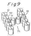
- FIG. 9 is a perspective view of a modified arrangement utilizing a combination of several types of magnetic elements.
- FIGS. 1 to 3 there is shown a first embodiment utilizing the method of the present invention.
- an arrayed module 15 which comprises a plurality of rectangular magnetic elements 11 supported on a sticking tape 30.
- Each of the magnetic elements 11 carries a North magnetic pole and a South magnetic pole at the opposite edges.
- the magnetic elements 11 are disposed side by side, and adjacent elements 11 are disposed such that the North pole of one element is positioned in close vicinity of the South pole of the other element, and that the South pole of the one element is positioned in close vicinity of the North pole of the other element. Accordingly, strong magnetic force lines are produced between the elements, of course in an imaginary form.
- FIG. 2 shows a relationship among the coated paint 20, the substrate 10, the magnetic element 11 and the sticking tape 30. It should be noted that the element 11 is firmly sticked to the substrate 10 by the sticking tape 30.
- FIG. 3 shows a surface which has been coated with magnetic paint.
- magnetic paint is sprayed on the surface. Since an imaginary chain of magnetic force lines is formed along the module 15, as soon as the magnetic paint is thrown into the magnetic field and applied to the surface of the substrate, magnetic fine particles instantly begin to move within a wet film of the magnetic paint toward the direction of the magnetic force lines. As the wet film loses its fluidity, the movements of the magnetic material slow down and finally terminate near the magnetic force lines.
- a transitional area 24 in which a color tone is different from that of the adjacent area appears on the surface of the substrate 10.
- the configuration of the area 24 is corresponding to the configuration pattern of the module 15. It should be noted that the configuration of the pattern 24 is not identical with the configuration pattern of the separated magnetic elements 11.
- the surface of the substrate 10 is subjected to a baking process or drying process for stabilizing the pattern.
- the transitional area 24 grows an explicit pattern.
- This pattern is essentially an transitional tone area among the coated layer, so that the surface of the substrate 10 remains flat free from irregularities. This pattern does not vanish as long as the coated layer remains on the surface. Further, this pattern does not vary under the influence of a sunlight.
- FIG. 4 shows an alternative embodiment of the pattern making process.
- an appropriate pre-treatment is applied to the surface of the substrate 40, and then a primer layer 41 is formed by spraying of liquid paint to the surface. From this stage, this invention is applied to the pre-coated surface.
- the module of metallic elements 11 is sticked to the reverse side of the substrate 40 accompanied by a sticking tape 30.
- a magnetic paint layer 42 is formed. While magnetic paint is sprayed upon the primer layer 41 to make a wet film thereon, the aforementioned pattern is formed within the magnetic paint layer 42. Further, subsequently to the magnetic paint layer 42, a final coating layer 43 of clear paint is formed.
- these layers 42 and 43 are subjected to a baking or drying step.
- FIG. 5 shows an alternative module 55 consisting of right and left multi-pole type magnetic elements 51, 52 and so on.
- Adjacent magnetic elements 51 and 52 are disposed such that each of the North magnetic poles of the element 51 is positioned in close vicinity of the South magnetic pole of the element 52, and that each of the South magnetic poles of the element 51 is positioned in close vicinity of the North magnetic pole of the element 52.
- the magnetic force lines M are directed along the longitudinal direction of the module 55, so that a pattern revealed on the surface of the substrate becomes a continuous I-shape pattern having a relatively large width.
- FIG. 6 shows a modified module 63 utilizing column-type magnetic elements 61, 62 and so on.
- This module 63 is used to illustrate a C-shape pattern on the surface of the substrate 10.
- Adjacent magnetic elements 61 and 62 are disposed such that the North magnetic pole of one element is positioned in close vicinity of the South magnetic pole of the other element. According to this arrangement, the magnetic force lines are directed along the centerline of the module 63, so that a pattern revealed on the surface of the substrate 10 becomes a continuous C-shape pattern. It should be noted that the revealed pattern is not a dotted pattern of the column-type magnets.
- FIG. 7 shows a modified arrangement of magnetic elements.
- the module 66 comprises a plurality of circular magnetic elements 64, 65 and so on. As compared with the arrangement in FIG. 6, each of the magnetic elements is rotated in a right angle. Adjacent magnetic elements 64 and 65 are disposed such that the North magnetic pole of one element is positioned in the same lateral side as the South magnetic pole of the other element, so that two parallel magnetic force lines M are formed on the upper space of the module 66. According to this arrangement, the magnetic force lines are directed along the lateral sides of the module 66, so that a pattern revealed on the surface of the substrate becomes an arcuate pattern, which is not identical with the dotted pattern of the circular magnets.
- FIG. 8 shows an alternative arrangement of the magnetic elements in FIG. 7.
- adjacent magnetic elements 67 and 68 of the module 69 are disposed such that the North magnetic pole of one element is positioned in the same lateral side as the North magnetic pole of the other element, and that the South magnetic pole of one element is positioned in the same lateral side as the South magnetic pole of the other element.
- the magnetic force lines M are directed in a cross-over form due to a repelling force between the same magnetic poles, resulting in random lines.
- this random magnetic force lines a delicate complicated pattern similar to an arcuate form appears on the surface of the substrate. Of course, this pattern is not identical with the dotted pattern of the circular magnets.
- FIG. 9 shows a modified arrangement utilizing a combination module 75 including two types of magnetic elements.
- One type consists of ordinary two-pole magnetic elements 61 and 62, and the other type consists of multi-pole magnetic elements 71 and 72.
- the module 75 can reveal a continuous H-shape pattern upon the surface of the substrate.
- a North magnetic pole and a South magnetic pole are easily detected by approaching a compass to the object. Therefore, the miscellaneous arrangements as shown in the drawings are easily prepared and utilized.
- the magnetic elements can be connected by a sticking tape or similar parts. Since the module of the magnetic elements can be removed easily, after the usage, no damage is occurred upon the substrate.
Description
- This invention relates to a forming method of patterned coating upon miscellaneous surfaces, especially a method for illustrating various letters, characters, or figures upon a coated surface in a different tone of configuration from adjacent areas.
- In order to illustrate miscellaneous patterns on a coated film, various methods have been proposed including; a method of additional coating utilizing a masking template for covering a portion of a pre-coated surface; a method of sticking colored sheets or colored tapes on a pre-coated film; and a method of embossing patterns on an under layer or substrate before a color coating. However, these methods have specific drawbacks of the following: the masking template needs time-consuming sticking work and stripping work; a stepped irregularities are produced between the first coating film and the second coating film; the patterns made by sheets or tapes tend to be erased within a short period; or embossing patterns cannot render an explicit configuration.
- In Japanese Patent Public Disclosure No. 175670/1988, there is disclosed a forming method of patterned coating utilizing a magnetic force. According to this method, at first a liquid coating material containing powdery magnetic materials, such as nickel, stainless steel or iron, is applied to a natural surface or pre-coated surface of the object. Then, while the coating material keeps its fluidity, a magnet is brought near. Thus, the powdery magnetic materials, which are uniformly dispersed within the liquid coating material, move along magnetic force lines within the coating film, thereby producing a configuration pattern different from adjacent areas.
- In Japanese Patent Public Disclosure No. 10376/1982, there is disclosed a manufacturing method of metallic plate having a patterned coating. According to this method, at first a liquid paint containing an iron oxide is coated upon a metallic plate. Then, a magnetic pole is brought near the coated film, so that a pattern corresponding to the magnetic pole appears upon the film. And then, a baking treatment is applied to the coated film to finish the coated layer.
- However, it has been found that an ordinary magnetic piece having a dimension of several inches or centimeters cannot produce a desirable explicit configuration pattern. This kind of magnetic piece has special properties that in the vicinity of both ends magnetic forces are relatively strong but at the intermediate portion magnetic forces are poor. As a result, the configuration made by an ordinary magnetic piece is liable to become a non-readable vague pattern.
- It is an object of the present invention to overcome the above drawbacks of the conventional forming method and to provide an explicit pattern within a coating film object utilizing a magnetic force. Another object of the present invention is to provide a forming method capable of illustrating miscellaneous patterns without being restricted by the shape of the magnet itself.
- The results achieved by using the aforesaid magnets having dimensions of several centimeters or more is illustrated in a further prior art, namely DE-A-20 10 831 that discloses a process for the production of designs with coatings of ceramic material, enamel, colour solutions with or without a binding medium as well as pastes, lacquers and varnish colours, the invention being said to reside in the fact that the coating material contains magnetic ingredients that are movable whilst the coating material is in unhardened form; that the coating material is subjected to the influence of magnetic fields and that the coating is then hardened. Three embodiments are given. In the first embodiment a single magnetic plate has been so magnetized that its flat surface exhibits spaced apart parallel lines extending right across the plate in one direction only and of N polarity with a single line line of S polarity between each adjacent pair of lines of N polarity. When this plate is used to create a patterned coating on a surface, only a pattern of spaced apart parallel lines is produced. Thus this first embodiment cannot be used for producing a continuous visible pattern illustrating, for example, a letter, character or figure.
- In the second embodiment a pattern is shown that is said to have resulted from the use of a six pole ring magnet, the pattern showing a ring-shaped area divided into six spaced apart portions. In the third embodiment two very long magnets are placed in spaced apart parallel array and between these there are arranged two rows of other magnets, said rows being parallel to the long magnets. Each of said rows comprises short magnets interspersed with round magnets. In the aforesaid second and third embodiments there is no teaching of how to achieve a continuous visible pattern by the use of a plurality of magnets.
- It is an object of the present invention to overcome the above drawbacks of the conventional forming methods and to provide an explicit pattern within a coating film object utilizing magnetic forces. Another object of the present invention is to provide a forming method capable of illustrating miscellaneous patterns without being restricted by the shape of the magnet itself.
- According to a first method of the present invention a method of forming a visible patterned coating upon a surface of a non-magnetizable substrate includes the steps of:
preparing a plurality of separate magnetic elements composed within an arrayed module of the elements with the poles of each magnet disposed in a common plane parallel to the substrate with each pole of each magnetic element being closely disposed to an opposite pole of an adjacent magnetic element,
bringing said module in close vicinity to a reverse side of a non-magnetizable substrate,
appplying a layer of a magnetic paint containing a powdery magnetic material upon the surface of said substrate opposite the reverse side of the substrate to make a wet film thereon, whereby, due to the magnetic field of the module the visible patterned coating is formed in the layer of the magnetic paint due to movement of the powdery magnetic material in response to the magnetic force lines of separated magnetic elements in the module, which visible patterned coating differs in tone from adjacent areas in the layer of magnetic paint, and
hardening the wet film through a baking or drying, thereby providing a continuous visible pattern corresponding to the configuration pattern of said module upon the surface of the substrate, with said continuous visible pattern differing from the pattern provided by each magnetic element by itself. - According to a second method of the present invention a method of forming a visible patterned coating upon a surface of a non-magnetizable substrate includes the steps of:
preparing a plurality of separate magnetic elements composed within an arrayed module of the elements with the poles of each magnet disposed in a common plane parallel to the substrate with each pole of each magnetic element being closely disposed to an opposite pole of an adjacent magnetic element,
applying a layer of magnetic paint containing a powdery magnetic material upon a surface of a non-magnetizable substrate to make a wet film thereon,
bringing said module toward the surface or reverse side of said coated substrate in close vicinity of said wet film while the wet film retains its fluidity, whereby, due to the magnetic field of the module, the visible patterned coating is formed in the layer of the magnetic paint due to movement of the powdery magnetic material in response to the magnetic force lines of separated magnetic elements in the module, which visible patterned coating differs in tone from adjacent areas in the layer of magnetic paint, and
hardening the wet film through a baking or drying, thereby providing a continuous visible pattern corresponding to the configuration pattern of said module within the magnetic paint film, with said continuous visible pattern differing from the pattern provided by each magnetic element by itself. - In the first method, at first an imaginary chain of magnetic force lines is formed along the module of the elements, and then a substrate is introduced into the magnetic field and exposed to the magnetic power. When magnetic paint containing powdery magnetic material is sprayed to the surface of the substrate, magnetic fine particles instantly begins to move within the wet film toward the direction of the magnetic force lines. As the wet film loses its fluidity, the movements of the magnetic material slow down and terminate near the magnetic force lines. Thus, an explicit continuous pattern corresponding to the configuration pattern of the module appears in a hardened film. The appearence of the pattern is not always identical with the configuration pattern of the magnetic chain, since magnetic force lines vary depending upon the directions of the magnetic elements, especially upon the positions of North magnetic poles and South magnetic poles carried on the elements. It should be appreciated that a delicate pattern can be illustrated in the hardened film by changing the direction of each magnetic element.
- Referring to the magnetic elements, which may be carried on a plastic sheet or metallic plate, a metallic magnet, ferrite magnet, sintered magnet or flexible magnet may be used depending upon the shape or magnetic properties.
- Preferably, these magnetic elements are formed through a moulding process into a relatively small piece having a rectangular, triangular, polygonal or circular configuration. By a combination of several configurations, any pattern can be illustrated.
- In the second method, a module of magnetic elements and a magnetic paint coated substrate are prepared in separately. And then, the magnetic paint coated substrate is introduced into a magnetic field produced by the module while the wet film of magnetic paint keeps its fluidity. As the coated substrate is inserted into the magnetic field and exposed to the magnetic power, magnetic fine particles instantly begin to move within the wet film toward the direction of the magnetic force lines. As the wet film loses its fluidity, the movements of the magnetic material slow down and finally terminate near the magnetic force lines. Thus, an explicit continuous pattern corresponding to the configuration pattern of the module appears in the magnetic paint film. These characteristics of the invention are effected by the module of the magnetic elements, which are closely disposed in order to maintain magnetic forces there-between.
- In a preferable embodiment of the invention, each magnetic element comprises a rectangular or circular metallic plate having a North magnetic pole and a South magnetic pole situated at the opposite edges thereof; adjacent magnetic elements being disposed in accordance with the present invention such that the North magnetic pole of one element is positioned in close vicinity of the South magnetic pole of the other element.
- In a further preferable embodiment of the invention, the magnetic elements comprise bar-shape or U-shape magnets each having a North magnetic pole and a South magnetic pole situated at the opposite edges thereof, and each magnet is perpendicularly disposed to the substrate.
- In a further preferable embodiment of the invention, the magnetic elements are filled up within a rubber or plastic sheet in a plurality of striped patterns.
- As an example of the magnetic powder to be contained in the magnetic paint, stainless steel powder, ferrous powder, Fe₃O₄ coated mica powder, alloy powder containing iron, cobalt and cickel, magnetic iron oxide coated resin particles or the like may be utilized as far as it can move within the wet film or change its direction under the influence of a magnetic force. Of course, it should be contained and dispersed uniformly in magnetic paint. The aforementioned Fe₃O₄ coated mica powder is well known as a nacreous pigment of paint. It should be noted that an ordinary pigment can be utilized in the present invention as far as it has a property to be influenced by a magnetic force.
- As an example of the magnetic paint to be applied to the surface of the substrate, any kind of ordinary paint can be utilized as far as it can form a cured film after having finished a series of processes including a coating under a fluid condition and a baking or drying to harden the film. The magnetic paint includes, other than the magnetic powder, a pigment, vehicle resin, curing agent, solvent or the like. The containing ratio of the magnetic powder relative to the magnetic paint is determined in a range such that an explicit pattern appears under the influence of a magnetic force. According to an experiment, the ratio is preferably more than 0.1 percent of the magnetic paint by weight. The magnetic paint may be selected from an ordinary type which is hardened by a baking process or air drying process under the ambient temperature.
- The coating system can be selected from the following:
- (1) 1-coat finishing system in which magnetic paint is coated upon a substrate thereby making a single coating layer.
- (2) 2-coat 1-bake finishing system in which at first magnetic paint is coated upon a substrate, and then clear paint is applied on it by wet on wet process, and finally both layers are cured by a baking.
- In an extended practical mode, this invention can apply to miscellaneous coating processes including more complicated coating steps, as far as the wet film is magnetically accessible from outside. For example, after a base color coating is formed upon a surface of a substrate as a first-coated layer, magnetic paint can be applied to the surface as an additional ornamental layer. When magnetic elements are brought near the ornamental layer, some portions of the ornamental layer becomes thinner under the influence of a magnetic force. As a result, some portions of the first-coated layer appear and provide delicate color patterns which have not yet been illustrated.
- It is also possible to apply clear paint over the completed magnetic powder layer in order to protect the patterned surface from an attack.
- As an example of the substrate, non-magnetizable material such as synthetic resin, rubber, ceramic or aluminum plate is preferable, since these materials do not affect the magnetic force of the magnetic element. Of course, under the restricted condition such that the substance is relatively thin, some kinds of magnetizable materials may be used. Especially, in the case that the magnetic elements are brought near toward the surface of the substrate, the influence is small. However, such approaching operation toward the surface is not desirable because a collision may happen between the wet film and the magnetic elements, resulting in a destruction of the coated layer.
- During the process of the present invention, the module of the magnetic elements should be supported on a guiding device, which may comprise a supporting rail, handling arm or similar member. When the magnetic elements are sticked together by a plastic tape, attention should be paid to the temperature during a baking process.
- The forming method of the invention can be preferably utilized for illustrating various letters, characters, or figures upon a coated surface. In addition, the method can be utilized for representing a repetitive pattern over a large area of the substrate. In this case, a plurality of magnetic modules are prepared or a single module is repeatedly used.
- Other features and advantages of the invention will become apparent from a reading of the specification, when taken in conjunction with the drawings, in which like reference numerals refer to like elements in the several views.
- FIG. 1 is a plan view of a reverse side of a substrate to be coated utilizing the method of the present invention.
- FIG. 2 is a sectional view taken along the line A -A in FIG. 1.
- FIG. 3 is a plan view of the surface of the substrate which is coated by the method of the present invention.
- FIG. 4 is a sectional view of an alternative embodiment similar to FIG. 2.
- FIG. 5 is a plan view illustrating an alternative module of multi-pole type magnetic elements.
- FIG. 6 is a perspective view of a modified module utilizing column-type magnetic elements.
- FIG. 7 is a plan view illustrating an arrangement of circular magnetic elements.
- FIG. 8 is a plan view illustrating an alternative arrangement of the magnetic elements in FIG. 7.
- FIG. 9 is a perspective view of a modified arrangement utilizing a combination of several types of magnetic elements.
- Referring to FIGS. 1 to 3, there is shown a first embodiment utilizing the method of the present invention. As shown in FIG. 1, to the reverse side of the
substrate 10 to be coated, is sticked an arrayedmodule 15 which comprises a plurality of rectangularmagnetic elements 11 supported on a stickingtape 30. Each of themagnetic elements 11 carries a North magnetic pole and a South magnetic pole at the opposite edges. Themagnetic elements 11 are disposed side by side, andadjacent elements 11 are disposed such that the North pole of one element is positioned in close vicinity of the South pole of the other element, and that the South pole of the one element is positioned in close vicinity of the North pole of the other element. Accordingly, strong magnetic force lines are produced between the elements, of course in an imaginary form. - FIG. 2 shows a relationship among the
coated paint 20, thesubstrate 10, themagnetic element 11 and the stickingtape 30. It should be noted that theelement 11 is firmly sticked to thesubstrate 10 by the stickingtape 30. - FIG. 3 shows a surface which has been coated with magnetic paint. In this embodiment, after the
module 15 of magnetic elements is stuck to the reverse side of thesubstrate 10, magnetic paint is sprayed on the surface. Since an imaginary chain of magnetic force lines is formed along themodule 15, as soon as the magnetic paint is thrown into the magnetic field and applied to the surface of the substrate, magnetic fine particles instantly begin to move within a wet film of the magnetic paint toward the direction of the magnetic force lines. As the wet film loses its fluidity, the movements of the magnetic material slow down and finally terminate near the magnetic force lines. Thus, atransitional area 24 in which a color tone is different from that of the adjacent area appears on the surface of thesubstrate 10. The configuration of thearea 24 is corresponding to the configuration pattern of themodule 15. It should be noted that the configuration of thepattern 24 is not identical with the configuration pattern of the separatedmagnetic elements 11. - Subsequently to the pattern making process, the surface of the
substrate 10 is subjected to a baking process or drying process for stabilizing the pattern. After the stabilization, thetransitional area 24 grows an explicit pattern. This pattern is essentially an transitional tone area among the coated layer, so that the surface of thesubstrate 10 remains flat free from irregularities. This pattern does not vanish as long as the coated layer remains on the surface. Further, this pattern does not vary under the influence of a sunlight. - FIG. 4 shows an alternative embodiment of the pattern making process. At first, an appropriate pre-treatment is applied to the surface of the
substrate 40, and then aprimer layer 41 is formed by spraying of liquid paint to the surface. From this stage, this invention is applied to the pre-coated surface. In the same way as the aforementioned process referring to FIGS. 1 to 3, the module ofmetallic elements 11 is sticked to the reverse side of thesubstrate 40 accompanied by a stickingtape 30. Subsequently to theprimer layer 41, amagnetic paint layer 42 is formed. While magnetic paint is sprayed upon theprimer layer 41 to make a wet film thereon, the aforementioned pattern is formed within themagnetic paint layer 42. Further, subsequently to themagnetic paint layer 42, afinal coating layer 43 of clear paint is formed. After the module of the magnetic elements is removed therefrom, theselayers primer layer 41 is intervening between the substrate and the magnetic paint layer. - FIG. 5 shows an
alternative module 55 consisting of right and left multi-pole typemagnetic elements magnetic elements element 51 is positioned in close vicinity of the South magnetic pole of theelement 52, and that each of the South magnetic poles of theelement 51 is positioned in close vicinity of the North magnetic pole of theelement 52. According to this arrangement, the magnetic force lines M are directed along the longitudinal direction of themodule 55, so that a pattern revealed on the surface of the substrate becomes a continuous I-shape pattern having a relatively large width. - FIG. 6 shows a modified
module 63 utilizing column-typemagnetic elements module 63 is used to illustrate a C-shape pattern on the surface of thesubstrate 10. Adjacentmagnetic elements module 63, so that a pattern revealed on the surface of thesubstrate 10 becomes a continuous C-shape pattern. It should be noted that the revealed pattern is not a dotted pattern of the column-type magnets. - FIG. 7 shows a modified arrangement of magnetic elements. The
module 66 comprises a plurality of circularmagnetic elements magnetic elements module 66. According to this arrangement, the magnetic force lines are directed along the lateral sides of themodule 66, so that a pattern revealed on the surface of the substrate becomes an arcuate pattern, which is not identical with the dotted pattern of the circular magnets. - FIG. 8 shows an alternative arrangement of the magnetic elements in FIG. 7. In this arrangement, adjacent
magnetic elements module 69 are disposed such that the North magnetic pole of one element is positioned in the same lateral side as the North magnetic pole of the other element, and that the South magnetic pole of one element is positioned in the same lateral side as the South magnetic pole of the other element. According to this arrangement, the magnetic force lines M are directed in a cross-over form due to a repelling force between the same magnetic poles, resulting in random lines. However, due to this random magnetic force lines, a delicate complicated pattern similar to an arcuate form appears on the surface of the substrate. Of course, this pattern is not identical with the dotted pattern of the circular magnets. - FIG. 9 shows a modified arrangement utilizing a
combination module 75 including two types of magnetic elements. One type consists of ordinary two-polemagnetic elements magnetic elements module 75 can reveal a continuous H-shape pattern upon the surface of the substrate. - In an application of the method of the invention, a North magnetic pole and a South magnetic pole are easily detected by approaching a compass to the object. Therefore, the miscellaneous arrangements as shown in the drawings are easily prepared and utilized. The magnetic elements can be connected by a sticking tape or similar parts. Since the module of the magnetic elements can be removed easily, after the usage, no damage is occurred upon the substrate.
- Improvements and modifications may be made to the present invention without departing from the scope thereof as defined by the claims.
Claims (2)
- A method of forming a visible patterned coating upon a surface of a non-magnetizable substrate (10)
characterized in that
said method includes the steps of:
preparing a plurality of separate magnetic elements (11) composed within an arrayed module (15)of the elements with the poles of each magnet disposed in a common plane parallel to the substrate (10) with each pole of each magnetic element (11) being closely disposed to an opposite pole of an adjacent magnetic element,
bringing said module (15) in close vicinity to a reverse side of a non-magnetizable substrate (10),
appplying a layer of a magnetic paint (20) containing a powdery magnetic material upon the surface of said substrate (10) opposite the reverse side of the substrate to make a wet film thereon, whereby, due to the magnetic field of the module (15) the visible patterned coating (24) is formed in the layer of the magnetic paint due to movement of the powdery magnetic material in response to the magnetic force lines of separated magnetic elements in the module (15), which visible patterned coating (24) differs in tone from adjacent areas in the layer of magnetic paint (20), and
hardening the wet film through a baking or drying, thereby providing a continuous visible pattern (24) corresponding to the configuration pattern of said module (15) upon the surface of the substrate, with said continuous visible (24) pattern differing from the pattern provided by each magnetic element (11) by itself. - A method of forming a visible patterned coating upon a surface of a non-magnetizable substrate (10),
characterized in that
said method includes the steps of:
preparing a plurality of separate magnetic elements composed within an arrayed module (15) of the elements with the poles of each magnet disposed in a common plane parallel to the substrate (10) with each pole of each magnetic element (11) being closely disposed to an opposite pole of an adjacent magnetic element,
applying a layer of magnetic paint (20) containing a powdery magnetic material upon a surface of a non-magnetizable substrate (10) to make a wet film thereon,
bringing said module (15) toward the surface or reverse side of said coated substrate (10) in close vicinity of said wet film while the wet film retains its fluidity, whereby, due to the magnetic field of the module (15), the visible patterned coating is formed in the layer of the magnetic paint (20) due to movement of the powdery magnetic material in response to the magnetic force lines of separated magnetic elements in the module (15), which visible patterned coating (24) differs in tone from adjacent areas in the layer of magnetic paint (20), and
hardening the wet film through a baking or drying, thereby providing a continuous visible pattern (24) corresponding to the configuration pattern of said module (15) within the magnetic paint film, with said continuous visible pattern (24) differing from the pattern provided by each magnetic element (11) by itself.
Applications Claiming Priority (4)
| Application Number | Priority Date | Filing Date | Title |
|---|---|---|---|
| JP1164807A JPH0330876A (en) | 1989-06-27 | 1989-06-27 | Formation of pattern shape on coated surface |
| JP164807/89 | 1989-06-27 | ||
| JP331039/89 | 1989-12-22 | ||
| JP33103989A JP2844232B2 (en) | 1989-12-22 | 1989-12-22 | Method of forming patterned coating film |
Publications (2)
| Publication Number | Publication Date |
|---|---|
| EP0406667A1 EP0406667A1 (en) | 1991-01-09 |
| EP0406667B1 true EP0406667B1 (en) | 1995-01-11 |
Family
ID=26489768
Family Applications (1)
| Application Number | Title | Priority Date | Filing Date |
|---|---|---|---|
| EP90112121A Expired - Lifetime EP0406667B1 (en) | 1989-06-27 | 1990-06-26 | Forming method of patterned coating |
Country Status (5)
| Country | Link |
|---|---|
| EP (1) | EP0406667B1 (en) |
| KR (1) | KR0135274B1 (en) |
| AU (1) | AU631435B2 (en) |
| CA (1) | CA2019844A1 (en) |
| DE (1) | DE69015900T2 (en) |
Cited By (36)
| Publication number | Priority date | Publication date | Assignee | Title |
|---|---|---|---|---|
| US6902807B1 (en) | 2002-09-13 | 2005-06-07 | Flex Products, Inc. | Alignable diffractive pigment flakes |
| EP1669213A1 (en) | 2004-12-09 | 2006-06-14 | Sicpa Holding S.A. | Security element having a viewing-angle dependent aspect |
| US7258900B2 (en) | 2002-07-15 | 2007-08-21 | Jds Uniphase Corporation | Magnetic planarization of pigment flakes |
| US7667895B2 (en) | 1999-07-08 | 2010-02-23 | Jds Uniphase Corporation | Patterned structures with optically variable effects |
| US7674501B2 (en) | 2002-09-13 | 2010-03-09 | Jds Uniphase Corporation | Two-step method of coating an article for security printing by application of electric or magnetic field |
| US7729026B2 (en) | 2002-09-13 | 2010-06-01 | Jds Uniphase Corporation | Security device with metameric features using diffractive pigment flakes |
| US7876481B2 (en) | 1999-07-08 | 2011-01-25 | Jds Uniphase Corporation | Patterned optical structures with enhanced security feature |
| US7934451B2 (en) | 2002-07-15 | 2011-05-03 | Jds Uniphase Corporation | Apparatus for orienting magnetic flakes |
| US8025952B2 (en) | 2002-09-13 | 2011-09-27 | Jds Uniphase Corporation | Printed magnetic ink overt security image |
| US8118963B2 (en) | 2002-09-13 | 2012-02-21 | Alberto Argoitia | Stamping a coating of cured field aligned special effect flakes and image formed thereby |
| US8343615B2 (en) | 2002-07-15 | 2013-01-01 | Jds Uniphase Corporation | Dynamic appearance-changing optical devices (DACOD) printed in a shaped magnetic field including printable fresnel structures |
| CN101827900B (en) * | 2007-09-26 | 2013-01-30 | 井上株式会社 | Pattern forming paint and method of forming pattern |
| US8999616B2 (en) | 2002-09-13 | 2015-04-07 | Jds Uniphase Corporation | Taggent flakes for covert security applications having a selected shape |
| US9027479B2 (en) | 2002-07-15 | 2015-05-12 | Jds Uniphase Corporation | Method and apparatus for orienting magnetic flakes |
| WO2015086257A1 (en) | 2013-12-13 | 2015-06-18 | Sicpa Holding Sa | Processes for producing effects layers |
| US9102195B2 (en) | 2012-01-12 | 2015-08-11 | Jds Uniphase Corporation | Article with curved patterns formed of aligned pigment flakes |
| US9164575B2 (en) | 2002-09-13 | 2015-10-20 | Jds Uniphase Corporation | Provision of frames or borders around pigment flakes for covert security applications |
| WO2016016028A1 (en) | 2014-07-30 | 2016-02-04 | Sicpa Holding Sa | Belt-driven processes for producing optical effect layers |
| WO2016026896A1 (en) | 2014-08-22 | 2016-02-25 | Sicpa Holding Sa | Apparatus and method for producing optical effect layers |
| US9458324B2 (en) | 2002-09-13 | 2016-10-04 | Viava Solutions Inc. | Flakes with undulate borders and method of forming thereof |
| WO2018019594A1 (en) | 2016-07-29 | 2018-02-01 | Sicpa Holding Sa | Processes for producing effect layers |
| WO2018033512A1 (en) | 2016-08-16 | 2018-02-22 | Sicpa Holding Sa | Processes for producing effects layers |
| WO2018141547A1 (en) | 2017-01-31 | 2018-08-09 | Sicpa Holding Sa | Apparatuses and methods for producing optical effect layers |
| US10279618B2 (en) | 2013-08-05 | 2019-05-07 | Sicpa Holding Sa | Magnetic or magnetisable pigment particles and optical effect layers |
| WO2019141452A1 (en) | 2018-01-17 | 2019-07-25 | Sicpa Holding Sa | Processes for producing optical effects layers |
| WO2020173693A1 (en) | 2019-02-28 | 2020-09-03 | Sicpa Holding Sa | Method for authenticating a magnetically induced mark with a portable device |
| WO2021239607A1 (en) | 2020-05-26 | 2021-12-02 | Sicpa Holding Sa | Magnetic assemblies and methods for producing optical effect layers comprising oriented platelet-shaped magnetic or magnetizable pigment particles |
| WO2021259527A1 (en) | 2020-06-23 | 2021-12-30 | Sicpa Holding Sa | Methods for producing optical effect layers comprising magnetic or magnetizable pigment particles |
| WO2022049025A1 (en) | 2020-09-02 | 2022-03-10 | Sicpa Holding Sa | Security marking, method and device for reading the security marking, security document marked with the security marking, and method and system for verifying said security document |
| WO2022049024A1 (en) | 2020-09-02 | 2022-03-10 | Sicpa Holding Sa | Security documents or articles comprising optical effect layers comprising magnetic or magnetizable pigment particles and methods for producing said optical effect layers |
| WO2022207692A1 (en) | 2021-03-31 | 2022-10-06 | Sicpa Holding Sa | Methods for producing optical effect layers comprising magnetic or magnetizable pigment particles and exhibiting one or more indicia |
| WO2022258521A1 (en) | 2021-06-11 | 2022-12-15 | Sicpa Holding Sa | Optical effect layers comprising magnetic or magnetizable pigment particles and methods for producing said optical effect layers |
| US11577273B2 (en) | 2018-07-30 | 2023-02-14 | Sicpa Holding Sa | Processes for producing optical effects layers |
| WO2023161464A1 (en) | 2022-02-28 | 2023-08-31 | Sicpa Holding Sa | Methods for producing optical effect layers comprising magnetic or magnetizable pigment particles and exhibiting one or more indicia |
| US11768321B2 (en) | 2000-01-21 | 2023-09-26 | Viavi Solutions Inc. | Optically variable security devices |
| WO2024028408A1 (en) | 2022-08-05 | 2024-02-08 | Sicpa Holding Sa | Methods for producing optical effect layers comprising magnetic or magnetizable pigment particles and exhibiting one or more indicia |
Families Citing this family (23)
| Publication number | Priority date | Publication date | Assignee | Title |
|---|---|---|---|---|
| DE69218582T2 (en) * | 1992-02-21 | 1997-07-10 | Hashimoto Forming Kogyo Co | Painting with magnetically produced pattern and lacquered product with magnetically produced pattern |
| DE4439455A1 (en) * | 1994-11-04 | 1996-05-09 | Basf Ag | Process for the production of coatings with three-dimensional optical effects |
| EP1452242A3 (en) * | 1997-09-08 | 2006-01-18 | E.I. du Pont de Nemours and Company | Patterned release finish |
| US6103361A (en) * | 1997-09-08 | 2000-08-15 | E. I. Du Pont De Nemours And Company | Patterned release finish |
| US7604855B2 (en) | 2002-07-15 | 2009-10-20 | Jds Uniphase Corporation | Kinematic images formed by orienting alignable flakes |
| US7517578B2 (en) | 2002-07-15 | 2009-04-14 | Jds Uniphase Corporation | Method and apparatus for orienting magnetic flakes |
| WO2002003402A1 (en) * | 2000-07-06 | 2002-01-10 | Unaxis Balzers Aktiengesellschaft | Device for orienting the direction of magnetization of magnetic layers |
| US6893489B2 (en) * | 2001-12-20 | 2005-05-17 | Honeywell International Inc. | Physical colored inks and coatings |
| US11230127B2 (en) | 2002-07-15 | 2022-01-25 | Viavi Solutions Inc. | Method and apparatus for orienting magnetic flakes |
| US7258915B2 (en) | 2003-08-14 | 2007-08-21 | Jds Uniphase Corporation | Flake for covert security applications |
| US7241489B2 (en) | 2002-09-13 | 2007-07-10 | Jds Uniphase Corporation | Opaque flake for covert security applications |
| EP1493590A1 (en) | 2003-07-03 | 2005-01-05 | Sicpa Holding S.A. | Method and means for producing a magnetically induced design in a coating containing magnetic particles |
| DE102005019919A1 (en) * | 2005-04-27 | 2006-11-16 | Leonhard Kurz Gmbh & Co. Kg | Method of producing color effect images |
| US10343436B2 (en) | 2006-02-27 | 2019-07-09 | Viavi Solutions Inc. | Security device formed by printing with special effect inks |
| JP4283817B2 (en) * | 2006-04-05 | 2009-06-24 | 日本ビー・ケミカル株式会社 | Method for manufacturing pattern forming apparatus |
| TWI330550B (en) * | 2006-04-05 | 2010-09-21 | Inoue Mtp Kk | Pattern forming apparatus and pattern forming method |
| JP4941870B2 (en) | 2006-10-17 | 2012-05-30 | エス・アイ・シー・ピー・エイ・ホールディング・ソシエテ・アノニム | Method and means for making magnetically induced indicia in coatings containing magnetic particles |
| US20110117334A1 (en) * | 2008-05-07 | 2011-05-19 | ACTEGA RHENANANIA GmbH | Magnetic Pigment Coatings, Laminates and Method of Production Thereof |
| BR112015031227B1 (en) * | 2013-06-14 | 2022-03-08 | Sicpa Holding Sa | MAGNETIC FIELD GENERATING DEVICE AND ITS USE, PRINTING SET AND PROCESS TO PRODUCE AN OPTICAL EFFECT LAYER |
| EP3077126B1 (en) | 2013-12-04 | 2019-09-18 | Sicpa Holding SA | Devices for producing optical effect layers |
| CN106864014B (en) * | 2015-12-10 | 2020-02-28 | 惠州市华阳光学技术有限公司 | Magnet and magnetic orientation device |
| EP3515609B1 (en) * | 2016-09-22 | 2020-11-04 | Sicpa Holding Sa | Apparatuses and processes for producing optical effect layers comprising oriented non-spherical magnetic or magnetizable pigment particles |
| CA3107902A1 (en) | 2018-07-30 | 2020-02-06 | Sicpa Holding Sa | Assemblies and processes for producing optical effect layers comprising oriented magnetic or magnetizable pigment particles |
-
1990
- 1990-06-26 CA CA002019844A patent/CA2019844A1/en not_active Abandoned
- 1990-06-26 DE DE69015900T patent/DE69015900T2/en not_active Expired - Fee Related
- 1990-06-26 KR KR1019900009446A patent/KR0135274B1/en not_active IP Right Cessation
- 1990-06-26 AU AU57816/90A patent/AU631435B2/en not_active Ceased
- 1990-06-26 EP EP90112121A patent/EP0406667B1/en not_active Expired - Lifetime
Non-Patent Citations (1)
| Title |
|---|
| PATENT ABSTRACTS OF JAPAN, vol.6, no. 73, (C-101)(66) May 8, 1982; JP A 57 010 376 (NITSUSHIN SEIKOU K.K.) * |
Cited By (50)
| Publication number | Priority date | Publication date | Assignee | Title |
|---|---|---|---|---|
| US7876481B2 (en) | 1999-07-08 | 2011-01-25 | Jds Uniphase Corporation | Patterned optical structures with enhanced security feature |
| US7880943B2 (en) | 1999-07-08 | 2011-02-01 | Jds Uniphase Corporation | Patterned optical structures with enhanced security feature |
| US7667895B2 (en) | 1999-07-08 | 2010-02-23 | Jds Uniphase Corporation | Patterned structures with optically variable effects |
| US11768321B2 (en) | 2000-01-21 | 2023-09-26 | Viavi Solutions Inc. | Optically variable security devices |
| US9257059B2 (en) | 2001-07-31 | 2016-02-09 | Viavi Solutions Inc. | Dynamic appearance-changing optical devices (DACOD) printed in a shaped magnetic field including printable fresnel structures |
| US9522402B2 (en) | 2002-07-15 | 2016-12-20 | Viavi Solutions Inc. | Method and apparatus for orienting magnetic flakes |
| US8726806B2 (en) | 2002-07-15 | 2014-05-20 | Jds Uniphase Corporation | Apparatus for orienting magnetic flakes |
| US10059137B2 (en) | 2002-07-15 | 2018-08-28 | Viavi Solutions Inc. | Apparatus for orienting magnetic flakes |
| US10173455B2 (en) | 2002-07-15 | 2019-01-08 | Viavi Solutions Inc. | Dynamic appearance-changing optical devices (DACOD) printed in a shaped magnetic field including printable fresnel structures |
| US7934451B2 (en) | 2002-07-15 | 2011-05-03 | Jds Uniphase Corporation | Apparatus for orienting magnetic flakes |
| US7258900B2 (en) | 2002-07-15 | 2007-08-21 | Jds Uniphase Corporation | Magnetic planarization of pigment flakes |
| US9027479B2 (en) | 2002-07-15 | 2015-05-12 | Jds Uniphase Corporation | Method and apparatus for orienting magnetic flakes |
| US8343615B2 (en) | 2002-07-15 | 2013-01-01 | Jds Uniphase Corporation | Dynamic appearance-changing optical devices (DACOD) printed in a shaped magnetic field including printable fresnel structures |
| US9458324B2 (en) | 2002-09-13 | 2016-10-04 | Viava Solutions Inc. | Flakes with undulate borders and method of forming thereof |
| US6902807B1 (en) | 2002-09-13 | 2005-06-07 | Flex Products, Inc. | Alignable diffractive pigment flakes |
| US8999616B2 (en) | 2002-09-13 | 2015-04-07 | Jds Uniphase Corporation | Taggent flakes for covert security applications having a selected shape |
| US8118963B2 (en) | 2002-09-13 | 2012-02-21 | Alberto Argoitia | Stamping a coating of cured field aligned special effect flakes and image formed thereby |
| US7300695B2 (en) | 2002-09-13 | 2007-11-27 | Jds Uniphase Corporation | Alignable diffractive pigment flakes |
| US7674501B2 (en) | 2002-09-13 | 2010-03-09 | Jds Uniphase Corporation | Two-step method of coating an article for security printing by application of electric or magnetic field |
| USRE45762E1 (en) | 2002-09-13 | 2015-10-20 | Jds Uniphase Corporation | Printed magnetic ink overt security image |
| US9164575B2 (en) | 2002-09-13 | 2015-10-20 | Jds Uniphase Corporation | Provision of frames or borders around pigment flakes for covert security applications |
| US7729026B2 (en) | 2002-09-13 | 2010-06-01 | Jds Uniphase Corporation | Security device with metameric features using diffractive pigment flakes |
| US8025952B2 (en) | 2002-09-13 | 2011-09-27 | Jds Uniphase Corporation | Printed magnetic ink overt security image |
| EP1669213A1 (en) | 2004-12-09 | 2006-06-14 | Sicpa Holding S.A. | Security element having a viewing-angle dependent aspect |
| CN101827900B (en) * | 2007-09-26 | 2013-01-30 | 井上株式会社 | Pattern forming paint and method of forming pattern |
| US11198315B2 (en) | 2012-01-12 | 2021-12-14 | Viavi Solutions Inc. | Article with curved patterns formed of aligned pigment flakes |
| US10562333B2 (en) | 2012-01-12 | 2020-02-18 | Viavi Solutions Inc. | Article with curved patterns formed of aligned pigment flakes |
| US9102195B2 (en) | 2012-01-12 | 2015-08-11 | Jds Uniphase Corporation | Article with curved patterns formed of aligned pigment flakes |
| US10232660B2 (en) | 2012-01-12 | 2019-03-19 | Viavi Solutions Inc. | Article with curved patterns formed of aligned pigment flakes |
| US10259254B2 (en) | 2012-01-12 | 2019-04-16 | Viavi Solutions Inc. | Article with a dynamic frame formed with aligned pigment flakes |
| US10279618B2 (en) | 2013-08-05 | 2019-05-07 | Sicpa Holding Sa | Magnetic or magnetisable pigment particles and optical effect layers |
| WO2015086257A1 (en) | 2013-12-13 | 2015-06-18 | Sicpa Holding Sa | Processes for producing effects layers |
| WO2016016028A1 (en) | 2014-07-30 | 2016-02-04 | Sicpa Holding Sa | Belt-driven processes for producing optical effect layers |
| WO2016026896A1 (en) | 2014-08-22 | 2016-02-25 | Sicpa Holding Sa | Apparatus and method for producing optical effect layers |
| WO2018019594A1 (en) | 2016-07-29 | 2018-02-01 | Sicpa Holding Sa | Processes for producing effect layers |
| WO2018033512A1 (en) | 2016-08-16 | 2018-02-22 | Sicpa Holding Sa | Processes for producing effects layers |
| WO2018141547A1 (en) | 2017-01-31 | 2018-08-09 | Sicpa Holding Sa | Apparatuses and methods for producing optical effect layers |
| WO2019141453A1 (en) | 2018-01-17 | 2019-07-25 | Sicpa Holding Sa | Processes for producing optical effects layers |
| WO2019141452A1 (en) | 2018-01-17 | 2019-07-25 | Sicpa Holding Sa | Processes for producing optical effects layers |
| US11577273B2 (en) | 2018-07-30 | 2023-02-14 | Sicpa Holding Sa | Processes for producing optical effects layers |
| EP4230311A1 (en) | 2018-07-30 | 2023-08-23 | Sicpa Holding SA | Processes for producing optical effects layers |
| WO2020173693A1 (en) | 2019-02-28 | 2020-09-03 | Sicpa Holding Sa | Method for authenticating a magnetically induced mark with a portable device |
| WO2021239607A1 (en) | 2020-05-26 | 2021-12-02 | Sicpa Holding Sa | Magnetic assemblies and methods for producing optical effect layers comprising oriented platelet-shaped magnetic or magnetizable pigment particles |
| WO2021259527A1 (en) | 2020-06-23 | 2021-12-30 | Sicpa Holding Sa | Methods for producing optical effect layers comprising magnetic or magnetizable pigment particles |
| WO2022049024A1 (en) | 2020-09-02 | 2022-03-10 | Sicpa Holding Sa | Security documents or articles comprising optical effect layers comprising magnetic or magnetizable pigment particles and methods for producing said optical effect layers |
| WO2022049025A1 (en) | 2020-09-02 | 2022-03-10 | Sicpa Holding Sa | Security marking, method and device for reading the security marking, security document marked with the security marking, and method and system for verifying said security document |
| WO2022207692A1 (en) | 2021-03-31 | 2022-10-06 | Sicpa Holding Sa | Methods for producing optical effect layers comprising magnetic or magnetizable pigment particles and exhibiting one or more indicia |
| WO2022258521A1 (en) | 2021-06-11 | 2022-12-15 | Sicpa Holding Sa | Optical effect layers comprising magnetic or magnetizable pigment particles and methods for producing said optical effect layers |
| WO2023161464A1 (en) | 2022-02-28 | 2023-08-31 | Sicpa Holding Sa | Methods for producing optical effect layers comprising magnetic or magnetizable pigment particles and exhibiting one or more indicia |
| WO2024028408A1 (en) | 2022-08-05 | 2024-02-08 | Sicpa Holding Sa | Methods for producing optical effect layers comprising magnetic or magnetizable pigment particles and exhibiting one or more indicia |
Also Published As
| Publication number | Publication date |
|---|---|
| AU631435B2 (en) | 1992-11-26 |
| EP0406667A1 (en) | 1991-01-09 |
| CA2019844A1 (en) | 1990-12-27 |
| AU5781690A (en) | 1991-01-03 |
| KR0135274B1 (en) | 1998-04-22 |
| DE69015900D1 (en) | 1995-02-23 |
| KR910000250A (en) | 1991-01-29 |
| DE69015900T2 (en) | 1995-06-22 |
Similar Documents
| Publication | Publication Date | Title |
|---|---|---|
| EP0406667B1 (en) | Forming method of patterned coating | |
| US3791864A (en) | Method of ornamenting articles by means of magnetically oriented particles | |
| KR100364888B1 (en) | Infant toy for drawing colored picture | |
| EP1787728B1 (en) | Magnetic plate for printing of optical effects | |
| EP0556449B1 (en) | Painting with magnetically formed pattern and painted product with magnetically formed pattern | |
| WO2002090002A3 (en) | Methods for producing imaged coated articles by using magnetic pigments | |
| JPS6186971A (en) | Formation of decorative layer to product having impression | |
| JP2844232B2 (en) | Method of forming patterned coating film | |
| DE3312570C1 (en) | Registration plate, in particular for motor vehicles | |
| JPH0515841A (en) | Method for forming patterned coating film | |
| JPH0330876A (en) | Formation of pattern shape on coated surface | |
| JPH0688884A (en) | Indicating plate for clock and manufacture thereof | |
| JP3865269B2 (en) | Pattern formation method on product surface | |
| JPH04225871A (en) | Formation of pattern coating film | |
| DE1957876A1 (en) | Adhesive board for the detachable attachment of flat structures such as Symbols, marks, etc. | |
| JPH09327651A (en) | Manufacture of resin product with pattern | |
| JPS56130389A (en) | Production of transfer material | |
| JPS5556869A (en) | Coating method | |
| EP0347783A3 (en) | Process and device for producing designs by colours or the like on substrates | |
| US20150217594A1 (en) | Method for producing magnetically induced patterns in a layer deposited on a glass sheet | |
| JPS5710376A (en) | Production of painted metallic plate with pattern | |
| JPS5534450A (en) | Method of applying bias magnetic field of magnetoresistance element | |
| JPS5296648A (en) | Method of manufacturing decorative material painted with polyurethane resin paint | |
| JPH03104102A (en) | Method of applying magnetized layer and object having magnetized layer | |
| JPS5232036A (en) | Method for forming cat's-eye pattern layers on the surface of metallic bases |
Legal Events
| Date | Code | Title | Description |
|---|---|---|---|
| PUAI | Public reference made under article 153(3) epc to a published international application that has entered the european phase |
Free format text: ORIGINAL CODE: 0009012 |
|
| AK | Designated contracting states |
Kind code of ref document: A1 Designated state(s): DE FR GB NL SE |
|
| 17P | Request for examination filed |
Effective date: 19910603 |
|
| 17Q | First examination report despatched |
Effective date: 19921229 |
|
| GRAA | (expected) grant |
Free format text: ORIGINAL CODE: 0009210 |
|
| AK | Designated contracting states |
Kind code of ref document: B1 Designated state(s): DE FR GB NL SE |
|
| EAL | Se: european patent in force in sweden |
Ref document number: 90112121.0 |
|
| REF | Corresponds to: |
Ref document number: 69015900 Country of ref document: DE Date of ref document: 19950223 |
|
| ET | Fr: translation filed | ||
| PLBE | No opposition filed within time limit |
Free format text: ORIGINAL CODE: 0009261 |
|
| STAA | Information on the status of an ep patent application or granted ep patent |
Free format text: STATUS: NO OPPOSITION FILED WITHIN TIME LIMIT |
|
| 26N | No opposition filed | ||
| PGFP | Annual fee paid to national office [announced via postgrant information from national office to epo] |
Ref country code: FR Payment date: 19980609 Year of fee payment: 9 |
|
| PGFP | Annual fee paid to national office [announced via postgrant information from national office to epo] |
Ref country code: SE Payment date: 19980616 Year of fee payment: 9 |
|
| PGFP | Annual fee paid to national office [announced via postgrant information from national office to epo] |
Ref country code: GB Payment date: 19980617 Year of fee payment: 9 |
|
| PGFP | Annual fee paid to national office [announced via postgrant information from national office to epo] |
Ref country code: NL Payment date: 19980629 Year of fee payment: 9 |
|
| PGFP | Annual fee paid to national office [announced via postgrant information from national office to epo] |
Ref country code: DE Payment date: 19980706 Year of fee payment: 9 |
|
| PG25 | Lapsed in a contracting state [announced via postgrant information from national office to epo] |
Ref country code: GB Free format text: LAPSE BECAUSE OF NON-PAYMENT OF DUE FEES Effective date: 19990626 |
|
| PG25 | Lapsed in a contracting state [announced via postgrant information from national office to epo] |
Ref country code: SE Free format text: THE PATENT HAS BEEN ANNULLED BY A DECISION OF A NATIONAL AUTHORITY Effective date: 19990629 |
|
| PG25 | Lapsed in a contracting state [announced via postgrant information from national office to epo] |
Ref country code: FR Free format text: THE PATENT HAS BEEN ANNULLED BY A DECISION OF A NATIONAL AUTHORITY Effective date: 19990630 |
|
| PG25 | Lapsed in a contracting state [announced via postgrant information from national office to epo] |
Ref country code: NL Free format text: LAPSE BECAUSE OF NON-PAYMENT OF DUE FEES Effective date: 20000101 |
|
| GBPC | Gb: european patent ceased through non-payment of renewal fee |
Effective date: 19990626 |
|
| EUG | Se: european patent has lapsed |
Ref document number: 90112121.0 |
|
| NLV4 | Nl: lapsed or anulled due to non-payment of the annual fee |
Effective date: 20000101 |
|
| PG25 | Lapsed in a contracting state [announced via postgrant information from national office to epo] |
Ref country code: DE Free format text: LAPSE BECAUSE OF NON-PAYMENT OF DUE FEES Effective date: 20000503 |
|
| REG | Reference to a national code |
Ref country code: FR Ref legal event code: ST |